AIR CONDITIONING
3.8L
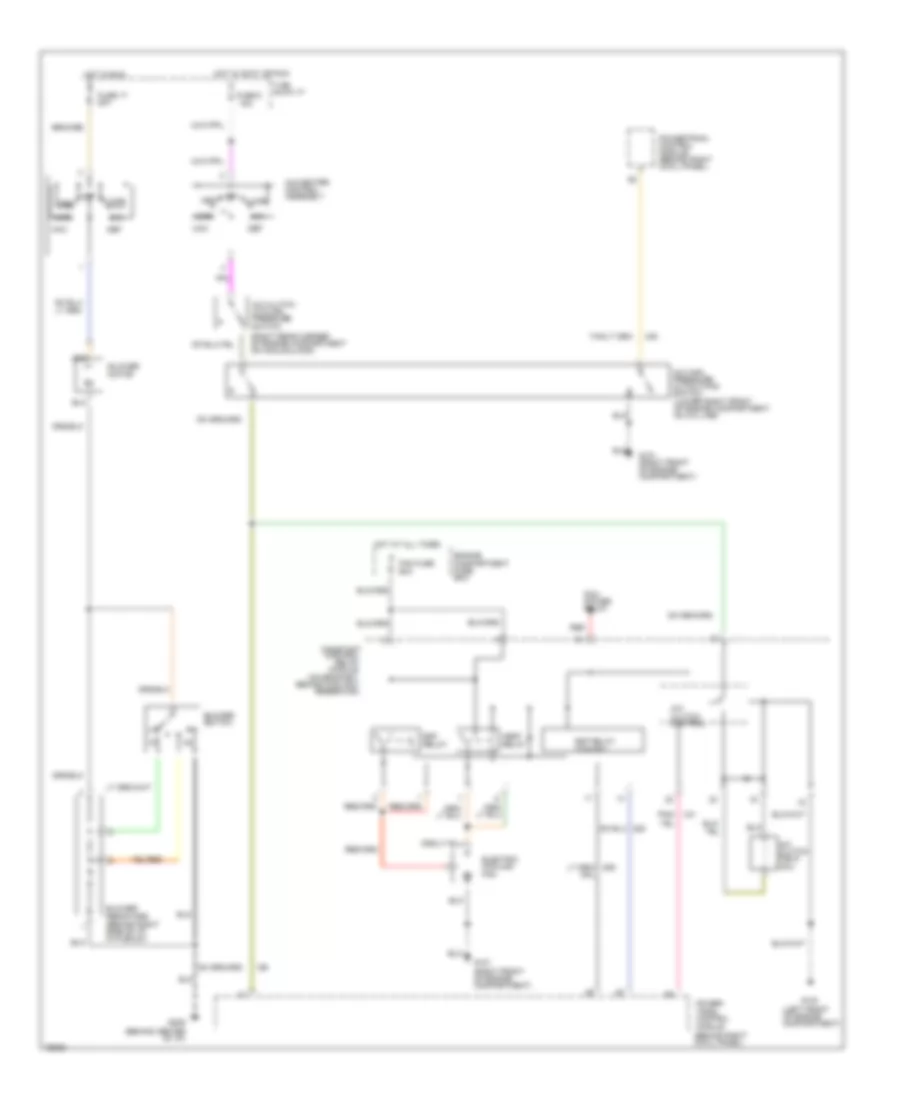
3.8L, A/C Wiring Diagram for Ford Mustang 1996
 https://portal-diagnostov.com/license.html
Automotive Electricians Portal FZCO
Automotive Electricians Portal FZCO
https://portal-diagnostov.com/license.html
https://portal-diagnostov.com/license.html
Automotive Electricians Portal FZCO
Automotive Electricians Portal FZCO
List of elements for 3.8L, A/C Wiring Diagram for Ford Mustang 1996:
- (behind center of i/p)
- (behind right cowl panel)
- (left front of engine compartment)
- (on bracket, behind coolant reservoir)
- (right rear corner of engine compartment on accumulaor)
- A/c clutch control
- A/c clutch cycling pressure switch
- A/c clutch field coil
- A/c high pressure cutout/fan switch (lower right front of engine compartment, on a/c line)
- A/c-heater control assembly
- Blower motor
- Blower resistors (behind right side of i/p, in plenum)
- Blower switch
- Constant control
- Def
- Edf relay
- Edf relay control
- Electric cooling fan
- Engine compartment fuse box
- Fan fuse 60a
- Floor
- Fuse 17 30a
- Fuse 6 15a
- G100
- G101 (right front of engine compartment)
- G206
- Hot at all times
- Hot in accy or run
- Hot in run
- I/p fuse panel
- Max
- Mix
- Module
- Norm
- Off
- Pcm power relay
- Pnk/
- Power- train control module
- Relay
- Vent
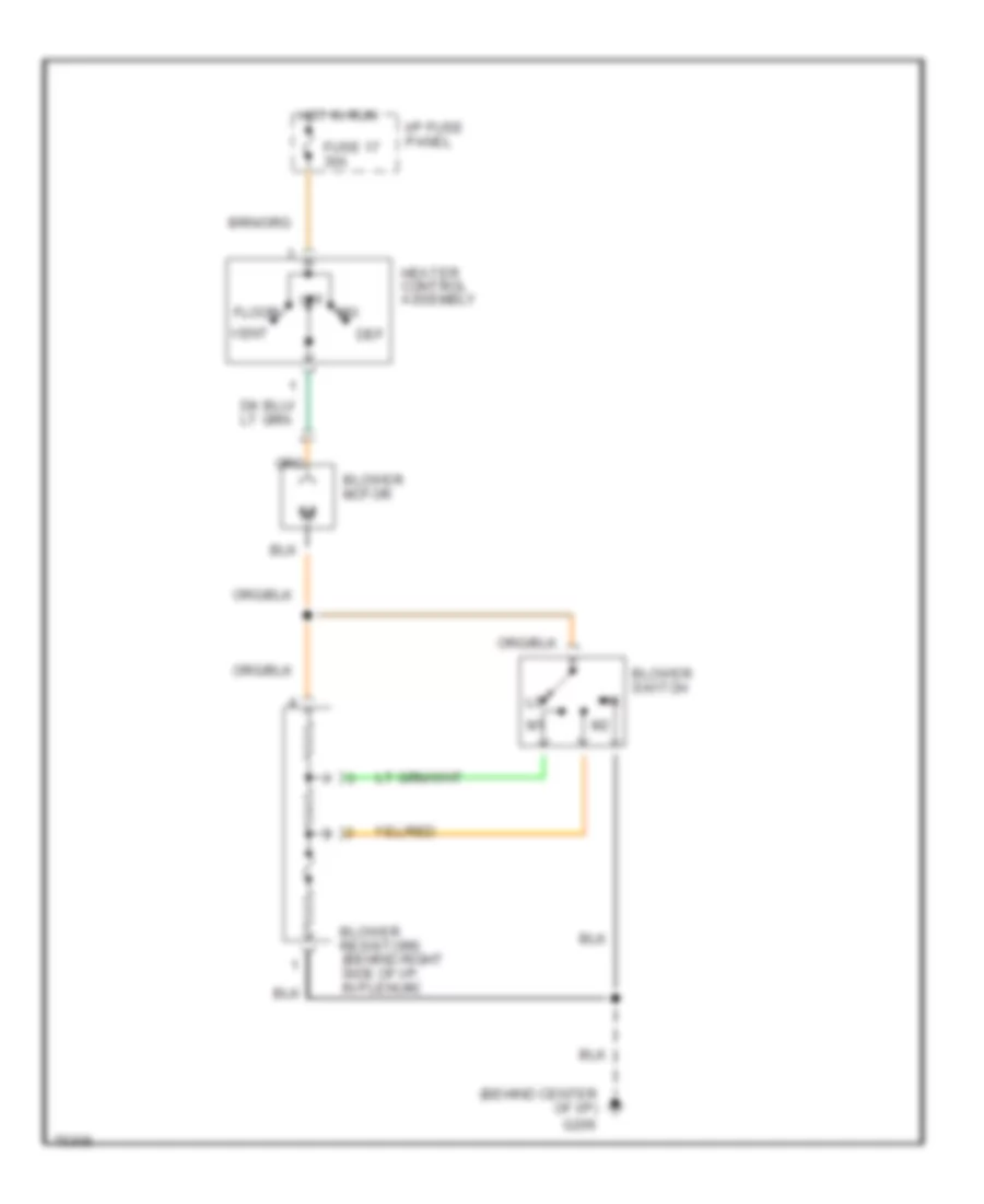
Heater Wiring Diagram for Ford Mustang 1996
List of elements for Heater Wiring Diagram for Ford Mustang 1996:
- (behind center of i/p)
- Blower motor
- Blower resistors (behind right side of i/p, in plenum)
- Blower switch
- Def
- Floor
- Fuse 17 30a
- G206
- Heater control assembly
- Hot in run
- I/p fuse panel
- Mix
- Off
- Vent
4.6L
4.6L, A/C Wiring Diagram for Ford Mustang 1996
List of elements for 4.6L, A/C Wiring Diagram for Ford Mustang 1996:
- (behind center of i/p)
- (behind right cowl panel)
- (left front of engine compartment)
- (on bracket, behind coolant reservoir)
- (right rear corner of engine compartment on accumulaor)
- A/c clutch control
- A/c clutch cycling pressure switch
- A/c clutch field coil
- A/c high pressure cutout/fan switch (lower right front of engine compartment, on a/c line)
- A/c-heater control assembly
- Blower motor
- Blower resistors (behind right side of i/p, in plenum)
- Blower switch
- Constant control
- Def
- Edf relay
- Edf relay control
- Electric cooling fan
- Engine compartment fuse box
- Fan fuse 60a
- Floor
- Fuse 17 30a
- Fuse 6 15a
- Fuse block:i/p
- G100
- G101 (right front of engine compartment)
- G206
- Hedf relay
- Hot at all times
- Hot in accy or run
- Hot in run
- Max
- Mix
- Module
- Norm
- Off
- Pcm power relay
- Pnk/
- Power- train control module
- Powertrain control module (behind right cowl panel)
- Red
- Relay
- Vent
Heater Wiring Diagram for Ford Mustang 1996
List of elements for Heater Wiring Diagram for Ford Mustang 1996:
- (behind center of i/p)
- Blower motor
- Blower resistors (behind right side of i/p, in plenum)
- Blower switch
- Def
- Floor
- Fuse 17 30a
- G206
- Heater control assembly
- Hot in run
- I/p fuse panel
- Mix
- Off
- Vent

 Čeština
 Dansk
Dansk Deutsch
 Ελληνικά
 English
 English
 Español
 Suomi
Suomi Français
 עברית
עברית Hrvatski
 Magyar
 Italiano
 日本語
日本語 한국어
한국어 Nederlands
 Polski
 Português
 Português
 Română
 Русский
 Slovenčina
 Slovenščina
 Svenska
 Türkçe
 中文 (中国)