COOLING FAN
Cooling Fan Wiring Diagram for Ford Econoline E250 2008
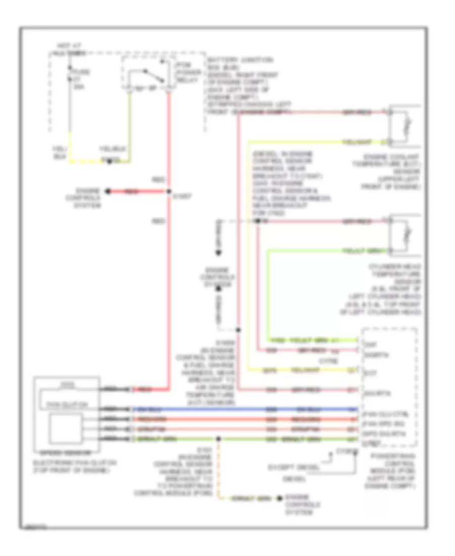
List of elements for Cooling Fan Wiring Diagram for Ford Econoline E250 2008:
- (4.6l & 5.4l: top front of left cylinder head)
- (diesel: in engine control sensor harness, near breakout to c1047) (gas: in engine control sensor & fuel charge harness, near breakout for c192) s136
- Battery junction box (bjb) (diesel: right front of engine compt) (gas: left side of engine compt) (stripped chassis: left front of engine compt)
- C1381e
- C175e
- Cht
- Cylinder head temperature sensor (6.8l: front of left cylinder head)
- Diesel
- Ect
- Electronic fan clutch (top front of engine)
- Engine controls system
- Engine coolant temperature (ect) sensor (upper left front of engine)
- Except diesel
- Fan clu ctrl
- Fan clutch
- Fan spd sig
- Fuse 30a
- Hot at all times
- Nca
- Pcm power relay
- Powertrain control module (pcm) (left rear of engine compt)
- Red
- S101 (in engine control sensor harness, near breakout to to powertrain control module (pcm))
- S1033
- S1057
- S1059 (in engine control sensor & fuel charge harness, near breakout to air charge temperature (act) sensor)
- Sig rtn
- Sigrtn
- Spd sig rtn
- Speed sensor
- Vref
 Čeština
 Dansk
Dansk Deutsch
 Ελληνικά
 English
 English
 Español
 Suomi
Suomi Français
 עברית
עברית Hrvatski
 Magyar
 Italiano
 日本語
日本語 한국어
한국어 Nederlands
 Polski
 Português
 Português
 Română
 Русский
 Slovenčina
 Slovenščina
 Svenska
 Türkçe
 中文 (中国)
 Français