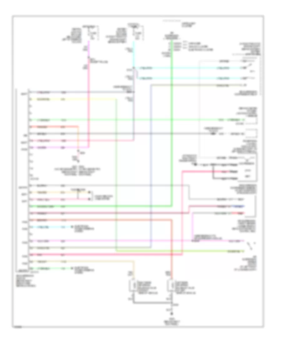
ELECTRONIC SUSPENSION
Electronic Suspension Wiring Diagram for Mercury Grand Marquis GS 2004
List of elements for Electronic Suspension Wiring Diagram for Mercury Grand Marquis GS 2004:
- (at front of right front fender apron) g102
- (behind center of dash) lighting control module
- (in right front of engine compt, behind battery) battery junction box
- (near breakout to air suspension module) s246
- (near breakout to c212) s226
- (near breakout to c214) s206
- (w/o keyless entry) (behind right kick panel)
- Air suspension compressor assembly (at left side front of engine compt)
- Air suspension compressor relay
- Air suspension disable switch (at left front of luggage compt)
- Air suspension height sensor (under rear of vehicle attached to control arm)
- Air suspension indicator
- Air suspension module (behind right side of dash, above glove box)
- Analog cluster
- Battery junction box (bjb) (in right front of engine compt, behind battery)
- C2131a
- C2131b
- C2145c
- C220a
- C2220a
- Central junction box (cjb) (below dash, left of steering column)
- Compressor
- Computer data lines system
- Electronic cluster
- Electronic power steering system
- Fuse 15a
- Fuse 30a
- G200 (behind right kick panel)
- G201 g202 (w/ keyless entry) (behind right kick panel)
- Hot at all times
- Hot in run
- Instrument cluster
- Left rear air spring solenoid valve (at left rear of vehicle)
- Marauder
- Nca
- Pnk
- Powertrain control module (pcm) (in engine compt, on left side of firewall)
- Pwr
- Red
- Right rear air spring solenoid valve (at right rear of vehicle)
- S100
- S112
- S205
- S274 (except police)
- S406
- Scp+
- Scp-
- Sig rtn
- Twisted pair
- Vbatt
- Vent
- Vpwr
- Vss
 Čeština
 Dansk
Dansk Deutsch
 Ελληνικά
 English
 English
 Español
 Suomi
Suomi Français
 עברית
עברית Hrvatski
 Magyar
 Italiano
 日本語
日本語 한국어
한국어 Nederlands
 Polski
 Português
 Português
 Română
 Русский
 Slovenčina
 Slovenščina
 Svenska
 Türkçe
 中文 (中国)
 Français