POWER DISTRIBUTION
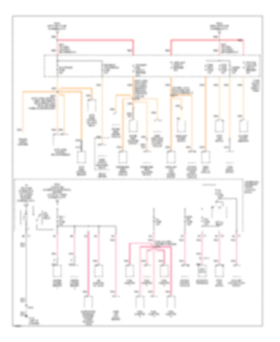
Power Distribution Wiring Diagram (1 of 4) for Oldsmobile Silhouette GLS 2000
 https://portal-diagnostov.com/license.html
Automotive Electricians Portal FZCO
Automotive Electricians Portal FZCO
https://portal-diagnostov.com/license.html
https://portal-diagnostov.com/license.html
Automotive Electricians Portal FZCO
Automotive Electricians Portal FZCO
List of elements for Power Distribution Wiring Diagram (1 of 4) for Oldsmobile Silhouette GLS 2000:
- (body harn, left rear wheelwell) s326
- (diagram 1 of 4)
- (diagram 2 of 4)
- (diagram 3 of 4)
- (i/p harn, 21cm from from radio breakout)
- Air pump fuse 30a
- Air pump relay
- Alt/ sense fuse 10a
- B(+)
- B/u lamp fuse 10a
- Batt main 1 maxi fuse 60a
- Batt main 2 maxi fuse 60a
- Battery
- Body control module
- Cigar lighter
- Cigar/ dlc fuse 15a
- Cluster batt fuse 10a
- Cool fan 1 maxi fuse 30a
- Cool fan 1 relay
- Cool fan 2 maxi fuse 30a
- Cool fan 2 relay
- Cool fan relay
- Ctsy lamp fuse 10a
- Data link connector
- Daytime running lamps control module
- Driver information display
- E12
- Ecm sense fuse 10a
- Electronic brake control module
- Fog lamp relay
- Fog lp fuse 10a
- From radio fuse a
- Front electric accessory plug housing
- Frt pwr sckt fuse 20a
- Fuel pump fuse 15a
- Fuel pump relay
- Fuse block (right side of dash)
- Fusible link a (10ga-rust)
- G201 (right side of dash, left of heater-a/c vent)
- Generator
- Head- lamps maxi fuse 60a
- Headlamp & i/p lamp dimmer switch
- Heater/ a/c control
- Horn fuse 15a
- Horn relay
- Ign main 1 maxi fuse 40a
- Ign main 2 maxi fuse 60a
- Ign main relay (diagram 2 of 4)
- Instrument cluster
- Outside rearview mirror remote control switch
- Park lp fuse 20a
- Powertrain control module
- Pwr lock fuse 20a
- Pwr mirror fuse 10a
- Radio
- Radio fuse 10a
- Rap relay fuse 10a
- Rear electric accessory plug housing
- Rear side door actuator control module
- Red
- Relay center
- Remote control door lock receiver
- Rr pwr sckt fuse 20a
- S202
- S230
- S238 (i/p harn, 80cm from the cigar lighter connector)
- S276 (i/p harn, 8cm from bcm breakout)
- Security indicator lamp
- Starter motor
- Theft deterrent relay
- Theft deterrent shock sensor
- To cool fan 1 fuse (diagram 1 of 4)
- To ignition switch pin d2
- To ignition switch pin d5
- To rap relay (diagram 4 of 4)
- To s274
- To s278
- Transaxle range switch
- Underhood accessory wiring junction block
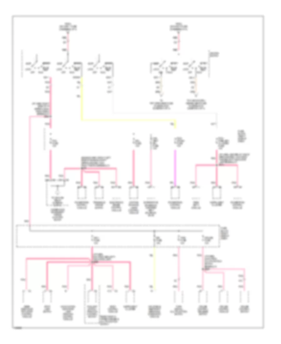
Power Distribution Wiring Diagram (2 of 4) for Oldsmobile Silhouette GLS 2000
List of elements for Power Distribution Wiring Diagram (2 of 4) for Oldsmobile Silhouette GLS 2000:
- (body harn, 34cm from nflatable restraint sensing & diagnostic module) s302
- (diagram 1 of 4)
- (fuel inj harn, center of engine) s109
- (i/p harn, 13 cm from headlamp switch breakout) s215
- A/c clu fuse 10a
- A/c clu relay
- A12
- Air injection bl valve
- Auto level control air compressor
- Auto level control inflator relay
- Auto level control sensor
- Automatic transaxle
- Auxiliary coolant pump switch
- Blower motor resistor
- C111
- Ctrl sols
- Daytime running lamps control module
- Driver seat adjuster switch
- Driver seat heater module
- Elc/trailer fuse 25a
- Elek ign fuse 15a
- Evaporative emissions canister purge solenoid valve
- From batt main 2 fuse
- From headlamps fuse
- From horn fuse (underhood electrical center) (hot at all times) (diagram 1 of 4)
- Frt hvac hi blowr circuit breaker 30a
- Fuel injector
- Fuse block (right side of dash)
- G110 (left of starter)
- Hazard fuse 15a
- Headlamp & i/p lamp dimmer switch
- Headlamp circuit breaker 20a
- Headlamp dimmer switch
- Heated oxygen sensor
- Ign 1- u/h fuse 15a
- Ign main relay
- Ignition control module
- Inj fuse 10a
- Mass air flow sensor
- Nca
- Pass key iii fuse 10a
- Pass key iii module
- Passenger seat adjuster switch
- Passenger seat heater module
- Pnk
- Pwr seat/ psd circuit breaker 30a
- Rear side door actuator control module
- Rear window defogger relay
- Red
- Relay center
- Rr defog/ htd mirrors fuse 30a
- S106
- S274 (i/p harn, 4cm from bcm breakout)
- S278 (i/p harn, 12cm from bcm breakout)
- S445 (auto level control harn, left rear of body approx 16cm from left rear wheelhouse grommet)
- Stop lamp fuse 15a
- Stop lamp switch
- Stop- lamp switch
- Tcc fuse 10a
- To pcm fuse (fuse block) (hot in run, bulb test or start) (diagram 3 of 4)
- Trailer wiring harness
- Turn signal switch
- Underhood accessory wiring junction block
Power Distribution Wiring Diagram (3 of 4) for Oldsmobile Silhouette GLS 2000
List of elements for Power Distribution Wiring Diagram (3 of 4) for Oldsmobile Silhouette GLS 2000:
- (engine harn, front left side of engine compt approxiamately 8cm from the pcm breakout) s108
- (i/p harn, 24cm from multifunction switch breakout) s266
- (i/p harn, 8cm from security indicator lamp) s209
- (i/p harn, center of the i/p aproxiamately 4cm from the security indicator lamp breakout) s210
- (i/p harn, right side of i/p approx 25cm from radio breakout) s228
- A11
- A13
- Acc
- Acc 1
- Body control module
- Bulb test
- C10
- C13
- Can vent sol fuse 10a
- Crank
- Cruise control module
- Cruise control release switch
- Cruise control switch
- Cruise fuse 10a
- D11
- Daytime running lamps control module
- Drl fuse 10a
- Electronic brake control module
- Evaporative emissions canister vent solenoid valve
- Foglamp switch/ traction control switch
- From ign main 1 fuse (diagram 1 of 4)
- From ign main 2 fuse (diagram 1 of 4)
- Fuse block (right side of dash)
- Ign 0
- Ign 1
- Ign 1 fuse 10a
- Ign 3
- Ignition switch
- Inflatable restraint sensing & diagnostic module
- Instrument cluster
- Lock
- Malfunction indicator lamp traction control module
- Off
- Pass key iii module
- Pcm fuse 10a
- Pcm/ crank fuse 10a
- Pcm/ pass key/ cluster fuse 10a
- Pnk
- Powertrain control module
- Rear side door actuator control module
- Rear window wiper/washer & multifunction switch
- Red
- Run
- Sir fuse 15a
- Start
- Stop lamp switch
- T/sig fuse 10a
- To frt wpr/wshr fuse (fuse block) (diagram 4 of 4)
- To hvac/dic/drl/ heated seat fuse (fuse block) (diagram 4 of 4)
- To ign main relay (diagram 2 of 4)
- Transaxle range switch
- Turn signal/ multifunction switch
- Underhood accessory wiring junction block
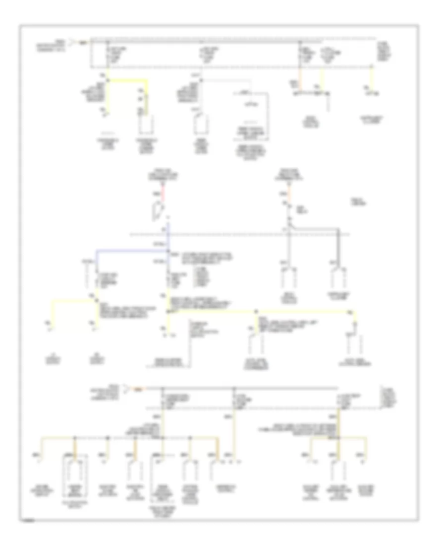
Power Distribution Wiring Diagram (4 of 4) for Oldsmobile Silhouette GLS 2000
List of elements for Power Distribution Wiring Diagram (4 of 4) for Oldsmobile Silhouette GLS 2000:
- (body harn, in front of left rear wheelhouse approx 48cm from left rear side door jamb switch) s345
- (body harn, under right front door sill, approxiamately 17cm from harness breakout) s317
- (diagram 1 of 4)
- (i/p harn, 16cm from relay center breakout) s264
- (i/p harn, right side of the i/p at the electric air inlet actuator breakout)
- Auto level control air compressor
- Auto level control sensor
- Auxiliary blower motor
- Auxiliary heater- a/c control
- Auxiliary temperature valve actuator
- Bcm prgrm fuse 10a
- Body control module
- Daytime running lamps control module
- Driver information display
- Electric air inlet actuator
- Electric slave actuator
- From ign main 2 maxi fuse (diagram 1 of 4)
- From ignition switch
- From ignition switch (hot in run) (diagram 3 of 4)
- From rap relay fuse (diagram 1 of 4)
- Frt wpr/ wshr fuse 25a
- Fuse block (right side of dash)
- Heated seat switch
- Heater-a/c control
- Hvac blower fuse 25a
- Hvac/dic/drl/ heated seat fuse 10a
- Hvac/temp cont fuse 25a
- Instrument cluster
- Interior lamp & multifunction switch
- Lf window switch
- Mall/ cluster fuse 10a
- Multifuntion switch
- Nca
- Pwr otr vent fuse 10a
- Pwr wdo circuit breaker 30a
- Rap relay
- Rear quarter window switch
- Rear window defogger relay
- Rear window wiper motor
- Rear window wiper/ washer switch
- Rear window wiper/washer & multifunction switch
- Red
- Relay center
- Relay center (right side of dash)
- Rf window switch
- Rr wpr/ wshr fuse 20a
- S245 (i/p harn, approx 5cm from radio breakout)
- S249 (i/p harn, approx 14cm bulkhead grommet)
- S263
- S307 (boyd harn, right front door approxiamately 4cm from the door harn breakout)
- S440 (auto level control harn, left rear of the body behind left wheelhouse)
- Windshield wiper motor
- Windshield wiper/ washer switch

 Čeština
 Dansk
Dansk Deutsch
 Ελληνικά
 English
 English
 Español
 Suomi
Suomi Français
 עברית
עברית Hrvatski
 Magyar
 Italiano
 日本語
日本語 한국어
한국어 Nederlands
 Polski
 Português
 Português
 Română
 Русский
 Slovenčina
 Slovenščina
 Svenska
 Türkçe
 中文 (中国)