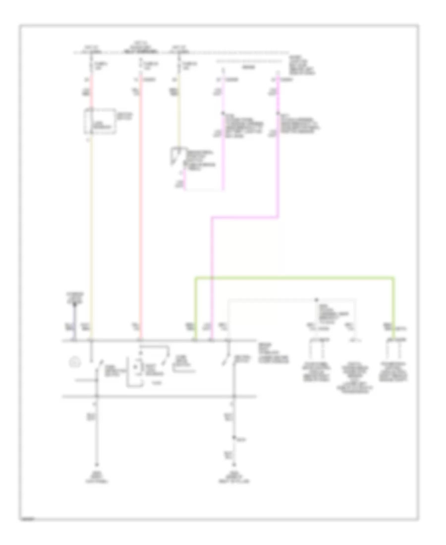
SHIFT INTERLOCK
Shift Interlock Wiring Diagram for Ford Explorer Sport Trac 2007
List of elements for Shift Interlock Wiring Diagram for Ford Explorer Sport Trac 2007:
- (under center floor console)
- All times
- Brake pedal position switch (above brake pedal)
- Brake shift interlock
- C175b
- C2280c
- C2280e
- C281b
- Digital transmission range (dtr) sensor (4.0l) (lower left side of automatic transmission)
- Four-wheel drive control module (behind right side of dash)
- Fuse 20 10a
- Fuse 22 15a
- Fuse 8 15a
- G200 (right kick panel)
- G302 (base of right "b" pillar)
- Hot at
- Hot w/
- Ignition switch
- Interior lights system
- Lock solenoid
- Neutral switch
- Over drive switch
- Park detection switch
- Powertrain control module (pcm) (right rear of engine compt)
- Run/start relay energized
- S128 (in dash panel to engine harness, near breakout to battery junction box (bjb))
- S200 (in main harness, near breakout to c215)
- S217 (in main harness, near breakout to accelerator pedal position sensor)
- S219
- Sense
- Shift lock solenoid
- Smart junction box (sjb) (behind left side of dash)
 Čeština
 Dansk
Dansk Deutsch
 Ελληνικά
 English
 English
 Español
 Suomi
Suomi Français
 עברית
עברית Hrvatski
 Magyar
 Italiano
 日本語
日本語 한국어
한국어 Nederlands
 Polski
 Português
 Português
 Română
 Русский
 Slovenčina
 Slovenščina
 Svenska
 Türkçe
 中文 (中国)
 Français