SHIFT INTERLOCK
Shift Interlock Wiring Diagram for Mercury Milan Premier 2009
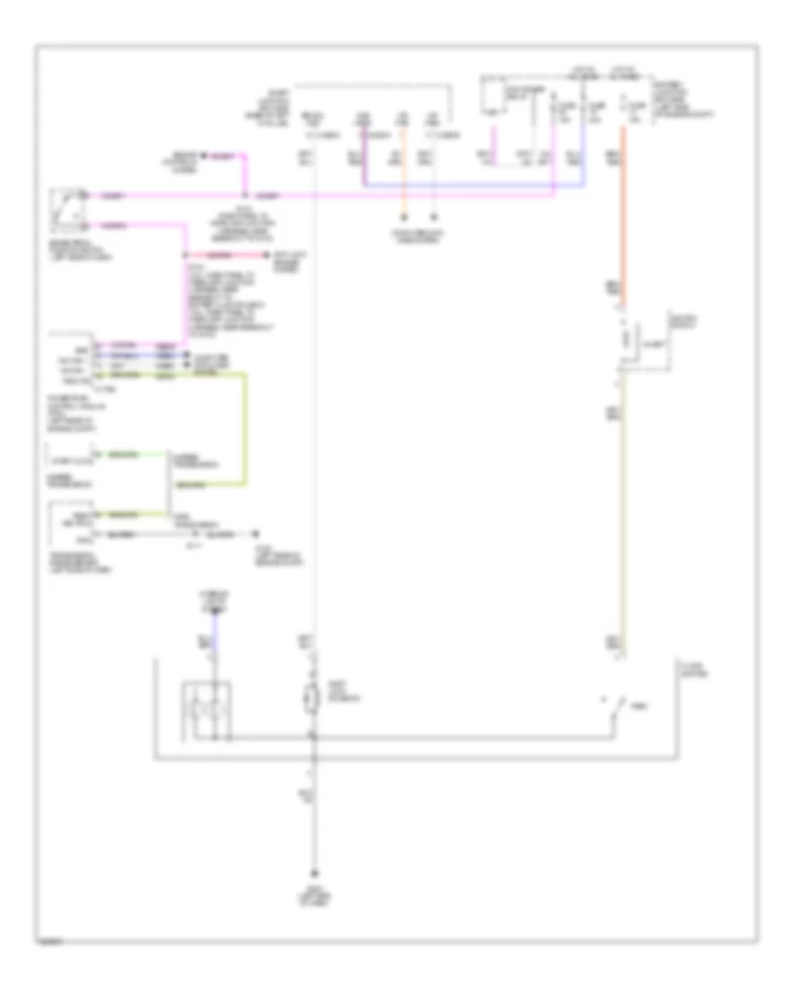
List of elements for Shift Interlock Wiring Diagram for Mercury Milan Premier 2009:
- 6 speed transmission
- Anti-lock brakes system
- Battery junction box (bjb) (left side of engine compt)
- Bps
- Brake pedal position switch (left side of dash)
- Bsi sol cmd
- C175b
- C2280a
- C2280c
- C2280d
- Ces09
- Cet40
- Computer data lines system
- Engine controls system
- Floor
- Fnr5 transmission
- Fuse 15a
- Fuse 40a
- G102 (left rear of engine compt)
- G202 (left side of dash)
- Gnd
- Hot at all times
- Hs can +
- Hs can -
- Ignition switch
- Inhibit
- Interior lights system
- Ms can+
- Ms can-
- Park
- Park/ neutral
- Pcm power relay
- Powertrain control module (pcm) (left rear of engine compt)
- S111
- S133 (2.3l: dash panel to headlamp junction harness, near breakout to battery junction box) (3.0l: dash panel to headlamp junction harness, near breakout to g103)
- S144 (dash panel to headlamp junction harness, near breakout to g103)
- Shift lock solenoid
- Shifter
- Sjb logic
- Smart junction box (sjb) (base of left "a" pillar)
- Start lock
- Transmission range sensor (left side of dash)
- Trsw pn
- Vdb04
- Vdb05
 Čeština
 Dansk
Dansk Deutsch
 Ελληνικά
 English
 English
 Español
 Suomi
Suomi Français
 עברית
עברית Hrvatski
 Magyar
 Italiano
 日本語
日本語 한국어
한국어 Nederlands
 Polski
 Português
 Português
 Română
 Русский
 Slovenčina
 Slovenščina
 Svenska
 Türkçe
 中文 (中国)
 Français