SUPPLEMENTAL RESTRAINTS
Supplemental Restraints Wiring Diagram (1 of 2) for Ford Explorer 2005
 https://portal-diagnostov.com/license.html
Automotive Electricians Portal FZCO
Automotive Electricians Portal FZCO
https://portal-diagnostov.com/license.html
https://portal-diagnostov.com/license.html
Automotive Electricians Portal FZCO
Automotive Electricians Portal FZCO
List of elements for Supplemental Restraints Wiring Diagram (1 of 2) for Ford Explorer 2005:
- (in main harness, near breakout to audio unit)
- Air bag ind
- Air bag ind ctrl
- Air bag monitor
- Battery
- Battery junction box (bjb) (left side of engine compartment, at fender apron)
- C175b
- C220a
- C220b
- C228b
- C270e
- C310a
- C310b
- Central junction box (cjb) (behind left side of dash)
- Computer data lines system
- Data link connector (dlc) (behind left side of dash)
- Driver 1 side impact sensor (at base of left "b" pillar)
- Driver safety belt buckle pretensioner (under driver seat)
- Driver safety belt buckle switch (under driver seat)
- Dvr air bag stage 2 +
- Dvr air bag stage 2 -
- Electronic automatic temperature control (eatc) module (behind center of dash)
- Fuse 10a
- Fuse 15a
- G205 (under center console)
- G301 (under center console)
- Hot at all times
- Hot in run or start
- Instrument cluster
- Iso
- Logic ground
- Micro- processor
- Nca
- Note: 1: unbuckled 2: buckled
- Pass air bag stage 1 +
- Pass air bag stage 1 -
- Pass air bag stage 2 +
- Pass air bag stage 2 -
- Passenger 1 side impact sensor (at base of right "b" pillar)
- Passenger safety belt buckle pretensioner (under passenger seat)
- Passenger safety belt buckle switch (under passenger seat)
- Pin shorting bars engaged when module connector is disconnected from harness (shorting bars are connected between pins: 1-2, 3-4, 5-6 & 13-14 c310a 3-4 & 5-6 c310b
- Powertrain control module (pcm) (at right side engine bulkhead)
- Red
- Ref/gnd
- Restraints control module (below center console)
- S149
- S228
- S232 (in main harness, near breakout to central junction box)
- S333 (in window regulator jumper assembly, near breakout to restraints control module)
- See note
- Shorting bar
- Signal
- Signal +
- Signal -
- Stage 1 +
- Stage 1 -
- Tone
- Tone driver
- Vbatt
- Vpwr
- W/ dual zone eatc
- W/ right safety canopy
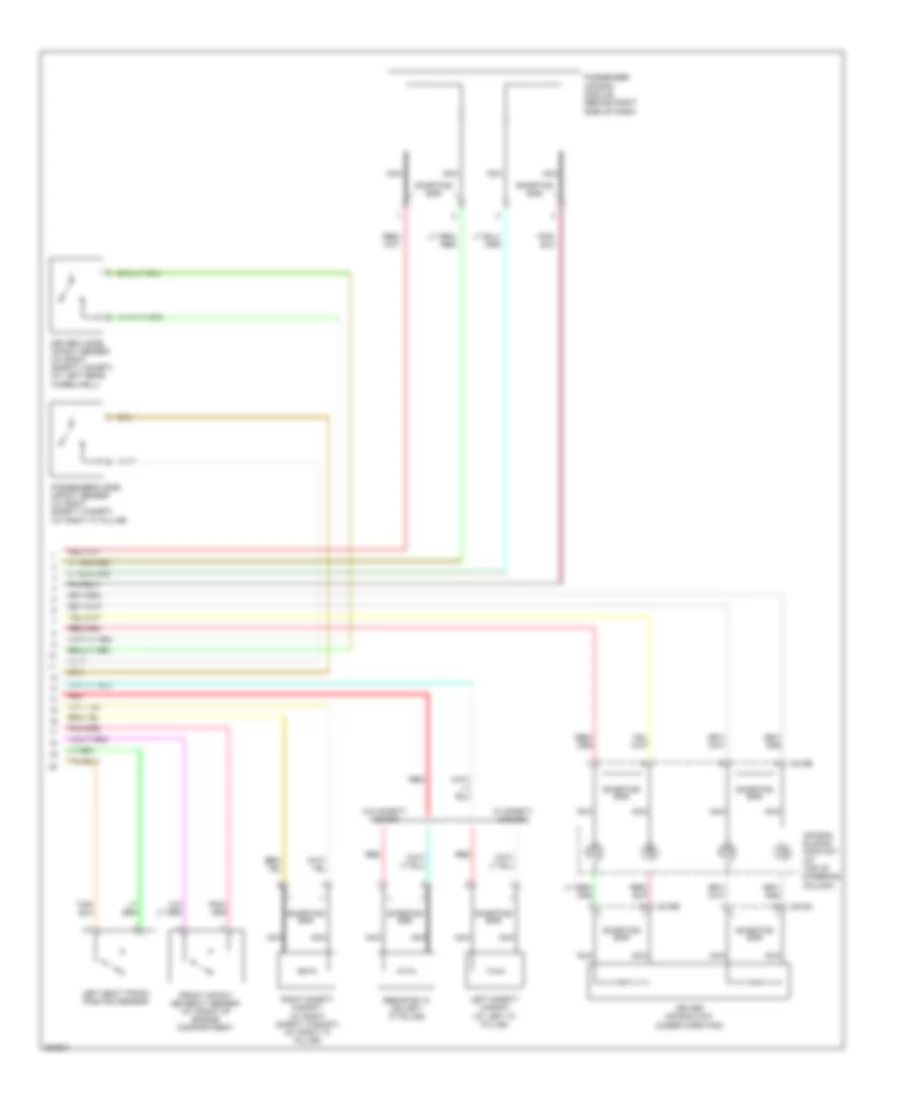
Supplemental Restraints Wiring Diagram (2 of 2) for Ford Explorer 2005
List of elements for Supplemental Restraints Wiring Diagram (2 of 2) for Ford Explorer 2005:
- Air bag sliding contact (at top of steering column)
- C216a
- C216b
- C218b
- Driver 2 side impact sensor (w/ right safety canopy) (at left rear wheelwell)
- Driver air bag unit (under horn pad)
- Front impact severity sensor (at front of engine compartment)
- Left safety canopy (at left "c" pillar)
- Left seat track position sensor
- Nca
- Passenger 2 side impact sensor (w/ right safety canopy) (at right "c" pillar)
- Passenger air bag module (behind right side of dash)
- Red
- Resistor "a" (on left "c" pillar)
- Right safety canopy (w/ right safety canopy) (at right "c" pillar)
- Shorting bar
- W/ safety canopy
- W/o safety canopy

 Čeština
 Dansk
Dansk Deutsch
 Ελληνικά
 English
 English
 Español
 Suomi
Suomi Français
 עברית
עברית Hrvatski
 Magyar
 Italiano
 日本語
日本語 한국어
한국어 Nederlands
 Polski
 Português
 Português
 Română
 Русский
 Slovenčina
 Slovenščina
 Svenska
 Türkçe
 中文 (中国)