SUPPLEMENTAL RESTRAINTS
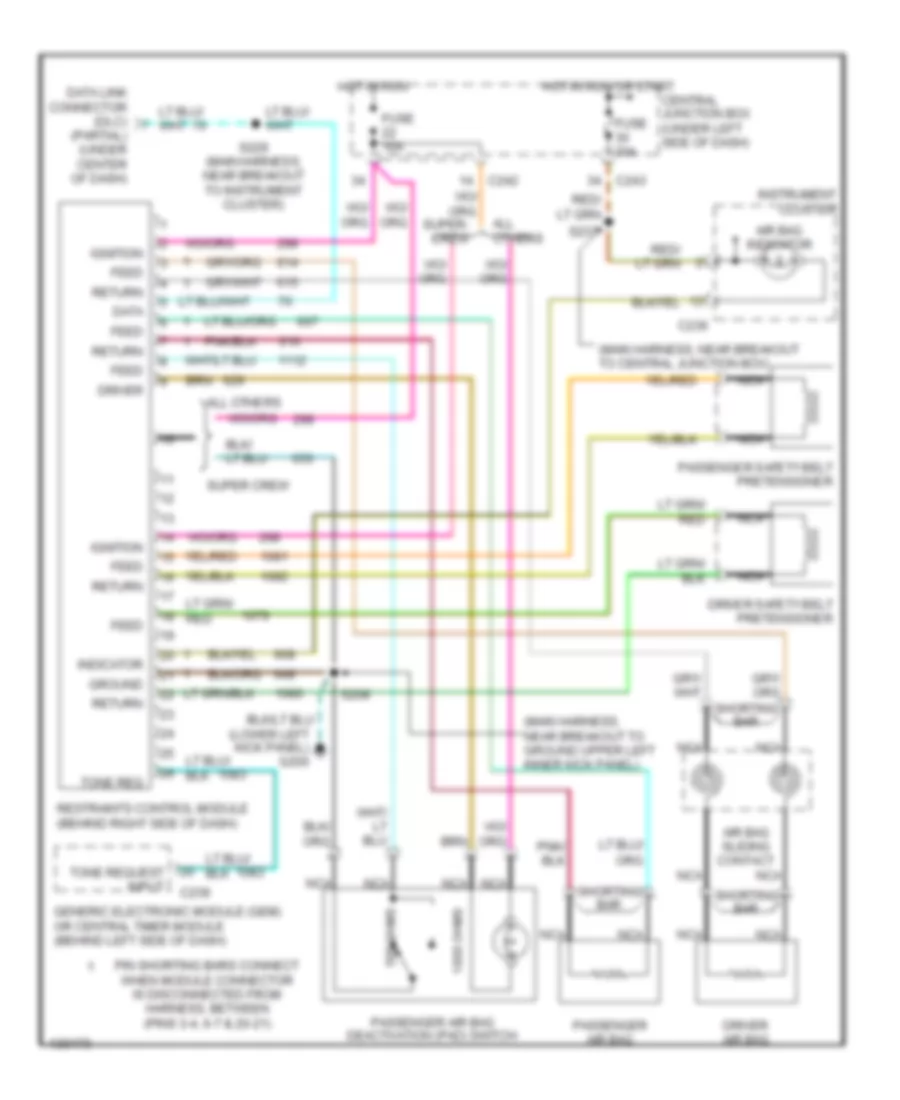
Supplemental Restraint Wiring Diagram for Ford Pickup F150 2001
List of elements for Supplemental Restraint Wiring Diagram for Ford Pickup F150 2001:
- (lower left kick panel) g200
- (main harness, near breakout to central junction box)
- (main harness, near breakout to ground upper left inner kick panel)
- (partial) (under center of dash)
- 1000 ohms
- 500 ohms
- Air bag indicator
- Air bag sliding contact
- All others
- C236
- C239
- C242
- C243
- Central junction box (under left side of dash)
- Data
- Data link connector (dlc)
- Driver
- Driver air bag
- Driver safety belt pretensioner
- Feed
- Fuse 10a
- Fuse 30a
- Generic electronic module (gem) or central timer module (behind left side of dash)
- Ground
- Hot in run
- Hot in run or start
- Ignition
- Indicator
- Instrument cluster
- Nca
- Passenger air bag
- Passenger air bag deactivation (pad) switch
- Passenger safety belt pretensioner
- Pin shorting bars connect when module connector is disconnected from harness, between (pins 3-4, 6-7 & 20-21)
- Restraints control module (behind right side of dash)
- Return
- S208
- S229 (main harness, near breakout to instrument cluster)
- S237
- Shorting bar
- Super crew
- Tone req
- Tone request input
 Čeština
 Dansk
Dansk Deutsch
 Ελληνικά
 English
 English
 Español
 Suomi
Suomi Français
 עברית
עברית Hrvatski
 Magyar
 Italiano
 日本語
日本語 한국어
한국어 Nederlands
 Polski
 Português
 Português
 Română
 Русский
 Slovenčina
 Slovenščina
 Svenska
 Türkçe
 中文 (中国)
 Français