ENGINE PERFORMANCE
5.4L
5.4L, Electronic Catalytic Converter Wiring Diagram for BMW 750iL 1998
 https://portal-diagnostov.com/license.html
Automotive Electricians Portal FZCO
Automotive Electricians Portal FZCO
https://portal-diagnostov.com/license.html
https://portal-diagnostov.com/license.html
Automotive Electricians Portal FZCO
Automotive Electricians Portal FZCO
List of elements for 5.4L, Electronic Catalytic Converter Wiring Diagram for BMW 750iL 1998:
- Auxiliary battery
- Battery
- Battery temperature sensor (right rear of luggage compt)
- Computer data lines system
- Electrical catalytic converter control unit (under right front seat carpet)
- Electrical isolating switch control unit (right rear of luggage compt)
- Engine control module relay 2 (right rear side of engine compt, in e-box)
- Fuse 17 10a
- Fuse 21 5a
- Fuse box
- Hot in run or start
- Integrated instrument cluster control module
- Left electric catalytic converter
- Red
- Right electric catalytic converter
- X10012
- X10016
- X10113
- X13075
- X1779
- X63082
- X63083
- X63084
- X63085
- X63087
- X63089
- X63090
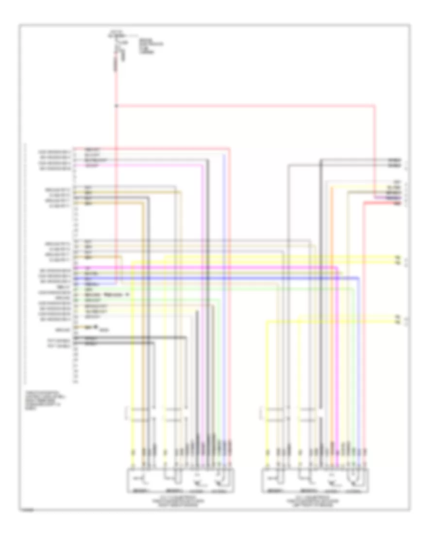
5.4L, Electronic Throttle Control Wiring Diagram (1 of 2) for BMW 750iL 1998
List of elements for 5.4L, Electronic Throttle Control Wiring Diagram (1 of 2) for BMW 750iL 1998:
- 5v sig pot 1
- 5v sig pot 2
- Cos winding sig a
- Cos winding sig b
- Cyl 1-6 electronic throttle position actuator (left front of engine)
- Cyl 7-12 electronic throttle position actuator (right side of engine)
- Engine electronics fuse carrier
- Fuse 30a
- Ground
- Ground pot 1
- Ground pot 2
- Hot at all times
- Motor 1
- Motor 2
- Pot 1 shield
- Pot 2 shield
- Red
- Sensor 1
- Sensor 2
- Shield
- Sin winding sig a
- Sin winding sig b
- Term 87
- Throttle position control module (eml) (right rear side of engine compt, in e-box)
- X6452
- X8680
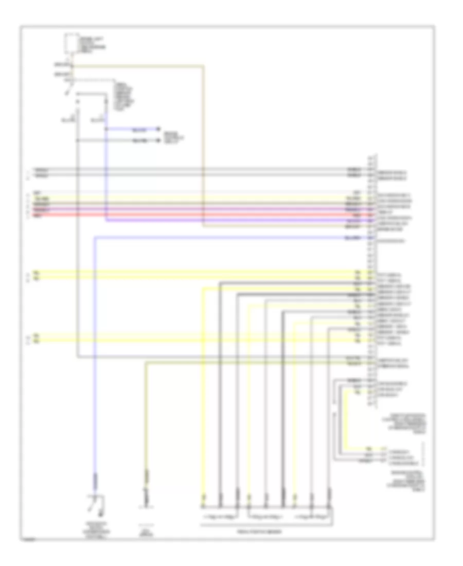
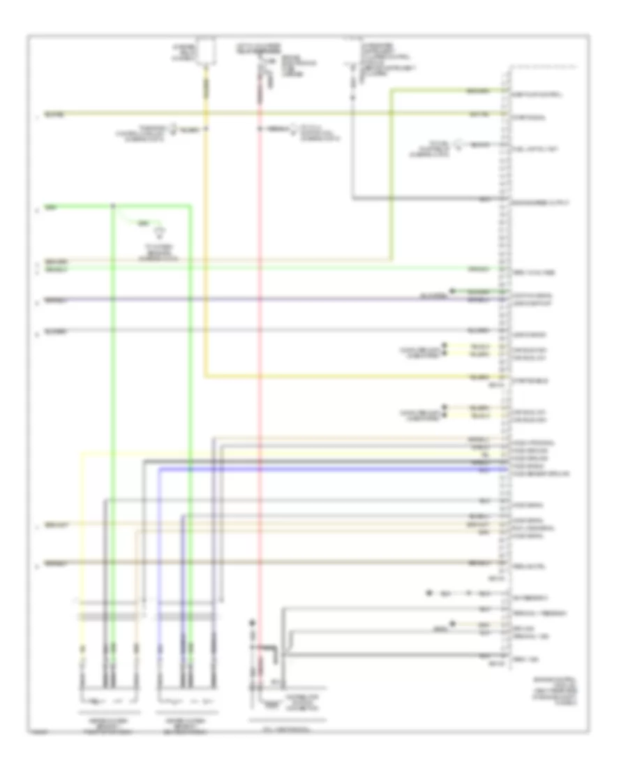
5.4L, Electronic Throttle Control Wiring Diagram (2 of 2) for BMW 750iL 1998
List of elements for 5.4L, Electronic Throttle Control Wiring Diagram (2 of 2) for BMW 750iL 1998:
- (right rear side of engine compt, in e-box)
- Brake light switch (above brake pedal)
- Brake sw sig
- Can bus hi
- Can bus low
- Can bus shield
- Coil spring
- Cos winding sig a
- Cos winding sig b
- Engine control module ii
- Engine controls circuit
- Inertia fuel sw
- Kick down sw
- Kick-down switch (driver's side footwell)
- Nca
- Pedal position sensor
- Pedal position sensor (behind left side of dash top)
- Pot 1 signal
- Pot 2 signal
- Red
- Sens 1 sig out
- Sens 3 sig in
- Sensor 1 shield
- Sensor 1 sig in
- Sensor 2 shield
- Sensor 2 sig osc
- Sensor 2 sig out
- Sensor 3 sig out
- Sensor shield
- Sensor shield 3
- Shield
- Sin winding sig a
- Sin winding sig b
- Steering signal
- Term 87
- Throttle position control module (eml) (right rear side of engine compt, in e-box)
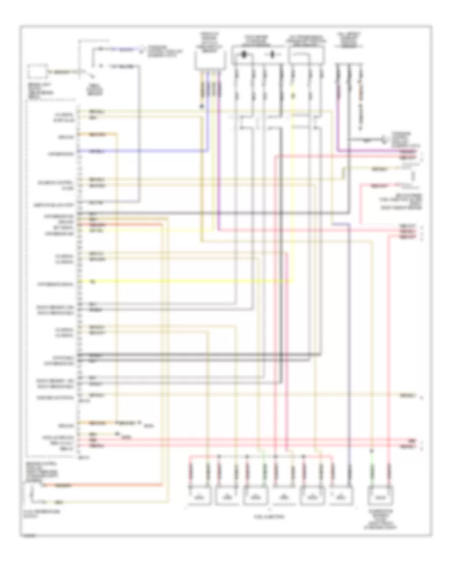
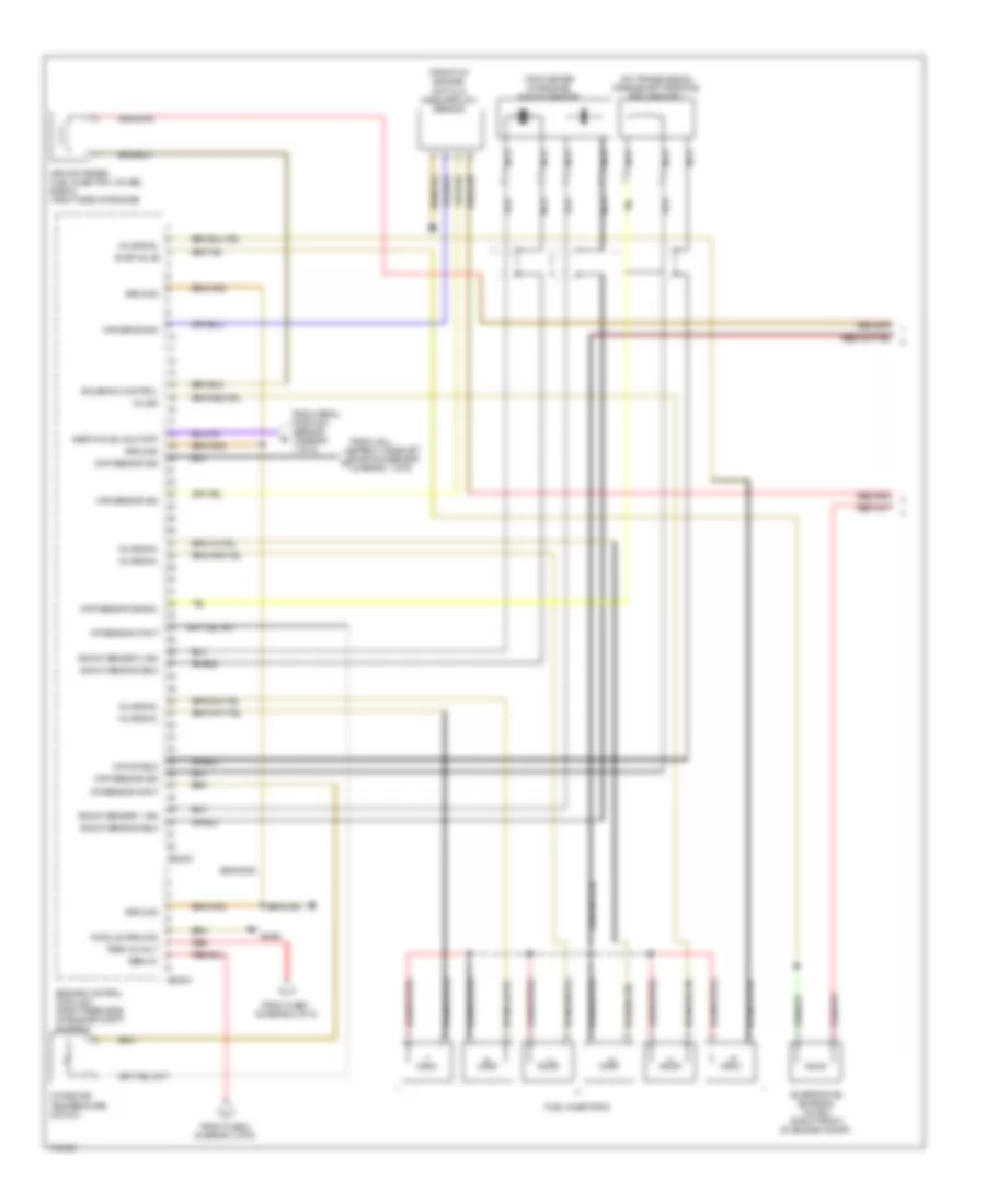
5.4L, Engine Controls Wiring Diagram (1 of 5) for BMW 750iL 1998
List of elements for 5.4L, Engine Controls Wiring Diagram (1 of 5) for BMW 750iL 1998:
- (front of engine)
- (on transmission) crankshaft position/ rpm sensor 1
- (top center of engine) knock sensor
- Air-contained fuel injection valves, bank 1 (right side of engine)
- Brake light switch (above brake pedal)
- Ckp sensor sig
- Ckp sensor signal
- Ckp shield
- Cmp sensor sig
- Dual temperature switch
- Ect signal
- Engine control module i (right rear side of engine compt, in e-box)
- Evap valve
- Evaporative emission valve 1 (right front of engine compt)
- Fuel injectors
- Ground
- Hall effect camshaft position sensor
- Hot film mass airflow sensor
- Inertia fuel shutoff
- Inj sig
- Inj signal
- Knock sens shield
- Knock sensor 1 sig
- Knock sensor 2 sig
- Maf sens gnd
- Maf sensor sig
- Module ground
- Nca
- Pedal position sensor
- Red
- Shield
- Solenoid control
- Term 30 volt
- Term 87
- To engine control module ii (diagram 4 of 5)
- X60101
- X60103
- X6452
- X6454
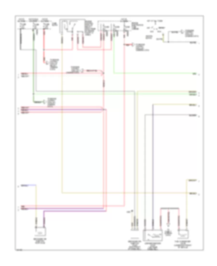
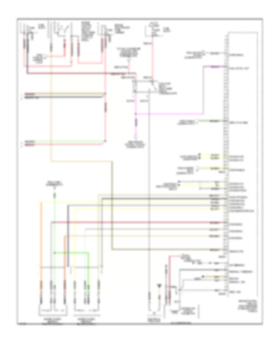
5.4L, Engine Controls Wiring Diagram (2 of 5) for BMW 750iL 1998
List of elements for 5.4L, Engine Controls Wiring Diagram (2 of 5) for BMW 750iL 1998:
- Acc
- Engine control module relay 1 (right rear of engine compt, in e-box)
- Engine electronics fuse carrier
- Fuel changeover valve (under right front of vehicle)
- Fuse 30a
- Fuse 50a
- Fuse 5a
- Fuse 80a
- Fuse block
- Hot at all times
- Hot in run or start
- Ignition switch
- Leakage diagnosis pump (left rear wheelwell)
- Off
- Red
- Run
- Secondary air injection pump (right front of wheelwell)
- Secondary air injection pump valve
- Start
- To engine control module ii (diagram 4 of 5)
- To engine control module ii (diagram 5 of 5)
- To engine control module relay ii (diagram 5 of 5)
- To fuse 17 (diagram 5 of 5)
- X10016
- X493
- X8680
5.4L, Engine Controls Wiring Diagram (3 of 5) for BMW 750iL 1998
List of elements for 5.4L, Engine Controls Wiring Diagram (3 of 5) for BMW 750iL 1998:
- A/c system
- Can bus high
- Can bus low
- Comp on signal
- Computer data lines system
- Cyl 1 ignition coil
- Distributor ignition connection
- Engine control module i (right rear side of engine compt, in e-box)
- Engine electronics fuse carrier
- Engine speed output
- Fuel unit rly act
- Fuse 30a
- Ground
- Heated oxygen sensor 1 behind cat conv
- Heated oxygen sensor 1 front of cat conv
- Ho2s ground
- Ho2s htr signal
- Ho2s sensor ground
- Ho2s shield
- Ho2s signal
- Hot w/ unloader relay energized
- Ign feedback
- Integrated instrument cluster control module (behind instrument x10114 cluster)
- Leak diag pump
- Leak diag sig
- Nca
- Run loss signal
- Sair pump control
- Shield
- Start enable
- Start signal
- Starter relay (in e-box)
- Term 1 sig
- Term 15 voltage
- Term 85 ctrl
- Terminal 1 feedback
- Terminal 1 sig
- To cyl 2 ignition coil (diagram 5 of 5)
- To engine control module ii (diagram 5 of 5)
- To fuel pump relay (diagram 5 of 5)
- To oxygen sensors (diagram 5 of 5)
- X60102
- X60104
- X60105
- X6452
- X8680
5.4L, Engine Controls Wiring Diagram (4 of 5) for BMW 750iL 1998
List of elements for 5.4L, Engine Controls Wiring Diagram (4 of 5) for BMW 750iL 1998:
- (diagram 1 of 5)
- (front of engine)
- (on transmission) crankshaft position/ rpm sensor 1
- (top center of engine) knock sensor
- Air-contained fuel injection valves, bank 2 (right side of engine)
- Ckp sensor sig
- Ckp sensor signal
- Ckp shield
- Cmp sensor sig
- Engine control module ii (right rear side of engine compt, in e-box)
- Evap valve
- Evaporative emission valve 2 (right front of engine compt)
- From fuse 1 (diagram 2 of 5)
- From fuse 2 (diagram 2 of 5)
- From hall effect camshaft position sensor d
- From pedal position sensor (diagram 1 of 5)
- Fuel injectors
- Ground
- Hot film mass airflow sensor
- Iat sensor input
- Inertia fuel shutoff
- Inj sig
- Inj signal
- Intake air temperature switch
- Knock sens shield
- Knock sensor 1 sig
- Knock sensor 2 sig
- Maf sens gnd
- Maf sensor sig
- Module ground
- Nca
- Red
- Shield
- Solenoid control
- Term 30 volt
- Term 87
- X60201
- X60203
- X6453
5.4L, Engine Controls Wiring Diagram (5 of 5) for BMW 750iL 1998
List of elements for 5.4L, Engine Controls Wiring Diagram (5 of 5) for BMW 750iL 1998:
- Can bus high
- Can bus low
- Can bus shield
- Computer data lines system
- Cyl 2 ignition coil
- Distributor ignition connection
- Electrical fuel pump
- Electronic throttle control circuit
- Engine control module ii (right rear side of engine compt, in e-box)
- Engine control module relay 2 (right rear of engine compt, in e-box)
- Engine electronics fuse carrier
- From engine control module i (diagram 3 of 5)
- From fuse 109 h (diagram 2 of 5)
- From fuse 24 l (diagram 2 of 5)
- From fuse 3 (diagram 3 of 5)
- From fuse 5 (diagram 3 of 5)
- From ignition a switch (diagram 2 of 5)
- From starter relay (diagram 3 of 5)
- Fuel pump relay (right rear side of luggage compt)
- Fuel unit rly act
- Fuse 15a
- Fuse 30a
- Fuse block
- Ground
- Heated oxygen sensor 2 behind cat conv
- Heated oxygen sensor 2 front of cat conv
- Ho2s ground
- Ho2s htr signal
- Ho2s sensor ground
- Ho2s shield
- Ho2s signal
- Hot at all times
- Ign feedback
- Nca
- Red
- Shield
- Start enable
- Start signal
- Term 1 sig
- Term 15 voltage
- Term 85 ctrl
- Terminal 1 feedback
- Terminal 1 sig
- To fuel changeover valve and leak diagnosis pump (diagram 2 of 5)
- X10016
- X494
- X60202
- X60204
- X60205
- X6453
- X8680

 Čeština
 Dansk
Dansk Deutsch
 Ελληνικά
 English
 English
 Español
 Suomi
Suomi Français
 עברית
עברית Hrvatski
 Magyar
 Italiano
 日本語
日本語 한국어
한국어 Nederlands
 Polski
 Português
 Português
 Română
 Русский
 Slovenčina
 Slovenščina
 Svenska
 Türkçe
 中文 (中国)