CRUISE CONTROL
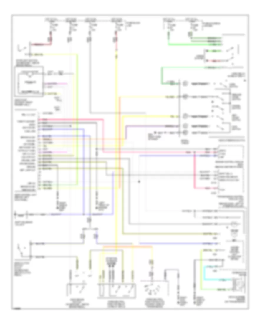
Cruise Control Wiring Diagram for Nissan Pathfinder SE 2001
List of elements for Cruise Control Wiring Diagram for Nissan Pathfinder SE 2001:
- (left front of engine) g110
- (right side of dash) g201
- 15u
- 17u
- 24u
- 39u
- A sol mon
- A/t
- Actr out (high)
- Air valve
- Air vlv out
- Ascd 4th cut sw
- Ascd brake switch (on bracket, above brake pedal)
- Ascd clutch switch (w:m/t) (on bracket, above clutch pedal)
- Ascd control unit (behind left kick panel)
- Ascd cruise sw
- Ascd pump (on right front fender well)
- Ascd steering switch
- Brake nc sw
- Brake no sw
- Cancel switch
- Combination meter
- Cruise
- Cruise lamp
- Cruise signal
- Dash) g201
- Engine control module (ecm) (behind center of dash)
- Fuse & fusible link box
- Fuse 10a
- Fuse 7.5a
- Fuse block (j/b)
- G201 (right side of dash)
- Gnd-c
- Ground
- Horn relay (in relay box 1)
- Horn switch
- Horns system
- Hot at all times
- Hot in on or start
- Ignition sw
- M/t
- M119
- M120
- M24
- M26
- Main sw
- Main switch
- Nca
- Od cancel
- Panel) g203
- Park/neutral position relay (in relay box 2)
- Park/neutral position switch (on right side of transmission)
- Pnk
- Red
- Rel vlv out
- Release valve
- Res/acc sw
- Resume/ accel switch
- Set
- Set lamp out
- Set/ coast switch
- Set/coast sw
- Shift sol a
- Shift solenoid valve a
- Spiral cable
- Starting charging system
- Stoplight switch (on bracket, above brake pedal)
- Throttle posit
- Transmission control module (tcm) (a/t) (behind dash, left of steering column)
- Tvo1
- Tvoo
- Unified meter control unit (w:odo/trip meter)
- Vac mtr out
- Vacuum motor
- Vehicle speed sensor (on transmission)
- Vsp
- Vsp (in)
 Čeština
 Dansk
Dansk Deutsch
 Ελληνικά
 English
 English
 Español
 Suomi
Suomi Français
 עברית
עברית Hrvatski
 Magyar
 Italiano
 日本語
日本語 한국어
한국어 Nederlands
 Polski
 Português
 Português
 Română
 Русский
 Slovenčina
 Slovenščina
 Svenska
 Türkçe
 中文 (中国)
 Français