EXTERIOR LIGHTS
Back-up Lamps Wiring Diagram, Evolution for Mitsubishi Lancer ES 2003
 https://portal-diagnostov.com/license.html
Automotive Electricians Portal FZCO
Automotive Electricians Portal FZCO
https://portal-diagnostov.com/license.html
https://portal-diagnostov.com/license.html
Automotive Electricians Portal FZCO
Automotive Electricians Portal FZCO
List of elements for Back-up Lamps Wiring Diagram, Evolution for Mitsubishi Lancer ES 2003:
- Back-up light switch (on top of transaxle)
- C210
- G8 (under rear seat back, at right upper corner of rear shelf panel)
- G9 (under rear seat back, at left upper corner of rear shelf panel)
- Hot in run or start
- Joint connector 4
- Junction block (behind left end of dash)
- Left back-up light
- Left rear combination light
- Multi- purpose fuse 3 7.5a
- Nca
- Red
- Right back-up light
- Right rear combination light
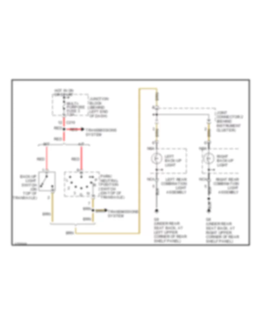
Back-up Lamps Wiring Diagram, Except Evolution for Mitsubishi Lancer ES 2003
List of elements for Back-up Lamps Wiring Diagram, Except Evolution for Mitsubishi Lancer ES 2003:
- A/t
- Back-up light switch (on top of transaxle)
- C210
- G8 (under rear seat back, at right upper corner of rear shelf panel)
- G9 (under rear seat back, at left upper corner of rear shelf panel)
- Hot in on or start
- Joint connector 2 (behind instrument cluster)
- Junction block (behind left end of dash)
- Left back-up light
- Left rear combination light assembly
- M/t
- Multi- purpose fuse 3 7.5a
- Nca
- Park/ neutral position switch (on top of transaxle)
- Red
- Right back-up light
- Right rear combination light assembly
- Transmissions system
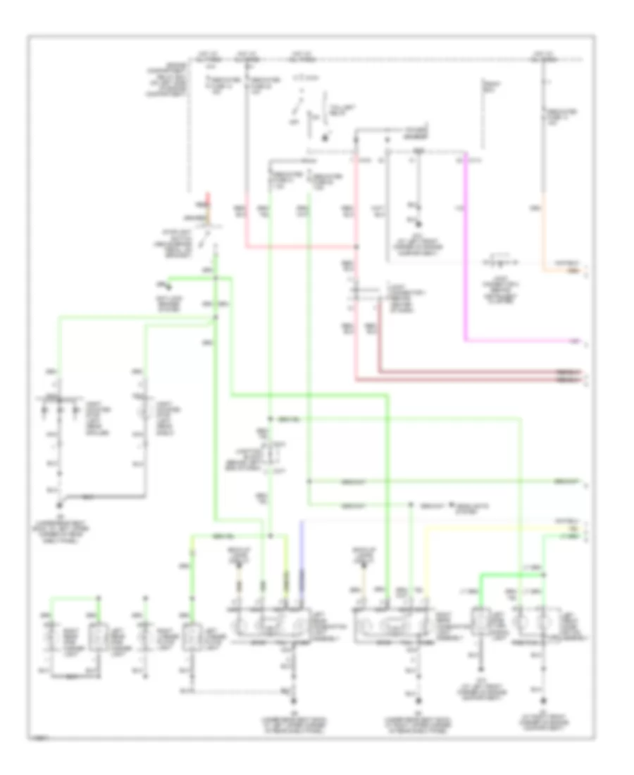
Exterior Lamps Wiring Diagram, Evolution (1 of 2) for Mitsubishi Lancer ES 2003
List of elements for Exterior Lamps Wiring Diagram, Evolution (1 of 2) for Mitsubishi Lancer ES 2003:
- A10x
- A11x
- Anti-lock brakes system
- Back-up lamps circuit
- C210
- C217
- Dedicated fuse 10 15a
- Dedicated fuse 13 10a
- Dedicated fuse 20 7.5a
- Dedicated fuse 21 7.5a
- Dedicated fuse 22 10a
- Engine compartment relay box (on left side of engine compartment)
- Front ecu
- G1 (at right front corner of engine compartment)
- G13 (at left front corner of engine compartment)
- G8 (under rear seat back, at right upper corner of rear shelf panel)
- G9 (under rear seat back, at left upper corner of rear shelf panel)
- Gnd
- Headlights system
- Hight mounted stop light (rear shelf)
- Hight mounted stop light (rear spoiler)
- Hot at all times
- Joint connector 1 (behind center of dash)
- Joint connector 2 (behind instrument cluster)
- Junction block (behind left end of dash)
- Left front combi- nation assembly
- Left license plate light
- Left rear combination light assembly turn
- Left rear side marker light
- Left side turn signal light
- Nca
- Off
- Position
- Power source
- Red
- Right license plate light
- Right rear combination light assembly turn
- Right rear side marker light
- Stop
- Stoplight switch (above brake pedal, on bracket)
- Tail
- Taillight relay
- Turn
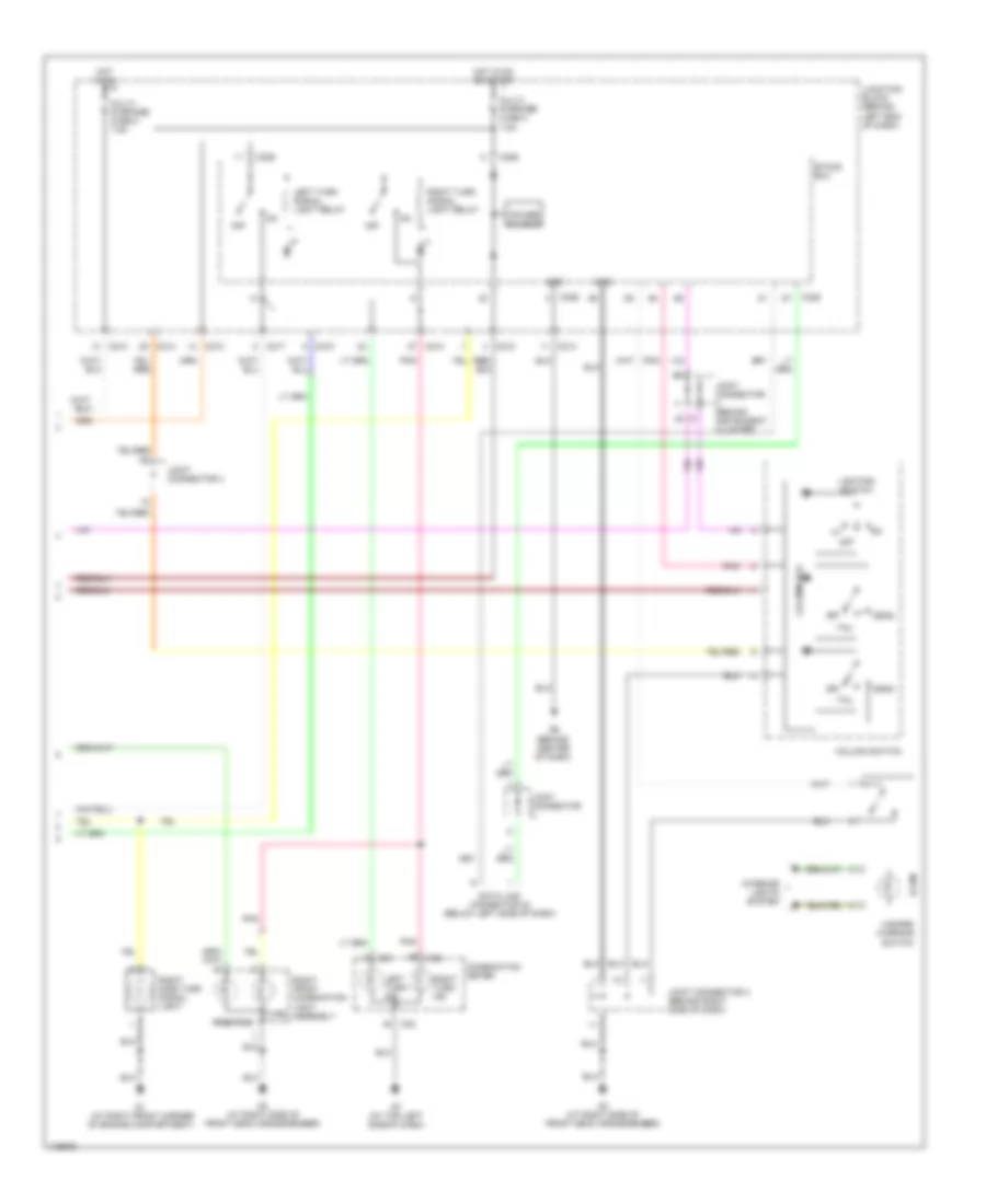
Exterior Lamps Wiring Diagram, Evolution (2 of 2) for Mitsubishi Lancer ES 2003
List of elements for Exterior Lamps Wiring Diagram, Evolution (2 of 2) for Mitsubishi Lancer ES 2003:
- (at right front corner of engine compartment)
- C01
- C02
- C210
- C214
- C217
- C226
- C228
- Column switch
- Column-ecu
- Combination meter
- Data link connector (2) (below left side of dash)
- Etacs ecu
- G3 (at right side of front deck crossmember)
- G6 (behind center of dash)
- G7 (at top left side of dash)
- Gnd
- Hazard warning switch
- Head
- Hot in on
- Hot in on or start
- Illum
- Interior lights system
- Joint connector
- Joint connector (behind instrument cluster)
- Joint connector 3 (behind right side of dash)
- Joint connector 4
- Junction block (behind left end of dash)
- Left turn ind
- Left turn signal light relay
- Lighting switch
- Multi- purpose fuse 2 7.5a
- Multi- purpose fuse 5 7.5a
- Off
- Pnk
- Position
- Power source
- Right front combination light assembly
- Right side turn signal light
- Right turn ind
- Right turn signal light relay
- Tail
- Turn
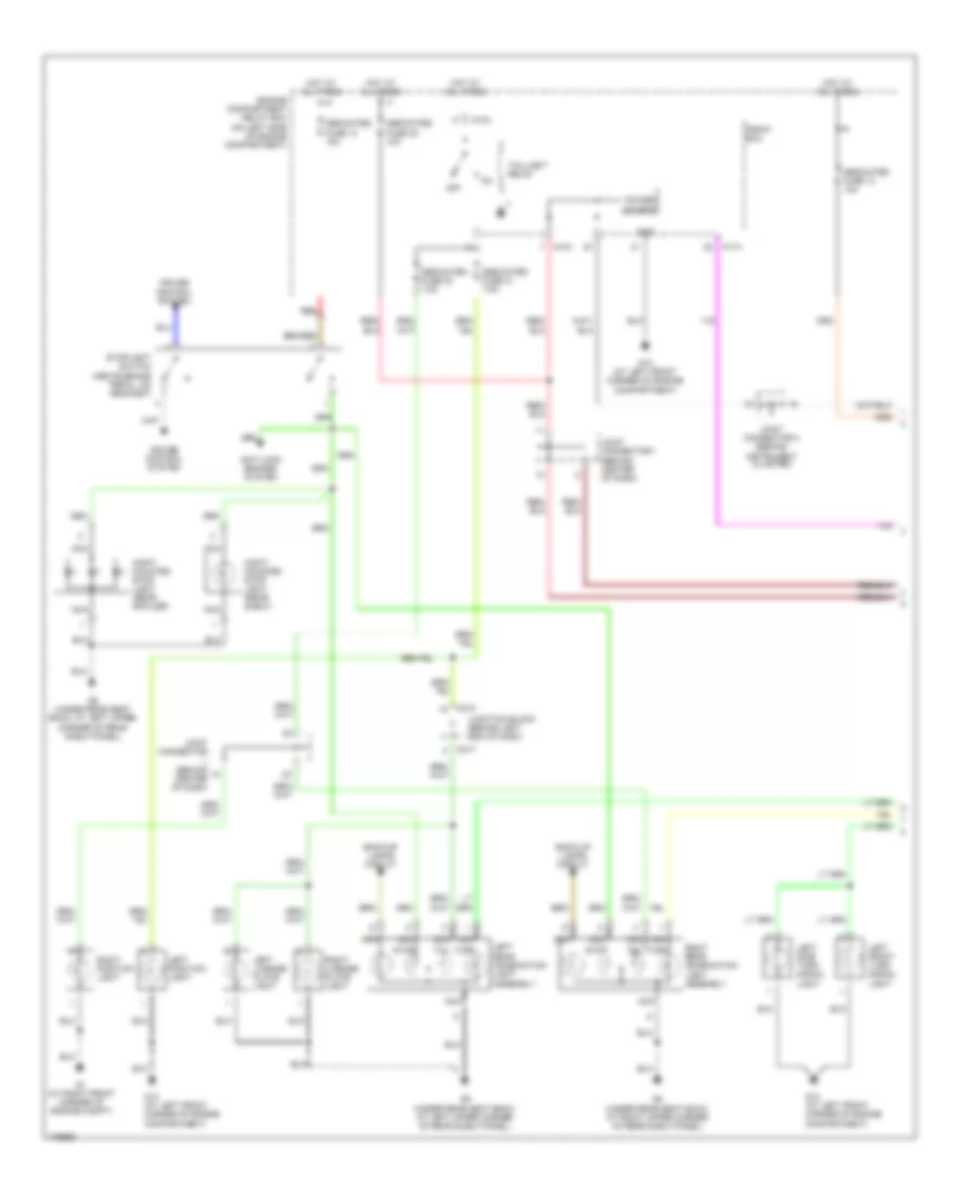
Exterior Lamps Wiring Diagram, Except Evolution (1 of 2) for Mitsubishi Lancer ES 2003
List of elements for Exterior Lamps Wiring Diagram, Except Evolution (1 of 2) for Mitsubishi Lancer ES 2003:
- A10x
- A11x
- Anti-lock brakes system
- Back-up lamps circuit
- C210
- C217
- Cruise control system
- Dedicated fuse 10 15a
- Dedicated fuse 13 10a
- Dedicated fuse 20 7.5a
- Dedicated fuse 21 7.5a
- Dedicated fuse 22 10a
- Engine compartment relay box (on left side of engine compartment)
- Front ecu
- G1 (at right front corner of engine compt)
- G13 (at left front corner of engine compartment)
- G8 (under rear seat back, at right upper corner of rear shelf panel)
- G9 (under rear seat back, at left upper corner of rear shelf panel)
- Gnd
- Hight mounted stop light (rear shelf)
- Hight mounted stop light (rear spoiler)
- Hot at all times
- Joint connector (behind center of dash)
- Joint connector 1 (behind center of dash)
- Joint connector 2 (behind instrument cluster)
- Junction block (behind left end of dash)
- Left front turn signal light
- Left license plate light
- Left position light
- Left rear combination light assembly
- Left side turn signal light
- Nca
- Off
- Power source
- Red
- Right license plate light
- Right position light
- Right rear combination light assembly
- Stop
- Stoplight switch (above brake pedal, on bracket)
- Tail
- Taillight relay
- Turn
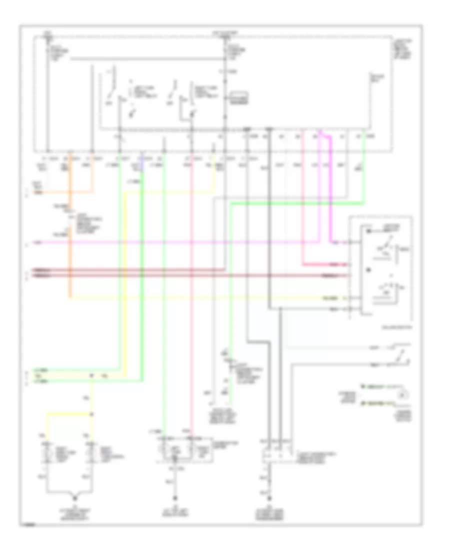
Exterior Lamps Wiring Diagram, Except Evolution (2 of 2) for Mitsubishi Lancer ES 2003
List of elements for Exterior Lamps Wiring Diagram, Except Evolution (2 of 2) for Mitsubishi Lancer ES 2003:
- C01
- C02
- C210
- C214
- C217
- C226
- C228
- Column switch
- Combination meter
- Data link connector (2) (below left side of dash)
- Etacs ecu
- G1 (at right front corner of engine compt)
- G3 (at right side of front deck crossmember)
- G7 (at top left side of dash)
- Gnd
- Hazard warning switch
- Head
- Hot in on
- Hot in start or on
- Interior lights system
- Joint connector 2 (behind instrument cluster)
- Joint connector 3 (behind right side of dash)
- Joint connector 5 (behind instrument cluster)
- Junction block (behind left end of dash)
- Left turn ind
- Left turn signal light relay
- Lighting switch
- Multi- purpose fuse 2 7.5a
- Multi- purpose fuse 5 7.5a
- Off
- Pnk
- Power source
- Right front turn signal light
- Right side turn signal light
- Right turn ind
- Right turn signal light relay
- Tail

 Čeština
 Dansk
Dansk Deutsch
 Ελληνικά
 English
 English
 Español
 Suomi
Suomi Français
 עברית
עברית Hrvatski
 Magyar
 Italiano
 日本語
日本語 한국어
한국어 Nederlands
 Polski
 Português
 Português
 Română
 Русский
 Slovenčina
 Slovenščina
 Svenska
 Türkçe
 中文 (中国)