STARTING/CHARGING
Charging Wiring Diagram for Suzuki XL7 Luxury 2007
 https://portal-diagnostov.com/license.html
Automotive Electricians Portal FZCO
Automotive Electricians Portal FZCO
https://portal-diagnostov.com/license.html
https://portal-diagnostov.com/license.html
Automotive Electricians Portal FZCO
Automotive Electricians Portal FZCO
List of elements for Charging Wiring Diagram for Suzuki XL7 Luxury 2007:
- (center of dash, beneath right side of radio) i/p fuse block
- 200a
- Battery
- Battery current sensor (under underhood fuse block)
- Body control module (bcm) (center of dash, behind hvac control module)
- Charge ind
- Class 2 (pcm)
- Class 2 serial data
- Computer data lines system
- Current sens
- Cycle sig
- Ecm bat fuse 33 15a
- Engine control module (ecm) (mounted on top of battery cover)
- G103 (at left side of engine compt)
- G105 (at lower right rear of engine)
- Generator
- Generator fuse
- Gnd
- Hot at all times
- Hot w/ ign main relay 31 energized
- Ign
- Instrument panel cluster (ipc)
- Logic
- Low ref
- On sig
- Pnk
- Pos volt
- Positive volt
- Power distribution system
- Red
- Rvc fuse 10a
- Sens sig
- Serial data
- Serial data (+)
- Serial data (-)
- Sir disply fuse 25 10a
- Sply volt
- Starter
- Tan
- Underhood fuse block (left side of engine compt)
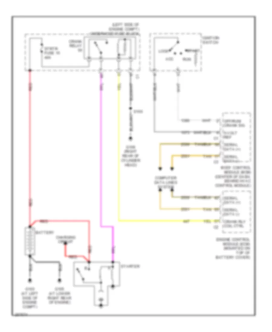
Starting Wiring Diagram for Suzuki XL7 Luxury 2007
List of elements for Starting Wiring Diagram for Suzuki XL7 Luxury 2007:
- (left side of engine compt) underhood fuse block
- 5-volt ref
- Acc
- Battery
- Body control module (bcm) (center of dash, behind hvac control module)
- Charging circuit
- Computer data lines system
- Crank relay
- Crank rly coil ctrl
- Engine control module (ecm) (mounted on top of battery cover)
- G103 (at left side of engine compt)
- G105 (at lower right rear of engine)
- G109 (right rear of cylinder head)
- Ignition switch
- Lock
- Off/run/ crank sig
- Red
- Run
- S100
- Serial data (+)
- Serial data (-)
- Start
- Starter
- Strtr fuse 15 40a
- Tan

 Čeština
 Dansk
Dansk Deutsch
 Ελληνικά
 English
 English
 Español
 Suomi
Suomi Français
 עברית
עברית Hrvatski
 Magyar
 Italiano
 日本語
日本語 한국어
한국어 Nederlands
 Polski
 Português
 Português
 Română
 Русский
 Slovenčina
 Slovenščina
 Svenska
 Türkçe
 中文 (中国)