
 Čeština
 Dansk
Dansk Deutsch
 Ελληνικά
 English
 English
 Español
 Suomi
Suomi Français
 עברית
עברית Hrvatski
 Magyar
 Italiano
 日本語
日本語 한국어
한국어 Nederlands
 Polski
 Português
 Português
 Română
 Русский
 Slovenčina
 Slovenščina
 Svenska
 Türkçe
 中文 (中国)

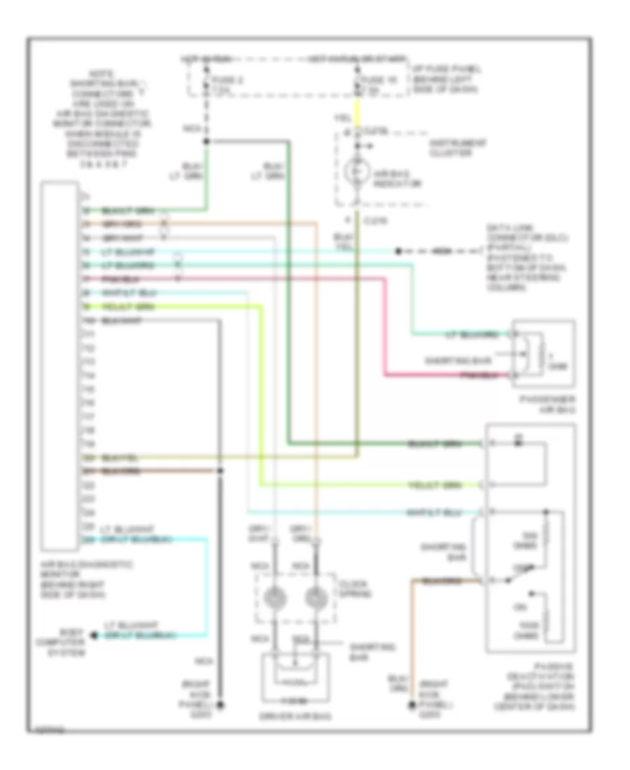
SUPPLEMENTAL RESTRAINTS
Supplemental Restraint Wiring Diagram for Mazda B4000 SE 2000
List of elements for Supplemental Restraint Wiring Diagram for Mazda B4000 SE 2000:

AIR CONDITIONINGANTI-LOCK BRAKESANTI-THEFTCOMPUTER DATA LINESENGINE PERFORMANCEBODY COMPUTERGROUND DISTRIBUTIONEXTERIOR LIGHTSCRUISE CONTROLINSTRUMENT CLUSTERHEADLIGHTSHORNPOWER DISTRIBUTIONINTERIOR LIGHTSPOWER DOOR LOCKSPOWER WINDOWSSUPPLEMENTAL RESTRAINTSRADIOSHIFT INTERLOCKSPOWER MIRRORSTRANSMISSIONWARNING SYSTEMSSTARTING/CHARGINGWIPER/WASHER