AIR CONDITIONING
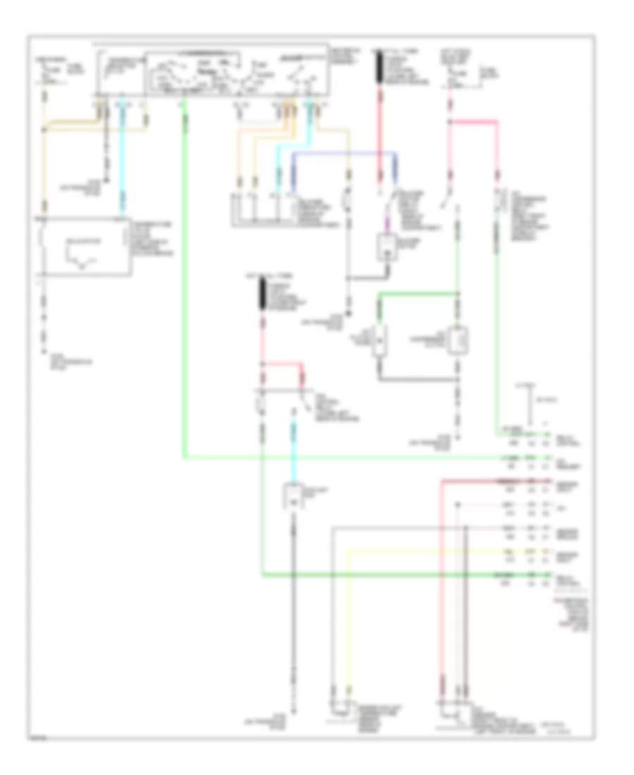
Air Conditioning Wiring Diagrams for Chevrolet Beretta 1995
List of elements for Air Conditioning Wiring Diagrams for Chevrolet Beretta 1995:
- (l4 vin 4)
- (v6 vin m)
- +5v
- A/c clutch diode
- A/c compressor clutch
- A/c compressor control relay (right front of engine compartment on relay bracket)
- A/c request
- A/c sensor (right front of engine compartment) (left front of engine)
- Bi-lv
- Blend
- Blower motor
- Blower motor relay (right rear of engine compartment)
- Blower resistors (rear of engine compartment)
- Blower switch
- C tan
- C10
- C11
- Coolant fan
- D12
- Def
- Engine coolant temperature sensor (rear of engine)
- Fan control relay (lower left rear of engine)
- Fuse 20a
- Fuse 25a
- Fuse block
- G129 (on transaxle stud)
- Heater-a/c control assembly
- Hot at all times
- Hot in run
- Hot in run, bulb test or start
- Htr
- L4 vin 4
- Max
- Mode switch
- Norm
- Off
- Pnk
- Powertrain control module (behind right side of i/p)
- Red
- Relay control
- Sensor ground
- Sensor input
- Solid state
- Tan
- Temperature selector
- Temperature valve motor (left side of steering column brace)
- V6 vin m
- Vent
 Čeština
 Dansk
Dansk Deutsch
 Ελληνικά
 English
 English
 Español
 Suomi
Suomi Français
 עברית
עברית Hrvatski
 Magyar
 Italiano
 日本語
日本語 한국어
한국어 Nederlands
 Polski
 Português
 Português
 Română
 Русский
 Slovenčina
 Slovenščina
 Svenska
 Türkçe
 中文 (中国)
 Français