AIR CONDITIONING
Compressor Wiring Diagram for Chevrolet Metro LSi 1999
 https://portal-diagnostov.com/license.html
Automotive Electricians Portal FZCO
Automotive Electricians Portal FZCO
https://portal-diagnostov.com/license.html
https://portal-diagnostov.com/license.html
Automotive Electricians Portal FZCO
Automotive Electricians Portal FZCO
List of elements for Compressor Wiring Diagram for Chevrolet Metro LSi 1999:
- (i/p harness, 8 cm from blower motor breakout)
- A/c 1 relay
- A/c 2 relay
- A/c compressor clutch
- A/c compressor control module (below right side of dash, on evaporator case)
- A/c fuse 15a
- A/c off
- A/c refrigerant temperature switch (behind right side of dash)
- A/c relay
- A/c req
- A/c switch
- Blower speed selector switch
- Dual pres sw
- Dual pressure switch (right side of engine compartment, near strut tower)
- Evap temp
- Fuse box
- G103 (right front of engine compt)
- Heater fuse 20a
- Hot at all times
- Hot in on
- Junction block
- Off
- Pnk
- Powertrain control module (pcm) (behind right side of dash)
- Relay box
- S122 (main harn, at relay box)
- S134 (a/c jumper harn, right front of engine compartment)
- S233
- Sensor ground
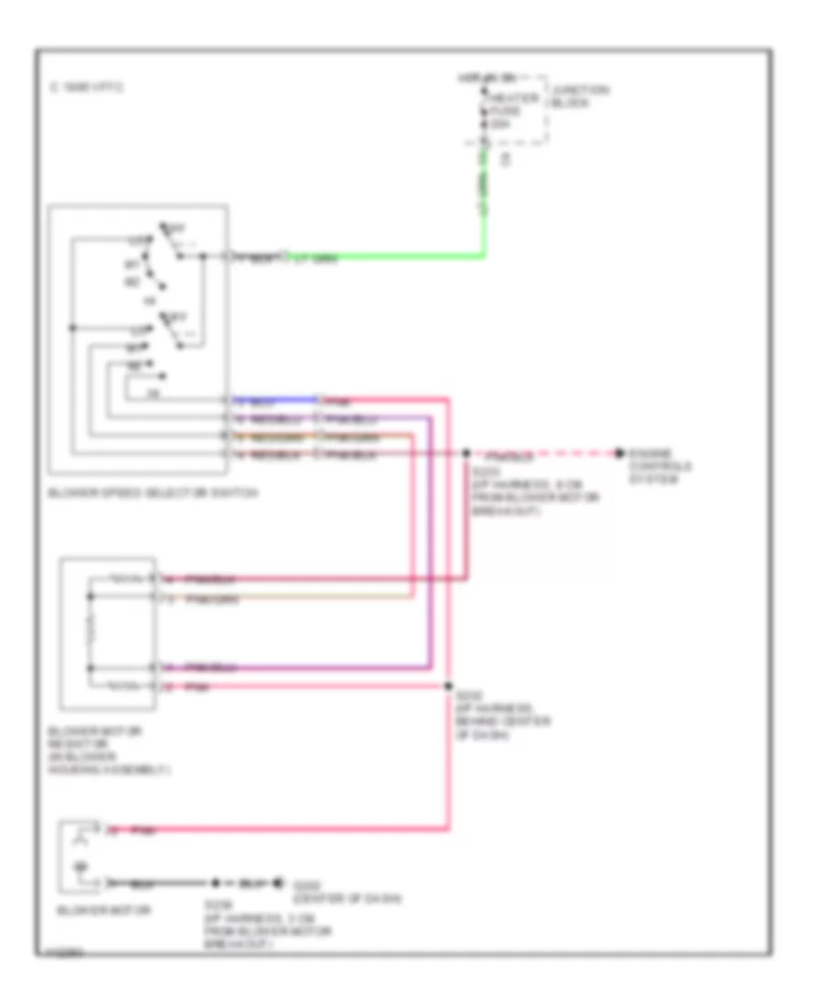
Heater Wiring Diagram for Chevrolet Metro LSi 1999
List of elements for Heater Wiring Diagram for Chevrolet Metro LSi 1999:
- 1995 vftc c
- Blower motor
- Blower motor resistor (in blower housing assembly)
- Blower speed selector switch
- Engine controls system
- G202 (center of dash)
- Heater fuse 20a
- Hot in on
- Junction block
- Off
- Pnk
- S232 (i/p harness, behind center of dash)
- S233 (i/p harness, 8 cm from blower motor breakout)
- S238 (i/p harness, 3 cm from blower motor breakout)
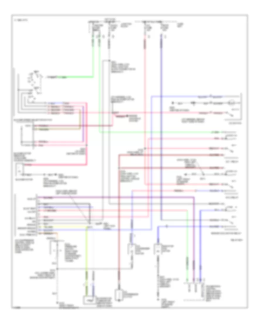
Manual A/C Wiring Diagram for Chevrolet Metro LSi 1999
List of elements for Manual A/C Wiring Diagram for Chevrolet Metro LSi 1999:
- (i/p harness, 8 cm from blower motor breakout)
- (i/p harness, behind right side of dash)
- (main harn, 18 cm from left firewall grommet)
- (main harn, behind left side of dash)
- 1995 vftc c
- A/c 1 relay
- A/c 2 relay
- A/c compressor clutch
- A/c compressor control module (below right side of dash, on evaporator case)
- A/c condenser fan motor
- A/c fuse 15a
- A/c off
- A/c relay
- A/c req
- A/c switch
- Blower motor
- Blower motor resistor (in blower housing assembly)
- Blower speed selector switch
- Dual pres sw
- Dual pressure switch (right side of engine compartment, near strut tower)
- Engine controls system
- Engine cooling fan relay
- Evap temp
- Evaporator thermistor (behind right side of dash)
- Fuse box
- G102 (left front of engine compt)
- G103 (right front of engine compt)
- G201 (left kick panel)
- G202 (center of dash)
- Ground
- Heater fuse 20a
- Hot at all times
- Hot in on
- Hot in on or start
- Idle up
- Idle-up
- Ig-coil fuse 15a
- Ign
- Junction block
- Off
- Pnk
- Powertrain control module (pcm) (behind right side of dash, near glove box)
- Radiator fan motor
- Rdtr fuse 30a
- Relay box
- Relay ctrl
- S122 (main harn, at relay box)
- S123 (main harn, 4 cm from ignition control module breakout)
- S134 (a/c jumper harn, right front of engine compartment)
- S210
- S213
- S231 (main harn, 8 cm from junction block connector c6 breakout)
- S232 (i/p harn, center of dash)
- S233
- S238 (i/p harness, 3 cm from blower motor breakout)
- S247 (main harn, 18 cm from left firewall grommet)
- S254
- Sensor ground

 Čeština
 Dansk
Dansk Deutsch
 Ελληνικά
 English
 English
 Español
 Suomi
Suomi Français
 עברית
עברית Hrvatski
 Magyar
 Italiano
 日本語
日本語 한국어
한국어 Nederlands
 Polski
 Português
 Português
 Română
 Русский
 Slovenčina
 Slovenščina
 Svenska
 Türkçe
 中文 (中国)