ANTI-THEFT
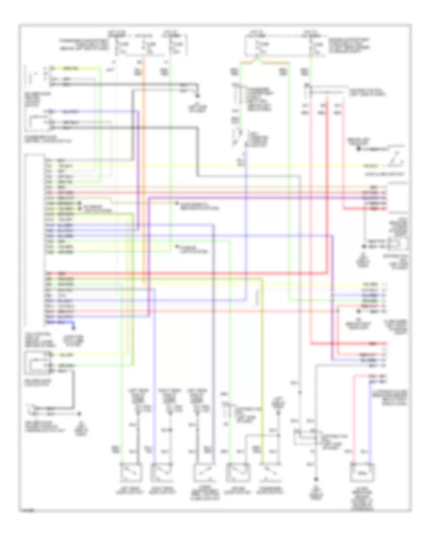
Anti-theft Alarm Wiring Diagram for Volvo V40 2002
List of elements for Anti-theft Alarm Wiring Diagram for Volvo V40 2002:
- (behind left headlamp) g8
- (left rear side of cargo compt) g10 g12
- (left side of dash) g1
- (right rear side of cargo compt) g11 g12
- (s40) (v40)
- A10
- A12
- A13
- A16
- A18
- A19
- A20
- A22
- A23
- A24
- A26
- Alarm siren (left front of engine compt)
- B10
- B11
- B14
- B15
- B16
- B19
- C10
- Cargo compartment area, lighting/ alarm contact
- Computer data lines system
- Distribution rail (left side of dash)
- Driver door contact
- Driver's door central locking switch
- Driver's door lock switch
- Driver's door power windows/ mirrors switch unit
- E10
- Engine compartment fuse & relay box (in left rear corner of engine compt)
- Exterior lights system
- F10
- Fuse 10a
- Fuse 15a
- Fuse 20a
- G1 (left side of dash)
- G15
- G9 (behind right headlamp)
- Glass breakage sensor (on roof, at center of windshield)
- Hood alarm contact
- Hot at all times
- Hot in on
- Hot in on or start
- Interior lights system
- Key- inserted warning contact
- Left rear door contact
- Passenger compartment fuse & relay box (behind left end of dash)
- Passenger door central locking switch
- Passenger door contact
- Pnk
- Red
- Right rear door contact
- Ultrasonic glass breakage sensor (below right side of dash)
- Vgla control module (behind lower center of dash)
- Vgla receiver (in rear of engine compt)
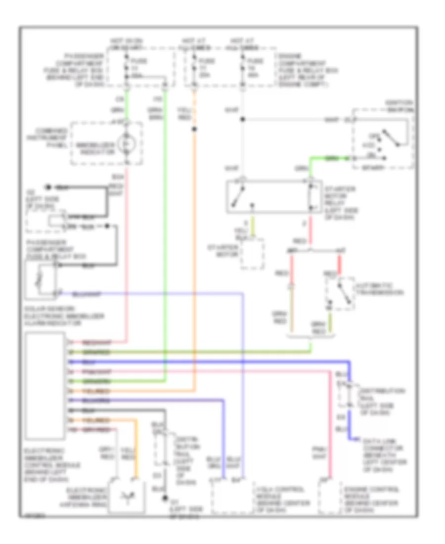
Immobilizer Wiring Diagram for Volvo V40 2002
List of elements for Immobilizer Wiring Diagram for Volvo V40 2002:
- (left side of dash)
- A/t
- A11
- A17
- Acc
- Automatic transmission
- B24
- Combined instrument panel
- Data link connector (beneath left center of dash)
- Distri- bution rail (left side of dash)
- Distribution rail (left side of dash)
- Electronic immobilizer antenna ring
- Electronic immobilizer control module (behind left end of dash)
- Engine compartment fuse & relay box (left rear of engine compt)
- Engine control module (behind center of dash)
- Fuse 10a
- Fuse 20a
- Fuse 40a
- Hot at all times
- Hot in on or start
- I15
- Ignition switch
- Immobilizer indicator
- M/t
- Off
- Passenger compartment fuse & relay box
- Passenger compartment fuse & relay box (behind left end of dash)
- Red
- Solar sensor/ electronic immobilizer alarm indicator
- Start
- Starter motor
- Starter motor relay (left side of dash)
- Vgla control module (behind center of dash)
 Čeština
 Dansk
Dansk Deutsch
 Ελληνικά
 English
 English
 Español
 Suomi
Suomi Français
 עברית
עברית Hrvatski
 Magyar
 Italiano
 日本語
日本語 한국어
한국어 Nederlands
 Polski
 Português
 Português
 Română
 Русский
 Slovenčina
 Slovenščina
 Svenska
 Türkçe
 中文 (中国)

 Français