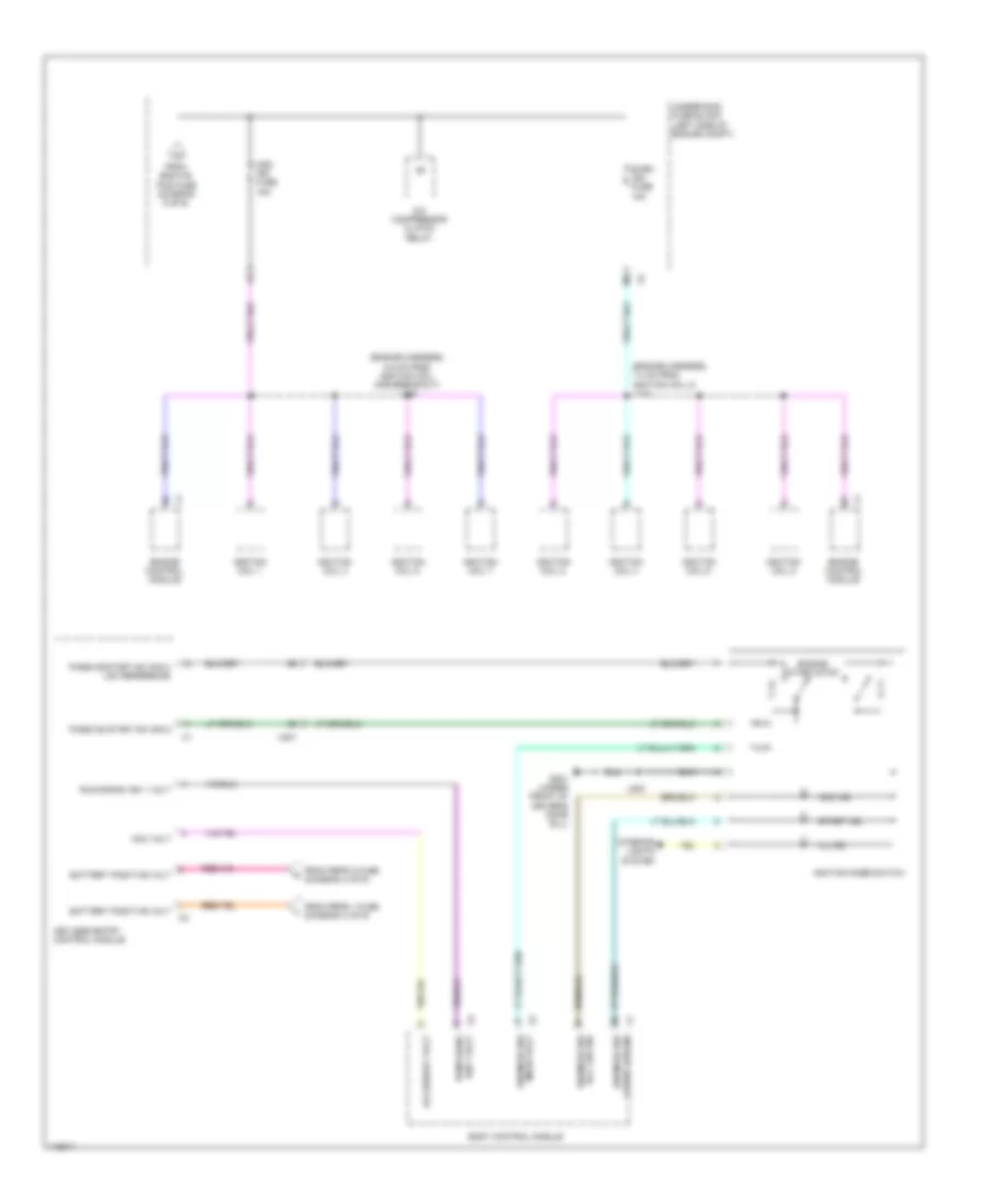
POWER DISTRIBUTION
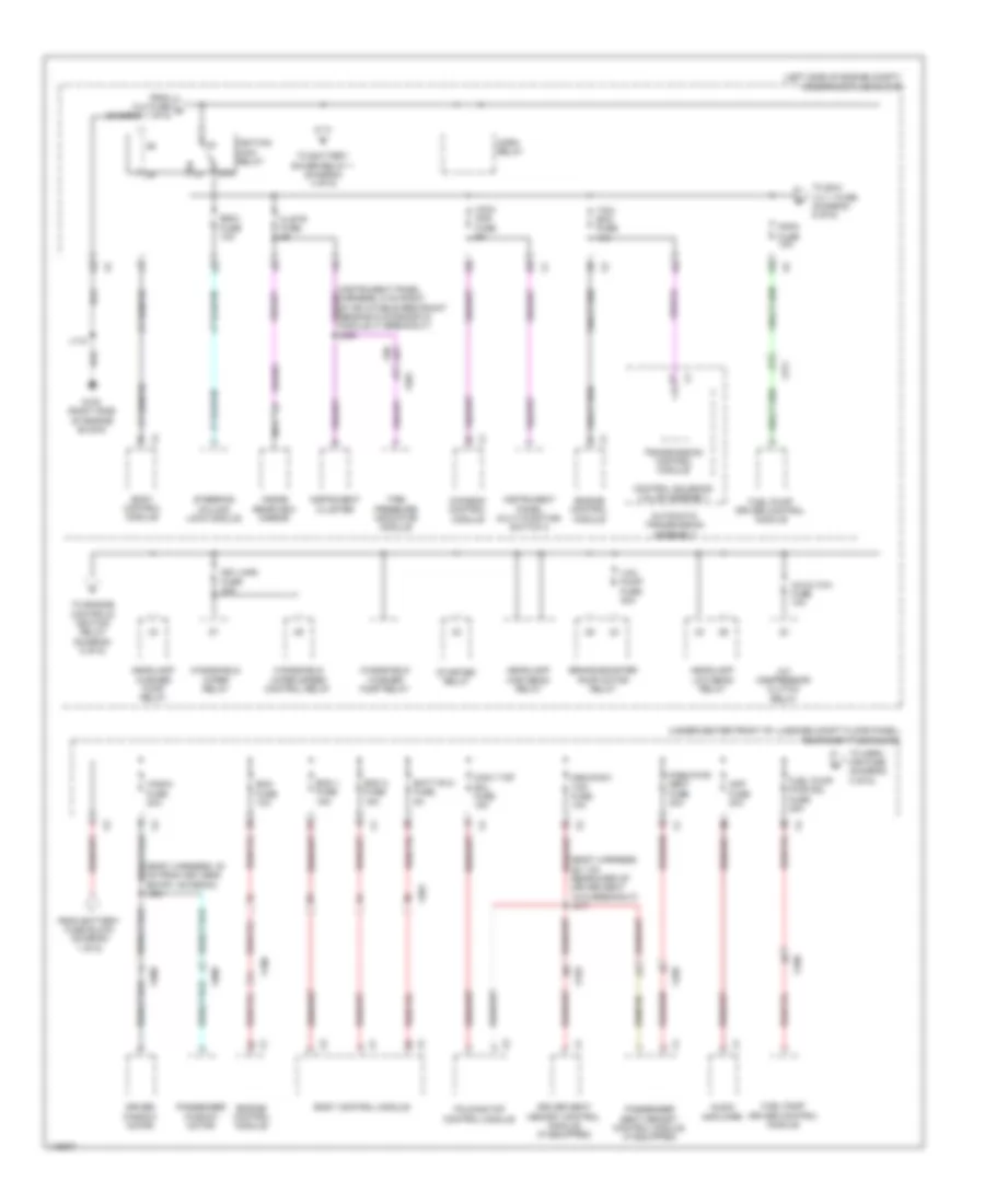
Power Distribution Wiring Diagram (1 of 6) for Chevrolet Corvette Stingray 2014
 https://portal-diagnostov.com/license.html
Automotive Electricians Portal FZCO
Automotive Electricians Portal FZCO
https://portal-diagnostov.com/license.html
https://portal-diagnostov.com/license.html
Automotive Electricians Portal FZCO
Automotive Electricians Portal FZCO
List of elements for Power Distribution Wiring Diagram (1 of 6) for Chevrolet Corvette Stingray 2014:
- (left side of engine compt) underhood fuse block
- (not used)
- Abs pump fuse 60a
- Abs vlv fuse 30a
- Automatic transmission assembly
- Auxiliary underhood fuse block (near underhood fuse block)
- Battery
- Battery fuse block (on battery positive (+) post)
- Bcm 5 fuse 10a
- Bcm 6 fuse 10a
- Bcm 7 fuse 10a
- Blower motor control module
- Body control module
- Clm fuse 10a
- Cnstr vent fuse 10a
- Control solenoid valve assembly
- Cooling fan control module
- Data link connector
- Dlc fuse 10a
- Elec prk/brk fuse 30a
- Elec rear diff mdl fuse 40a
- Electronic brake control module
- Evaporative emission vent solenoid valve
- Folding top pump motor assembly
- Folding top pump motor relay 1
- Folding top pump motor relay 2
- Frt hvac fuse 40a
- Fuse 100a
- Fuse 225a
- Fuse 350a
- Fuse 60a
- Fuse 80a
- Generator
- Htd/ seat 1 fuse 15a
- Hvac cntrl fuse 15a
- Hvac control module
- J346 (chassis harness, 16 cm from main harness on transmission cooling fan breakout)
- J401 (body harness, 6 cm from fuse block & battery x2, x3 & x4 breakouts)
- J414
- M/t
- Nca
- Park brake control module
- Power steering control module
- Rear differential clutch control module
- Red
- Rev lkout fuse 10a
- Reverse inhibit solenoid actuator
- Rtd fuse 30a
- Seat heating control module
- Starter motor
- Steering column lock module
- Steering column position control module
- Strg col fuse 20a
- Suspension control module (if equipped)
- Tcm fuse 15a
- To ignition main relay (diagram 2 of 6)
- To rear body fuse block (diagram 2 of 6)
- To rear body fuse block (diagram 3 of 6)
- Trans cool fan fuse 20a
- Transmission control module
- Transmission cooling fan module (w/ hd cooling system transmission)
- Used) (not
- X201
- X311
- X312
- X313
- X320
- X403
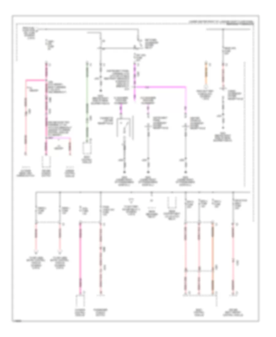
Power Distribution Wiring Diagram (2 of 6) for Chevrolet Corvette Stingray 2014
List of elements for Power Distribution Wiring Diagram (2 of 6) for Chevrolet Corvette Stingray 2014:
- (body harness, 28.1 cm rearward of driver seat x310 breakout) j317
- (body harness, 30 cm from keyless entry antenna) j321
- (left side of engine compt) underhood fuse block
- (under center front of luggage compt floor panel) rear body fuse block
- 87a
- A/c cltch fuse 10a
- A/c compressor clutch relay
- Amp fuse 30a
- Audio amplifier
- Automatic transmission assembly
- Batt rvc fuse 5a
- Bcm 1 fuse 15a
- Bcm 3 fuse 15a
- Body control module
- Brake booster pump motor relay
- Chassis control module
- Clstr fuse 5a
- Control solenoid valve assembly
- Conv top sol fuse 15a
- Driver seat memory control module (if equipped)
- Driver window motor
- Ecm fuse 10a
- Engine control module
- Escl fuse 10a
- Folding top control module
- Fppm fuse 10a
- From battery fuse block (diagram 1 of 6)
- From clm fuse a (diagram 1 of 6)
- Frt wpr fuse 30a
- Fuel pump driver control module
- Fuel pump pwr mdl fuse 25a
- G100 (right side of engine block)
- Headlamp high beam relay
- Headlamp low beam relay
- Headlamp washer pump relay
- Horn relay
- Iccm/ aos fuse 5a
- Ignition main relay
- Inside rearview mirror
- Instrument cluster
- Instrument panel multi-function switch 2
- J118
- Msm/conv top fuse 10a
- Nca
- Pass pwr seat fuse 30a
- Passenger seat memory control module (if equipped)
- Passenger window motor
- Starter relay
- Steering column lock module
- Tcm/ ecm fuse 15a
- Tire pressure indicator module
- To battery saver relay 1 (diagram 4 of 6)
- To engine controls ignition relay (diagram 5 of 6)
- To exh vlv 1 fuse (diagram 5 of 6)
- To osrv mir fuse (diagram 3 of 6)
- Transmission control module
- Vac pump fuse 30a
- Windshield washer pump relay
- Windshield wiper relay
- Windshield wiper speed control relay
- Wndw fuse 30a
- X100
- X201
- X310
- X311
- X320
- X350
- X500
- X600
Power Distribution Wiring Diagram (3 of 6) for Chevrolet Corvette Stingray 2014
List of elements for Power Distribution Wiring Diagram (3 of 6) for Chevrolet Corvette Stingray 2014:
- (body harness, 11 cm into x500 breakout)
- (driver door trim harness, 5.7 cm into main breakout leading to mirror control module) (w/ memory) j503
- (instrument panel harness, 5 cm into inflatable restraint sensing & diagnostic module x1 breakout) j210
- (under center front of luggage compt floor panel) rear body fuse block
- Bcm 2 fuse 15a
- Bcm 4 fuse 15a
- Bcm 8 fuse 30a
- Body control module
- Cargo accessory power receptacle
- Center console accessory power receptacle
- Chassis control module
- Cigarette lighter receptacle
- Driver seat memory control module
- Driver window switch
- Drvr pwr seat fuse 30a
- From battery fuse block (diagram 1 of 6)
- From fuel pump pwr g mdl fuse (diagram 2 of 6)
- Frt apo fuse 20a
- G202 (under front of passenger's door sill)
- G403 (behind right side of rear bumper fascia)
- Iccm fuse 15a
- Instrument panel accessory power receptacle
- J206
- J403
- Mirror control module
- Osrv mir fuse 5a
- Outside rear view mirror switch
- Pass wndw sw fuse 10a
- Passenger window switch
- Peps 1 fuse 10a
- Peps 2 fuse 30a
- Rear apo fuse 30a
- Rear compartment lid unlatch relay
- Rear defogger relay
- Retained accessory power relay
- To battery saver relay 2 (diagram 4 of 6)
- To keyless entry control module (diagram 6 of 6)
- W/ memory
- W/ smokers package accessory
- W/o smokers package accessory
- X201
- X310
- X500
- X515
- X600
- X615
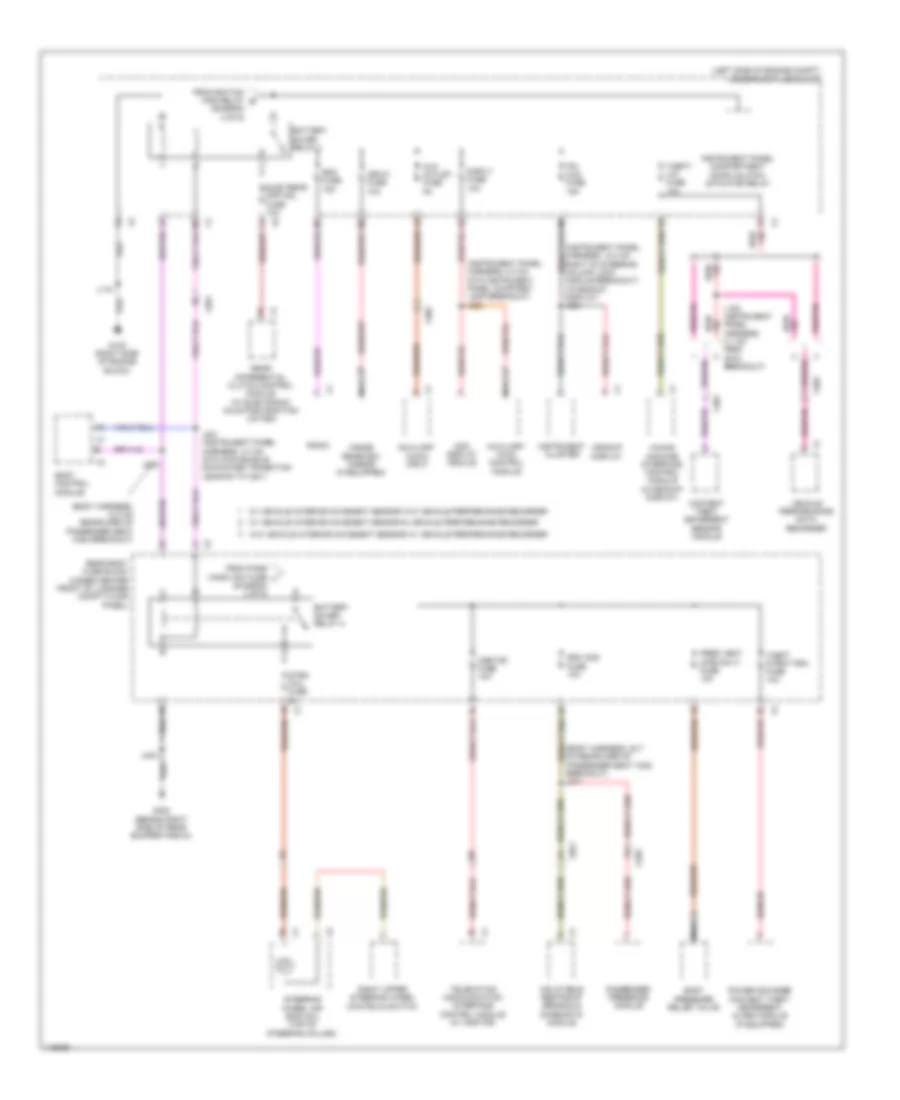
Power Distribution Wiring Diagram (4 of 6) for Chevrolet Corvette Stingray 2014
List of elements for Power Distribution Wiring Diagram (4 of 6) for Chevrolet Corvette Stingray 2014:
- (body harness, 12.2 cm rearward of passenger seat x320 breakout)
- (body harness, 22.7 cm rearward of passenger seat x320 breakout) j311
- (diagram 2 of 6)
- (diagram 3 of 6)
- (instrument panel harness, 12.3 cm right of steering column lock module breakout) (w/headup display) j204
- (instrument panel harness, 5.3 cm into instrument panel courtesy lamp breakout) j223
- (left side of engine compt) underhood fuse block
- Aux outlet fuse 5a
- Auxiliary audio input
- Auxiliary hvac control module
- Battery saver relay 1
- Battery saver relay 2
- Body control module
- Body pressure relief valve
- Content theft deterrent sensor module
- Disply fuse 10a
- Elec rear diff mdl fuse 10a
- From ignition main relay e
- From pass wndw sw fuse j
- G100 (right side of engine block)
- G403 (behind right side of rear bumper fascia)
- Headup display
- Human machine interface control module (w/headup display)
- Inflatable restraint sensing & diagnostic module
- Info display module
- Inside rearview mirror (if equipped)
- Instrument cluster
- Instrument panel compartment door unlatch actuator relay
- Ipc hud fuse 15a
- Isrvm fuse 10a
- J105 (instrument panel harness, 4.1 cm from g105 breakout)
- J118
- J221 (instrument panel harness, 3.3 cm into main bundle downward transition leading to x201)
- J309
- J403
- Nca
- Onstar fuse 10a
- Passenger presence module
- Power sounder content theft deterrent alarm module (if equipped)
- Pres vent (cpe only) fuse 10a
- Radio
- Rdo fuse 15a
- Rear body fuse block (under center front of luggage compt floor panel)
- Rear differential clutch control module (w/ electronic axle positraction limited)
- Right upper steering wheel controls switch
- Sdm aos fuse 10a
- Steering wheel air bag coil (top of steering column)
- Strg whl fuse 2a
- Telematics communication interface control module (w/ onstar)
- Theft dtrnt psm fuse 10a
- Theft/ vim fuse 10a
- Vehicle performance data recorder
- W/ vehicle interior movement sensor & vehicle performance recorder
- W/ vehicle interior movement sensor w/o vehicle performance recorder
- W/o vehicle interior movement sensor w/ vehicle performance recorder
- X201
- X202
- X301
- X302
- X320
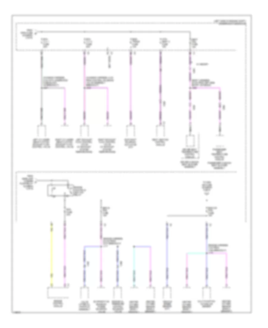
Power Distribution Wiring Diagram (5 of 6) for Chevrolet Corvette Stingray 2014
List of elements for Power Distribution Wiring Diagram (5 of 6) for Chevrolet Corvette Stingray 2014:
- (body harness, 20 cm from keyless entry antenna) j322
- (chassis harness, 5 cm from control solenoid valve assembly breakout) j343
- (chassis harness, 5 cm into underhood fuse block x5 breakout) j341
- (diagram 2 of 6)
- (engine harness, 4 cm from x160 breakout) j115
- (engine harness, 6.8 cm from g107 breakout) j117
- (left side of engine compt) underhood fuse block
- (not used)
- Controls ignition relay
- Driver cushion seat blower assembly
- Driver seat temperature control module
- Ecm fuse 30a
- Eng is pos fuse 15a
- Eng o/s pos fuse 15a
- Eng/ trans fuse 10a
- Engine
- Engine control module
- Engine oil pressure control solenoid valve
- Evaporative emission purge solenoid valve
- Exh vlv 1 fuse 20a
- Exh vlv 2 fuse 20a
- From fppm fuse b
- From headlamp washer c pump relay (diagram 2 of 6)
- Heated oxygen sensor bank 1 sensor 1
- Heated oxygen sensor bank 1 sensor 2
- Heated oxygen sensor bank 2 sensor 1
- Heated oxygen sensor bank 2 sensor 2
- Htd/ seat 2 fuse 15a
- Left cylinder deactivation exhaust flow control valve
- Left exhaust flow control valve (w/ exhaust system performance)
- Multi-function intake air sensor
- Nca
- Passenger cushion seat blower assembly
- Passenger seat temperature control module
- Right cylinder deactivation exhaust flow control valve
- Right exhaust flow control valve (w/ exhaust system performance)
- Seat fan fuse 15a
- Seat heating control module
- Skip shift solenoid actuator (m/t)
- To odd ign fuse (diagram 6 of 6)
- Valve lifter oil manifold assembly
- Vehicle speed sensor (m/t)
- W/ memory
- X106
- X107
- X201
- X310
- X320
Power Distribution Wiring Diagram (6 of 6) for Chevrolet Corvette Stingray 2014
List of elements for Power Distribution Wiring Diagram (6 of 6) for Chevrolet Corvette Stingray 2014:
- (engine harness, 7.4 cm from ignition coil 2) j113
- (engine harness, 8.5 cm from ignition coil one breakout) j108
- A/c compressor clutch relay
- Acc ind
- Acc led sig ign mode sw
- Acc volt
- Accessory volt
- Battery positive volt
- Body control module
- Engine control module
- Engine start/stop
- Even ign fuse 15a
- From eng o/s pos fuse (diagram 5 of 6)
- From peps 1 fuse (diagram 3 of 6)
- From peps 2 fuse (diagram 3 of 6)
- G201 (under front of driver's door sill)
- Ign 1 volt run/crank
- Ignition coil 1
- Ignition coil 2
- Ignition coil 3
- Ignition coil 4
- Ignition coil 5
- Ignition coil 6
- Ignition coil 7
- Ignition coil 8
- Ignition mode switch
- Ill ind
- Interior lights system
- J200
- Keyless entry control module
- Mode volt ign mode sw
- Odd ign fuse 15a
- Passive start sw sig 2
- Passive start sw sig 2 low reference
- Run/crank ign 1 volt
- Start ind
- Start led sig ign mode sw
- Underhood fuse block (left side of engine compt)
- X201

 Čeština
 Dansk
Dansk Deutsch
 Ελληνικά
 English
 English
 Español
 Suomi
Suomi Français
 עברית
עברית Hrvatski
 Magyar
 Italiano
 日本語
日本語 한국어
한국어 Nederlands
 Polski
 Português
 Português
 Română
 Русский
 Slovenčina
 Slovenščina
 Svenska
 Türkçe
 中文 (中国)