COOLING FAN
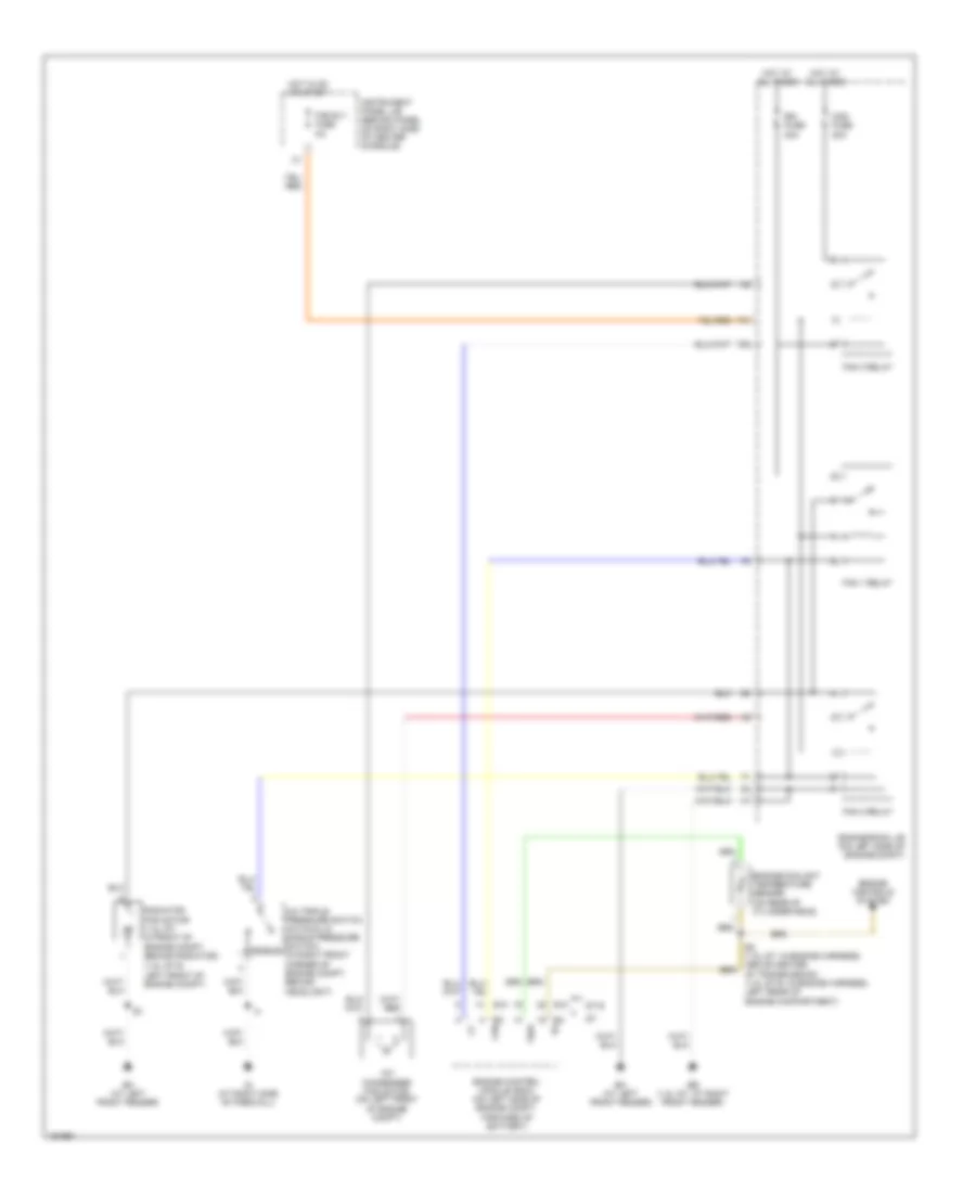
Cooling Fan Wiring Diagram for Toyota Celica GT 2004
List of elements for Cooling Fan Wiring Diagram for Toyota Celica GT 2004:
- (1.8l gt-s: left front of engine compt)
- A/c condenser fan motor (on left front of engine compt)
- A/c triple pressure switch (a/c dual & single pressure switch) single (in right front corner of engine compt, behind headlight)
- Cds fuse 30a
- E10
- E2 (1.8l gt: in engine harness, above center of transmission) (1.8l gt-s: in engine harness, left rear of engine compartment)
- E3 fan
- E4 e2
- Eb (1.8l gt: at right front fender)
- Em (at left front fender)
- Engine control module (ecm) (on left side of engine compt, forward of battery)
- Engine controls system
- Engine coolant temperature sensor (on rear of cylinder head)
- Engine room j/b (on left side of engine compt)
- F28
- F31
- Fan 1 relay
- Fan 2 relay
- Fan 3 relay
- Fan rly fuse 5a
- Gt-s
- Hot at all times
- Hot in on or start
- Ig (at right side of firewall)
- Instrument panel j/b (behind panel on right side of center console)
- Radiator fan motor (1.8l gt: in front of engine compt, behind radiator)
- Rdi fuse 30a
- Thw
 Čeština
 Dansk
Dansk Deutsch
 Ελληνικά
 English
 English
 Español
 Suomi
Suomi Français
 עברית
עברית Hrvatski
 Magyar
 Italiano
 日本語
日本語 한국어
한국어 Nederlands
 Polski
 Português
 Português
 Română
 Русский
 Slovenčina
 Slovenščina
 Svenska
 Türkçe
 中文 (中国)
 Français