CRUISE CONTROL
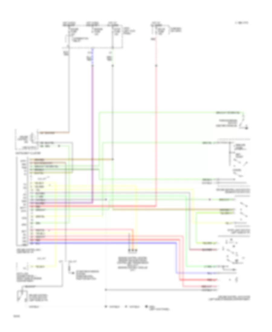
Cruise Control Wiring Diagram for Toyota T100 SR5 1994
List of elements for Cruise Control Wiring Diagram for Toyota T100 SR5 1994:
- 1995 vftc c
- 3.0l a/t
- Batt
- C13
- Cancel
- Ccs
- Cruise control actuator (left side of engine compartment)
- Cruise control clutch switch (left side of i/p)
- Cruise control ecu (center of i/p)
- Cruise control ind
- Cruise control main switch (combination switch)
- Data link connector no. 1 (right side of engine compartment)
- Ect
- Ecu-b fuse 15a
- Engine control system (engine and electronic controlled transmission ecu) (a/t) (engine control module) (m/t)
- Engine fuse 10a
- Fuse box (on j/b #1)
- G200 (left kick panel)
- Gauge fuse 10a
- Gnd
- Hot at all times
- Hot in run and start
- Idl
- Instrument cluster
- Integration relay
- J/b #1 (left kick panel)
- M/t
- N&c
- Parking brake switch (center console)
- Pkb
- Red
- Resume/ accel
- Set/ coast
- Spd
- Starting/charging system (park/neutral position switch)
- Stop fuse 15a
- Stop light switch (left side of i/p)
- Stp+
- Stp-
- Vr1
- Vr2
- Vr3
- Vss output
 Čeština
 Dansk
Dansk Deutsch
 Ελληνικά
 English
 English
 Español
 Suomi
Suomi Français
 עברית
עברית Hrvatski
 Magyar
 Italiano
 日本語
日本語 한국어
한국어 Nederlands
 Polski
 Português
 Português
 Română
 Русский
 Slovenčina
 Slovenščina
 Svenska
 Türkçe
 中文 (中国)
 Français