POWER DISTRIBUTION
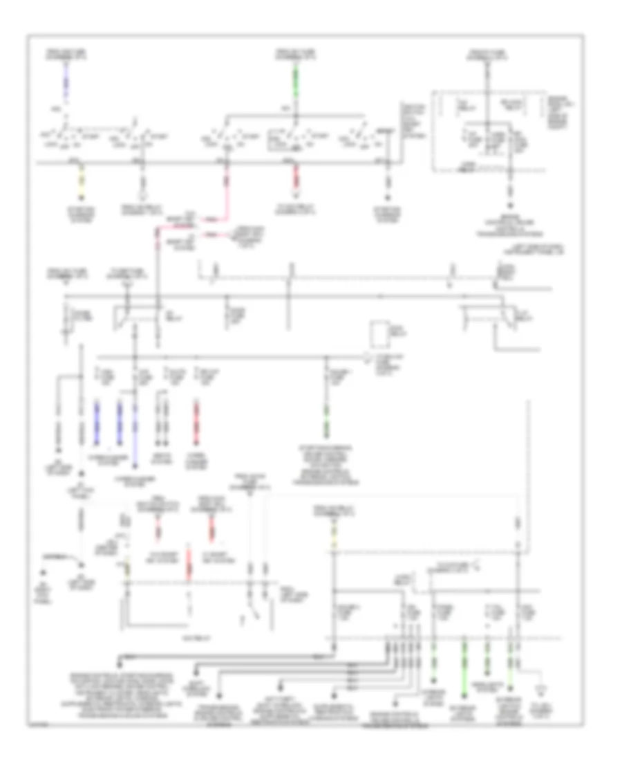
Power Distribution Wiring Diagram (1 of 3) for Toyota RAV4 Sport 2011
 https://portal-diagnostov.com/license.html
Automotive Electricians Portal FZCO
Automotive Electricians Portal FZCO
https://portal-diagnostov.com/license.html
https://portal-diagnostov.com/license.html
Automotive Electricians Portal FZCO
Automotive Electricians Portal FZCO
List of elements for Power Distribution Wiring Diagram (1 of 3) for Toyota RAV4 Sport 2011:
- (2.5l)
- (3.5l)
- (left side of engine compt) engine room r/b 1
- (right side of engine compt) engine room r/b 2
- (w/o trailer towing) (w/ trailer towing)
- 4wd fuse 7.5a
- A1 (2.5l: left rear of engine compt) (3.5l: left front of engine compt)
- A38
- A50
- A78
- A79
- Abs 1 fuse 50a
- Abs 2 fuse 30a
- Acc-b fuse 25a
- Accd
- Ae1
- Ae2
- Ae3
- Air conditioning & anti-theft systems
- Air conditioning & cooling fans systems
- Air conditioning system
- Alt fuse 120a 140a
- Alt-s fuse 7.5a
- Am1
- Am1 fuse 7.5a
- Am2
- Am2 fuse 30a
- Am2-2 fuse 7.5a
- Amp fuse 30a
- Anti-lock brakes system
- B18
- B19
- B26
- B43
- Battery
- Computer data lines system
- D fr door fuse 20a
- Dcc
- Defogger system
- Deicer fuse 20a
- Dome fuse 10a
- Door locks & interior lights systems
- E1 (left kick panel)
- E15
- E16
- E17
- E28
- Ecu-b fuse 10a
- Ecu-b2 fuse 7.5a
- Electronic power steering system
- Emps fuse 60a
- Engine controls, anti-lock brakes, cruise control, exterior lights, shift interlock & transmissions systems
- Engine controls, cruise control & transmissions systems
- Engine switch
- Etcs fuse 10a
- Exterior lights system
- Fan 1 fuse 50a cds fuse 30a
- Fan 2 fuse 50a rdi fuse 30a
- Fr fog fuse 15a
- From alt fuse (diagram 1 of 3)
- Generator
- H10
- Haz fuse 10a
- Head main fuse 50a
- Headlights system
- Htr fuse 50a
- Ig1d
- Ig2 fuse 15a
- Ig2 relay
- Ig2d
- Instrument panel j/b (left side of dash)
- J/b 3 (left side of dash)
- Main body ecu (w/ smart key system) (left side of dash)
- Main fuse 80a
- Obd fuse 7.5a
- P/i fuse 50a
- P/seat fuse 30a
- Pnk
- Power tops system
- Power windows system
- Q13
- Rad 1 fuse 20a
- Red
- S/roof fuse 25a
- Seats system
- Shift interlock system
- Sound systems
- Ssw1
- Ssw2
- Starting/ charging system
- Stop fuse 10a
- Str lock fuse 20a
- To ac inv fuse (diagram 3 of 3)
- To acc relay (diagram 2 of 3)
- To gauge 2 fuse (diagram 2 of 3)
- To horn fuse (diagram 2 of 3)
- To ignition switch (diagram 2 of 3)
- To instrument panel j/b (diagram 2 of 3)
- To main switch (diagram 3 of 3)
- To noise filter (diagram 2 of 3)
- To s/roof fuse (diagram 1 of 3)
- Towing fuse 30a
- Transmissions system
- W/ smart key system
- W/o smart key system
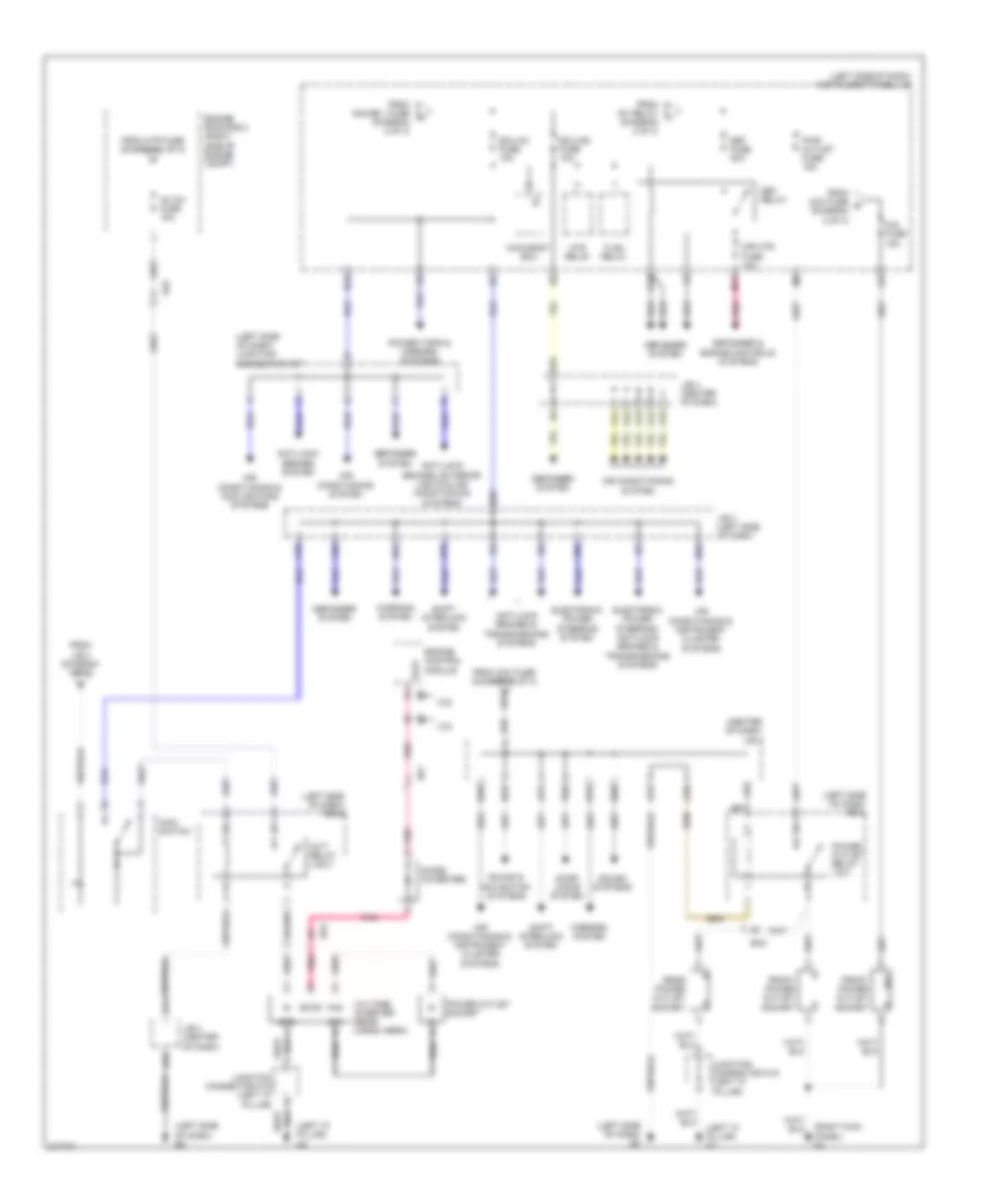
Power Distribution Wiring Diagram (2 of 3) for Toyota RAV4 Sport 2011
List of elements for Power Distribution Wiring Diagram (2 of 3) for Toyota RAV4 Sport 2011:
- (left side of dash) instrument panel j/b
- A/f fuse 20a
- A/f relay
- A10
- A12
- A25
- A70
- Acc
- Acc fuse 7.5a
- Acc relay
- Altb
- Am1
- Am2
- B15
- B27
- B29
- B36
- C/opn relay
- C15
- Door fuse 25a
- E1 (left kick panel)
- E10
- E12
- E16
- E17
- E2 (left side of dash)
- E21
- E3 (left side of dash)
- E4 (right kick panel)
- Efi main fuse 20a
- Efi main relay
- Engine controls, cruise control & transmissions systems
- Engine room j/b 1 (left side of engine compt)
- Exterior lights & engine controls systems
- Exterior lights systems
- From acc-b fuse (diagram 1 of 3)
- From am1 fuse (diagram 1 of 3)
- From am2 fuse (diagram 1 of 3)
- From ig2 relay (diagram 1 of 3)
- From ignition switch (diagram 2 of 3)
- From main body ecu (diagram 1 of 3)
- From p/i fuse (diagram 1 of 3)
- Gauge 1 fuse 10a
- Gauge 2 fuse 7.5a
- Gnd1
- Headlights system
- Horn fuse 10a
- Horn relay
- Ig1
- Ig1 relay
- Ig2
- Ign fuse 7.5a
- Ignition switch (w/o smart key system)
- Interior lights system
- J/b 4 (center of dash)
- Lock off
- Main body ecu acc
- Noise filter
- Panel fuse 7.5a
- Pnk
- Pwr relay
- Q10
- R/b 5 (left side of dash)
- Red
- Rr wip fuse 15a
- S-htr fuse 15a
- Seats system
- Shift interlock system
- St1
- St2
- Start
- Starting/ charging system
- Starting/charging, cruise control, sound, mirrors, navigation, engine controls, exterior lights & transmissions systems
- T-lp relay
- Tail fuse 10a
- To acc relay (diagram 2 of 3)
- To cig fuse (diagram 3 of 3)
- To def fuse (diagram 3 of 3)
- To ecu-ig1 fuse (diagram 3 of 3)
- To j/b 4 (diagram 3 of 3)
- Transmissions, engine controls & cruise control systems
- Trly
- W/ smart key system
- W/o smart key system
- Wip fuse 25a
- Wiper/ washer system
- Wiper/washer system
- Wsh fuse 15a
Power Distribution Wiring Diagram (3 of 3) for Toyota RAV4 Sport 2011
List of elements for Power Distribution Wiring Diagram (3 of 3) for Toyota RAV4 Sport 2011:
- (center of dash) j/b 4
- (left "c" pillar) k2
- (left side of dash) e3
- (left side of dash) instrument panel j/b
- (left side of dash) junction connector a37
- (left side of dash) r/b 5
- (left side of dash) r/b 6
- (right kick panel) e4
- 2.5l
- 3.5l
- A10
- A11
- A33
- A41
- A42
- A43
- A44
- A45
- A69
- A70
- A75
- A78
- A82
- Ac inv fuse 15a
- Ac1
- Ac2
- Acc
- Ae1
- Ae2
- Air conditioning & cooling fans systems
- Air conditioning & instrument cluster systems
- Air conditioning system
- Anti-lock brakes & transmissions systems
- Anti-lock brakes system
- Anti-lock brakes, exterior lights & air conditioning systems
- B15
- B24
- B38
- B39
- B40
- B50
- B53
- B68
- B69
- Cig fuse 15a
- Def fuse 30a
- Def relay
- Defogger & engine controls systems
- Defogger system
- Diode (inverter)
- Door locks system
- Ecu-ig1 fuse 10a
- Ecu-ig2 fuse 10a
- Ek2
- Electronic power steering system
- Electronic power steering, anti-lock brakes & transmissions systems
- Els1
- Engine control module
- Engine room r/b 2 (right side of engine compt)
- Excd
- Flsh relay
- From acc fuse (diagram 2 of 3)
- From acc fuse o (diagram 2 of 3)
- From gauge 1 fuse (diagram 2 of 3)
- From htr fuse (diagram 1 of 3)
- From ig1 relay (diagram 2 of 3)
- From j/b 3 (diagram 1 of 3)
- Front power outlet socket
- Gnd
- Htr relay
- Invt relay (120v)
- J/b 3 (left side of dash)
- J/b 4 (center of dash)
- Junction connector k19 (left "c" pillar)
- M11
- Main body ecu
- Main switch
- Mir htr fuse 10a
- Mirrors system
- Pnk
- Power outlet relay (12v)
- Power outlet socket
- Power tops & mirrors systems
- Pwr outlet fuse 15a
- Q12
- Rear power outlet socket
- Shift interlock system
- Sound & navigation systems
- Sound systems
- Voltage inverter (rear cargo area)
- Warning system

 Čeština
 Dansk
Dansk Deutsch
 Ελληνικά
 English
 English
 Español
 Suomi
Suomi Français
 עברית
עברית Hrvatski
 Magyar
 Italiano
 日本語
日本語 한국어
한국어 Nederlands
 Polski
 Português
 Português
 Română
 Русский
 Slovenčina
 Slovenščina
 Svenska
 Türkçe
 中文 (中国)