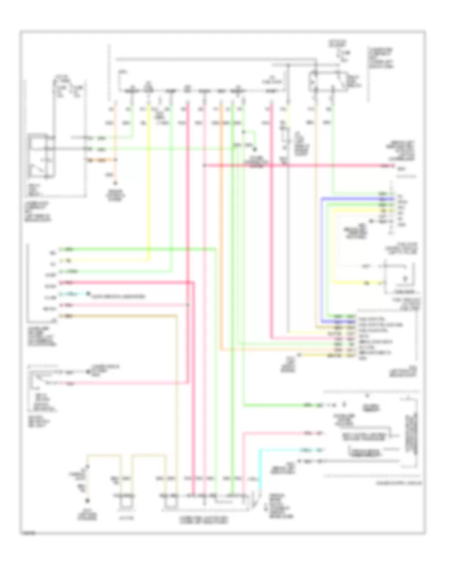
AIR CONDITIONING
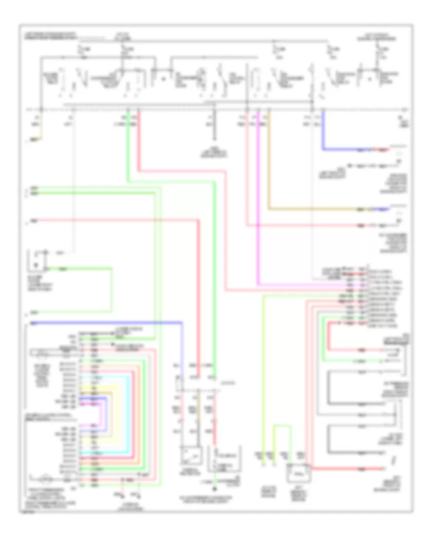
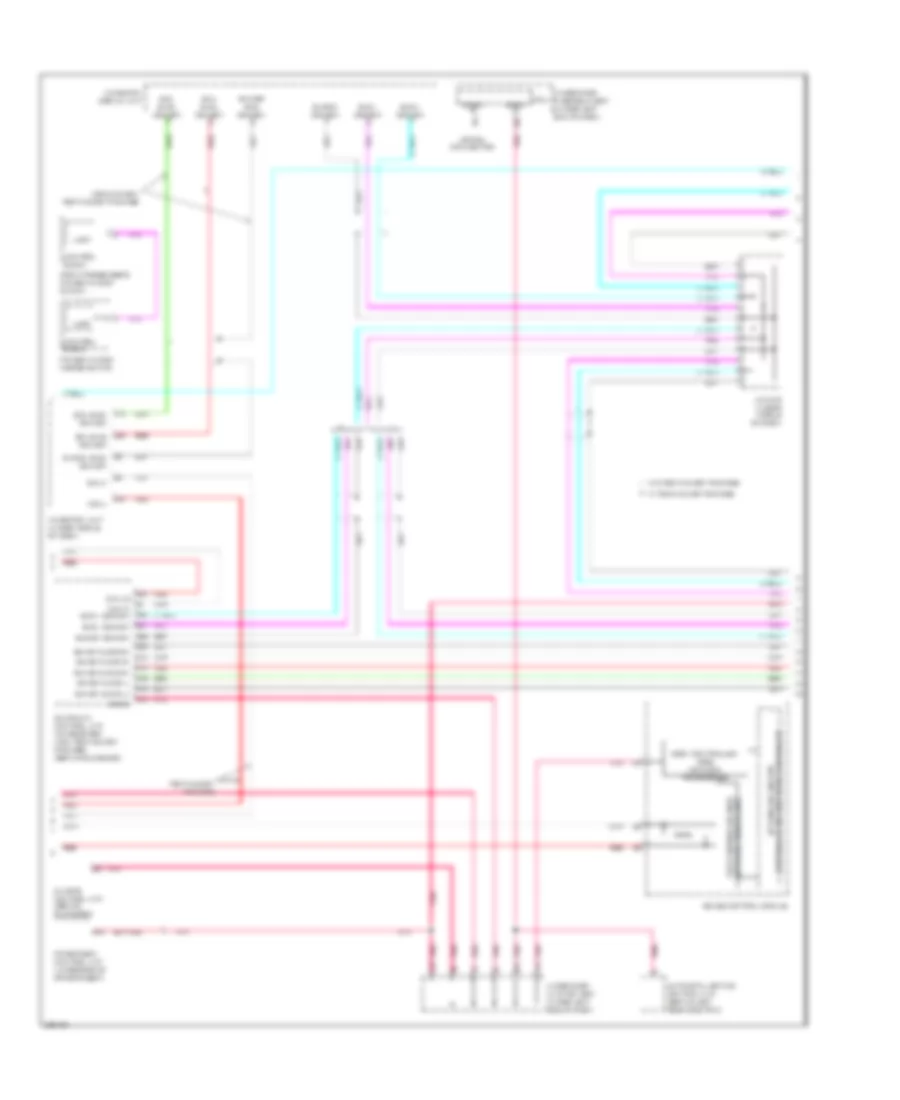
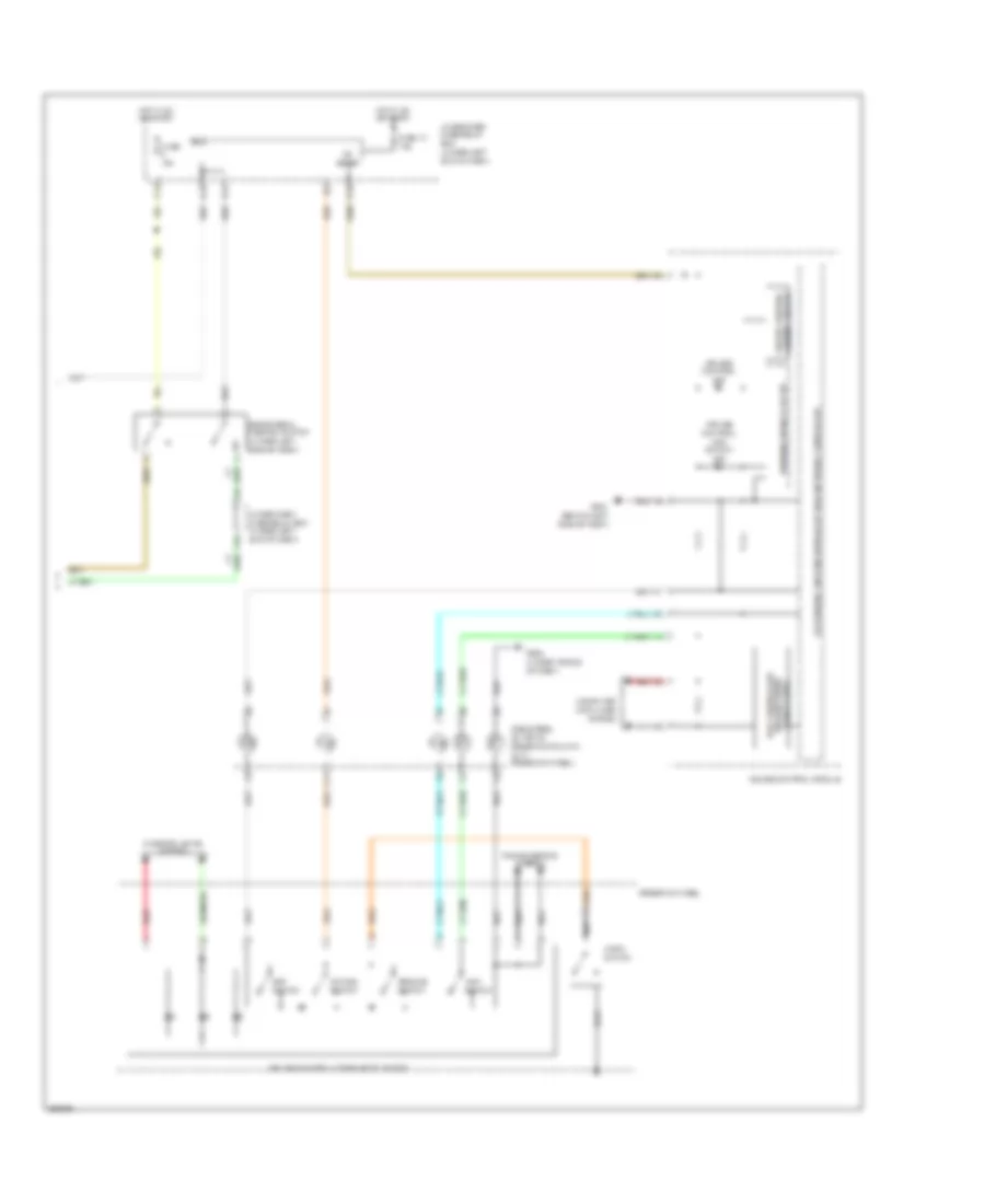
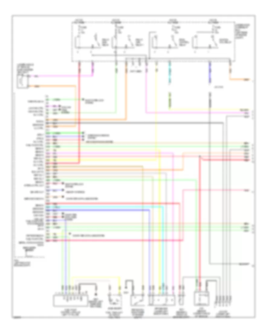
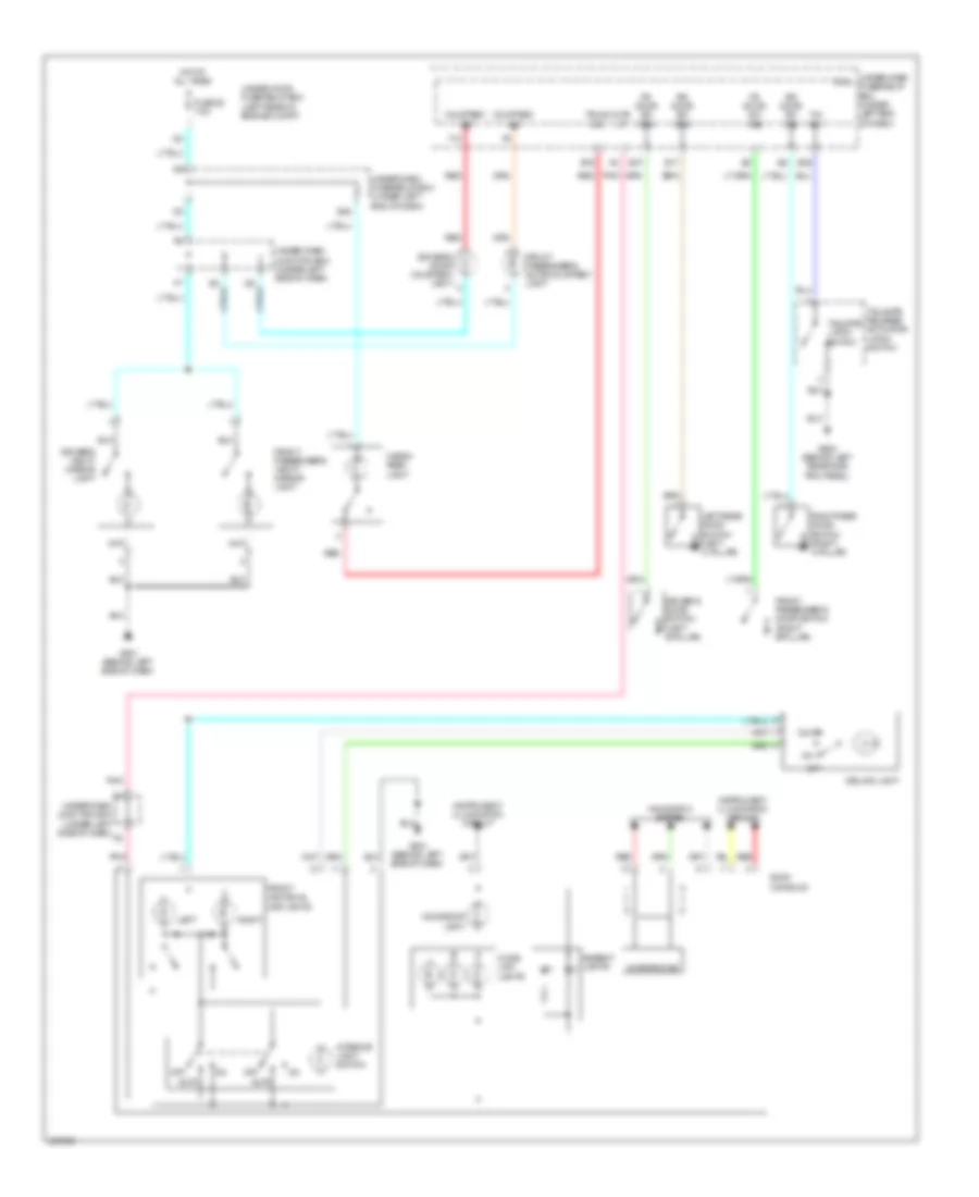
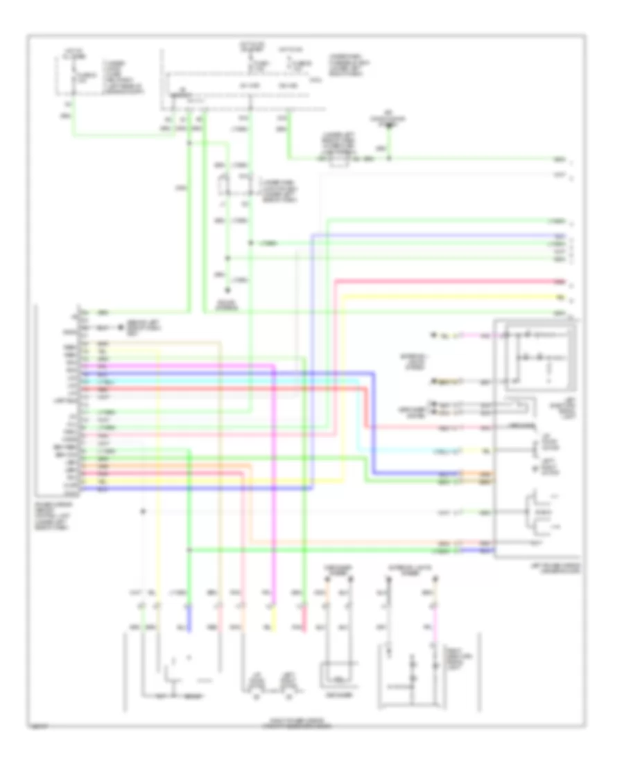
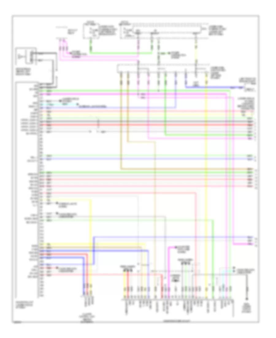
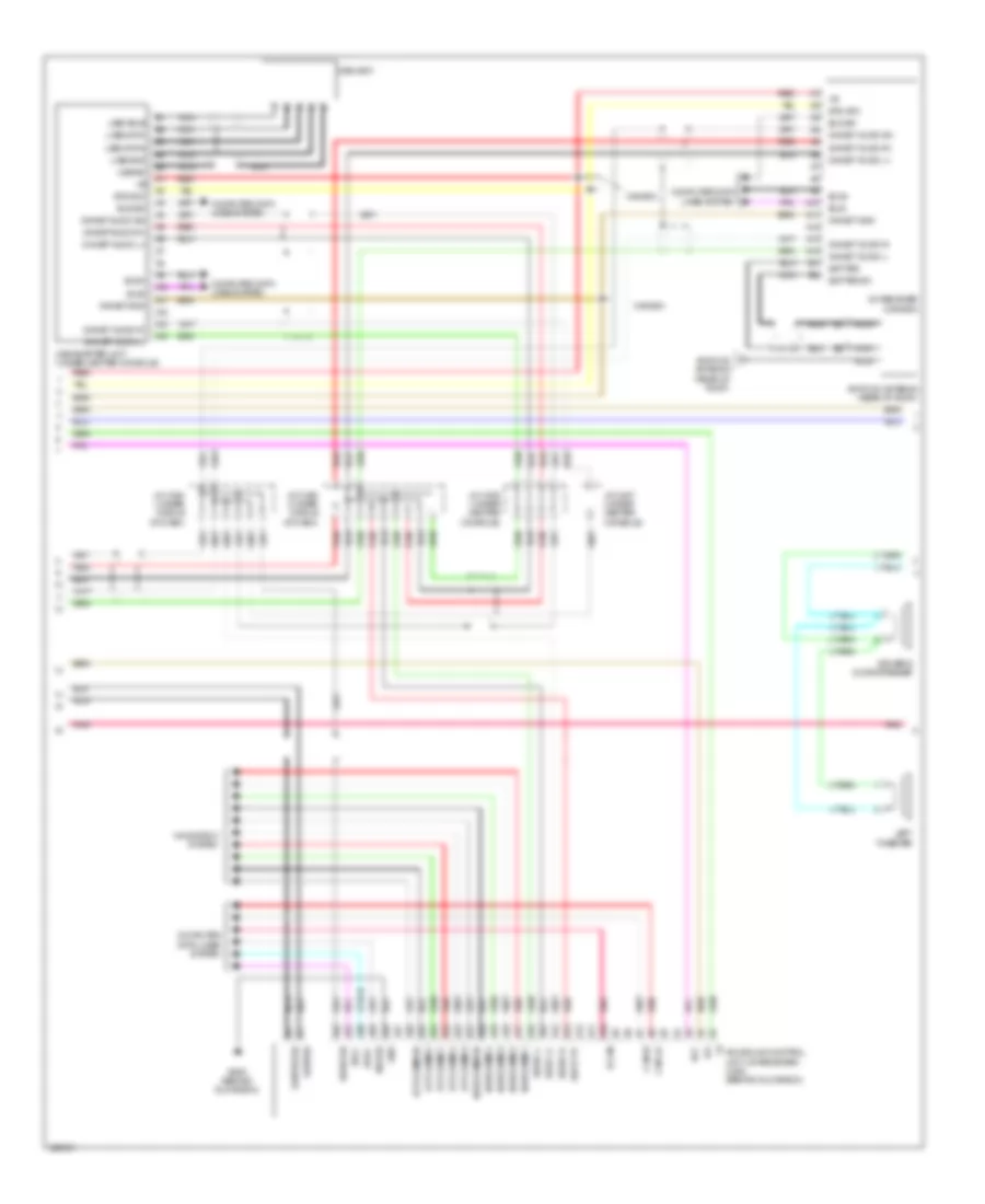
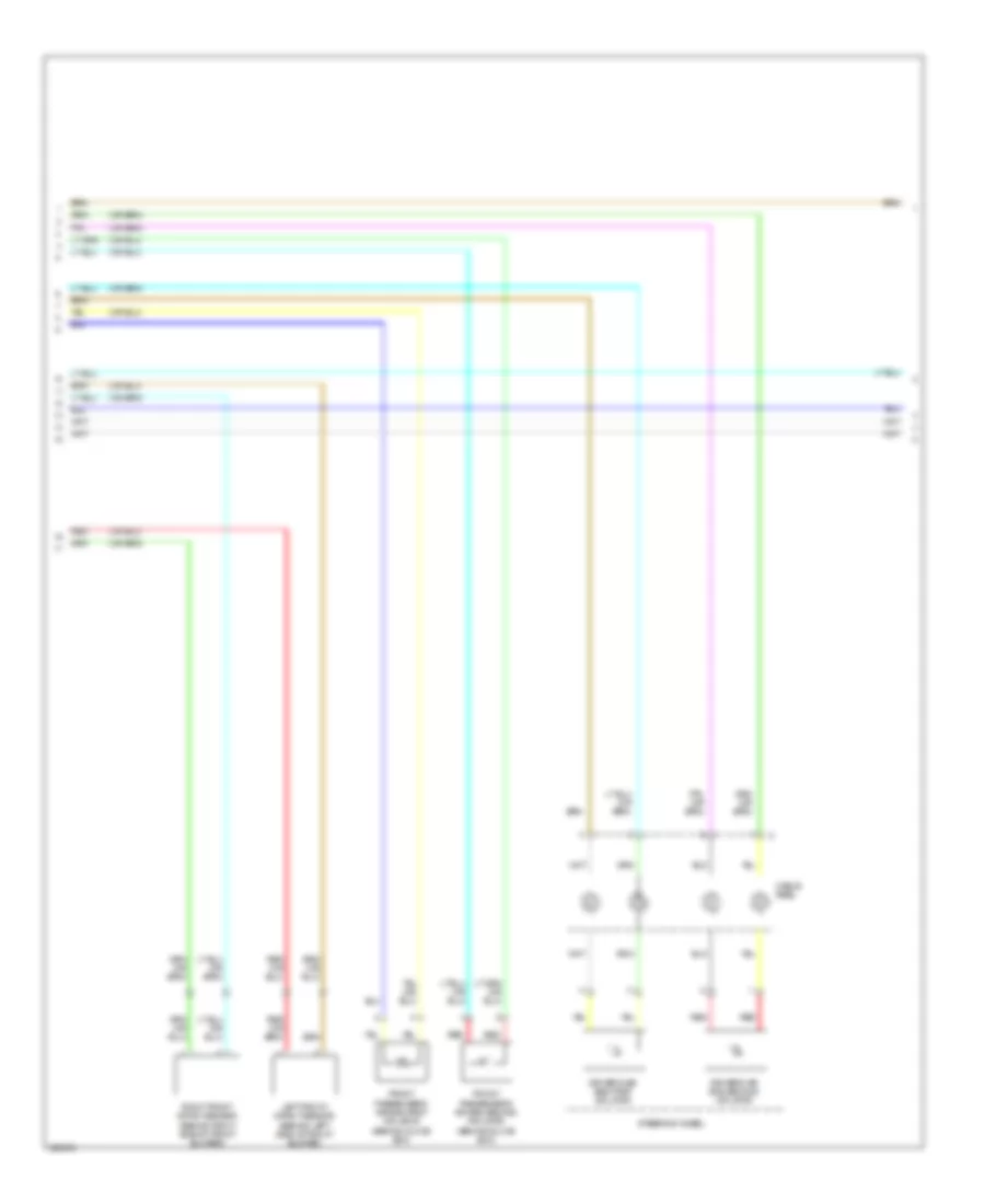
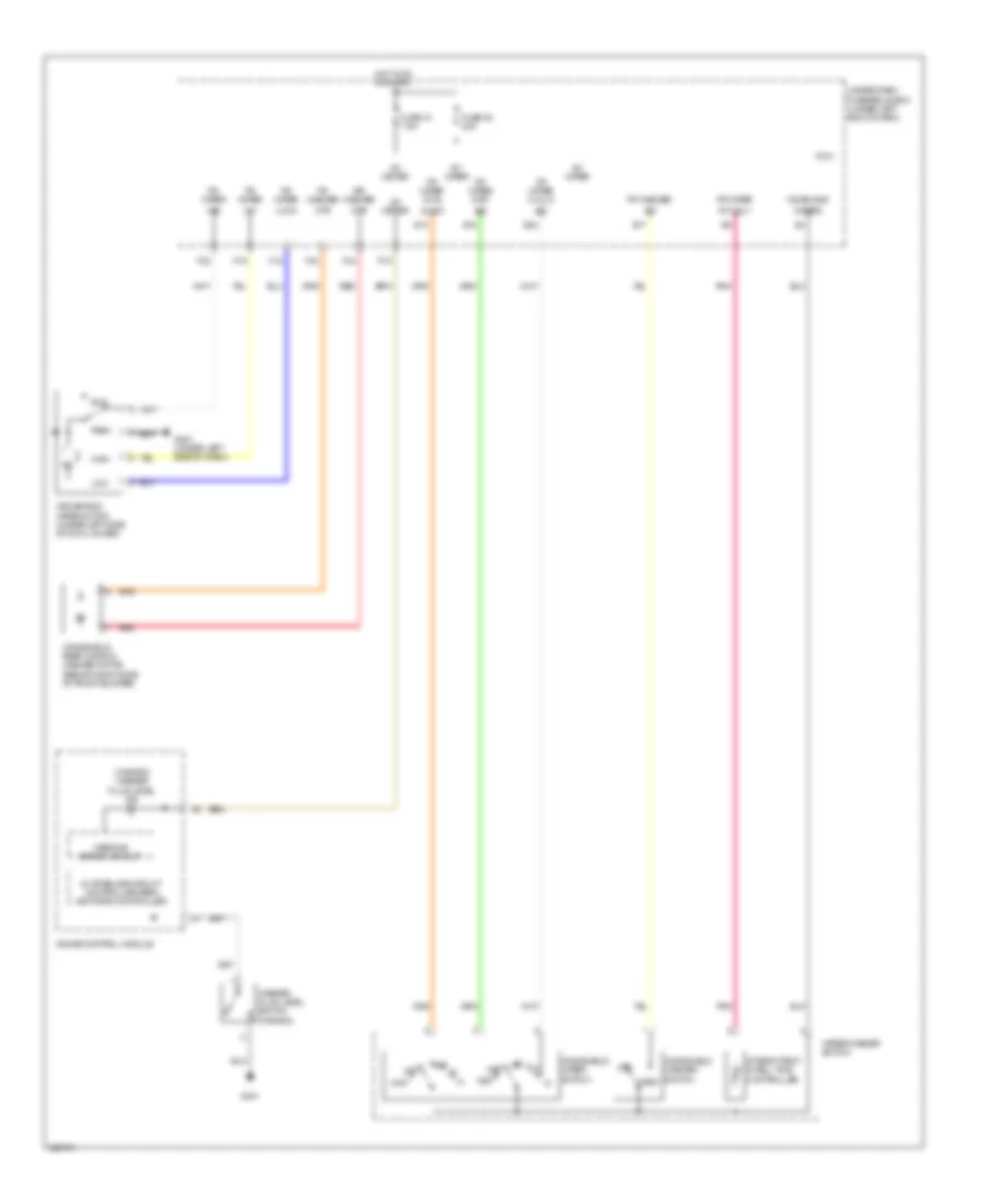
Automatic A/C Wiring Diagram (1 of 2) for Acura RDX 2010
 https://portal-diagnostov.com/license.html
Automotive Electricians Portal FZCO
Automotive Electricians Portal FZCO
https://portal-diagnostov.com/license.html
https://portal-diagnostov.com/license.html
Automotive Electricians Portal FZCO
Automotive Electricians Portal FZCO
List of elements for Automatic A/C Wiring Diagram (1 of 2) for Acura RDX 2010:
- (under right side of dash) g571
- A10
- A11
- A12
- A13
- A14
- A15
- A16
- A17
- A18
- A19
- A20
- A21
- A22
- A23
- A24
- Acs
- Amd-p
- Amd-p-as
- Amd-p-dr
- Audio-si
- Automatic lighting sensor/sunlight sensor (middle of dash)
- B-can
- B10
- B11
- B12
- B13
- B14
- B15
- B16
- Blower power transistor (under right side of dash, near blower motor)
- Blw-g
- Blw-v
- Bus-data
- Climate control unit (behind glove box)
- Computer data lines system
- Defogger system
- Driver's air mix control motor (under left side of dash)
- Evaporator temperature sensor connector (behind glove box)
- F26
- Front passenger's air mix control motor (under right side of dash)
- Frs
- Fuse 10a
- G12
- Gnd
- Hot in on
- Ig2
- Ig2 hac
- In-car temperature sensor (left side of dash)
- J22
- M-cool
- M-cool-as
- M-cool-dr
- M-def
- M-hot
- M-hot-as
- M-hot-dr
- M-vent
- Micu
- Mode 1
- Mode 2
- Mode 3
- Mode 4
- Mode control motor (behind glove box, on hvac assembly)
- Navi-clk
- Navi-si
- Navi-so
- Navigation system
- Outside air temperature sensor (behind middle of front bumper)
- Pnk
- Q16
- Rec
- Recirculation control motor (behind glove box, on hvac assembly)
- Red
- Rr def relay
- S-com
- S5v
- Sens-com
- Sound systems
- Sunlight sensor
- Tam
- Teve
- Tsun
- Under-dash fuse/relay box (under left end of dash)
- Under-dash junction box (under left side of dash)
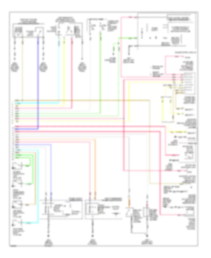
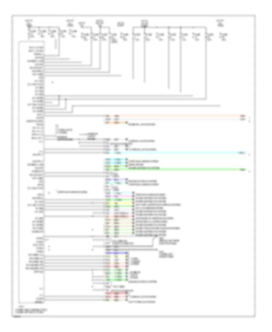
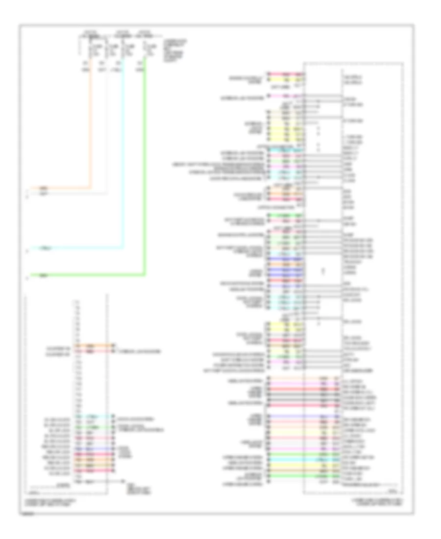
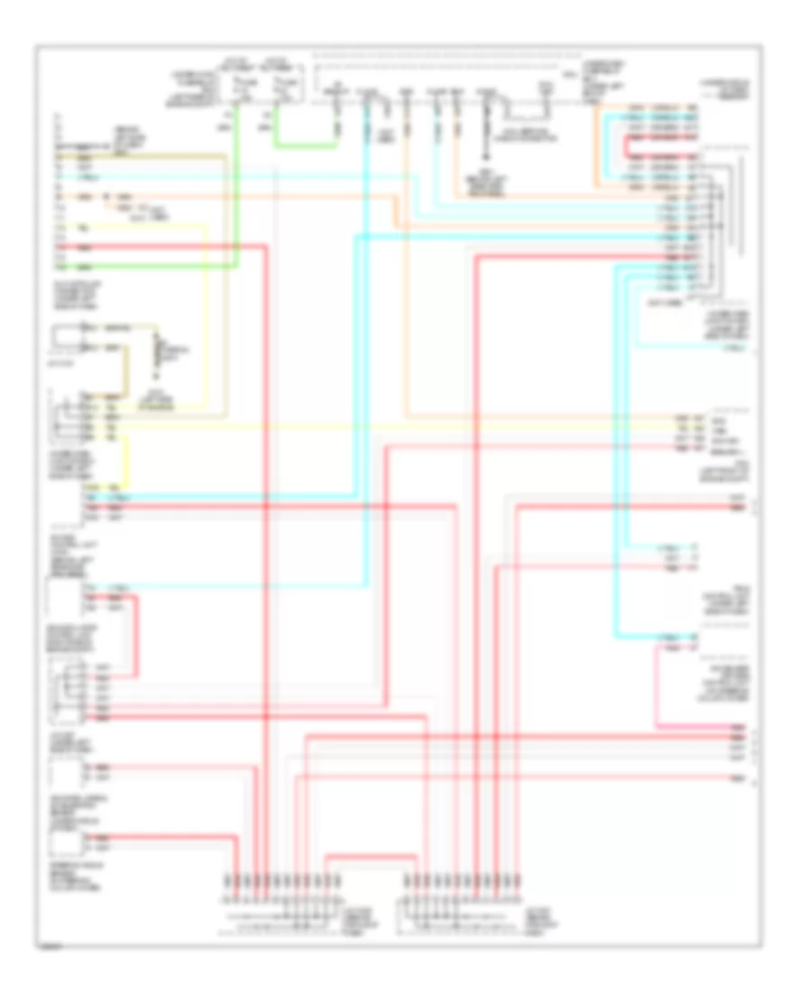
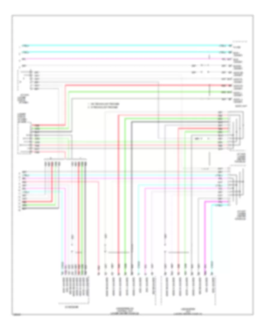
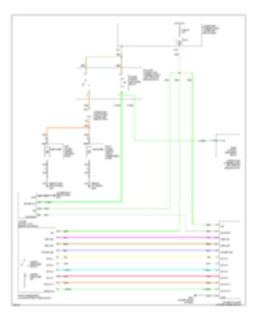
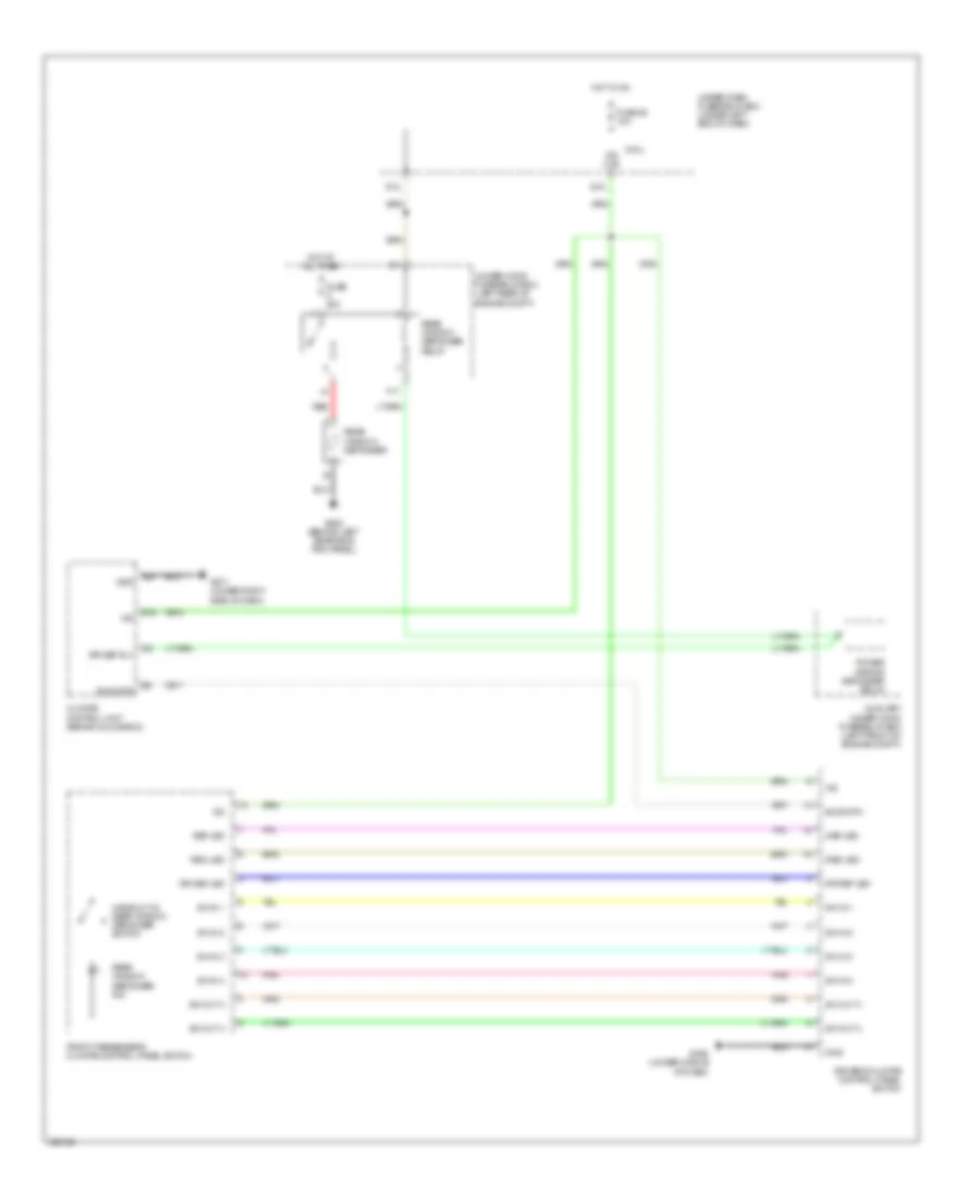
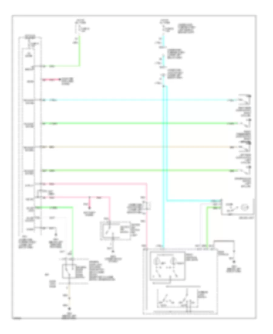
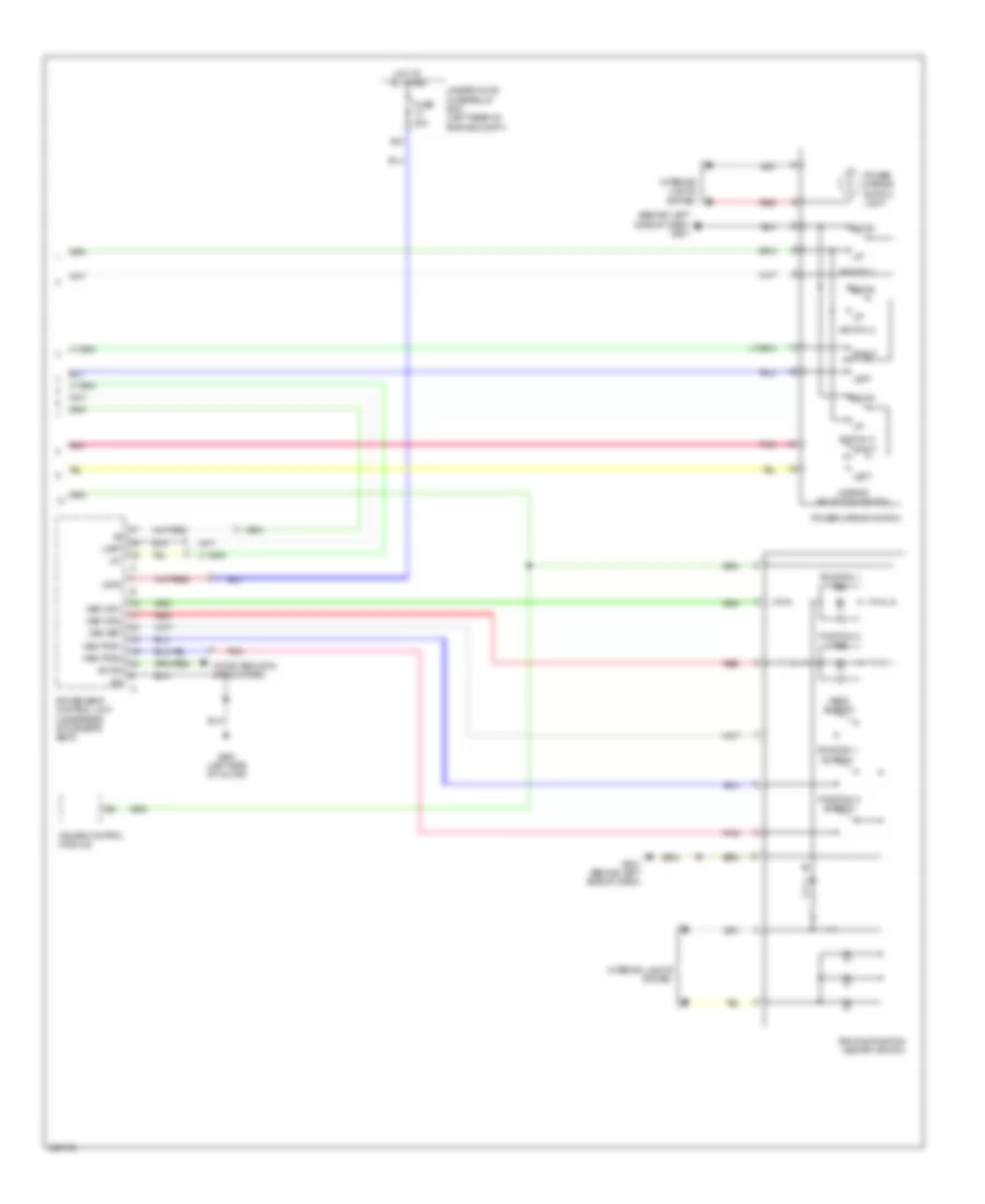
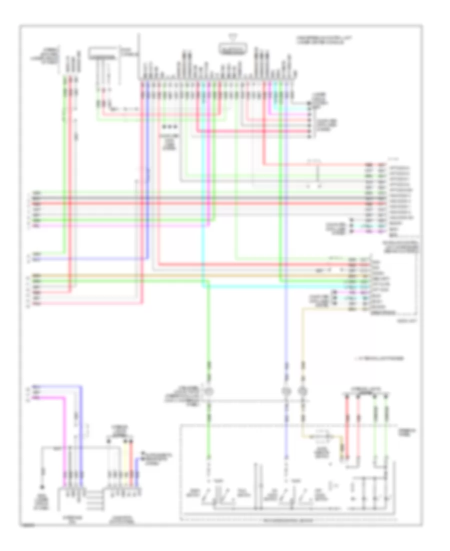
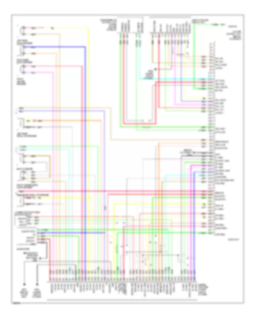
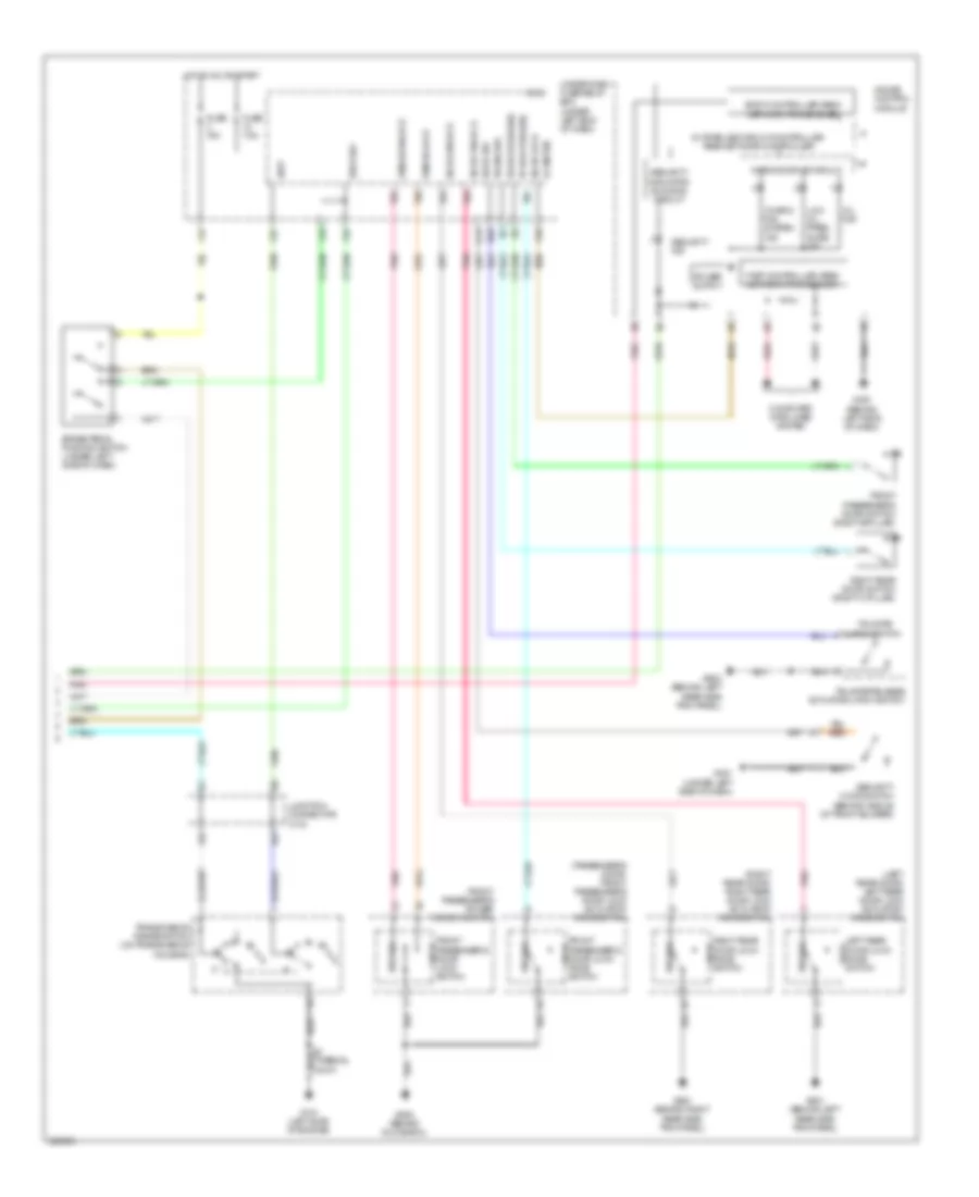
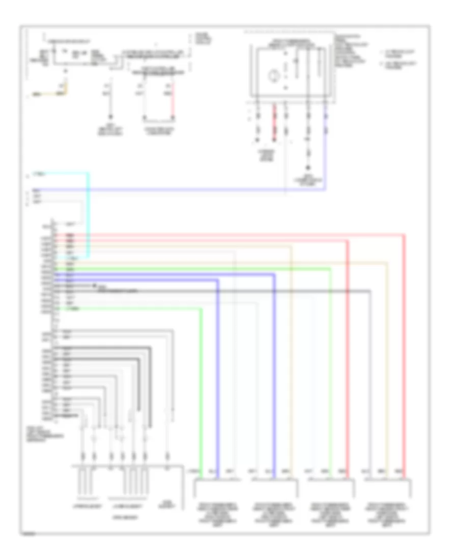
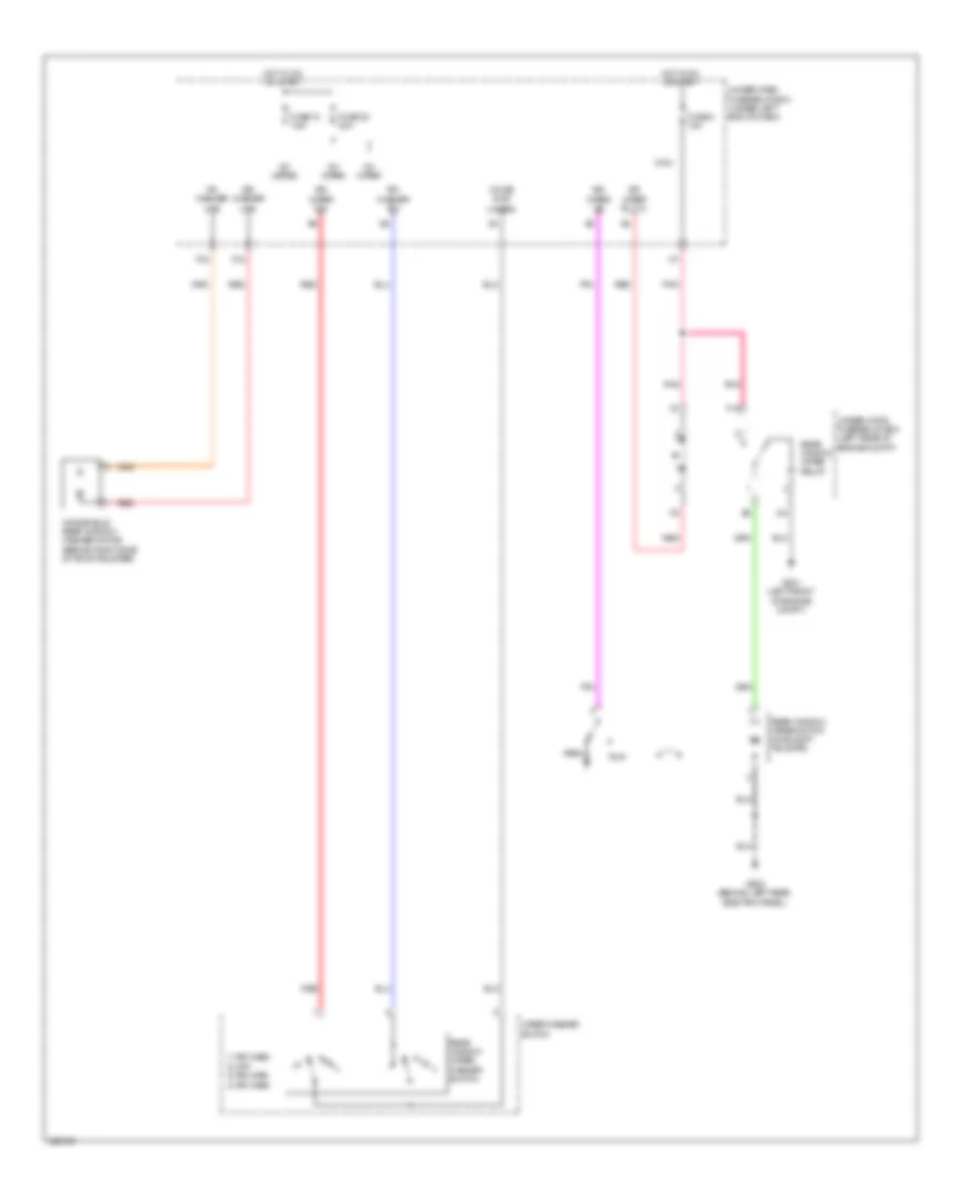
Automatic A/C Wiring Diagram (2 of 2) for Acura RDX 2010
List of elements for Automatic A/C Wiring Diagram (2 of 2) for Acura RDX 2010:
- (left rear of engine compt) under-hood fuse/relay box
- (not used)
- (under middle of dash) g502
- A/c compressor clutch
- A/c compressor clutch relay
- A/c compressor connector (front of engine compt)
- A/c condenser fan diode
- A/c condenser fan motor connector (front of engine compt)
- A/c condenser fan relay
- A/c pressure sensor (right side of engine compt)
- A14
- A16
- A18
- A19
- A33
- A36
- A37
- B19
- B23
- B33
- Blower motor (under right side of dash)
- Blower motor relay
- Bus-data
- Computer data lines system
- Def-led
- Driver's climate control panel switch
- Driver's climate control panel switch lights
- Ect sensor 1 (rear of engine)
- Ect sensor 2 (front of engine compt)
- F11
- F12
- F14
- F20
- Fan control relay
- Front passenger's climate control panel switch
- Front passenger's climate control panel switch lights
- Fuse 30a
- Fuse 40a
- Fuse 7.5a
- G201 (left front of engine compt)
- G202 (left rear of engine compt)
- Gnd
- Hi fan ctrl (fanh)
- Hot at all times
- Hot w/ pgm-fi sub-relay energized
- Ig2
- Ill+
- Interior lights system
- J/c c103
- J/c c105 (rear of engine)
- J/c c207 (under left side of dash)
- Lo fan ctrl (fanl)
- Pcm (left front of engine compt)
- Pnk
- Radiator fan diode
- Radiator fan motor connector (front of engine compt)
- Radiator fan relay
- Rec-led
- Red
- Ref volt (vcc6)
- Relay ctrl (acc)
- Rr-def-led
- Sens gnd (sg2)
- Sens gnd (sg6)
- Sens in (acpd)
- Sens in (ect1)
- Sens in (ect2)
- Sig hi (canh)
- Sig lo (canl)
- Solenoid
- Sw-in-1
- Sw-in-2
- Sw-in-3
- Sw-in-4
- Sw-out-3
- Sw-out-4
- Thermal fuse
- Thermal protector
ANTI-LOCK BRAKES
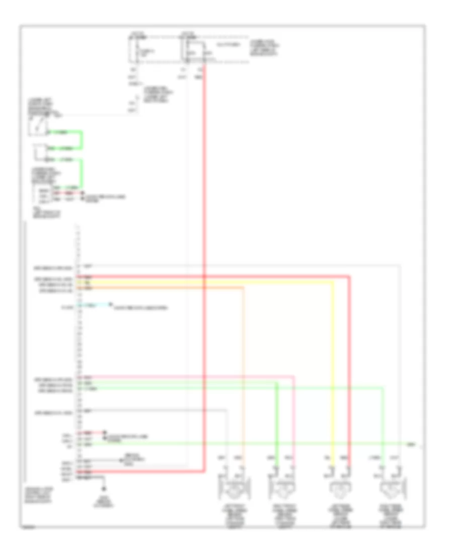
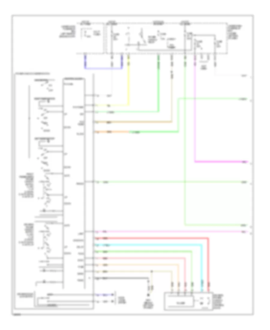
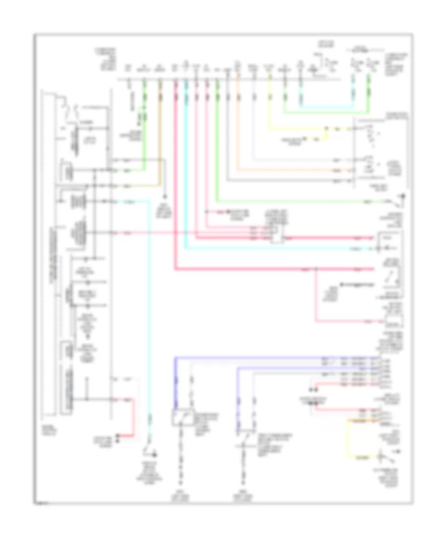
Anti-lock Brakes Wiring Diagram (1 of 2) for Acura RDX 2010
List of elements for Anti-lock Brakes Wiring Diagram (1 of 2) for Acura RDX 2010:
- (behind glove box) g402
- (under left side of dash) brake pedal position switch
- +b mot
- +b sol
- 20a
- 40a
- A36
- A37
- A40
- Bksw
- Can h
- Can l
- Computer data lines system
- F25
- F30
- F31
- Fuse 12 15a
- G16
- G402 (behind glove box)
- Gnd 1
- Gnd 2
- Hot at all times
- Ig1
- K-line
- Left front wheel speed sensor (left side of engine compt)
- Left rear wheel speed sensor (under left rear of vehicle)
- Multi-fuse 3
- Pcm (left front of engine compt)
- Pnk
- Red
- Right front wheel speed sensor (right side of engine compt)
- Right rear wheel speed sensor (under right rear of vehicle)
- Spd sens in (fl+b)
- Spd sens in (fl-gnd)
- Spd sens in (fr+b)
- Spd sens in (fr-gnd)
- Spd sens in (rl+b)
- Spd sens in (rl-gnd)
- Spd sens in (rr+b)
- Spd sens in (rr-gnd)
- Under-dash fuse/relay box (under left end of dash)
- Under-hood fuse/relay box (left rear of engine compt)
- Vsa modulator control unit (right side of engine compt)
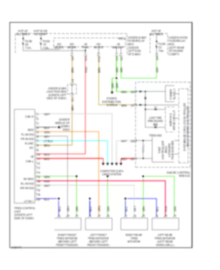
Anti-lock Brakes Wiring Diagram (2 of 2) for Acura RDX 2010
List of elements for Anti-lock Brakes Wiring Diagram (2 of 2) for Acura RDX 2010:
- (amber) brake system ind
- (red) brake system ind
- (under middle of dash) g503
- +b back up
- 5v stabilize circuit/ controller area network controller
- Abs ind
- Active circuit
- Brake fluid check circuit
- Brake fluid level switch (on brake master cylinder reservoir)
- Can h
- Can l
- Computer data lines system
- F16
- Fast controller area network transceiver
- Fuse 10 7.5a
- Fuse 4 7.5a
- G451 (under left side of dash)
- G501 (behind left side of dash)
- G502 (under middle of dash)
- Gauge control module
- Gnd
- Hot in on or start
- Ig1 abs
- Ig1 meter
- Interior lights system
- Micu
- P10
- Parking brake check circuit
- Parking brake switch (at base of parking brake lever)
- Pnk
- Power distribution system
- R20
- Red
- Steering angle sensor (in steering column cover)
- Under-dash fuse/relay box (under left end of dash)
- Vsa activation ind
- Vsa off switch
- Vsa system ind
- Warning drive circuit
- Yaw rate-lateral acceleration sensor (under middle of dash)
ANTI-THEFT
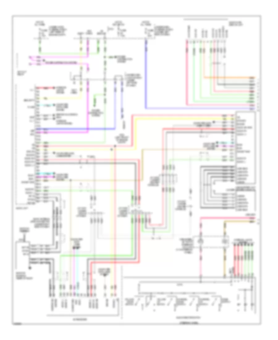
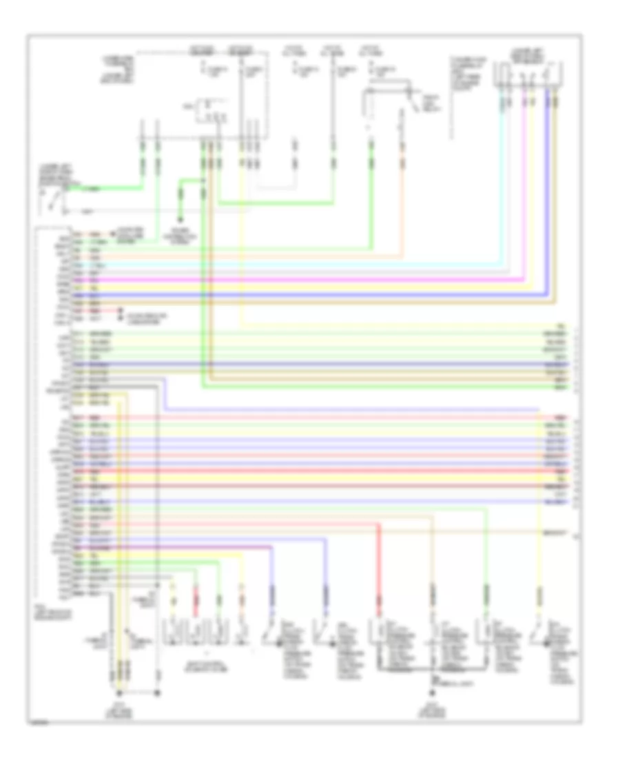
Forced Entry Wiring Diagram (1 of 2) for Acura RDX 2010
List of elements for Forced Entry Wiring Diagram (1 of 2) for Acura RDX 2010:
- (behind glove box) g505
- (behind left side of dash) g501
- (behind right rear side trim panel) g651
- (not used)
- (on transmission housing) transmission range switch
- (thermal joint) s2
- +b backup
- A23
- Anti-theft system
- Atpp
- B-can
- Door lock actuator
- Door lock knob
- Door lock relay
- Driver's door key cylinder switch
- Driver's door lock actuator/knob switch (driver's door)
- Driver's door lock knob switch
- Driver's door unlock relay
- E13
- E14
- E17
- E19
- E20
- E21
- E31
- E33
- E36
- E37
- Exterior lights system
- F20
- F23
- F27
- Fr dr sw (as)
- Fr dr sw (dr)
- Front passenger's door lock actuator/knob switch (passenger's door)
- Front passenger's door lock knob switch
- Fuse 15a
- Fuse 20a
- Fuse 30a
- Fuse 7.5a
- G101 (left side of engine)
- G13
- G16
- G17
- G451 (under left side of dash)
- G601 (behind left rear side trim panel)
- Headlights system
- Hood sw
- Horn relay
- Horns system
- Hot at all times
- Hot in on or start
- Ig1 meter
- J/c c103
- Kc dr lock
- Kc dr unlock
- Key
- Key sw
- Keyless buzzer
- Lock
- Low beam head- light relay
- M10
- Micu
- N13
- P-gnd
- Passenger's door unlock relay
- Pnk
- R13
- R16
- Red
- Rem as lock
- Rem as unlock
- Rem dr lock
- Rem dr unlock
- Right rear door lock actuator/knob switch (right rear door)
- Right rear door lock knob switch
- Rr dr sw (as)
- Rr dr sw (dr)
- S-gnd
- S-gnd2
- Scty1
- Sil as unlock
- Sil dr lock
- Sil dr unlock
- Sil ra unlock
- Sil rd unlock
- T/g handle sw
- T/g sw
- T22
- T23
- T24
- T25
- T26
- T27
- T28
- T29
- T30
- T31
- T32
- T34
- Tailgate unlock relay
- Taillight relay
- Under-dash fuse/relay box (under left end of dash)
- Unlock
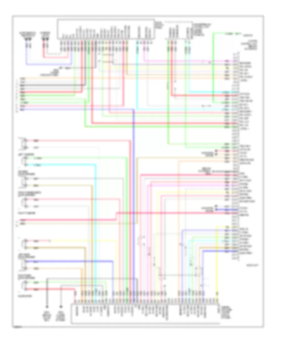
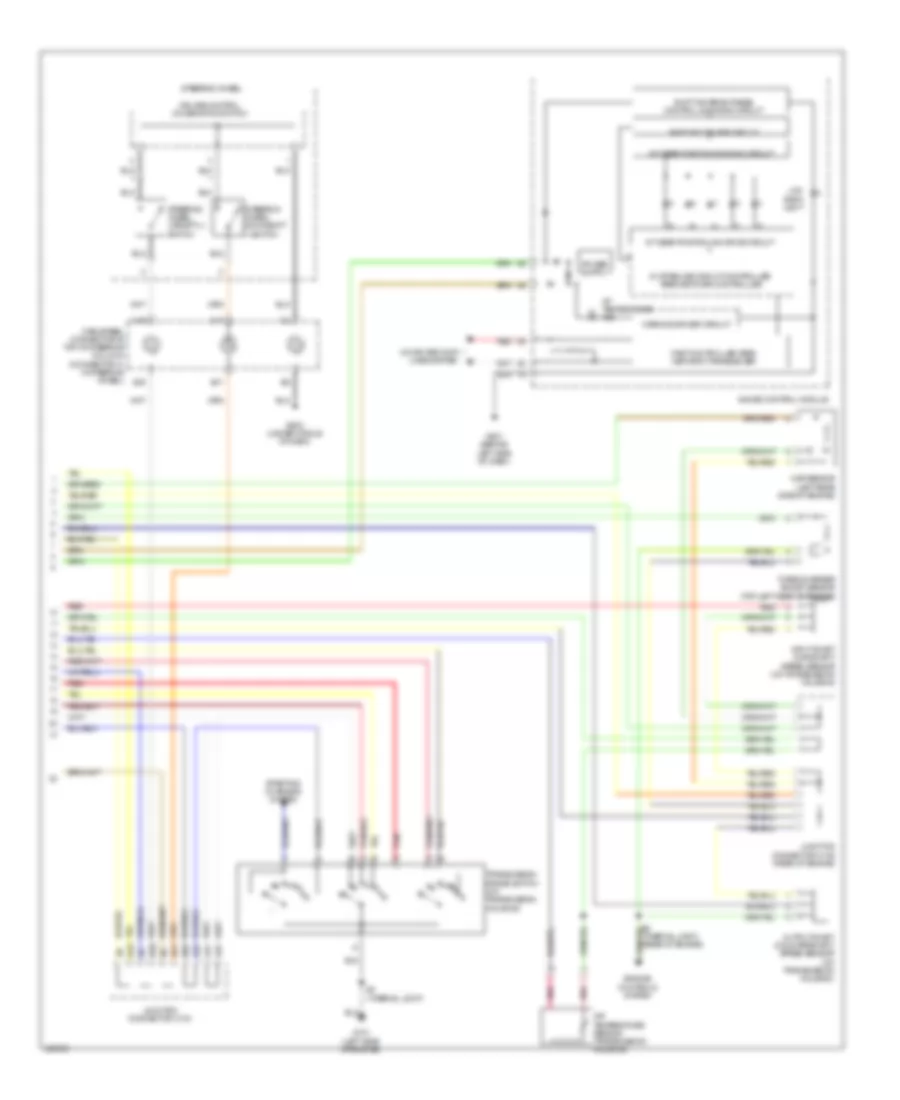
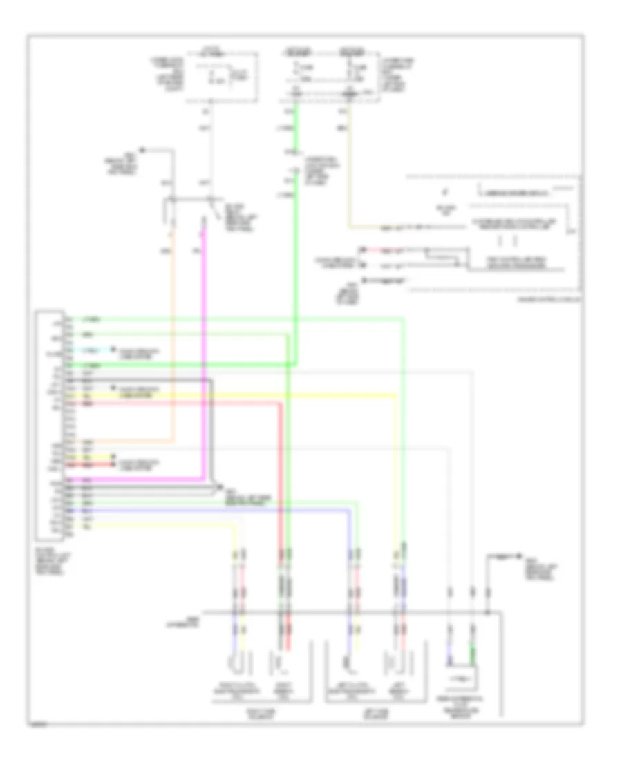
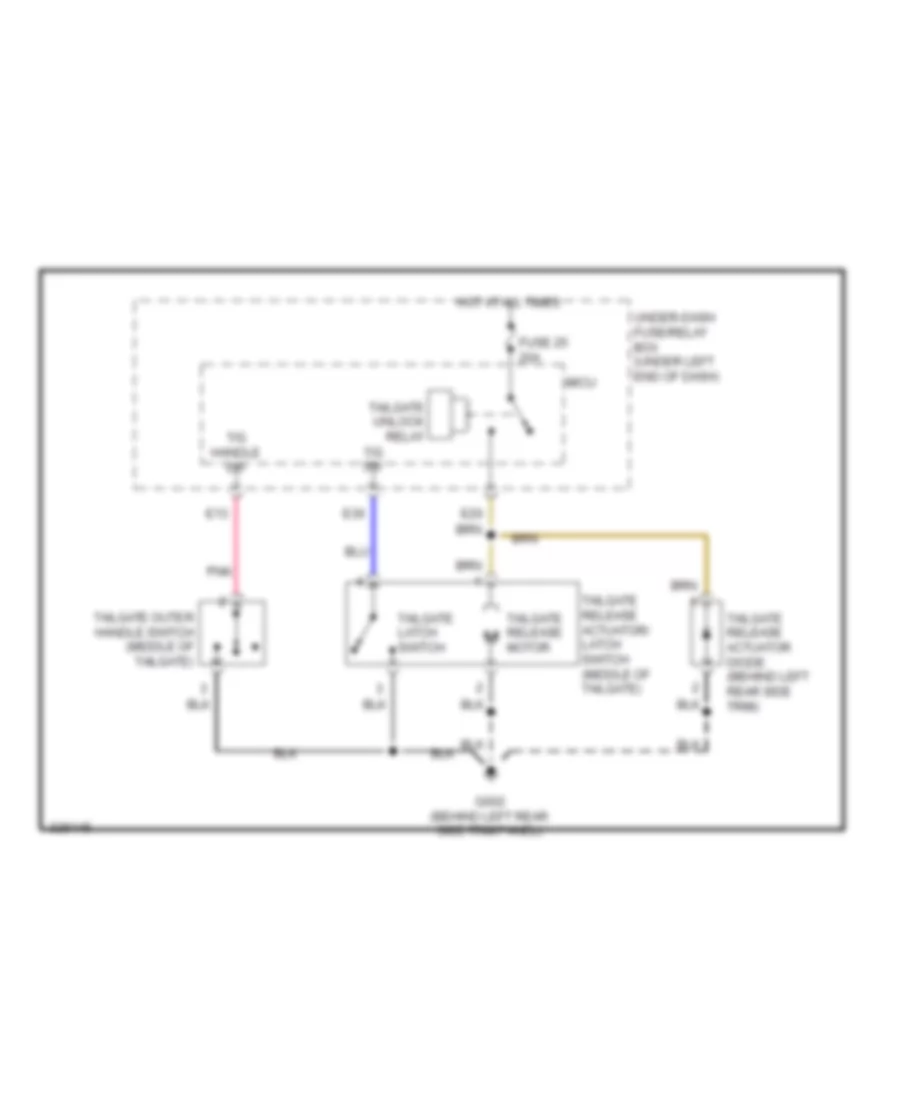
Forced Entry Wiring Diagram (2 of 2) for Acura RDX 2010
List of elements for Forced Entry Wiring Diagram (2 of 2) for Acura RDX 2010:
- (behind left rear side trim panel) g602
- (left rear door) left rear door lock actuator/knob switch
- (middle of tailgate) tailgate release actuator/latch switch
- (not used)
- 5v stabilize circuit/ controller area network controller
- Audio unit
- Automatic lighting control unit (behind left rear side trim)
- B-can
- Body controller area network transceiver
- Bus
- C14
- Control block
- Door lock actuator
- Driver's door lock switch lock
- Driver's door switch (left "b" pillar)
- Except technology
- Front passenger's door lock lock switch
- Front passenger's door switch (right "b" pillar)
- Front passenger's power window switch
- Fuse 10a
- Fuse 15a
- G451 (under left side of dash)
- G501 (behind left side of dash)
- G502 (under middle of dash)
- G504 (behind glove box)
- G505 (behind glove box)
- G601 (behind left rear side trim panel)
- G602 (behind left rear side trim panel)
- Gauge control module
- Handle pulled
- Hot at all times
- Ignition key switch
- Ignition key switch/key light
- Immobilizer keyless control unit (on steering column cover)
- J13
- J15
- J16
- J19
- K14
- Key in ignition
- Keyless buzzer (behind left side of front bumper)
- Left rear door switch (left "c" pillar)
- Left unlock
- Lock
- Main gnd
- Navigation display unit (technology package) (under middle of dash)
- Package
- Pgnd
- Pnk
- Power distribution system
- Power window master switch
- Rear door lock knob switch
- Right rear door switch (right "c" pillar)
- Security
- Security +
- Security -
- Security hood switch (behind middle of front bumper)
- Security indicator
- Security indicator blinking circuit
- Tailgate latch switch
- Tailgate outer handle switch (middle of tailgate)
- Tailgate release actuator
- Tailgate release actuator diode (behind left rear side trim)
- Technology package
- Under-dash junction box (under left side of dash)
- Under-hood fuse/relay box (left rear of engine compt)
- Unlock
Immobilizer Wiring Diagram for Acura RDX 2010
List of elements for Immobilizer Wiring Diagram for Acura RDX 2010:
- (behind left rear side trim) automatic lighting control unit
- (under middle of dash) g502
- +b backup
- A12
- A15
- A31
- A38
- A43
- A44
- B-can
- B12
- B23
- Body controller area network transceiver
- Bus
- C14
- C36
- C44
- Computer data lines system
- Controller area 5v stabilize circuit/
- Driver's circuit
- Engine controls system
- F10
- F11
- F24
- Fp+
- Fp-
- Fpc
- Fpcd
- Fuel pmp ctrl
- Fuel pmp ctrl mod diag
- Fuel pump
- Fuel pump control module (left "c" pillar)
- Fuel pump ctrl
- Fuel tank unit (in top of fuel tank)
- Fuse 10a
- Fuse 15a
- Fuse 20a
- G101 (left side of engine)
- G501 (behind left side of dash)
- G601 (behind left rear side trim panel)
- Gauge control module
- Gnd
- Hot at all times
- Hot in on or start
- Ig1
- Ig1 fuel pump
- Ign in
- Ignition key switch
- Ignition key switch/ key light
- Immobilizer keyless control unit (on steering column cover)
- Immobilizer system indicator
- J/c c103
- J/c c104 (left rear of engine compt)
- J19
- K-line
- Key in ignition
- Key sw
- Micu
- Network controller
- Parking brake check circuit
- Parking brake switch (at base of parking brake lever)
- Pcm (left front of engine compt)
- Pgm-fi main relay 1
- Pgm-fi main relay 2
- Pnk
- Power distribution system
- R11
- R12 (not used)
- Rly ctrl
- S-net
- S4 (thermal joint)
- Scs
- Serial comm sig in
- Service check in
- Under-dash fuse/relay box (under left end of dash)
- Under-dash junction box (under left side of dash)
- Under-hood fuse/relay box (left rear of engine compt)
- Vbu
BODY CONTROL MODULES
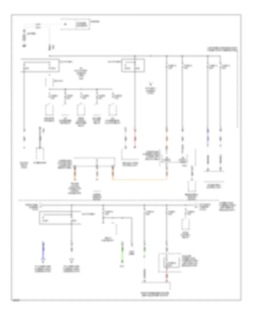
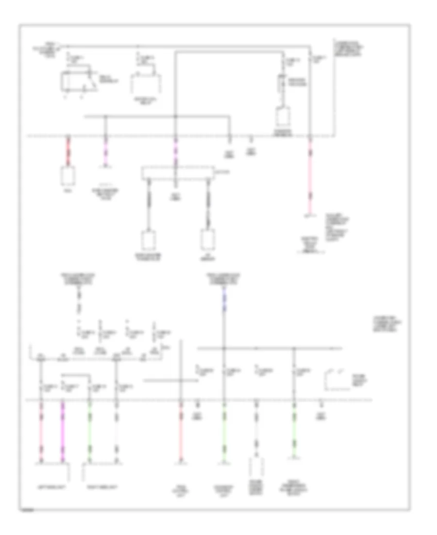
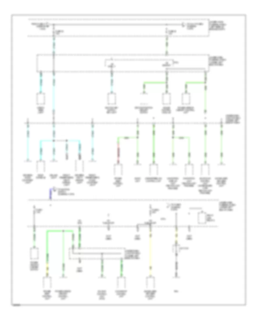
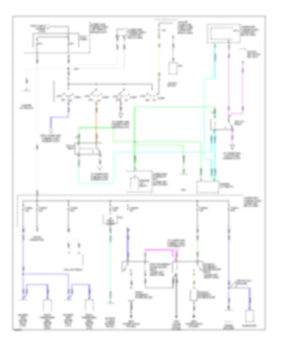
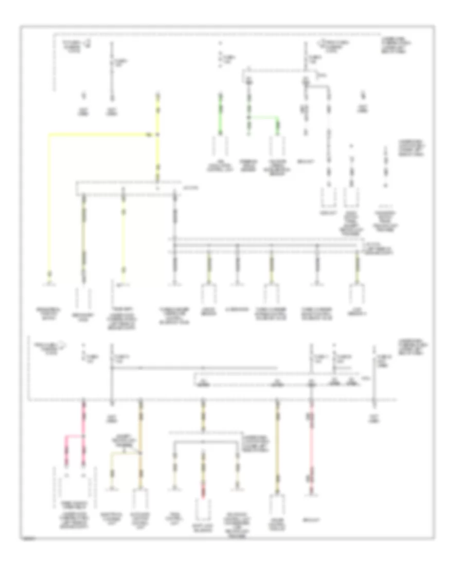
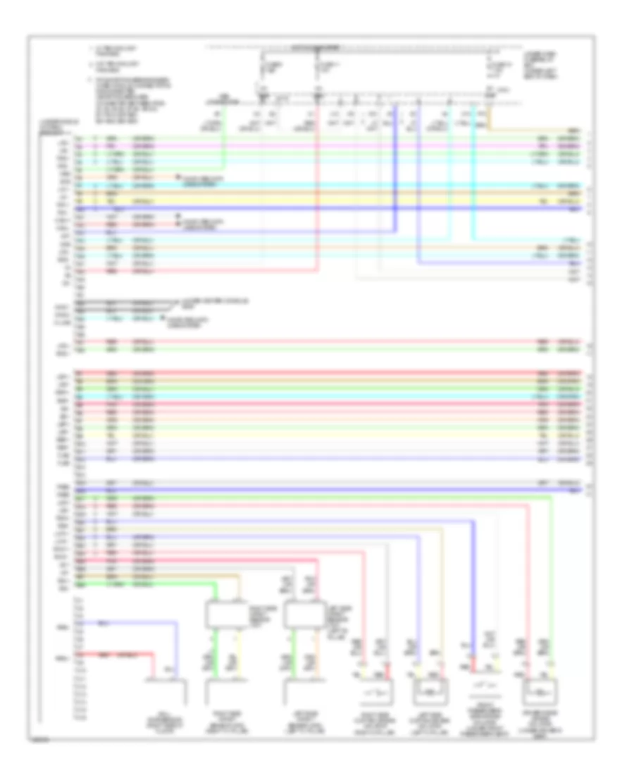
Body Control Modules Wiring Diagram (1 of 2) for Acura RDX 2010
List of elements for Body Control Modules Wiring Diagram (1 of 2) for Acura RDX 2010:
- (not used)
- (option connector)
- +b backup
- +b d/l
- +b h/l hi main
- +b h/l lo main
- +b haz
- +b intr lt
- +b l h/l hi
- +b l h/l lo
- +b p/seat lumb
- +b r h/l lo
- +b small
- +b stop & horn
- +b tpms
- Acc radio
- Anti-lock brakes system
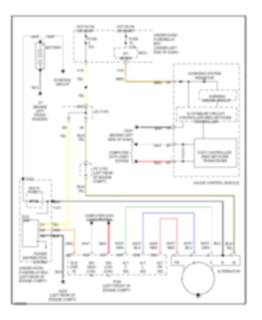
- Anti-theft & starting/charging systems
- Atp-s
- E16
- E25
- E26
- E33
- E34
- Engine controls system
- Exterior lights system
- F18
- F19
- F20
- F25
- F29
- F30
- F32
- F33
- F34
- Fr washer mtr
- Fr wiper (as)
- Fr wiper (hi)
- Fr wiper (lo)
- Fuse (not used)
- Fuse 10a
- Fuse 20a
- Fuse 30a
- Fuse 7.5a
- G16
- G451 (under left side of dash)
- G601 (behind left rear side trim panel)
- Headlights system
- Hot at all times
- Hot in acc or on
- Hot in on
- Hot in on or start
- Hot in start
- Ig1 4wd
- Ig1 abs
- Ig1 fuel pump
- Ig1 meter
- Ig1 ods
- Ig1 srs
- Ig1 wiper
- Ig2 daylight
- Ig2 hac
- Ill+
- Ill-
- Instrument cluster system
- Interior lights system
- Keysol
- Micu
- Micu chk
- Micu service check connector
- N10
- Not used
- P-gnd
- P/w timer
- P10
- Power distribution system
- Power tops & power windows systems
- Q10
- Q12
- Q13
- Q14
- Q15
- Q16
- R10
- R11
- R12
- R17
- R18
- R19
- R20
- Red
- Rr washer mtr
- S-gnd
- Seats system
- Shift interlock system
- Small rly-
- Starting/charging system
- Stop sw
- Sts
- T/g sw
- Under-dash fuse/relay box (under left end of dash)
- Wiper/ washer system
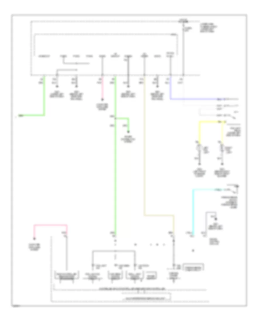
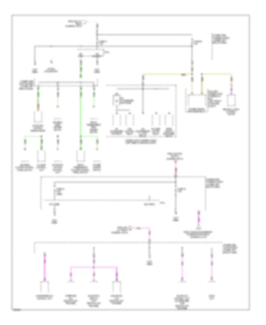
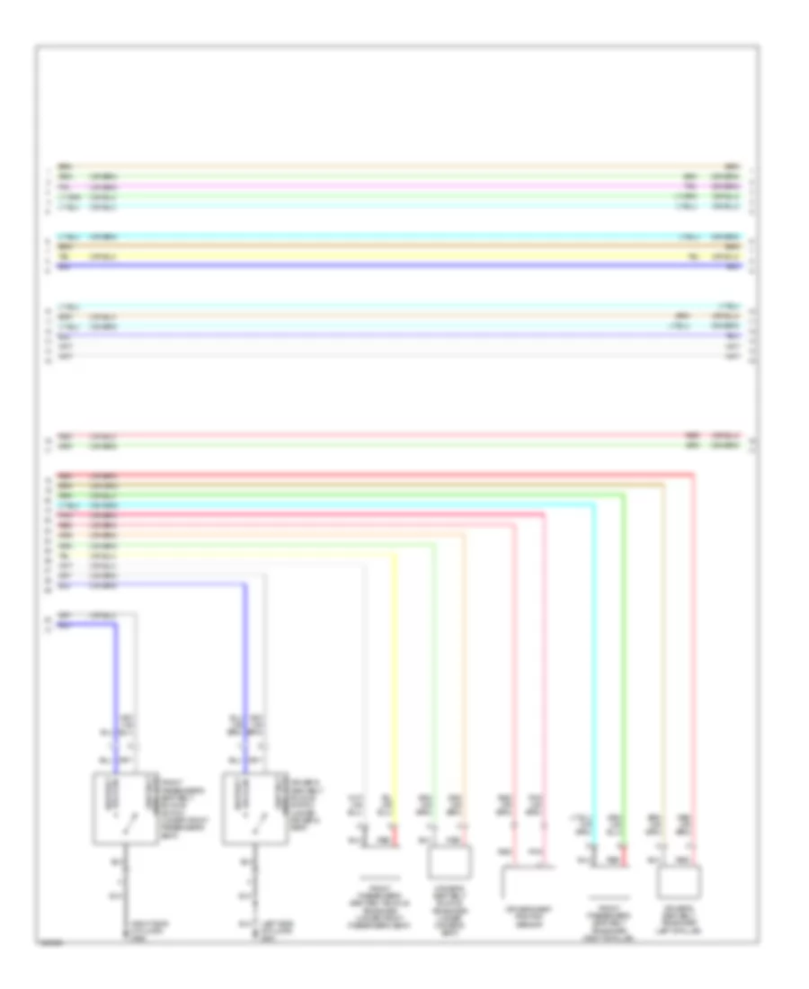
Body Control Modules Wiring Diagram (2 of 2) for Acura RDX 2010
List of elements for Body Control Modules Wiring Diagram (2 of 2) for Acura RDX 2010:
- (not used)
- (option connector)
- Acc
- Acs
- Air conditioning system
- Anti-theft & door locks systems
- Anti-theft & starting/ charging systems
- Anti-theft, door locks & interior lights systems
- Atpp
- Atpr
- B-can
- Back lt-
- Combi gnd (light)
- Combi gnd (wiper)
- Computer data lines system
- Courtesy as
- Courtesy dr
- Dim sw
- Door locks & anti-theft systems
- Door locks & interior lights systems
- Door locks system
- Dr locks
- E13
- E14
- E15
- E17
- E20
- E21
- E31
- E36
- E37
- E39
- E40
- Engine controls system
- Exterior lights system
- F11
- F14
- F21
- F23
- F26
- F27
- F28
- Fog lt sw
- Fr door sw (as)
- Fr door sw (dr)
- Fr fog rly cl-
- Fr washer sw
- Fr wiper hi & lo sw
- Fr wiper int vol+
- Fr wiper mist sw
- Fuse 10a
- Fuse 15a
- Fuse 7.5a
- G13
- G501 (behind left side of dash)
- H/l off sw
- H/l on sw
- Haz sw
- Headlights system
- Hood sw
- Horns
- Horns system
- Hot at all times
- Interior lights system
- Intr lt-
- K-line
- Kc dr lock
- Kc dr unlock
- Key sw
- Keyless buzzer
- L turn sig
- M10
- Memory, shift interlock & transmissions systems engine controls, mirrors, interior lights & transmissions systems
- Micu
- N13
- Navigation & sound systems
- P-pin sw
- Passing sw
- Pnk
- Power distribution system
- Q11
- R turn sig
- R13
- R16
- Red
- Rem as lock
- Rem as unlock
- Rem dr lock
- Rem dr unlock
- Rr door sw (as)
- Rr door sw (dr)
- Rr washer sw
- Rr wiper as
- Rr wiper rly cl
- Rr wiper sw
- S-gnd2
- S-net
- S10
- S11
- S12
- S13
- S14
- S15
- S16
- S17
- S18
- S19
- S20
- Scs
- Scty1
- Shift interlock system
- Sil as unlock
- Sil dr lock
- Sil dr unlock
- Sil ra unlock
- Sil rd unlock
- Small lt sw
- T/g handle sw
- T/g unlock rly
- T10
- T11
- T12
- T13
- T14
- T15
- T16
- T17
- T18
- T19
- T20
- T21
- T22
- T23
- T24
- T25
- T26
- T27
- T28
- T29
- T30
- T31
- T32
- T33
- T34
- Trunk sw
- Turn l sw
- Turn r sw
- Under-dash fuse/relay box (under left end of dash)
- Under-hood fuse/relay box (left rear of engine compt)
- Vac strld
- Wiper int & lo sw
- Wiper/ washer system
- Wiper/washer system
COMPUTER DATA LINES
Computer Data Lines Wiring Diagram (1 of 3) for Acura RDX 2010
List of elements for Computer Data Lines Wiring Diagram (1 of 3) for Acura RDX 2010:
- (behind left side of dash) g501
- (not used)
- (not used) c210
- (under middle of dash) srs unit
- +b backup
- A10
- A11
- A12
- A19
- A20
- A24
- A31
- A36
- A37
- A42
- B12
- Dlc (data link connector) (under left side of dash)
- E17
- E18
- F11
- F14
- F28
- Fuse 10a
- Fuse 15a
- G101 (left side of engine)
- G12
- G13
- G601 (behind left rear side trim panel)
- Hot at all times
- Immobilizer keyless control unit (on steering column cover)
- J/c c103
- J/c c207 (under left side of dash)
- J/c c401 (behind middle of dash)
- J/c c402 (behind middle of dash)
- J18
- J21
- K-line
- Micu
- Micu chk
- Micu service check connector
- Pcm (left front of engine compt)
- Pnk
- Red
- S-gnd
- Scs
- Sh-awd control unit (4wd) (behind left rear side trim panel)
- Sig high
- Sig low
- Steering angle sensor (in steering column cover)
- Tpms control unit (under left side of dash)
- Under-dash fuse/relay box (under left end of dash)
- Under-dash junction box (under left side of dash)
- Under-hood fuse/relay box (left rear of engine compt)
- Vsa modulator control unit (right side of engine compt)
- Wen
- Yaw rate-lateral acceleration sensor (under middle of dash)
Computer Data Lines Wiring Diagram (2 of 3) for Acura RDX 2010
List of elements for Computer Data Lines Wiring Diagram (2 of 3) for Acura RDX 2010:
- (option connector)
- A10 b-can
- A10 ecu bus+ (ga-net)
- A13 ga-net audio r+
- A14 ga-net audio r-
- A15 ga-net audio l+
- A16 ga-net audio l-
- A20 can lo
- A20 ecu bus- (ga-net)
- A24
- A29 bus sh (ga-net)
- A30
- A31 bus - (ga-net)
- A32 ga-net audio sh
- A40
- A7 can hi bus + (ga-net)
- A9 sh ecu bus+ (ga-net)
- Acuralink control unit (xm receiver) (usa: technology package) (behind glove box)
- Automatic lighting control unit (behind left rear side trim)
- B-can
- Body controller area network transceiver
- Bus + (ga-net)
- Bus - (ga-net)
- Bus sh (ga-net)
- C14
- Can-h
- Can-l
- Climate control unit (behind glove box)
- Control block
- Controller area network controller 5v stabilize circuit/
- Ecu bus+ (ga-net)
- Ecu bus- (ga-net)
- Fast controller area network transceiver
- Front passenger's power window switch
- Gauge control module
- J/c c403 (under middle of dash)
- J19
- L10
- Micu
- Navigation display unit
- Navigation unit (under middle of dash)
- Pnk
- Power seat control unit (underside of driver's seat)
- Power window master switch
- Red
- Sh disp bus (ga-net)
- Technology package
- Uart
- Under-dash fuse/relay box (under left end of dash)
- Under-dash junction box (under left side of dash)
- Usa & canada: technology package
- W/ technology package
- W/o technology package
Computer Data Lines Wiring Diagram (3 of 3) for Acura RDX 2010
List of elements for Computer Data Lines Wiring Diagram (3 of 3) for Acura RDX 2010:
- (under middle
- (under middle of dash) j/c c406
- A10
- A13
- A14
- Audio l+ (ga-net)
- Audio l- (ga-net)
- Audio r+ (ga-net)
- Audio r- (ga-net)
- Audio sh (ga-net)
- Audio unit
- B10 bus - (ga-net)
- B13 audio r- (ga-net)
- B14 audio l- (ga-net)
- B3 bus sh (ga-net)
- B4 audio sh (ga-net)
- B5 audio r+ (ga-net)
- B6 audio l+ (ga-net)
- B9 bus + (ga-net)
- Bus + (ga-net)
- Bus - (ga-net)
- Bus sh (ga-net)
- Handsfreelink control unit (under center console)
- J/c c404
- J/c c407 (under center console)
- J/c c408 (under center console)
- K-line
- Of dash)
- Pnk
- Red
- Usb adapter unit (under center console)
- W/ technology package
- W/o technology package
- Xm receiver
COOLING FAN
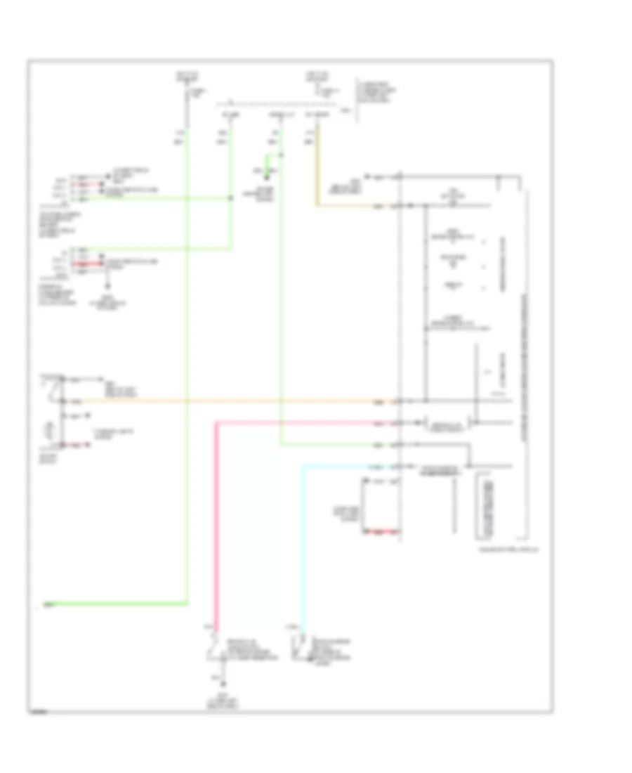
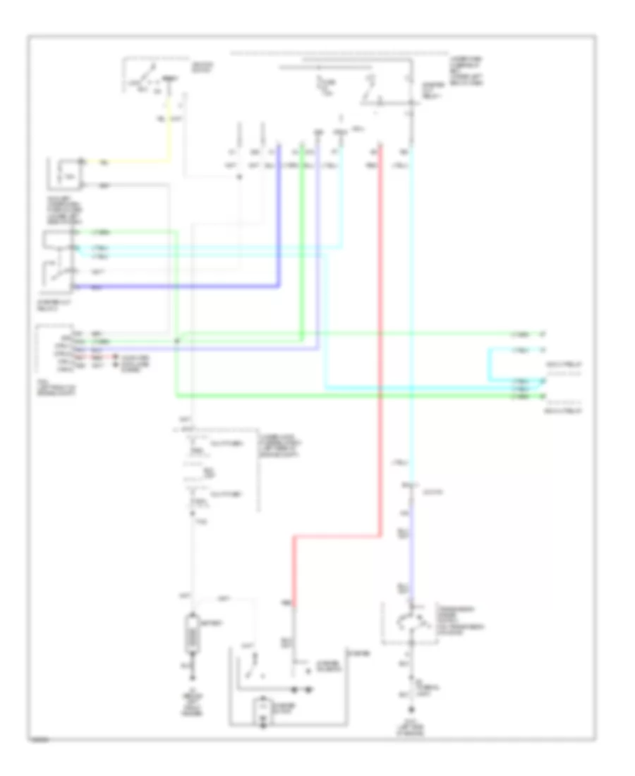
Cooling Fan Wiring Diagram for Acura RDX 2010
List of elements for Cooling Fan Wiring Diagram for Acura RDX 2010:
- (front of engine compt) a/c condenser fan motor
- (not used)
- A/c condenser fan diode
- A/c condenser fan relay
- A/c pressure sensor (right side of engine compt)
- A16
- A19
- A33
- B23
- B33
- Ect sensor 1 (rear of engine)
- Ect sensor 2 (front of engine compt)
- F11
- F12
- F14
- Fan control relay
- Fuse 10a
- Fuse 30a
- Fuse 7.5a
- G12
- G201 (left front of engine compt)
- G202 (left rear of engine compt)
- Hi fan ctrl (fanh)
- Hot at all times
- Hot in on
- Hot w/ pgm-fi sub-relay energized
- J/c c105 (rear of engine)
- J/c c207 (under left side of dash)
- Lo fan ctrl (fanl)
- Pcm (left front of engine compt)
- Radiator fan diode
- Radiator fan motor connector (front of engine compt)
- Radiator fan relay
- Red
- Ref volt (vcc6)
- Sens gnd (sg2)
- Sens gnd (sg6)
- Sens in (acpd)
- Sens in (ect1)
- Sens in (ect2)
- Under-dash fuse/relay box (under left end of dash)
- Under-hood fuse/relay box (left rear of engine compt)
CRUISE CONTROL
Cruise Control Wiring Diagram (1 of 2) for Acura RDX 2010
List of elements for Cruise Control Wiring Diagram (1 of 2) for Acura RDX 2010:
- A11
- A17
- A18
- A20
- A24
- A25
- A34
- A35
- A36
- A37
- A39
- A40
- App sensor (under left side of dash)
- B11
- B28
- C12
- C20
- C21
- C39
- C43
- Computer data lines system
- Drive in
- Etcs control relay
- F10
- Fuse 12 15a
- Fuse 19 15a
- Fuse 21 15a
- G101 (left side of engine)
- Hot at all times
- Ign in
- J/c c103
- Mtr+ out
- Mtr- out
- Output shaft (countershaft) speed sensor (on transmission housing)
- Pcm (left front of engine compt)
- Pgm-fi main relay 1
- Pwr in
- Red
- Ref volt
- Rly ctrl
- S2 (thermal joint)
- Sens gnd
- Sens in
- Sig high
- Sig low
- Sw in
- Tp sensor/throttle actuator (on throttle body)
- Transmission range switch (on transmission housing)
- Under-hood fuse/relay box (left rear of engine compt)
Cruise Control Wiring Diagram (2 of 2) for Acura RDX 2010
List of elements for Cruise Control Wiring Diagram (2 of 2) for Acura RDX 2010:
- 5v stabilize circuit/controller area network controller
- Area network fast controller
- Brake pedal position switch (under left side of dash)
- C11
- Cable reel (b: top of steering column) (c: in steering wheel)
- Cancel switch
- Computer data lines system
- Cruise control combination switch
- Cruise control dimming circuit
- Cruise control ind
- Cruise control main switch ind
- F15
- F25
- F30
- F31
- Fuse 10 7.5a
- Fuse 15a
- G16
- G501 (behind left side of dash)
- G502 (under middle of dash)
- Gauge control module
- Horn switch
- Hot in on or start
- Ig1 meter
- Interior lights system
- Main switch
- Micu
- Nca
- P10
- Red
- Resume switch
- Set switch
- Steering wheel
- Transceiver
- Transmissions system
- Under-dash fuse/relay box (under left end of dash)
- Warning driver circuit
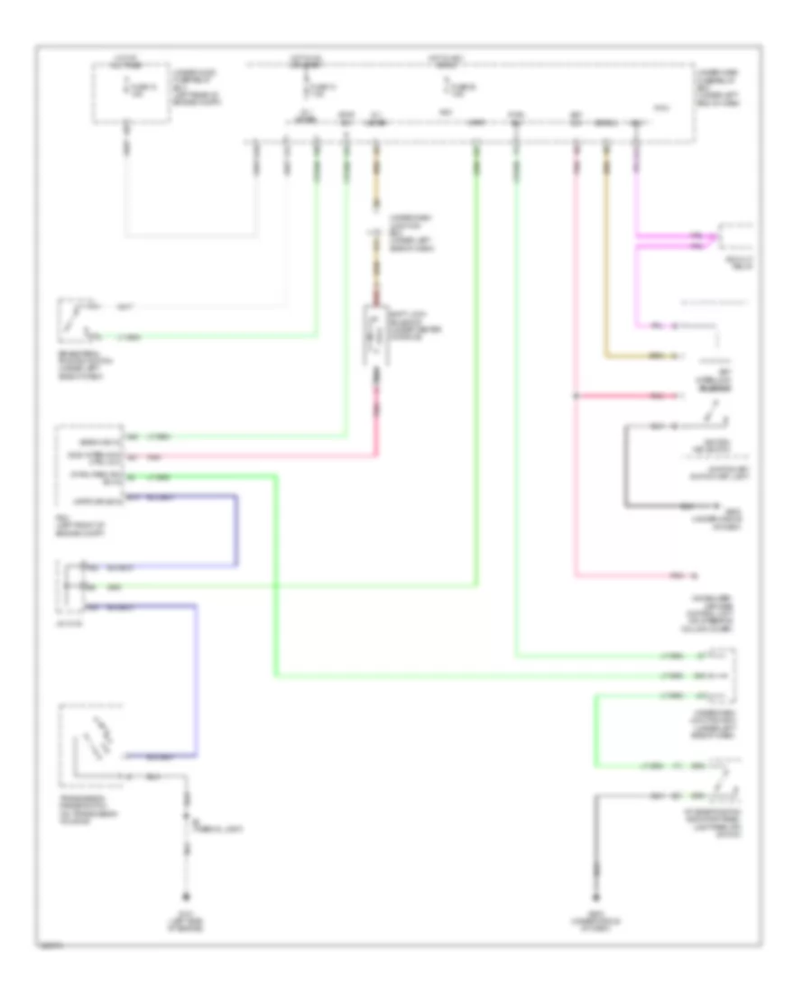
DEFOGGERS
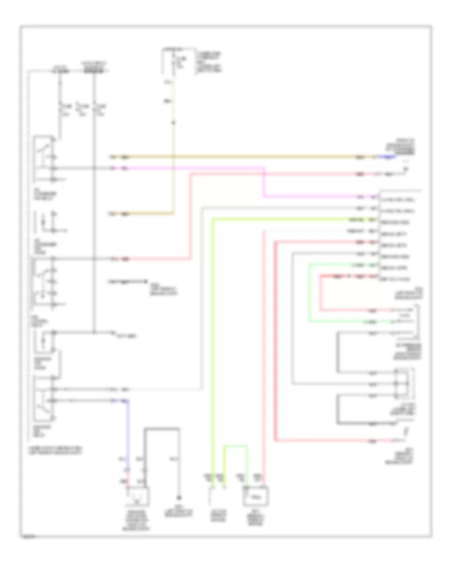
Heated Mirrors Wiring Diagram for Acura RDX 2010
List of elements for Heated Mirrors Wiring Diagram for Acura RDX 2010:
- (behind glove box) g505
- (behind left side of dash) g501
- (under right side of dash) g571
- A21
- A24
- Auxiliary under-hood fuse/relay box (left front of engine compt)
- B16
- Bus data
- Climate control unit (behind glove box)
- Def-led
- Defogger
- Driver's climate control panel switch
- E10
- F17
- Front passenger's climate control panel switch
- Fuse 36 10a
- G12
- G502 (under middle of dash)
- Gnd
- Hot in on
- Ig2
- Ig2 hac
- Left power mirror (driver's door)
- Micu
- Mirror defogger ind
- Mirror defogger switch
- Pnk
- Power mirror defogger relay
- Q16
- Rear window defogger relay
- Rec-led
- Right power mirror (front passenger's door)
- Rr def led
- Rr def rly
- Sw in 1
- Sw in 2
- Sw in 3
- Sw in 4
- Sw out 3
- Sw out 4
- Under-dash fuse/relay box (under left end of dash)
- Under-dash junction box (under left side of dash)
- Under-hood fuse/relay box (left rear of engine compt)
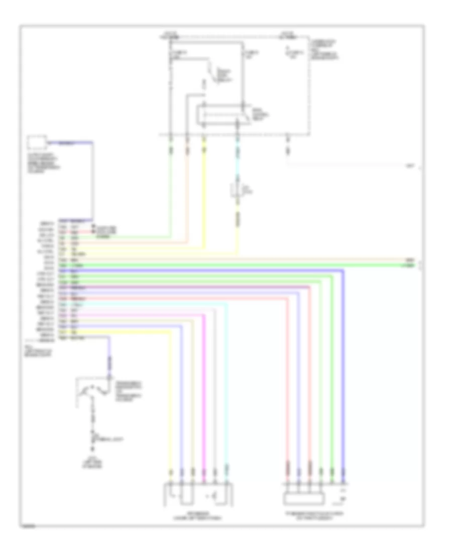
Rear Defogger Wiring Diagram for Acura RDX 2010
List of elements for Rear Defogger Wiring Diagram for Acura RDX 2010:
- A21
- A24
- Auxiliary under-hood fuse/relay box (left front of engine compt)
- B16
- Bus data
- Climate control unit (behind glove box)
- Def-led
- Driver's climate control panel switch
- F17
- Front passenger's climate control panel switch
- Fuse 30a
- Fuse 36 10a
- G12
- G502 (under middle of dash)
- G571 (under right side of dash)
- G602 (behind left rear side trim panel)
- Gnd
- Has built-in rear window defogger switch
- Hot at all times
- Hot in on
- Ig2
- Ig2 hac
- Micu
- Pnk
- Power mirror defogger relay
- Q16
- Rear window defogger
- Rear window defogger ind
- Rear window defogger relay
- Rec-led
- Red
- Rr def led
- Rr def rly
- Sw in 1
- Sw in 2
- Sw in 3
- Sw in 4
- Sw out 3
- Sw out 4
- Under-dash fuse/relay box (under left end of dash)
- Under-hood fuse/relay box (left rear of engine compt)
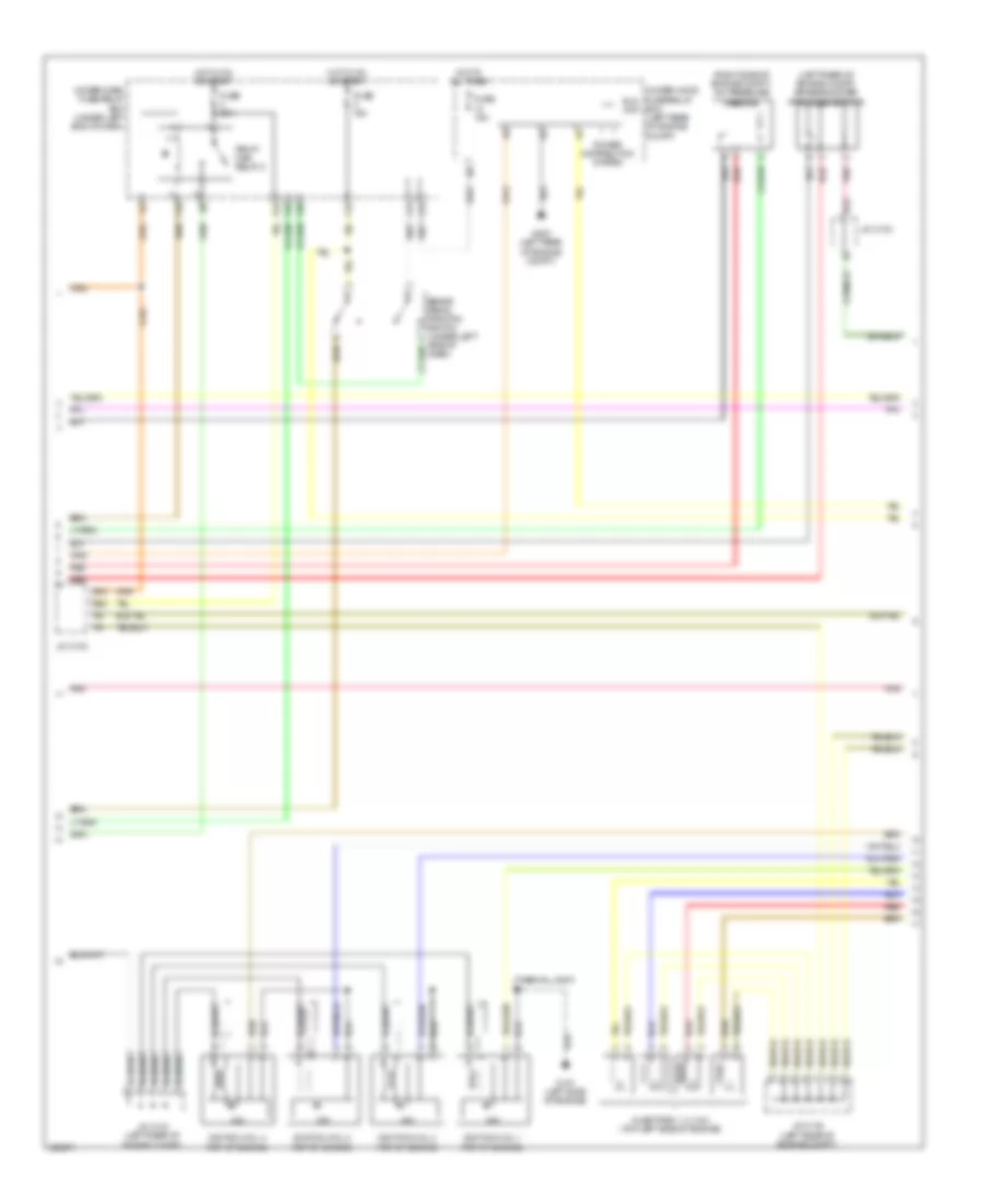
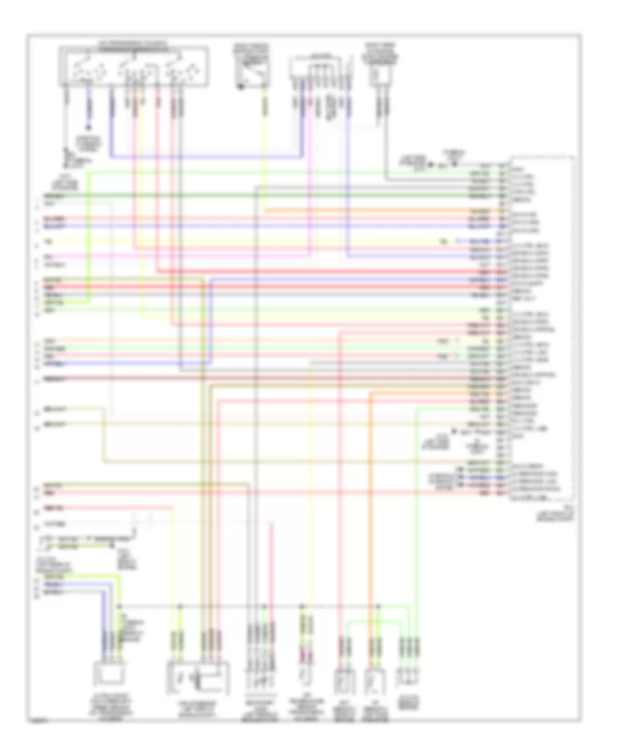
ENGINE PERFORMANCE
2.3L
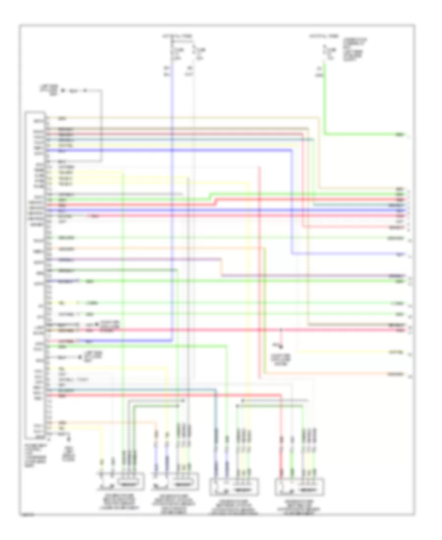
2.3L, Engine Performance Wiring Diagram (1 of 6) for Acura RDX 2010
List of elements for 2.3L, Engine Performance Wiring Diagram (1 of 6) for Acura RDX 2010:
- (not used)
- (under middle of vehicle) evap canister vent shut valve
- A10
- A11
- A12
- A13
- A14
- A15
- A16
- A17
- A18
- A19
- A20
- A21
- A22
- A23
- A24
- A25
- A26
- A27
- A28
- A29
- A30
- A31
- A32
- A33
- A34
- A35
- A36
- A37
- A38
- A40
- A41
- A42
- A43
- A44
- Air conditioning system
- App sensor (under left side of dash)
- B11
- B13
- Barometer sensor
- Can high
- Can low fuel pump ctrl mod diagnosis a39
- Computer data lines system
- Cooling fans system
- Ect sensor 2 (front of engine compt)
- Eld unit in
- Etcs control relay
- F10
- F16
- F18
- Fp+
- Fp-
- Fpc
- Fpcd
- Ftp sensor (under middle of vehicle)
- Fuel pump
- Fuel pump control module (left "c" pillar)
- Fuel pump ctrl
- Fuel tank unit (in top of fuel tank)
- Fuse 15a
- G401
- G601 (behind left rear side trim panel)
- Gnd
- High fan ctrl
- Hot at all times
- Ig1
- Ignition coil relay
- Interlk ctrl out
- J/c c103
- J/c c207 (under left side of dash)
- Low fan ctrl
- Memory systems
- Park pin sw in
- Pcm (left front of engine compt)
- Pgm-fi main relay 1
- Pgm-fi sub- relay
- Pnk
- Psp switch (right rear of engine compt)
- Pwr in
- Red
- Ref volt
- Rly ctrl
- Sens gnd
- Sens in
- Serial communication sig in
- Service check in
- Shift interlock system
- Starting/charging system
- Strld
- Strly
- Sw in
- Under-hood fuse/relay box (left rear of engine compt)
- Veh spd out
- Vlv ctrl
- Write enable in
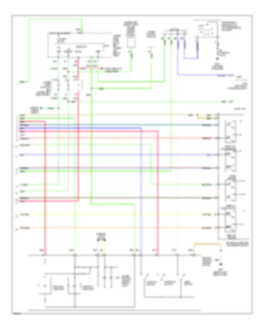
2.3L, Engine Performance Wiring Diagram (2 of 6) for Acura RDX 2010
List of elements for 2.3L, Engine Performance Wiring Diagram (2 of 6) for Acura RDX 2010:
- (left rear of engine compt) brake booster pressure sensor
- (right side of engine compt) a/c pressure sensor
- (thermal joint) s1
- B18
- B22
- B23
- Brake pedal position switch (under left side of dash)
- Eld unit
- F10
- F15
- F24
- F25
- F30
- F31
- Fuse 15a
- Fuse 20a
- G101 (left side of engine)
- G16
- G202 (left rear of engine compt)
- Hot at all times
- Hot in on or start
- Icm
- Ignition coil 1 (top of engine)
- Ignition coil 2 (top of engine)
- Ignition coil 3 (top of engine)
- Ignition coil 4 (top of engine)
- Injectors 1, 2, 3 & 4 (top left side of engine)
- J/c c103
- J/c c104 (left rear of engine compt)
- Pgm-fi main relay 2
- Pnk
- Power distribution system
- Red
- Under-dash fuse/relay box (under left end of dash)
- Under-hood fuse/relay box (left rear of engine compt)
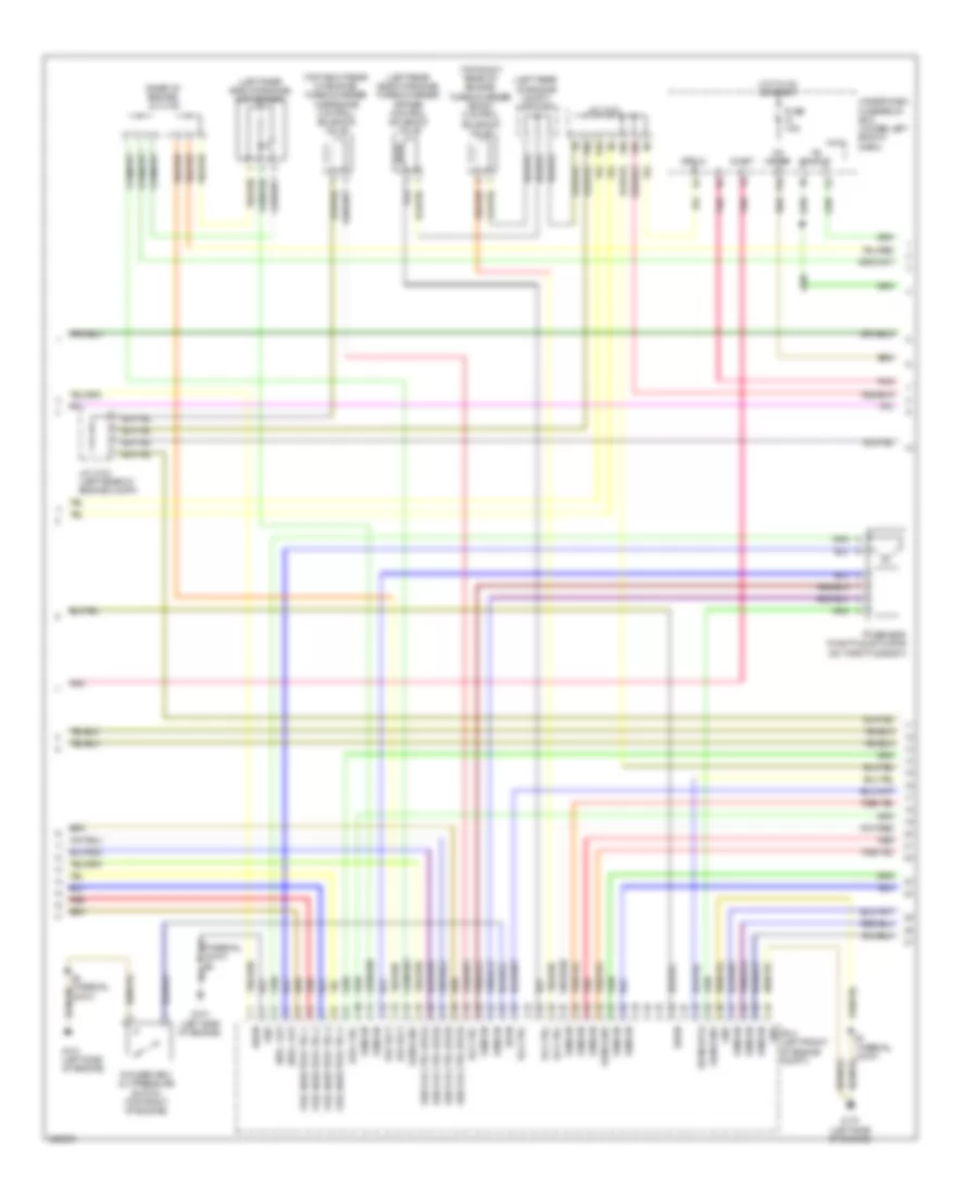
2.3L, Engine Performance Wiring Diagram (3 of 6) for Acura RDX 2010
List of elements for 2.3L, Engine Performance Wiring Diagram (3 of 6) for Acura RDX 2010:
- (left rear of engine compt) j/c c104
- (left rear side of engine) map sensor
- (left rear side of engine) turbocharger bypass control solenoid valve
- (rear of engine) j/c c105
- (top right rear of engine) turbocharger boost control solenoid valve
- (top right rear of engine) turbocharger wastegate control solenoid valve
- +b backup
- A10
- A19
- A20
- B10
- C10
- C11
- C12
- C13
- C14
- C15
- C16
- C17
- C18
- C19
- C20
- C21
- C22
- C23
- C24
- C25
- C26
- C27
- C28
- C29
- C30
- C31
- C32
- C33
- C34
- C35
- C36
- C37
- C38
- C39
- C40
- C41
- C42
- C43
- C44
- Fuel injector ctrl 1
- Fuel injector ctrl 2
- Fuel injector ctrl 3
- Fuel injector ctrl 4
- Fuse 7.5a
- G101 (left side of engine)
- Gnd
- Hot in on or start
- Htr ctrl
- Ig1 meter
- Ign coil ctrl (pls1)
- Ign coil ctrl (pls2)
- Ign coil ctrl (pls3)
- Ign coil ctrl (pls4)
- Ign in
- J/c c103
- J/c c104 (left rear of engine compt)
- Micu
- Mtr + out
- Mtr - out
- P10
- Pcm (left front of engine compt)
- Pnk
- Red
- Ref volt
- Rocker arm oil pressure switch (top front of engine)
- S-net
- S4 (thermal joint)
- Sens gnd
- Sens in
- Strld
- Sw in
- Sw in (op4)
- Tp sensor/ throttle actuator (on throttle body)
- Under-dash fuse/relay box (under left end of dash)
- Vlv ctrl
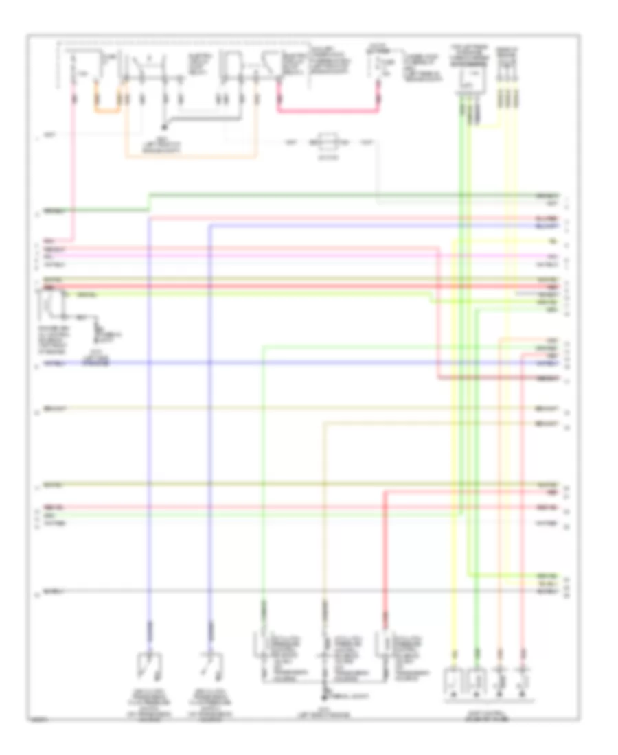
2.3L, Engine Performance Wiring Diagram (4 of 6) for Acura RDX 2010
List of elements for 2.3L, Engine Performance Wiring Diagram (4 of 6) for Acura RDX 2010:
- (on transmission housing) input shaft (mainshaft) speed sensor
- (right side of engine compt) electric vacuum pump
- (thermal joint) s4
- 4th clutch transmission fluid pressure switch (on transmission housing)
- 5v stabilize circuit/ controller area network controller
- A/f sensor (right side of engine compt)
- A/t gear position dimming circuit
- A/t gear position ind drive circuit
- A/t temperature ind
- B16
- B17
- B20
- B21
- Braided
- C16
- C17
- Cable reel (connector b: top of steering column) (connector c: in steering wheel)
- Ckp sensor (right side of engine compt)
- Cmp sensor a (right of engine)
- Cmp sensor b (right of engine)
- Computer data lines system
- Cruise control combination switch
- Fast controller area network transceiver
- Fuse 10a
- G101 (left side of engine)
- G401
- G501 (behind left side of dash)
- G502 (under middle of dash)
- Gauge control module
- Hot at all times
- J/c c103
- J/c c104 (left rear of engine) compt)
- Knock sensor (front of engine)
- Lcd back light
- Mil ind
- Pnk
- Red
- S4 (thermal joint)
- Shift ind brightness control & dimming circuit
- Shift ind driver circuit
- Steering wheel
- Steering wheel downshift (-) switch
- Steering wheel upshift (+) switch
- Under-hood fuse/relay box (left rear of engine compt)
- Vtc oil control solenoid valve (front side of engine)
- Warning driver circuit
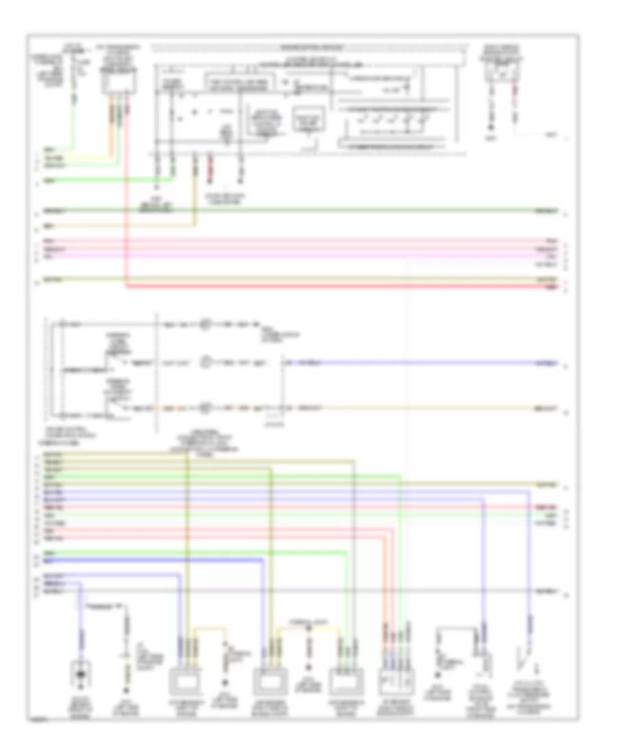
2.3L, Engine Performance Wiring Diagram (5 of 6) for Acura RDX 2010
List of elements for 2.3L, Engine Performance Wiring Diagram (5 of 6) for Acura RDX 2010:
- (rear of engine) j/c c105
- (top left rear of engine) turbocharger boost sensor
- 2nd clutch transmission fluid pressure switch (on transmission housing)
- 3rd clutch transmission fluid pressure switch (on transmission housing)
- 7.5a
- A/t clutch pressure control solenoid valve a (on transmission housing)
- A/t clutch pressure control solenoid valve b (on transmission housing)
- A/t clutch pressure control solenoid valve c (on transmission housing)
- A21
- Auxiliary under-hood fuse/relay box (left front of engine compt)
- Electric vacuum pump relay 1
- Electric vacuum pump relay 2
- Fuse
- Fuse 15a
- G101 (left side of engine)
- G201 (left front of engine compt)
- Hot at all times
- J/c c103
- Pnk
- Red
- Rocker arm oil control solenoid (top front of engine)
- S1 (thermal joint)
- S2 (thermal joiont)
- Shift control solenoid valves
- Under-hood fuse/relay box (left rear of engine compt)
2.3L, Engine Performance Wiring Diagram (6 of 6) for Acura RDX 2010
List of elements for 2.3L, Engine Performance Wiring Diagram (6 of 6) for Acura RDX 2010:
- (left side of engine) g101
- (not used)
- (on transmission housing) transmission range switch
- (right rear of engine) evap canister purge valve
- (right side of engine compt) oil pressure switch
- (thermal joint) s2
- A14
- A15
- A22
- A23
- Alternator c sig
- Alternator fr sig
- Alternator l sig
- Atf temperature sensor (transmission housing)
- B10
- B11
- B12
- B13
- B14
- B15
- B16
- B17
- B18
- B19
- B20
- B21
- B22
- B23
- B24
- B25
- B26
- B27
- B28
- B29
- B30
- B31
- B32
- B33
- B34
- B35
- B36
- B37
- B38
- B39
- B40
- B41
- B42
- B43
- B44
- Braided wire
- Drive in (atpd)
- Drive in (atpfwd)
- Drive in (atpn)
- Drive in (atpp)
- Drive in (atpr)
- Drive in (atprvs)
- Drive in (atps)
- Ect sensor 1 (rear of engine)
- G101 (left side of engine)
- Gnd
- Htr ctrl
- Iat sensor 2 (left side of engine)
- J/c c103
- J/c c104 (left rear of engine compt)
- J/c c105 (rear of engine)
- Maf/iat sensor (left side of engine compt)
- Output shaft (countershaft) speed sensor (on transmission housing)
- Pcm (left front of engine compt)
- Pnk
- Red
- Ref volt
- Rly ctrl
- S1 (thermal joint)
- S2 (thermal joint)
- S3 (thermal joint) (rear of engine)
- Secondary ho2s (left rear of engine compt)
- Sens gnd
- Sens in
- Sensor 1 iat
- Sig load in
- Starting/ charging system
- Sw in (op)
- Sw in (op2)
- Sw in (op3)
- Sw in (sdnp)
- Sw in (supp)
- Vlv ctrl
- Vlv ctrl (lsa)
- Vlv ctrl (lsb)
- Vlv ctrl (lsc)
- Vlv ctrl (sha)
- Vlv ctrl (shb)
- Vlv ctrl (shc)
- Vlv ctrl (shd)
EXTERIOR LIGHTS
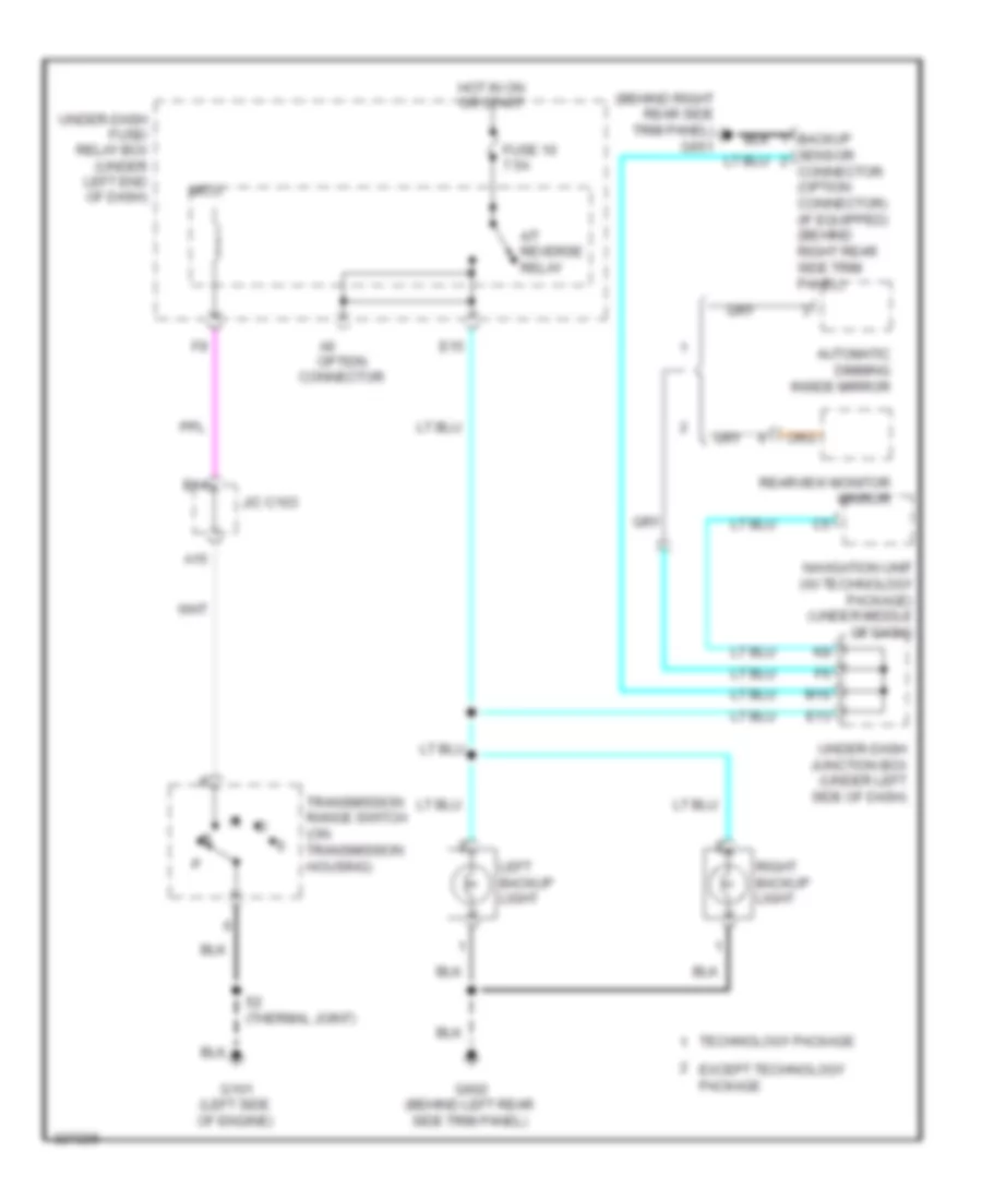
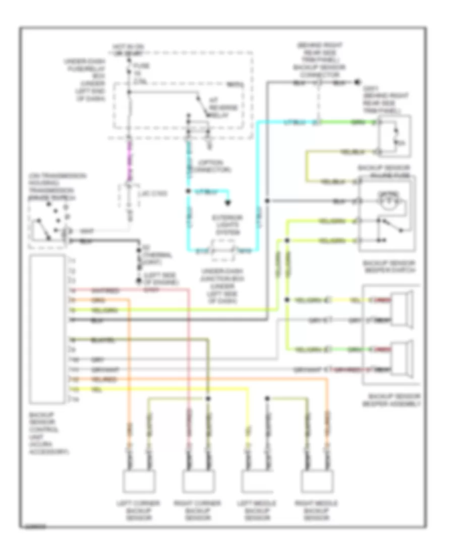
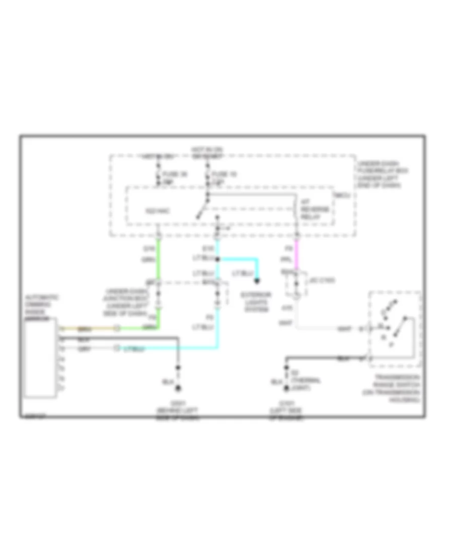
Backup Lamps Wiring Diagram for Acura RDX 2010
List of elements for Backup Lamps Wiring Diagram for Acura RDX 2010:
- (behind right rear side trim panel) g651
- A/t reverse relay
- A15
- A6 option connector
- Automatic dimming inside mirror
- B14
- Backup sensor connector (option connector) (if equipped) (behind right rear side trim panel)
- E13
- E15
- Except technology package
- Fuse 10 7.5a
- G101 (left side of engine)
- G602 (behind left rear side trim panel)
- Hot in on or start
- J/c c103
- Left backup light
- M10
- Micu
- Navigation unit (w/ technology package) (under middle of dash)
- Rearview monitor mirror
- Right backup light
- S2 (thermal joint)
- Technology package
- Transmission range switch (on transmission housing)
- Under-dash fuse/ relay box (under left end of dash)
- Under-dash junction box (under left side of dash)
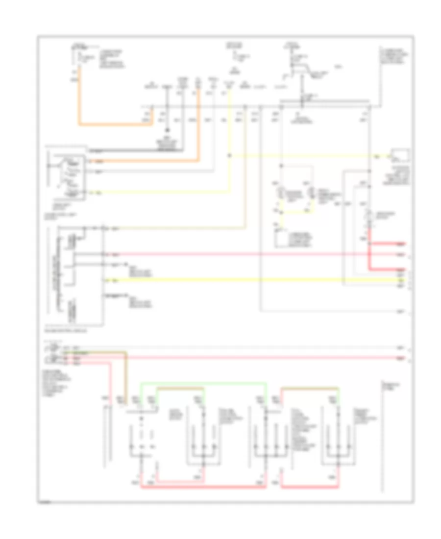
Exterior Lamps Wiring Diagram (1 of 2) for Acura RDX 2010
List of elements for Exterior Lamps Wiring Diagram (1 of 2) for Acura RDX 2010:
- (not used)
- +b backup
- B-can
- Brake pedal position switch (under left side of dash)
- Computer data lines system
- E19
- E34
- F30
- F31
- Fuse 12 15a
- Fuse 15 15a
- Fuse 19 20a
- Fuse 23 10a
- G16
- G201 (left front of engine compt)
- G301 (behind right side of front bumper)
- G601 (behind left rear side trim panel)
- G602 (behind left rear side trim panel)
- G651 (behind right rear side trim panel)
- Haz sw
- Hazard warning switch
- Hazard warning switch light
- High mount brake light
- Hot at all times
- Interior lights system
- Left brake light/ taillight
- Left front side marker light
- Left front turn signal/ parking light
- Left inner taillight
- Left license plate light
- Left rear side marker light
- Micu
- Pnk
- Q11
- Red
- Right brake light/ taillight
- Right front side marker light
- Right front turn signal/ parking light
- Right inner taillight
- Right license plate light
- Right rear side marker light
- S-gnd
- Stop sw
- Taillight relay
- Under-dash fuse/relay box (under left end of dash)
- Under-hood fuse/relay box (left rear of engine compt)
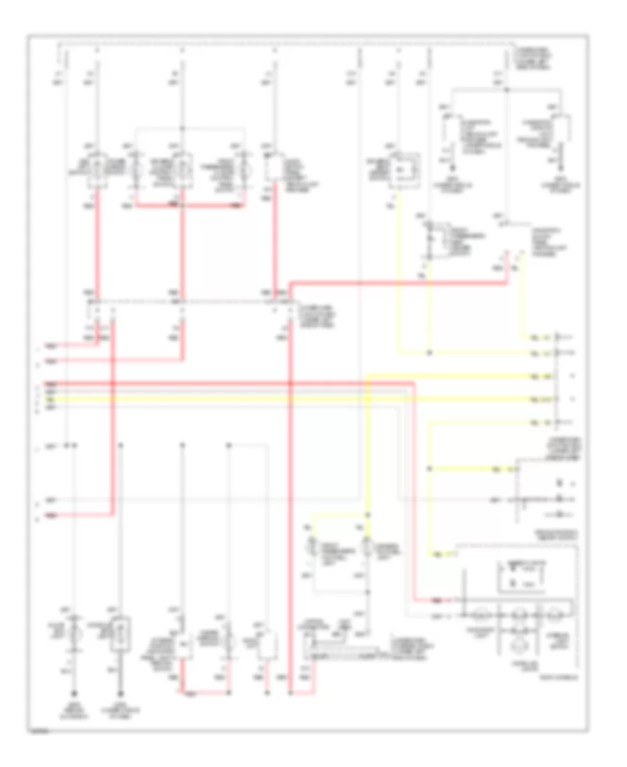
Exterior Lamps Wiring Diagram (2 of 2) for Acura RDX 2010
List of elements for Exterior Lamps Wiring Diagram (2 of 2) for Acura RDX 2010:
- (not used)
- 5v stabilize circuit/controller
- 7.5a
- Area network controller
- Auto
- Automatic lighting control unit
- B/u
- Combi gnd (light)
- Combination light switch
- E39
- E40
- Fuse 10 7.5a
- Fuse 15a
- G501 (behind left side of dash)
- G505 (behind glove box)
- G602 (behind left rear side trim panel)
- G651 (behind right rear side trim panel)
- Gauge control module
- H/l off sw
- H/l on sw
- Head
- Headlight switch
- Hot at all times
- Hot in on or start
- Ig1 meter
- Left
- Left power mirror
- Left rear turn signal light
- Left side turn signal light
- Left turn signal ind
- Micu
- Off
- Off park
- P10
- Park auto
- Red
- Right
- Right power mirror
- Right rear turn signal light
- Right side turn signal light
- Right turn signal ind
- S11
- S13
- S18
- S19
- Small lt sw
- Trailer hitch connector (acura accessory)
- Trailer lighting connector (acura accessory) (under right side of cargo area)
- Trailer lighting control unit (acura accessory)
- Trailer lighting in-line fuse 1
- Trailer lighting in-line fuse 2
- Turn left sw
- Turn right sw
- Turn signal switch
- Turn signal/hazard flasher circuit
- Turn signal/hazard relay 2 (sounder)
- Under-dash fuse/relay box (under left end of dash)
- Under-dash junction box (under left side of dash)
- Under-hood fuse/relay box (left rear of engine compt)
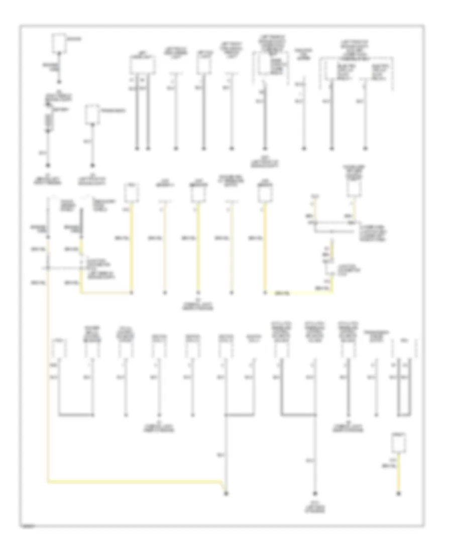
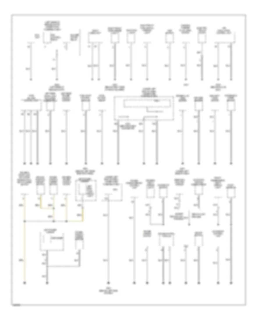
GROUND DISTRIBUTION
Ground Distribution Wiring Diagram (1 of 4) for Acura RDX 2010
List of elements for Ground Distribution Wiring Diagram (1 of 4) for Acura RDX 2010:
- (left front of engine compt) auxiliary under-hood fuse/relay box
- (left rear of engine compt) under-hood fuse/relay box
- A/t clutch pressure control solenoid valve a
- A/t clutch pressure control solenoid valve b
- A/t clutch pressure control solenoid valve c
- A12
- B12
- B36
- Battery
- Braided wire
- C40
- C44
- Ckp sensor
- Cmp sensor a
- Cmp sensor b
- Dlc
- Electric vacuum pump relay 1
- Electric vacuum pump relay 2
- Engine
- G1 (behind left front fender)
- G101 (left side of engine)
- G2 (right side of engine compt)
- G201 (left front of engine compt)
- G3 (left front of engine compt)
- Ignition coil 1
- Ignition coil 2
- Ignition coil 3
- Ignition coil 4
- Immobilizer keyless control unit
- Junction connector c103
- Junction connector c104 (left rear of engine compt)
- Knock sensor shield
- Left fog light
- Left front side marker light
- Left front turn signal/ parking light
- Left headlight
- Pcm
- Radiator fan motor
- Rear window wiper relay
- Rocker arm oil control solenoid
- Rocker arm oil pressure switch
- S1 (thermal joint) (rear of engine)
- S2 (thermal joint) (rear of engine)
- S4 (thermal joint) (rear of engine)
- Secondary ho2s shield
- Transmission
- Transmission range switch
- Under-dash junction box (under left side of dash)
- Vtc oil control solenoid valve
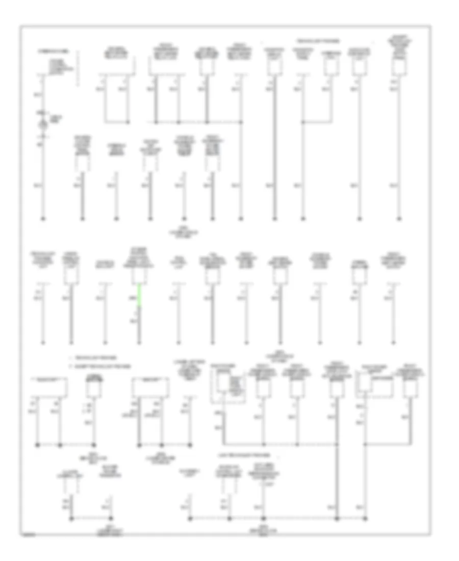
Ground Distribution Wiring Diagram (2 of 4) for Acura RDX 2010
List of elements for Ground Distribution Wiring Diagram (2 of 4) for Acura RDX 2010:
- (4wd) sh-awd control unit
- (4wd) sh-awd relay
- (canada) washer fluid level switch
- (left rear of engine compt) under-hood fuse/relay box
- (under left end of dash) under-dash fuse/relay box
- Automatic dimming inside mirror
- Blower motor relay
- Brake fluid level switch
- Defogger
- Dlc
- Driver's door lock actuator/ knob switch/ key cylinder switch
- Driver's power window motor
- Driver's vanity mirror light
- Driving position memory switch
- E33
- Eld unit
- Electric vacuum pump
- Except technology package
- F20
- Fan control relay
- Front passenger's vanity mirror light
- Fuel pump control module
- G202 (left rear of engine compt)
- G301 (behind right side of front bumper)
- G401
- G402 (behind glove box)
- G451 (under left side of dash)
- G501 (behind left side of dash)
- G601 (behind left rear side trim panel)
- Gauge control module
- Keyless buzzer
- Left power mirror
- Left rear door lock actuator/ knob switch
- Left rear power window switch
- Left side turn signal light
- Micu
- Micu service check connector
- Moonroof control unit
- Moonroof switch
- Power mirror memory control unit
- Power mirror switch
- Power window master switch
- Psp switch
- Rearview monitor mirror
- Right fog light
- Right front side marker light
- Right front turn signal/ parking light
- Right headlight
- Roof console
- Security hood switch
- T34
- Technology package
- Vsa modulator control unit
- Vsa off switch
- Windshield wiper motor
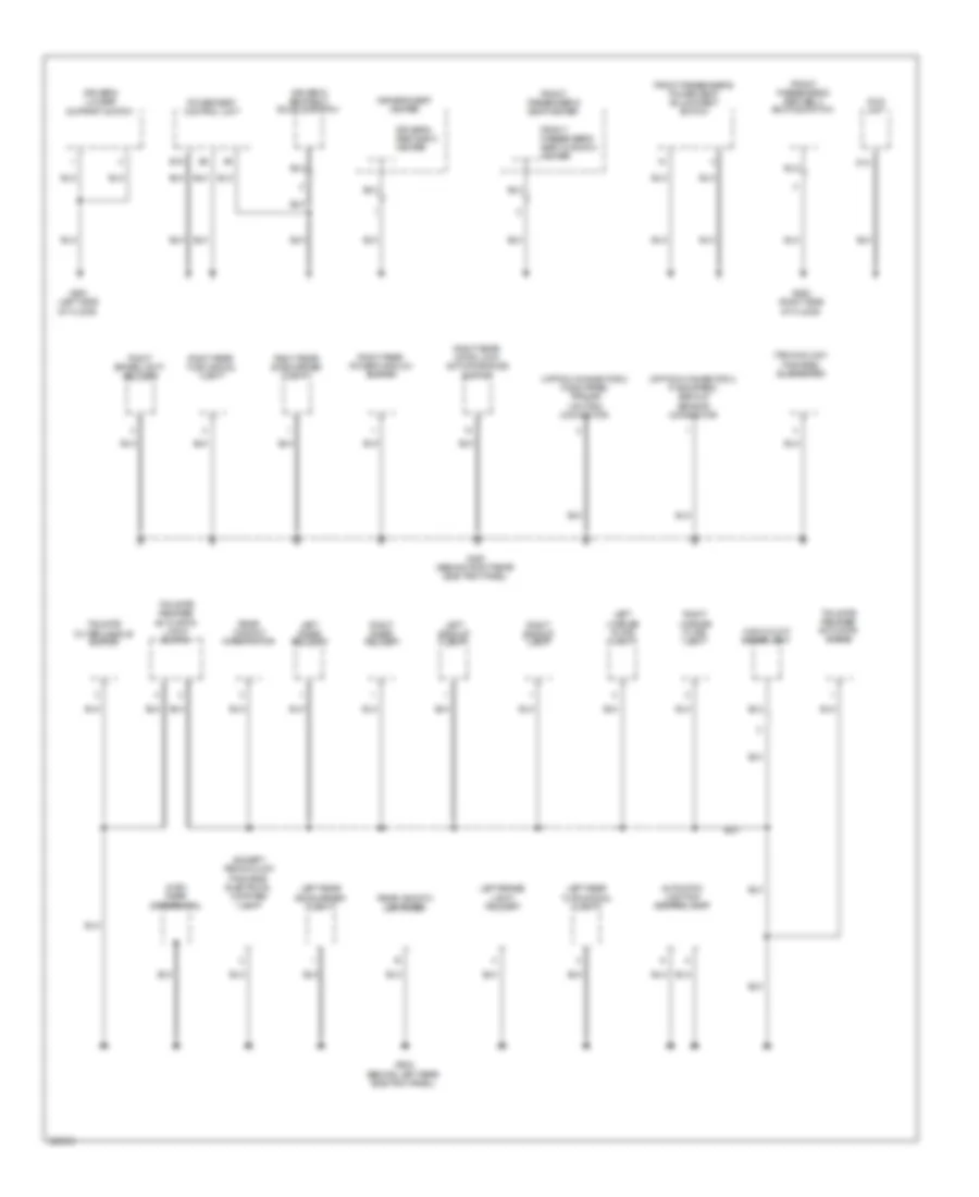
Ground Distribution Wiring Diagram (3 of 4) for Acura RDX 2010
List of elements for Ground Distribution Wiring Diagram (3 of 4) for Acura RDX 2010:
- (except technology package) audio switch panel
- (not used) acuralink reprogramming connector
- (technology package)
- (technology package) navigation unit
- (under left end of dash) under-dash fuse/relay box
- (usa: technology package)
- A/t gear position indicator panel light/ park pin switch
- A10
- A11
- A22
- A23
- A24
- Acuralink control unit (xm receiver)
- Audio unit
- Audio-hvac sub-display unit
- Blower power transistor
- C307
- Cable reel
- Climate control unit
- Console accessory power socket
- Console accessory power socket relay
- Console box light
- Cruise control combination switch
- Defogger
- Driver's climate control panel switch
- Driver's seat heater relay (high)
- Driver's seat heater relay (low)
- Driver's seat heater switch
- Except technology package
- Front accessory power socket
- Front accessory power socket relay
- Front passenger's door lock actuator/knob switch
- Front passenger's power window motor
- Front passenger's power window switch
- Front passenger's seat heater relay (high)
- Front passenger's seat heater relay (low)
- Front passenger's seat heater switch
- G502 (under middle of dash)
- G503 (under middle of dash)
- G504 (behind glove box)
- G505 (behind glove box)
- G506 (under center console)
- G571 (under right side of dash)
- Glove box light
- Hands- freelink control unit
- Ignition key switch/key light
- Interface dial
- Navigation display unit
- Navigation switch panel
- Right power mirror
- Right side turn signal light
- Srs unit
- Steering angle sensor
- Steering wheel
- Stereo amplifier
- Technology package
- Tpms control unit
- Yaw rate-lateral acceleration sensor
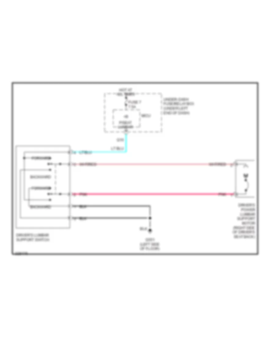
Ground Distribution Wiring Diagram (4 of 4) for Acura RDX 2010
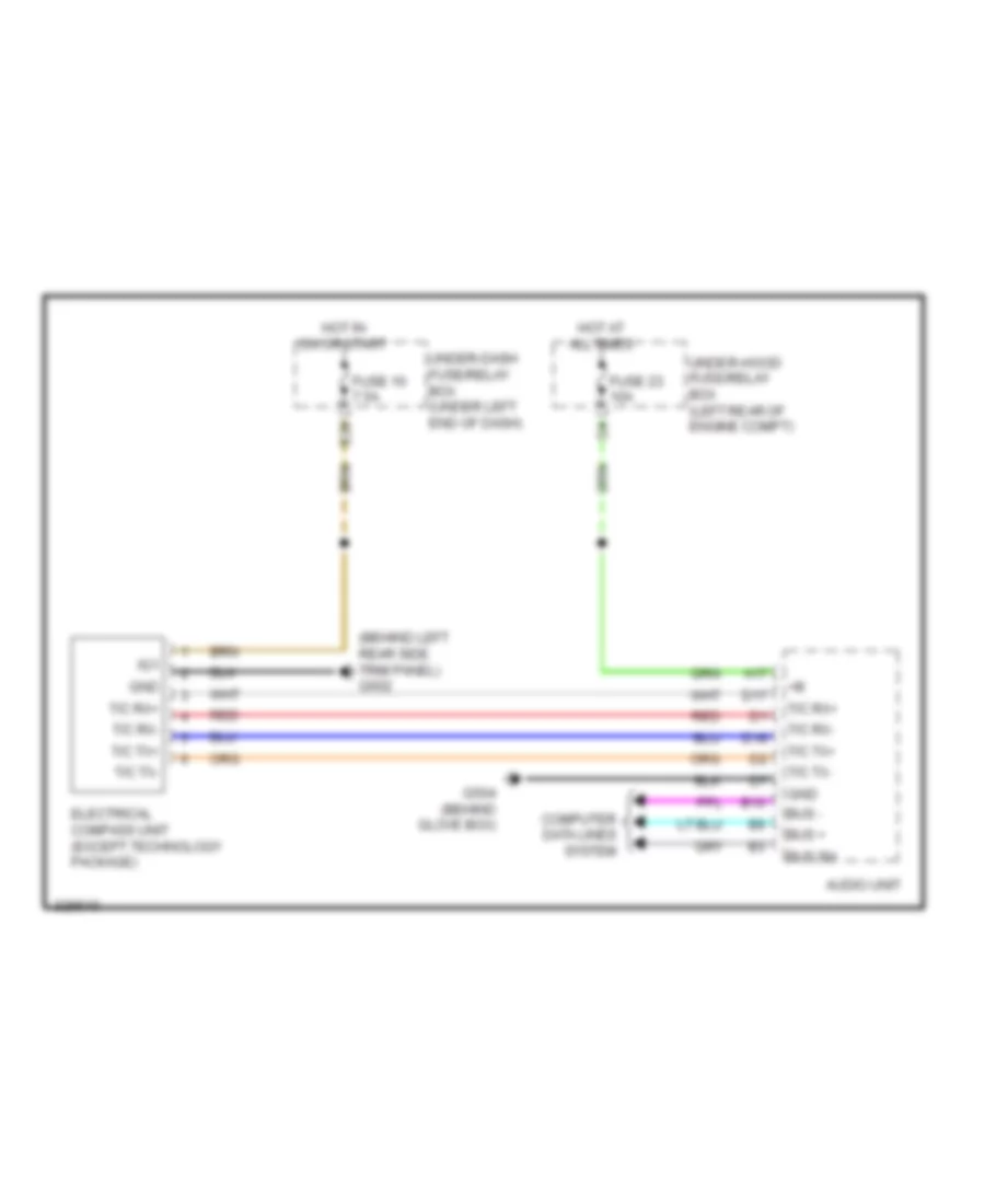
List of elements for Ground Distribution Wiring Diagram (4 of 4) for Acura RDX 2010:
- (4wd) rear differential
- (except technology package) electrical compass unit
- (option connector 2 if equipped) backup sensor connector
- (option connector 2 if equipped) trailer lighting connector
- (technology package) subwoofer
- Automatic lighting control unit
- B18
- D12
- Driver's lumbar support switch
- Driver's seat back heater
- Driver's seat belt buckle switch
- Driver's seat heater
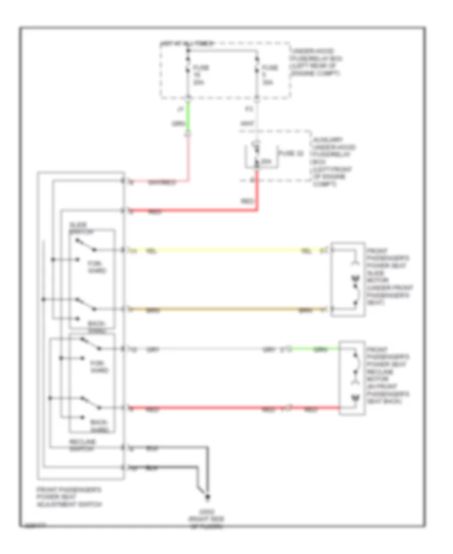
- Front passenger's power seat adjustment switch
- Front passenger's seat belt buckle switch
- Front passenger's seat cushion heater
- Front passenger's seat heater
- G551 (left side of floor)
- G552 (right side of floor)
- G602 (behind left rear side trim panel)
- G651 (behind right rear side trim panel)
- High mount brake light
- Left backup light
- Left brake light/ taillight
- Left inner taillight
- Left license plate light
- Left rear side marker light
- Left rear turn signal light
- Ods unit
- Power seat control unit
- Rear window defogger
- Rear window wiper motor
- Right backup light
- Right brake light/ taillight
- Right inner taillight
- Right license plate light
- Right rear door lock actuator/knob switch
- Right rear power window switch
- Right rear side marker light
- Right rear turn signal light
- Tailgate outer handle switch
- Tailgate release actuator diode
- Tailgate release actuator/ latch switch
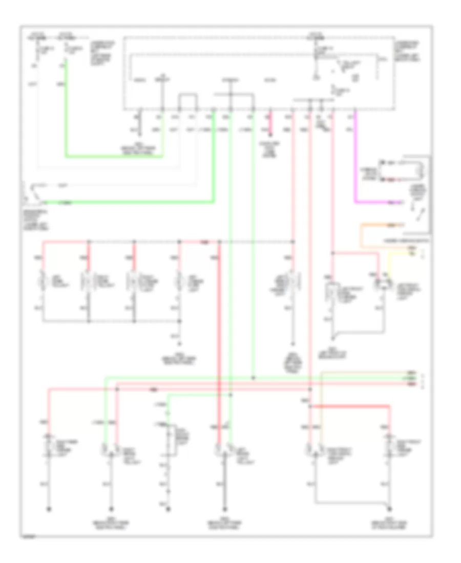
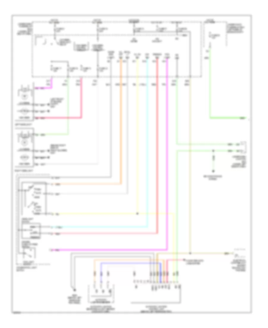
HEADLIGHTS
Headlights Wiring Diagram (1 of 2) for Acura RDX 2010
List of elements for Headlights Wiring Diagram (1 of 2) for Acura RDX 2010:
- (behind right side of front bumper) g301
- (left front of engine compt) g201
- (light)
- Air conditioning system
- Auto
- Automatic lighting control unit (behind left rear side trim)
- Automatic lighting sensor
- Automatic lighting sensor/sunlight sensor (middle of dash)
- B/u
- Bus
- Combi gnd
- Combination light switch
- Computer data lines system
- Dim
- Dimmer/ flash-to-pass switch
- E28
- Electrical compass unit (except technology package)
- F22
- Fog
- Fog light switch
- Fuse 10 7.5a
- Fuse 12 10a
- Fuse 13 10a
- Fuse 16 15a
- Fuse 17 15a
- Fuse 18 20a
- Fuse 21 30a
- Fuse 23 10a
- Fuse 36 10a
- Fuse 37 7.5a
- G15
- G17
- G602 (behind left rear side trim panel)
- Gnd1
- Gnd2
- H/l off
- H/l on
- Hac
- Head
- Headlight switch
- Hid unit
- High
- High beam
- High beam control circuit
- Hot at all times
- Hot in on
- Hot in on or start
- Ig1
- Ig1 meter
- Ig2
- Ig2 daylight
- J22
- Left headlight
- Low
- Low beam
- Low beam headlight relay
- Lt sw
- Micu
- Off
- Park
- Passing
- Pnk
- Q16
- Red
- Right headlight
- S11
- S12
- S13
- S14
- S16
- Sig
- Sio
- Sip
- Small lt
- Under-dash fuse/relay box (under left end of dash)
- Under-dash junction box (under left side of dash)
- Under-hood fuse/relay box (left rear of engine compt)
Headlights Wiring Diagram (2 of 2) for Acura RDX 2010
List of elements for Headlights Wiring Diagram (2 of 2) for Acura RDX 2010:
- +b backup
- 5v stabilize circuit/controller area network controller
- B-can
- Body controller area network transceiver
- Computer data lines system
- Drl ind
- E33
- F20
- Fog light ind
- Fog light ind dimming circuit
- Fog light relay (under left side of dash)
- Fr fog
- Fuse 6 20a
- G201 (left front of engine compt)
- G301 (behind right side of front bumper)
- G451 (under left side of dash)
- G501 (behind left side of dash)
- G601 (behind left rear side trim panel)
- Gauge control module
- High beam dimming circuit
- High beam ind
- Hot at all times
- Ig1 meter
- Left fog light
- Lights on ind
- Micu
- Multi-information display (mid) unit
- P-gnd
- P10
- Parking brake check circuit
- Parking brake switch (at base of parking brake lever)
- Pnk
- Power distribution system
- Right fog light
- Rly cl-
- S-gnd
- S-gnd2
- Small light dimming circuit
- T34
- Under-dash fuse/relay box (under left end of dash)
- Warning driver circuit
HORN
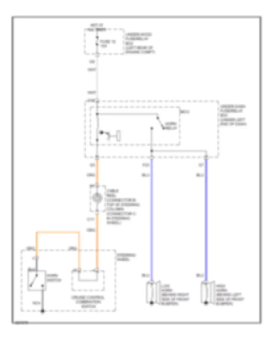
Horn Wiring Diagram for Acura RDX 2010
List of elements for Horn Wiring Diagram for Acura RDX 2010:
- C11
- Cable reel (connector b: top of steering column) (connector c: in steering wheel)
- Cruise control combination switch
- F23
- Fuse 12 15a
- G16
- High horn (behind left side of front bumper)
- Horn relay
- Horn switch
- Hot at all times
- Low horn (behind right side of front bumper)
- Micu
- Nca
- Steering wheel
- Under-dash fuse/relay box (under left end of dash)
- Under-hood fuse/relay box (left rear of engine compt)
INSTRUMENT CLUSTER
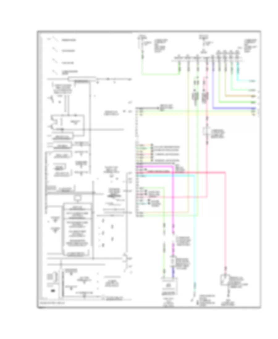
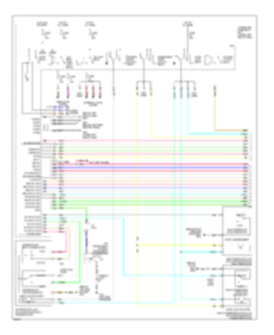
Instrument Cluster Wiring Diagram (1 of 2) for Acura RDX 2010
List of elements for Instrument Cluster Wiring Diagram (1 of 2) for Acura RDX 2010:
- (behind left side of dash) g501
- 5v stabilize circuit/controller area network controller
- A/t gear position dimming circuit
- A/t gear position ind drive circuit
- A/t temperature ind
- Anti-lock brakes system
- B-can
- Backup
- Brake fluid check circuit
- Brake fluid level switch (on brake master cylinder reservoir)
- Buzzer
- C13
- C14
- Computer data lines system
- Cruise control system
- Data lines computer
- Dial brightness control & dimming circuit
- Distribution system
- Door & tailgate open monitor
- Driver circuit
- E12
- E17
- E36
- E37
- Eeprom
- Exterior lights system
- Fog light ind
- Fog light ind dimming circuit
- Fr door sw (as)
- Fr door sw (dr)
- Fuel gauge
- Fuel gauge sending unit
- Fuel tank unit (in top of fuel tank)
- Fuse 10 7.5a
- Fuse 23 10a
- G451 (under left side of dash)
- G501 (behind left side of dash)
- Gauge control module
- High beam dimming circuit
- High beam ind
- Hot at all times
- Hot in on or start
- Ig1
- Illumination volume
- Immobilizer system ind
- Interior lights system
- J19
- Lcd back light
- Lights on ind
- Low tire pressure ind
- Meter
- Multi-information display (mid) unit
- Odometer/ trip meter/ select/ reset switch
- Odometer/trip brightness control & dimming circuit
- P10
- Parking brake switch (at base of parking brake lever)
- Pnk
- Pointer brightness control & dimming circuit
- Power
- Red
- Rr door sw (as)
- Rr door sw (dr)
- Secondary fuel gauge sending unit (right rear of floor)
- Security ind
- Security ind blinking circuit
- Sh-awd ind
- Shift ind brightness control & dimming circuit
- Shift ind driver circuit
- Side air bag cut-off ind
- Small light dimming circuit
- Speedometer
- System
- T/g sw
- Tachometer
- To left turn signal ind (diagram 2 of 2)
- To low fuel ind (diagram 2 of 2)
- Turbo booster meter
- Under-dash fuse/relay box (under left micu end of dash)
- Under-dash junction box (under left side of dash)
- Under-hood fuse/relay box (left rear of engine compt)
- Warning driver circuit
- Wiper/washer system
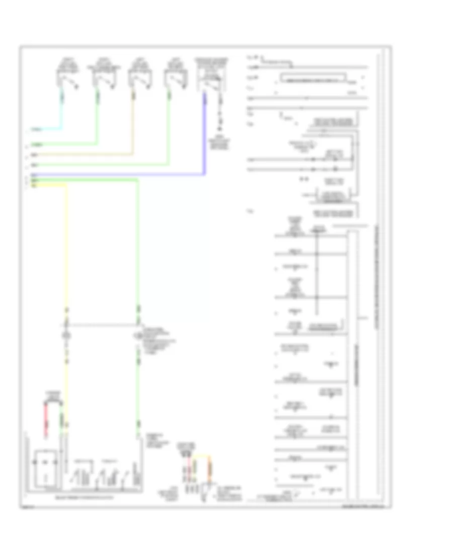
Instrument Cluster Wiring Diagram (2 of 2) for Acura RDX 2010
List of elements for Instrument Cluster Wiring Diagram (2 of 2) for Acura RDX 2010:
- (canada) washer fluid level ind
- (canada: amber) (usa) brake system ind
- (canada: red) (usa) brake system ind
- (left b-pillar) driver's door switch
- (left c-pillar) left rear door switch
- (middle of tailgate) tailgate release actuator/ latch switch
- (right b-pillar) front passenger's door switch
- (right c-pillar) right rear door switch
- 1 of 2)
- 5v stabilize circuit/controller area network controller
- A36
- A37
- Abs ind
- Active circuit
- B14
- B15
- Body controller area network transceiver
- C14
- C15
- Cable reel (connector b: top of steering column) (connector c: in steering wheel)
- Canh
- Canl
- Charging system ind
- Computer data lines system
- Cruise control dimming circuit
- Cruise control ind
- Cruise control main switch ind
- Drl ind
- Fast controller area network transceiver
- From a/t temperature ind (diagram 1 of 2)
- From pin 19 (diagram b
- G602 (behind left rear side trim panel)
- Gauge control module
- Information ind
- Interior lights system
- Left turn signal ind
- Low fuel ind
- Low oil pressure ind
- Maintenance required ind
- Mil ind
- Oil pressure switch (right side of engine compt)
- Parking brake check circuit
- Pcm (left front of engine compt)
- Red
- Right turn signal ind
- Seat belt reminder ind
- Select/reset/information switch
- Srs ind
- Steering wheel (technology package)
- Sw in
- Switch next
- Switch select/reset
- Tailgate latch switch
- Tpms ind
- Turn signal/ hazard relay 2 (sounder)
- Vsa activation ind
- Vsa system ind
- Warning driver circuit
INTERIOR LIGHTS
Courtesy Lamps Wiring Diagram for Acura RDX 2010
List of elements for Courtesy Lamps Wiring Diagram for Acura RDX 2010:
- (as)
- Ambient lights
- Auto
- Cargo area light
- Ceiling light
- Courtesy
- Door
- Driver's door courtesy light
- Driver's door switch (left b-pillar)
- Driver's vanity mirror light
- E16
- E17
- E36
- E37
- E38
- Fr door sw
- Fr door sw (dr)
- Front individual map lights
- Front passenger's door courtesy light
- Front passenger's door switch (right b-pillar)
- Front passenger's vanity mirror light
- Fuse 22 7.5a
- G501 (behind left side of dash)
- G602 (behind left rear side trim panel)
- Home link lights
- Hot at all times
- Instrument illumination circuit
- Interior light switch
- Intr
- Left
- Left rear door switch (left c-pillar)
- Lt-
- Microphone
- Moonroof light
- Navigation system
- Off
- Pnk
- Red
- Right
- Right rear door switch (right c-pillar)
- Roof console
- Rr door sw
- Rr door sw (dr)
- T/g
- T10
- Tailgate latch switch
- Tailgate release actuator/ latch switch
- Trunk
- Under-dash fuse/relay box (under left end of dash)
- Under-dash junction box (under left side of dash)
- Under-dash micu fuse/relay box (under left end of dash)
- Under-hood fuse/relay box (left rear of engine compt)
Entry Light Timer Wiring Diagram for Acura RDX 2010
List of elements for Entry Light Timer Wiring Diagram for Acura RDX 2010:
- (not used)
- +b backup
- Anti-theft system
- Auto
- B-can
- Ceiling light
- Computer data lines system
- Door
- Door lock knob
- Driver's door lock actuator/ knob switch/ key cylinder switch (except key cylinder switch: driver's door)
- Driver's door lock knob switch
- Driver's door switch (left b-pillar)
- E17
- E37
- Fr door sw (as)
- Fr door sw (dr)
- Front individual map lights
- Front passenger's door switch (right b-pillar)
- Fuse 10 7.5a
- Fuse 22 7.5a
- Fuse 23 10a
- G501 (behind left side of dash)
- G502 (under middle of dash)
- G601 (behind left rear side trim panel)
- Hot at all times
- Hot in on or start
- Ig1
- Ignition key switch
- Ignition key switch/ key light
- Interior light switch
- Intr lt-
- Key
- Key sw
- Left
- Left rear door switch (left c-pillar)
- Meter
- Micu
- Off
- Pnk
- R16
- Right
- Right rear door switch (right c-pillar)
- Roof console
- Rr door sw (as)
- Rr door sw (dr)
- S-gnd
- T23 sil dr unlock
- T24 sil dr lock
- Under-dash fuse/relay box (under left end of dash)
- Under-dash junction box (under left side of dash)
- Under-hood fuse/relay box (left rear of engine compt)
Instrument Illumination Wiring Diagram (1 of 2) for Acura RDX 2010
List of elements for Instrument Illumination Wiring Diagram (1 of 2) for Acura RDX 2010:
- (light)
- (option connector)
- +b backup
- Audio remote switch
- Auto
- Automatic lighting control unit (behind left rear side trim)
- B/u
- B10
- Cable reel (connector b: top of steering column) (connector c: in steering wheel)
- Combi gnd
- Combination light switch
- Controller area network controller 5v stabilize circuit/
- Cruise control combination switch
- Driver's footwell light
- E25
- Front passenger's footwell light
- Fuse 10 7.5a
- Fuse 14 7.5a
- Fuse 19 20a
- Fuse 23 10a
- G501 (behind left side of dash)
- G601 (behind left rear side trim panel)
- Gauge control module
- H/l off
- H/l on
- Head
- Headlight switch
- Hfl- voice control switch (technology package) hfl- switch (except technology package)
- Hot at all times
- Hot in on or start
- Ig1
- Ig1 meter
- Illumi +
- Meter
- Micu
- Moonroof switch
- Off
- P10
- Park
- Q12
- Red
- S-gnd
- S11
- S13
- Select/ reset/ information switch
- Small lt
- Steering wheel
- Taillight relay
- Under-dash fuse/relay box (under left end of dash)
- Under-dash junction box (under left side of dash)
- Under-hood fuse/relay box (left rear of engine compt)
- Volume illumination
Instrument Illumination Wiring Diagram (2 of 2) for Acura RDX 2010
List of elements for Instrument Illumination Wiring Diagram (2 of 2) for Acura RDX 2010:
- (not used)
- (option connector)
- A/t gear position indicator panel light/ park pin switch
- A10
- A18
- A20
- Ambient lights
- Audio switch panel (except technology package)
- Audio unit
- C10
- C11
- C12
- Console box light
- Driver's climate control panel switch
- Driver's footwell light
- Driver's seat heater switch
- Driving position memory switch
- E25
- E26
- F10
- Front passenger's climate control panel switch
- Front passenger's footwell light
- Front passenger's seat heater switch
- G502 (under middle of dash)
- G503 (under middle of dash)
- G505 (behind glove box)
- Glove box light
- Hazard warning switch
- Home link lights
- Illum+
- Illum-
- Interior light switch
- J11
- K11
- Micu
- Moonroof light
- Navigation display unit (technology package)
- Navigation switch panel (technology package)
- Navigation unit (technology package) (under middle of dash)
- Power mirror switch
- Q13
- Red
- Roof console
- Under-dash fuse/relay box (under left end of dash)
- Under-dash junction box (under left side of dash)
- Vsa off switch
MEMORY SYSTEMS
Memory Mirrors Wiring Diagram (1 of 2) for Acura RDX 2010
List of elements for Memory Mirrors Wiring Diagram (1 of 2) for Acura RDX 2010:
- (behind left side of dash) g501
- (under left side of dash) under-dash junction box
- +b backup
- Air conditioning system
- Defogger
- Defogger system
- Exterior lights system
- Fuse 1 7.5a
- Fuse 23 10a
- Fuse 36 10a
- G10
- Hot at all times
- Hot in on
- Hot in on or start
- Ig1
- Ig1 4wd
- Ig2 hac
- J22
- Left power mirror (driver's door)
- Left side turn signal light
- Left/ right motor
- Lmc
- Lmh
- Lmv
- Lseh
- Lsev
- Micu
- Mldl
- Mldr
- Mrdl
- Mrdr
- Mul
- Pnk
- Power mirror memory control unit (under left side of dash)
- Q16
- R18
- Red
- Right power mirror (front passenger's door)
- Right side turn signal light
- Rmc
- Rmh
- Rmv
- Rseh
- Rsev
- Sen com
- Sen feed
- Sgnd
- Sound systems
- Swing
- Tilt
- Uart bus
- Under- hood fuse/ relay box (left rear of engine compt)
- Under-dash fuse/relay box (under left end of dash)
- Under-dash junction box (under left side of dash)
- Up/ down motor
Memory Mirrors Wiring Diagram (2 of 2) for Acura RDX 2010
List of elements for Memory Mirrors Wiring Diagram (2 of 2) for Acura RDX 2010:
- (behind left side of dash) g501
- B-can
- Computer data lines system
- Down
- Driving position memory switch
- E10
- Fuse 20a
- G501 (behind left side of dash)
- G551 (left side of floor)
- Gauge control module
- Hot at all times
- Ig1
- Interior lights system
- Left
- Mem ind1
- Mem ind2
- Mem pos1
- Mem pos2
- Mem set
- Memo button
- Mirror selection switch
- Pnk
- Position 1 button
- Position 1 ind
- Position 2 button
- Position 2 ind
- Power mirror switch
- Power mirror switch light
- Power seat control unit (underside of driver's seat)
- Red
- Right
- Switch 1
- Switch 2
- Switch 3
- Uart
- Under-hood fuse/relay box (left rear of engine compt)
- Vmp2
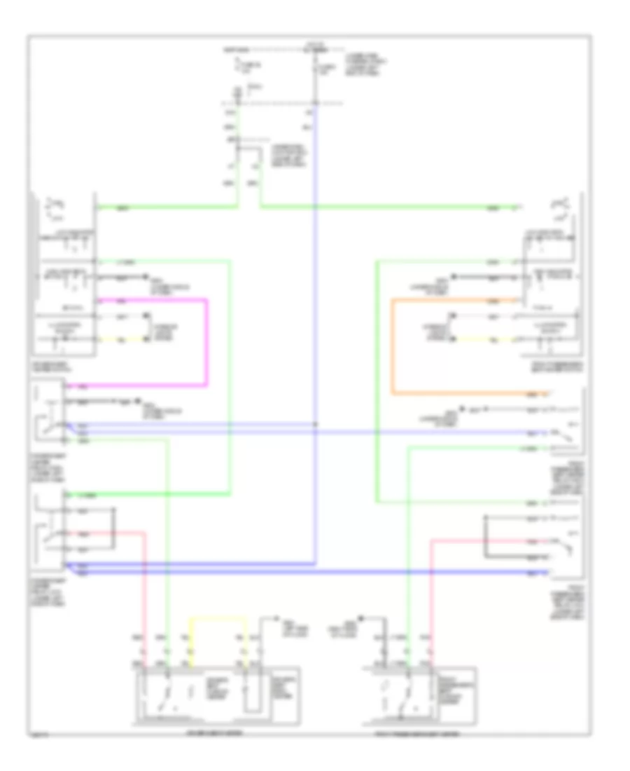
Memory Seat Wiring Diagram (1 of 2) for Acura RDX 2010
List of elements for Memory Seat Wiring Diagram (1 of 2) for Acura RDX 2010:
- (left side of floor) g551
- Atp-p
- B-can
- Computer data lines system
- Driver's power seat front up-down motor/positon sensor (right side of driver's seat)
- Driver's power seat rear up-down motor/positon sensor (left side of driver's seat)
- Driver's power seat recline motor/positon sensor (in driver's seat)
- Driver's power seat slide motor/ position sensor (under driver's seat)
- E10
- Fhdn
- Fhm +
- Fhm -
- Fhse
- Fhup
- Fuse 10a
- Fuse 20a
- G551 (left side of floor)
- Gnd
- Hot at all times
- Ig1
- Memind1
- Memind2
- Mempos1
- Mempos2
- Memset
- Pnk
- Power seat control unit (underside of driver's seat)
- Red
- Refw
- Rem +
- Rem -
- Rerw
- Rese
- Rhdn
- Rhm +
- Rhm -
- Rhse
- Rhup
- Scom
- Seg
- Sensor
- Slfw
- Slm +
- Slm -
- Slrw
- Slse
- Svcc
- Uart
- Under-hood fuse/relay box (left rear of engine compt)
- Vcc
- Vmp1
- Vmp2
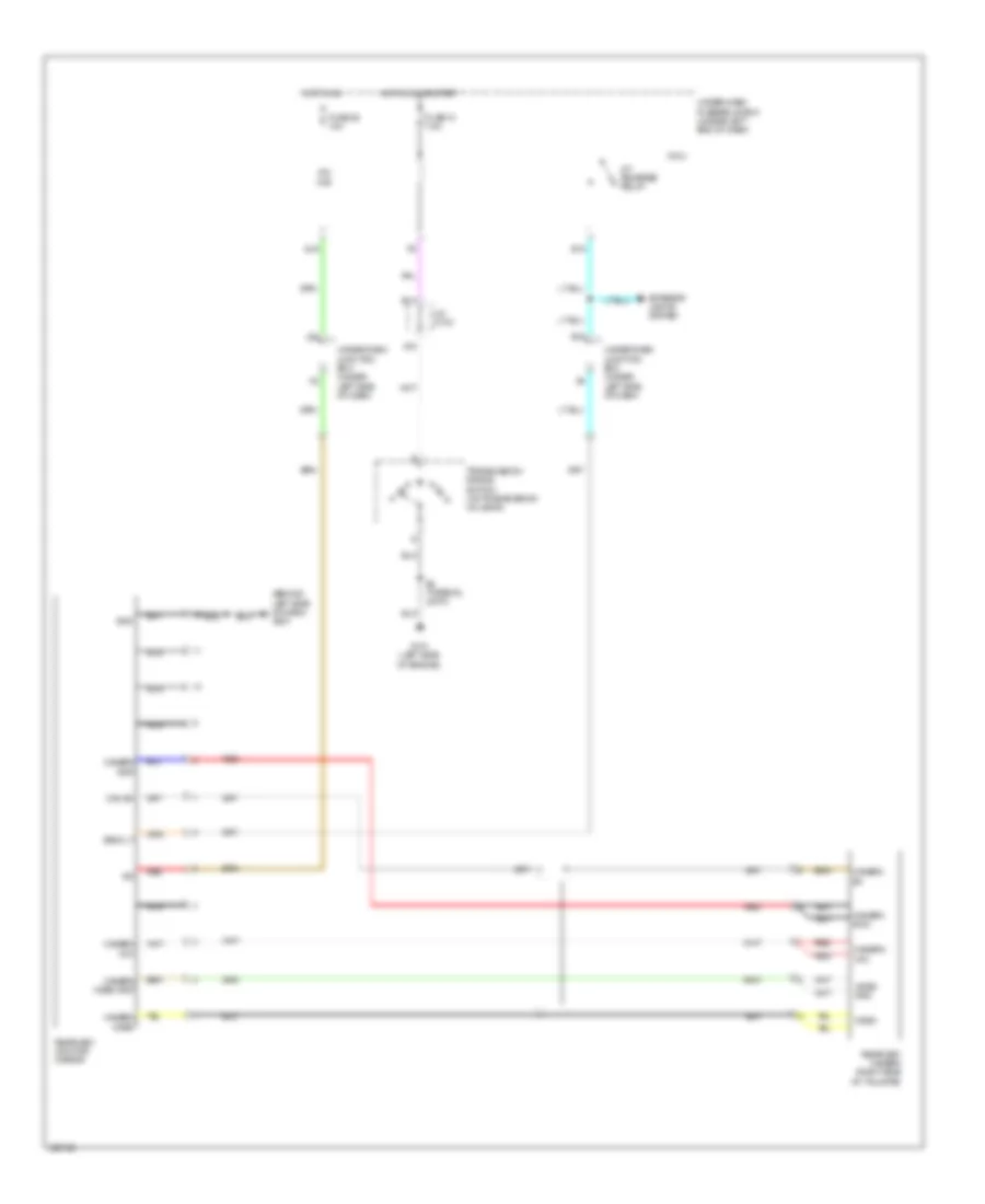
Memory Seat Wiring Diagram (2 of 2) for Acura RDX 2010
List of elements for Memory Seat Wiring Diagram (2 of 2) for Acura RDX 2010:
- (under left side of dash) power mirror memory control unit
- +b backup
- 4wd
- A17
- A22
- A23
- Atpp
- Audio unit
- B-can
- B13
- Back
- Computer data lines system
- Driver position memory switch light
- Driver's power seat adjustment switch
- Driving position memory switch
- F27
- Front up- down switch
- Fuse 1 7.5a
- Fwd
- G10
- G101 (left side of engine)
- G501 (behind left side of dash)
- Gauge control module
- Hot in on or start
- Ig1
- Interior lights system
- J/c c103
- J19
- L10
- Memo button
- Memory mirror circuit
- Micu
- Pcm (left front of engine compt)
- Pnk
- Position 1 button
- Position 1 indicator
- Position 2 button
- Position 2 indicator
- R18
- Rear up- down switch
- Recline switch
- Red
- S2 (thermal joint)
- Slide switch
- Transmission range switch (on transmission housing)
- Under dash junction box (under left side of dash)
- Under- dash fuse/ relay box (under left end of dash)
NAVIGATION
Compass Wiring Diagram for Acura RDX 2010
List of elements for Compass Wiring Diagram for Acura RDX 2010:
- (behind left rear side trim panel) g602
- A17
- Audio unit
- B10
- Bus +
- Bus -
- Bus sh
- Computer data lines system
- D17
- D18
- E28
- Electrical compass unit (except technology package)
- Fuse 10 7.5a
- Fuse 23 10a
- G504 (behind glove box)
- Gnd
- Hot at all times
- Hot in on or start
- Ig1
- Red
- T/c rx+
- T/c rx-
- T/c tx+
- T/c tx-
- Under-dash fuse/relay box (under left end of dash)
- Under-hood fuse/relay box (left rear of engine compt)
Home Link Remote Control Wiring Diagram for Acura RDX 2010
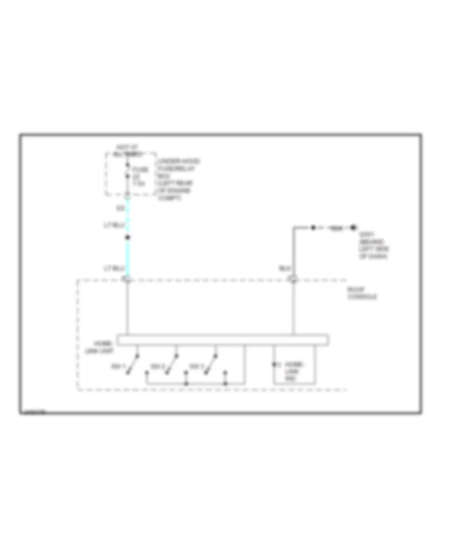
List of elements for Home Link Remote Control Wiring Diagram for Acura RDX 2010:
- Fuse 7.5a
- G501 (behind left side of dash)
- Home- link ind
- Home- link unit
- Hot at all times
- Roof console
- Sw 1
- Sw 2
- Sw 3
- Under-hood fuse/relay box (left rear of engine compt)
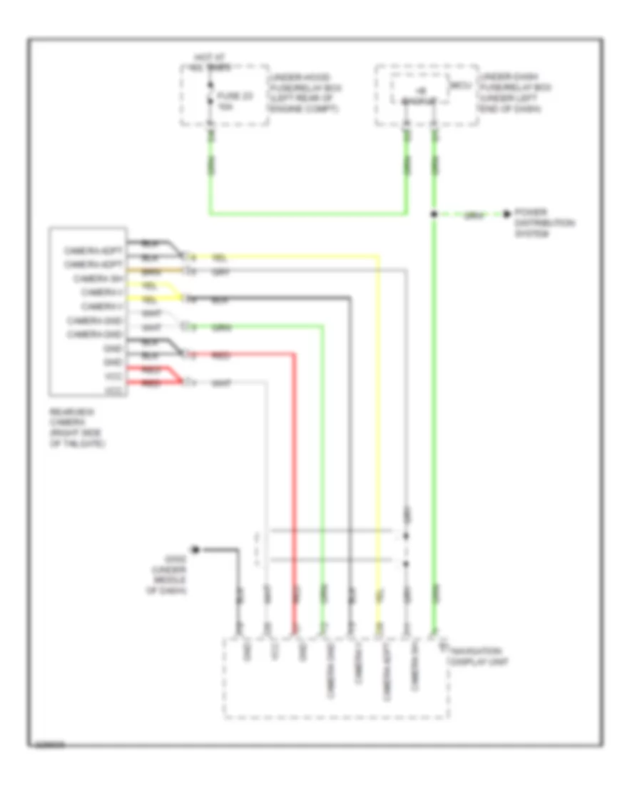
Navigation Wiring Diagram, Canada (1 of 2) for Acura RDX 2010
List of elements for Navigation Wiring Diagram, Canada (1 of 2) for Acura RDX 2010:
- (left front of engine compt) pcm
- (not used)
- (under middle of dash) g503
- (under middle of dash) navigation service check connector
- +b backup
- A/c-clk
- A/c-si
- A/c-so
- A10
- A11
- A12
- A13
- A14
- A15
- A16
- A17
- A18
- A19
- A20
- A21
- A22
- A23
- A24
- A25
- A26
- A27
- A28
- A29
- A30
- A31
- A32
- Acc
- Acc cut relay
- Acc radio
- Amplifier
- B-sig
- B10
- B11
- B12
- B13
- B14
- B15
- B16
- Back lt
- Bus +
- Bus -
- Bus sh
- C-sig
- Camera adpt
- Camera gnd
- Camera sh
- Camera v
- Can-h
- Can-l
- Climate control unit (behind glove box)
- Computer data lines system
- Diag n
- Diag p
- E15
- Ecu bus
- Ecu bus +
- Ecu bus -
- Exterior lights system
- Fuse 10a
- Fuse 7.5a
- G-sig
- G502 (under middle of dash)
- Gnd
- Gnd mic
- Gnd rg
- Gnd sig
- Gps antenna (behind left side of dash)
- Hfl comm 1
- Hfl comm 2
- Hfl comm 3
- Hfl comm 4
- Hot at all times
- Hot in acc or on
- Ill +
- Interior lights system
- J13
- J15
- J16
- Jog
- K12
- K13
- K14
- Mic out +
- Micu
- Navi-clk
- Navi-si
- Navi-so
- Navigation display unit
- Navigation unit (under middle of dash)
- Nca
- Pnk
- Power distribution system
- Q14
- R-sig
- Rear camera circuit
- Red
- Rg-l +
- Scty1
- Security +
- Security -
- Sh disp bus
- Sh ecu bus
- Sh gps
- Sh hfl comm
- Sh jog
- Sh mic
- Sh rg
- Sh sig
- Sig
- Strg sw
- Under-dash fuse/relay box (under left end of dash)
- Under-dash junction box (under left side of dash)
- Under-hood fuse/relay box (left rear of engine compt)
- Vcc
- Vsp
- Vssout
Navigation Wiring Diagram, Canada (2 of 2) for Acura RDX 2010
List of elements for Navigation Wiring Diagram, Canada (2 of 2) for Acura RDX 2010:
- (under middle of dash) g503
- Acc
- Audio remote switch
- Audio sh
- Audio unit
- B-can
- B10
- B18
- B19
- B21
- Back switch
- Bus +
- Bus -
- Bus sh
- Bus+
- Bus-
- C10
- C12
- C13
- C14
- C18
- C19
- C27
- C28
- Cable reel (con b: top of steering column) (con c: in steering wheel)
- Computer data lines system
- G502 (under middle of dash)
- Gnd
- Handsfreelink control unit (under center console)
- Hfl-voice control switch
- Hft comm 1
- Hft comm 2
- Hft comm 3
- Hft comm 4
- Hft comm sh
- Hft icon
- Hft mute
- Hft strg sw
- Ig1
- Ill +
- Ill -
- Interface dial
- Interior lights system
- Jog
- Mic out +
- Mic out -
- Mic sh
- Mic sig +
- Mic sig -
- Microphone
- Navi gnd
- Navi l ch
- Navi sh gnd
- Navigation switch panel
- Off hook switch
- On hook switch
- Pnk
- Ptt
- Red
- Remote gnd
- Roof console
- Security
- Sh jog
- Steering wheel
- Stereo amplifier (under middle of dash)
- Talk switch
- Telm sig +
- Telm sig -
- Telm sig sh
- W/ technology package
Navigation Wiring Diagram, USA (1 of 2) for Acura RDX 2010
List of elements for Navigation Wiring Diagram, USA (1 of 2) for Acura RDX 2010:
- (left front of engine compt) pcm
- (not used)
- (under middle of dash) g503
- (under middle of dash) navigation service check connector
- +b backup
- A/c-clk
- A/c-si
- A/c-so
- A10
- A11
- A12
- A13
- A14
- A15
- A16
- A17
- A18
- A19
- A20
- A21
- A22
- A23
- A24
- A25
- A26
- A27
- A28
- A29
- A30
- A31
- A32
- Acc
- Acc cut relay
- Acc radio
- Amplifier
- B-sig
- B10
- B11
- B12
- B13
- B14
- B15
- B16
- Back lt
- Bus +
- Bus -
- Bus sh
- C-sig
- Camera adpt
- Camera gnd
- Camera sh
- Camera v
- Can-h
- Can-l
- Climate control unit (behind glove box)
- Computer data lines system
- Diag n
- Diag p
- E15
- Ecu bus
- Ecu bus +
- Ecu bus -
- Exterior lights system
- Fuse 10a
- Fuse 7.5a
- G-sig
- G502 (under middle of dash)
- Gnd
- Gnd mic
- Gnd rg
- Gnd sig
- Gps antenna (behind left side of dash)
- Hip/hfl comm 1
- Hip/hfl comm 2
- Hip/hfl comm 3
- Hip/hfl comm 4
- Hot at all times
- Hot in acc or on
- Ill +
- Interior lights system
- J13
- J15
- J16
- Jog
- K12
- K13
- K14
- Mic out +
- Micu
- Navi-clk
- Navi-si
- Navi-so
- Navigation display unit
- Navigation unit (under middle of dash)
- Nca
- Pnk
- Power distribution system
- Q14
- R-sig
- Rear camera circuit
- Red
- Rg-l +
- Scty1
- Security +
- Security -
- Sh disp bus
- Sh ecu bus
- Sh gps
- Sh hip/hfl
- Sh jog
- Sh mic
- Sh rg
- Sh sig
- Sig
- Strg sw
- Under-dash fuse/relay box (under left end of dash)
- Under-dash junction box (under left side of dash)
- Under-hood fuse/relay box (left rear of engine compt)
- Vcc
- Vsp
- Vssout
Navigation Wiring Diagram, USA (2 of 2) for Acura RDX 2010
List of elements for Navigation Wiring Diagram, USA (2 of 2) for Acura RDX 2010:
- (under middle of dash) g503
- A17
- A18
- A19
- A20
- A21
- A22
- A23
- A24
- A25
- A26
- A29
- A30
- A31
- Acc
- Acuralink control unit (xm receiver) (behind glove box)
- Audio remote switch
- Audio sh
- Audio unit
- B-can
- B10
- B18
- B19
- B21
- Back switch
- Bus +
- Bus -
- Bus sh
- Bus+
- Bus-
- C10
- C12
- C13
- C14
- C18
- C19
- C27
- C28
- Cable reel (con b: top of steering column) (con c: in steering wheel)
- Computer data lines system
- G502 (under middle of dash)
- Gnd
- Handsfreelink control unit (under center console)
- Hfl-voice control switch
- Hft comm 1
- Hft comm 2
- Hft comm 3
- Hft comm 4
- Hft comm sh
- Hft icon
- Hft mute
- Hft strg sw
- Hip/navi comm 1
- Hip/navi comm 2
- Hip/navi comm 3
- Hip/navi comm 4
- Hip/navi comm sh
- Ig1
- Ill +
- Ill -
- Interface dial
- Interior lights system
- Jog
- Mic out +
- Mic out -
- Mic sh
- Mic sig +
- Mic sig -
- Microphone
- Navi comm 1
- Navi comm 2
- Navi comm 3
- Navi comm 4
- Navi comm sh
- Navi gnd
- Navi l ch
- Navi sh gnd
- Navigation switch panel
- Off hook switch
- On hook switch
- Pnk
- Ptt
- Red
- Remote gnd
- Roof console
- Security
- Sh jog
- Sig sh
- Sig+
- Sig-
- Steering wheel
- Stereo amplifier (under middle of dash)
- Talk switch
- Telm sig+
- W/ technology package
Parking Assistant Wiring Diagram for Acura RDX 2010
List of elements for Parking Assistant Wiring Diagram for Acura RDX 2010:
- (behind right rear side trim panel) backup sensor connector
- (left side of engine) g101
- (on transmission housing) transmission range switch
- (option connector)
- A/t reverse relay
- A15
- B14
- Backup sensor beeper assembly
- Backup sensor beeper switch
- Backup sensor control unit (acura accessory)
- Backup sensor in-line fuse
- E13
- E15
- Exterior lights system
- Fuse 7.5a
- G651 (behind right rear side trim panel)
- Hot in on or start
- J/c c103
- Left corner backup sensor
- Left middle backup sensor
- M10
- Micu
- Nca
- On ind
- Red
- Right corner backup sensor
- Right middle backup sensor
- S2 (thermal joint)
- Under-dash fuse/relay box (under left end of dash)
- Under-dash junction box (under left side of dash)
Rear Camera Wiring Diagram for Acura RDX 2010
List of elements for Rear Camera Wiring Diagram for Acura RDX 2010:
- +b backup
- Camera adpt
- Camera gnd
- Camera sh
- Camera v
- Fuse 23 10a
- G502 (under middle of dash)
- Gnd
- Hot at all times
- Micu
- Navigation display unit
- Power distribution system
- Rearview camera (right side of tailgate)
- Red
- Under-dash fuse/relay box (under left end of dash)
- Under-hood fuse/relay box (left rear of engine compt)
- Vcc
POWER DISTRIBUTION
Power Distribution Wiring Diagram (1 of 6) for Acura RDX 2010
List of elements for Power Distribution Wiring Diagram (1 of 6) for Acura RDX 2010:
- (left rear of engine compt) under-hood fuse/relay box
- (not used)
- +b hazard
- +b stop & horn
- 100a
- 20a
- 30a
- 40a
- 50a
- A/c compressor clutch relay
- A/c condenser fan relay
- Alternator
- Auxiliary under-hood fuse/relay box (left front of engine compt)
- Battery
- Blower motor relay
- Brake pedal position switch
- Dlc
- E10
- Eld unit
- Etcs control relay
- F13
- F31
- From fuse 8 (diagram 1 of 6)
- Front passenger's power seat adjustment switch
- Fuse 10 15a
- Fuse 12 15a
- Fuse 13 20a
- Fuse 14 20a
- Fuse 16 20a
- Fuse 19 15a
- Fuse 20 7.5a
- Fuse 21 15a
- Fuse 32 20a
- Fuse 5 30a
- Fuse 6 30a
- Fuse 7 30a
- Fuse 8 30a
- Fuse 9 40a
- G16
- Hazard warning switch
- Micu
- Multi-fuse 1
- Multi-fuse 3
- Multi-fuse 4
- Pgm-fi main relay 1
- Power seat control unit
- Radiator fan relay
- Rear window defogger relay
- Red
- Sh-awd relay (4wd)
- Starter
- Starter solenoid
- T101
- T102
- To fuse 11 (diagram 2 of 6)
- To fuse 22 (diagram 3 of 6)
- To multi-fuse 4 (diagram 1 of 6)
- To under-dash fuse/relay box (diagram 2 of 6)
- Trailer lighting connector (option connector)
- Under-dash fuse/relay box (under left end of dash)
- Under-dash junction box (under left side of dash) m5
- Under-hood fuse/relay box (left rear of engine compt)
- Vsa modulator control unit
Power Distribution Wiring Diagram (2 of 6) for Acura RDX 2010
List of elements for Power Distribution Wiring Diagram (2 of 6) for Acura RDX 2010:
- (not used)
- +b d/l
- +b h/l hi main
- +b h/l lo
- +b h/l lo main
- +b l h/l hi
- +b r h/l hi
- +b small
- +b tpms
- A/f sensor
- A21
- Auxiliary under-hood fuse/relay box (left front of engine compt)
- B16
- B17
- Electric vacuum pump relay 2
- Evap canister purge valve
- Evap canister vent shut valve
- F16
- F18
- F19
- F22
- From multi-fuse 3 b (diagram 1 of 6)
- From under-hood fuse/relay box (diagram 1 of 6)
- Front passenger's power window switch
- Fuse 11 15a
- Fuse 12 10a
- Fuse 13 10a
- Fuse 15 7.5a
- Fuse 16 15a
- Fuse 17 15a
- Fuse 18 15a
- Fuse 18 20a
- Fuse 19 20a
- Fuse 20 7.5a
- Fuse 21 30a
- Fuse 24 20a
- Fuse 25 20a
- Fuse 26 20a
- Fuse 30 20a
- G15
- G17
- G18
- G21
- Ignition coil relay
- J/c c103
- Left headlight
- Micu
- Moonroof control unit
- Pcm
- Pgm-fi sub-relay
- Pnk
- Power window master switch
- Power window relay
- Radiator fan diode
- Radiator fan relay
- Red
- Right headlight
- Tpms control unit
- Under-dash fuse/relay box (under left end of dash)
- Under-hood fuse/relay box (left rear of engine compt)
Power Distribution Wiring Diagram (3 of 6) for Acura RDX 2010
List of elements for Power Distribution Wiring Diagram (3 of 6) for Acura RDX 2010:
- (not used)
- +b backup
- +b intr lt
- A17
- A35
- A37
- Acuralink control unit (xm receiver) (usa: technology package)
- Audio unit
- B23
- C36
- Cargo area light
- Ceiling light
- Driver's door courtesy light
- Driver's vanity mirror light
- Driving position memory switch
- E14
- E38
- F24
- From fuse 21 (diagram 1 of 6)
- Front passenger's door courtesy light
- Front passenger's vanity mirror light
- Fuse 1 7.5a
- Fuse 2 20a
- Fuse 22 7.5a
- Fuse 23 10a
- G10
- G11
- Gauge control module
- Handsfreelink control unit
- Ig1 4wd
- Ig1 fuel pump
- Ignition key switch/ key light
- Immobilizer keyless control unit
- J/c c103
- K12
- Micu
- Moonroof control unit
- N12
- Navigation display unit (technology package)
- Navigation unit (technology package)
- Pcm
- Pgm-fi main relay 2
- Power mirror memory control unit
- Power seat control unit
- Power window master switch
- R10
- R11
- R12
- R18
- Roof console
- Sh-awd control unit (4wd)
- To fuse 9 (diagram 5 of 6)
- To ignition switch (diagram 4 of 6)
- To multi-fuse 2 (diagram 4 of 6)
- Under-dash fuse/relay box (under left end of dash)
- Under-dash junction box (under left side of dash)
- Under-hood fuse/relay box (left rear of engine compt)
Power Distribution Wiring Diagram (4 of 6) for Acura RDX 2010
List of elements for Power Distribution Wiring Diagram (4 of 6) for Acura RDX 2010:
- (option connector)
- +b p/seat lumbar
- 50a
- 7.5a
- 80a
- A12
- A18
- Acc
- Acc cut relay
- Auxiliary under-dash fuse holder (under left side of dash)
- Console accessory power socket
- Console accessory power socket relay (under left side of dash)
- Driver's lumbar support switch
- Driver's seat heater relay (high)
- Driver's seat heater relay (low)
- E22
- E35
- Fog light relay
- From fuse 23 (diagram 3 of 6)
- From under-dash fuse/relay box (diagram 3 of 6)
- Front accessory power socket
- Front accessory power socket relay (under left side of dash)
- Front passenger's seat heater relay (high)
- Front passenger's seat heater relay (low)
- Fuse 27 20a
- Fuse 28 15a
- Fuse 29 15a
- Fuse 31 20a
- Fuse 5 15a
- Fuse 6 20a
- Fuse 7 7.5a
- G19
- G20
- G502 (under middle of dash)
- G503 (under middle of dash)
- Ig2 cut relay
- Ignition key switch/ key light
- Ignition switch
- Lock
- Micu
- Multi- fuse 2
- Pcm
- Q10
- Q14
- Red
- Start
- Starter cut relay 1
- Starter cut relay 2
- Stereo amplifier
- Subwoofer
- Technology package
- To under-dash fuse/relay box (diagram 6 of 6)
- To under-dash junction box (diagram 6 of 6)
- Under-dash fuse/relay box (under left end of dash)
- Under-hood fuse/relay box (left rear of engine compt)
Power Distribution Wiring Diagram (5 of 6) for Acura RDX 2010
List of elements for Power Distribution Wiring Diagram (5 of 6) for Acura RDX 2010:
- (not used)
- A10
- A12
- A17
- A18
- A19
- Acuralink control unit (xm receiver) (usa: technology package)
- Alternator
- Audio switch panel (except technology package)
- Automatic lighting control unit
- B10
- Brake pedal position switch
- Cmp sensor a
- E11
- E27
- E28
- Eld unit
- Electrical compass unit
- Except technology package
- F15
- F16
- F17
- From fuse 2 (diagram 3 of 6)
- From fuse 3 (diagram 5 of 6)
- Fuse 10 7.5a
- Fuse 11 10a
- Fuse 22 (not used)
- Fuse 3 15a
- Fuse 38 30a
- Fuse 4 7.5a
- Fuse 8 10a
- Fuse 9 7.5a
- Gauge control module
- Ig1 abs
- Ig1 meter
- Ig1 ods
- Ig1 srs
- Ig1 wiper
- J/c c103
- J/c c104 (left rear of engine compt)
- J12
- K10
- Maf/iat sensor
- Micu
- Navigation switch panel (technology package)
- Ods unit
- P10
- Pnk
- R20
- Rear window wiper relay
- Red
- Secondary ho2s
- Shift lock solenoid
- Srs unit
- Steering angle sensor
- To fuse 8 (diagram 5 of 6)
- Tpms control unit
- Turbo charger boost control solenoid valve
- Turbo charger bypass control solenoid valve
- Turbocharger waste gate control solenoid valve
- Under-dash fuse/relay box (under left end of dash)
- Under-dash junction box (under left side of dash)
- Under-hood fuse/relay box (left rear of engine compt)
- Vsa modulator control unit
- Yaw rate lateral acceleration sensor
Power Distribution Wiring Diagram (6 of 6) for Acura RDX 2010
List of elements for Power Distribution Wiring Diagram (6 of 6) for Acura RDX 2010:
- (not used)
- A/c compressor clutch relay
- A/c condenser fan diode
- A/c condenser fan relay
- A14
- Acc radio
- Acuralink control unit (xm receiver) (usa: technology package)
- Audio unit
- Automatic dimming inside mirror
- Automatic lighting control unit
- Auxiliary under-hood fuse/relay box (left front of engine compt)
- B16
- Blower motor relay
- Climate control unit
- Driver's climate control panel switch
- Driver's seat heater switch
- Fan control relay
- From acc cut relay (diagram 4 of 6)
- From console accessory power socket relay (diagram 4 of 6)
- From ig2 cut relay (diagram 4 of 6)
- From ignition switch (diagram 4 of 6)
- Front passenger's climate control panel switch
- Front passenger's seat heater switch
- Fuse 34 (not used)
- Fuse 35 7.5a
- Fuse 36 10a
- Fuse 37 7.5a
- G11
- G12
- Handsfreelink control unit
- Ig2 daylight
- Ig2 hac
- Interface dial (technology package)
- J14
- J22
- K13
- Micu
- N11
- Navigation display unit (technology package)
- Navigation unit (technology package)
- Not used
- Option connector
- Power mirror defogger relay
- Power mirror switch
- Q16
- R17
- R19
- Rear window defogger relay
- Recirculation control motor
- Red
- Under-dash fuse/relay box (under left end of dash)
- Under-dash junction box (under left side of dash)
- Under-hood fuse/relay box (left rear of engine compt)
POWER DOOR LOCKS
Power Door Locks Wiring Diagram (1 of 2) for Acura RDX 2010
List of elements for Power Door Locks Wiring Diagram (1 of 2) for Acura RDX 2010:
- (behind glove box) g505
- (behind left side of dash) g501
- (behind right rear side trim panel) g651
- (not used)
- (on transmission housing) transmission range switch
- (thermal joint) s2
- +b backup
- A23
- Anti-theft system
- Atpp
- B-can
- Door lock actuator
- Door lock knob
- Door lock relay
- Driver's door key cylinder switch
- Driver's door lock actuator/knob switch (driver's door)
- Driver's door lock knob switch
- Driver's door unlock relay
- E13
- E14
- E17
- E19
- E20
- E21
- E31
- E33
- E36
- E37
- Exterior lights system
- F20
- F23
- F27
- Fr dr sw (as)
- Fr dr sw (dr)
- Front passenger's door lock actuator/knob switch (passenger's door)
- Front passenger's door lock knob switch
- Fuse 15a
- Fuse 20a
- Fuse 30a
- Fuse 7.5a
- G101 (left side of engine)
- G13
- G16
- G17
- G451 (under left side of dash)
- G601 (behind left rear side trim panel)
- Headlights system
- Hood sw
- Horn relay
- Horns system
- Hot at all times
- Hot in on or start
- Ig1 meter
- J/c c103
- Kc dr lock
- Kc dr unlock
- Key
- Key sw
- Keyless buzzer
- Lock
- Low beam head- light relay
- M10
- Micu
- N13
- P-gnd
- Passenger's door unlock relay
- Pnk
- R13
- R16
- Red
- Rem as lock
- Rem as unlock
- Rem dr lock
- Rem dr unlock
- Right rear door lock actuator/knob switch (right rear door)
- Right rear door lock knob switch
- Rr dr sw (as)
- Rr dr sw (dr)
- S-gnd
- S-gnd2
- Scty1
- Sil as unlock
- Sil dr lock
- Sil dr unlock
- Sil ra unlock
- Sil rd unlock
- T/g handle sw
- T/g sw
- T22
- T23
- T24
- T25
- T26
- T27
- T28
- T29
- T30
- T31
- T32
- T34
- Tailgate unlock relay
- Taillight relay
- Under-dash fuse/relay box (under left end of dash)
- Unlock
Power Door Locks Wiring Diagram (2 of 2) for Acura RDX 2010
List of elements for Power Door Locks Wiring Diagram (2 of 2) for Acura RDX 2010:
- (behind left rear side trim panel) g602
- (left rear door) left rear door lock actuator/knob switch
- (middle of tailgate) tailgate release actuator/latch switch
- (not used)
- 5v stabilize circuit/ controller area network controller
- Audio unit
- Automatic lighting control unit (behind left rear side trim)
- B-can
- Body controller area network transceiver
- Bus
- C14
- Control block
- Door lock actuator
- Driver's door lock switch lock
- Driver's door switch (left "b" pillar)
- Except technology
- Front passenger's door lock lock switch
- Front passenger's door switch (right "b" pillar)
- Front passenger's power window switch
- Fuse 10a
- Fuse 15a
- G451 (under left side of dash)
- G501 (behind left side of dash)
- G502 (under middle of dash)
- G504 (behind glove box)
- G505 (behind glove box)
- G601 (behind left rear side trim panel)
- G602 (behind left rear side trim panel)
- Gauge control module
- Handle pulled
- Hot at all times
- Ignition key switch
- Ignition key switch/key light
- Immobilizer keyless control unit (on steering column cover)
- J13
- J15
- J16
- J19
- K14
- Key in ignition
- Keyless buzzer (behind left side of front bumper)
- Left rear door switch (left "c" pillar)
- Left unlock
- Lock
- Main gnd
- Navigation display unit (technology package) (under middle of dash)
- Package
- Pgnd
- Pnk
- Power distribution system
- Power window master switch
- Rear door lock knob switch
- Right rear door switch (right "c" pillar)
- Security
- Security +
- Security -
- Security hood switch (behind middle of front bumper)
- Security indicator
- Security indicator blinking circuit
- Tailgate latch switch
- Tailgate outer handle switch (middle of tailgate)
- Tailgate release actuator
- Tailgate release actuator diode (behind left rear side trim)
- Technology package
- Under-dash junction box (under left side of dash)
- Under-hood fuse/relay box (left rear of engine compt)
- Unlock
POWER MIRRORS
Automatic Day/Night Mirror Wiring Diagram for Acura RDX 2010
List of elements for Automatic Day/Night Mirror Wiring Diagram for Acura RDX 2010:
- A/t reverse relay
- A15
- Automatic dimming inside mirror
- B14
- E13
- E15
- Exterior lights system
- Fuse 10 7.5a
- Fuse 36 10a
- G101 (left side of engine)
- G501 (behind left side of dash)
- Hot in on
- Hot in on or start
- Ig2 hac
- J/c c103
- J22
- Micu
- Q16
- S2 (thermal joint)
- Transmission range switch (on transmission housing)
- Under-dash fuse/relay box (under left end of dash)
- Under-dash junction box (under left side of dash)
Rearview Monitor Mirror Wiring Diagram for Acura RDX 2010
List of elements for Rearview Monitor Mirror Wiring Diagram for Acura RDX 2010:
- (behind left side of dash) g501
- A/t reverse relay
- A15
- B14
- Back lt
- Cam sh
- Camera gnd
- Camera sh
- Camera vcc
- Camera video
- Camera video gnd
- E13
- E15
- Exterior lights system
- Fuse 10 7.5a
- Fuse 36 10a
- G101 (left side of engine)
- Gnd
- Hot in on
- Hot in on or start
- Ig2
- Ig2 hac
- J/c c103
- J22
- Micu
- Nca
- Q16
- Rearview camera (right side of tailgate)
- Rearview monitor mirror
- Red
- S2 (thermal joint)
- Transmission range switch (on transmission housing)
- Under-dash fuse/relay box (under left end of dash)
- Under-dash junction box (under left side of dash)
- Video
- Video gnd
POWER SEATS
Driver"s Lumbar Wiring Diagram for Acura RDX 2010
List of elements for Driver"s Lumbar Wiring Diagram for Acura RDX 2010:
- Backward
- Driver's lumbar support switch
- Driver's power lumbar support motor (right side of driver's seat back)
- Forward
- Fuse 7 7.5a
- G551 (left side of floor)
- Hot at all times
- Micu
- P/seat lumbar
- Pnk
- Q10
- Under-dash fuse/relay box (under left end of dash)
Heated Seats Wiring Diagram for Acura RDX 2010
List of elements for Heated Seats Wiring Diagram for Acura RDX 2010:
- Driver's seat back heater
- Driver's seat cushion heater
- Driver's seat heater
- Driver's seat heater relay (high) (under left side of dash)
- Driver's seat heater relay (low) (under left side of dash)
- Driver's seat heater switch
- Front passenger's seat cushion heater
- Front passenger's seat heater
- Front passenger's seat heater relay (high) (under left side of dash)
- Front passenger's seat heater relay (low) (under left side of dash)
- Front passenger's seat heater switch
- Fuse 36 10a
- Fuse 5 15a
- G502 (under middle of dash)
- G503 (under middle of dash)
- G551 (left side of floor)
- G552 (right side of floor)
- High
- High indicator
- Hot at all times
- Hot in on
- Ig2 hac
- Illumination switch
- Interior lights system
- J22
- Low
- Low indicator
- Micu
- Pnk
- Q16
- Red
- Under-dash fuse/relay box (under left end of dash)
- Under-dash junction box (under left side of dash)
Passenger Power Seat Wiring Diagram for Acura RDX 2010
List of elements for Passenger Power Seat Wiring Diagram for Acura RDX 2010:
- 20a
- Auxiliary under-hood fuse/relay box (left front of engine compt)
- Back- ward
- For- ward
- Front passenger's power seat adjustment switch
- Front passenger's power seat recline motor (in front passenger's seat back)
- Front passenger's power seat slide motor (under front passenger's seat)
- Fuse 20a
- Fuse 30a
- Fuse 32
- G552 (right side of floor)
- Hot at all times
- Recline switch
- Red
- Slide switch
- Under-hood fuse/relay box (left rear of engine compt)
POWER TOP/SUNROOF
Power Top/Sunroof Wiring Diagram for Acura RDX 2010
List of elements for Power Top/Sunroof Wiring Diagram for Acura RDX 2010:
- (middle of roof) moonroof control unit
- Auto
- Close
- Cpu
- Cruise control system
- Driver's door switch (left b-pillar)
- E37
- F/r dr sw (as)
- F/r dr sw (dr)
- Front passenger's door switch (right b-pillar)
- Fuse 1 7.5a
- Fuse 24 20a
- G10
- G501 (behind left side of dash)
- Hall sensor
- Hot at all times
- Hot in on or start
- Ig1 4wd
- Ign
- Interior lights system
- Key off timer
- Micu
- Moonroof close relay
- Moonroof motor
- Moonroof open relay
- Moonroof switch o) off 1) open 2) close 3) auto open 4) auto close
- N10
- Open
- P/w timer
- Plsa
- Plsb
- Red
- Svcc
- Tilt
- Under-dash fuse/relay box (under left end of dash)
- Under-dash junction box (under left side of dash)
- Vbu
- Vsp
POWER WINDOWS
Power Windows Wiring Diagram (1 of 2) for Acura RDX 2010
List of elements for Power Windows Wiring Diagram (1 of 2) for Acura RDX 2010:
- (not used)
- 40a
- Auto
- Control block
- Door locks system
- Down
- Dr down
- Dr up
- Driver's door lock switch
- Driver's power window motor (driver's door)
- Driver's power window switch 0) off 1) up 2) down 3) auto down 4) auto up
- E23
- E41
- Front passenger's power window switch 0) off 1) up 2) down 3) auto down 4) auto up
- Fuse 20a
- Fuse 7.5a
- G21
- G501 (behind left side of dash)
- Hot at all times
- Hot in on or start
- Ign
- Left rear switch
- Lock
- Main switch
- Micu
- Multi- fuse 4
- N10
- N12
- N14
- Off
- P/w main
- P/w timer
- Pgnd
- Plsa
- Plsb
- Power window master switch
- Power window relay
- Pulser
- Red
- Right rear switch
- Rl sig
- Rr sig
- Sgnd
- Svcc
- Uart
- Under-dash fuse/relay box (under left end of dash)
- Under-hood fuse/relay box (left rear of engine compt)
- Unlock
Power Windows Wiring Diagram (2 of 2) for Acura RDX 2010
List of elements for Power Windows Wiring Diagram (2 of 2) for Acura RDX 2010:
- (left rear door) left rear power window motor
- Auto
- Control block
- Control circuit
- Door locks system
- Down
- Dr down
- Dr up
- Front passenger's door lock switch
- Front passenger's power window motor (front passenger's door)
- Front passenger's power window switch
- Front passenger's switch 0) off 1) up 2) down 3) auto down 4) auto up
- G505 (behind glove box)
- G601 (behind left rear side trim panel)
- G651 (behind right rear side trim panel)
- Left rear power window switch
- Lock
- Pgnd
- Plsa
- Plsb
- Pnk
- Pulser
- Red
- Right rear power window motor (right rear door)
- Right rear power window switch
- Sgnd
- Svcc
- Uart
- Unlock
RADIO
Radio Wiring Diagram, with Technology Package (1 of 3) for Acura RDX 2010
List of elements for Radio Wiring Diagram, with Technology Package (1 of 3) for Acura RDX 2010:
- (behind glove box) g504
- (rear of roof) am/fm/xm antenna
- +b backup
- A10
- A11
- A12
- A13
- A14
- A15
- A16
- A17
- A29
- Acc
- Acc cut relay
- Acc radio
- Am/fm antenna lead connector (under right side of dash)
- Am/fm/xm antenna (rear of roof)
- Ant +b
- Audio l+
- Audio l-
- Audio r+
- Audio r-
- Audio remote switch
- Audio sh
- Audio unit
- B10
- B11
- B12
- B13
- B14
- Bus +
- Bus -
- Bus sh
- C10
- Cable reel (b: top of steering column) (c: in steering wheel)
- Channel down switch
- Channel up switch
- Computer data lines system
- E15
- E22
- Fuse 10a
- Fuse 20a
- Fuse 7.5a
- Ga-net gnd
- Gnd
- Hot at all times
- Hot in acc or on
- Hot in on or start
- Ig1 meter
- Ill +
- Ill -
- Interior lights system
- J13
- J14
- K-line
- K14
- Micu
- Mode switch
- Navigation display unit
- Navigation system
- Nca
- Pcm (left front of engine compt)
- Pnk
- Power distribution system
- Q14
- Red
- Rf in
- Rf sh
- Sat/ter
- Sat/ter sh
- Security
- Security -
- Steering wheel
- Sys acc
- Under-dash fuse/relay box (under left end of dash)
- Under-dash junction box (under left side of dash)
- Under-hood fuse/relay box (left rear of engine compt)
- Volume down switch
- Volume up switch
- Vsp
- Vssout
Radio Wiring Diagram, with Technology Package (2 of 3) for Acura RDX 2010
List of elements for Radio Wiring Diagram, with Technology Package (2 of 3) for Acura RDX 2010:
- A10
- A11
- A12
- A13
- A14
- A15
- A16
- A17
- A18
- A19
- A20
- A21
- A22
- A23
- A24
- A25
- A26
- A27
- A28
- A29
- A30
- A31
- A32
- Acc
- Acuralink control unit (xm receiver) (usa) (behind glove box)
- Am/fm/xm antenna (rear of roof)
- Audio l+
- Audio l-
- Audio r+
- Audio r-
- Audio sh
- B-can
- Bus +
- Bus -
- Bus sh
- Bus+
- Bus-
- Can hi
- Can lo
- Canada
- Computer data lines system
- Driver's door speaker
- G505 (behind glove box)
- Ga-net audio l+
- Ga-net audio l-
- Ga-net audio r+
- Ga-net audio r-
- Ga-net audio sh
- Ga-net gnd
- Ga-netaudio r+
- Gnd
- Hft comm 1
- Hft comm 2
- Hft comm 3
- Hft comm 4
- Hft comm sh
- Ig1
- J/c c404 (under middle of dash)
- J/c c406 (under middle of dash)
- J/c c407 (under center console)
- J/c c408 (under center console)
- Left tweeter
- Navi comm 1
- Navi comm 2
- Navi comm 3
- Navi comm 4
- Navi comm sh
- Navigation system
- Nca
- Pnk
- Red
- Sat/ter
- Sat/ter sh
- Sys acc
- Usb adapter unit (under center console)
- Usb data+
- Usb data-
- Usb gnd
- Usb jack
- Usb sh
- Usb vbus
- Xm receiver (canada)
Radio Wiring Diagram, with Technology Package (3 of 3) for Acura RDX 2010
List of elements for Radio Wiring Diagram, with Technology Package (3 of 3) for Acura RDX 2010:
- (behind glove box) g504
- (behind right rear side trim panel) g651
- (under middle of dash) navigation unit
- A10
- A11
- A12
- A13
- A14
- A15
- A16
- A17
- A18
- Amp mute
- Audio unit
- Audio-hvac sub display unit
- Audio-si
- B10
- B11
- B12
- B13
- B14
- B15
- B16
- B17
- B18
- B19
- B20
- B21
- B22
- B23
- B24
- B25
- B26
- B27
- B28
- B5 sh ctr-
- B6 subw gnd
- C10
- C11
- C12
- C13
- C14
- C15
- C16
- C17
- C18
- C19
- C20
- C21
- C22
- C23
- C24
- C25
- C26
- C27
- C28
- Climate control unit (behind glove box)
- Ctr pre +
- Ctr pre -
- Ctr sp +
- Ctr sp -
- D10
- D11
- D12
- D13
- D14
- D15
- D16
- D17
- D18
- D19
- D20
- D21
- D22
- D23
- D24
- D25
- D26
- D27
- D28
- D29
- D30
- D31
- D32
- Els data +
- Els data -
- Els sh gnd
- Fl pre +
- Fl pre -
- Fl sp +
- Fl sp -
- Fr pre +
- Fr pre -
- Fr sp +
- Fr sp -
- Front center speaker
- Front passenger's door speaker
- G502 (under middle of dash)
- G503 (under middle of dash)
- G504 (behind glove box)
- Gnd
- Gnd rg
- Handsfreelink control unit (under center console)
- Hft icon
- Hft mute
- Lcd bl +
- Lcd bl -
- Left rear door speaker
- Left rear satellite speaker
- Navi gnd
- Navi l ch
- Navi sh gnd
- Pnk
- Pnl +5v
- Pnl 5v gnd
- Pnl ce
- Pnl clk
- Pnl data 1
- Pnl rst
- Pnl sh 1
- Red
- Remote
- Remote gnd
- Rg-l +
- Right rear door speaker
- Right rear satellite speaker
- Right tweeter
- Rl pre +
- Rl pre -
- Rl sp +
- Rl sp -
- Rr pre +
- Rr pre -
- Rr sp +
- Rr sp -
- Sat l sp +
- Sat l sp -
- Sat r sp +
- Sat r sp -
- Sh ctr-subw gnd
- Sh fr-fl gnd
- Sh rg
- Sh rr-rl gnd
- So ac 2
- Stereo amplifier (under middle of dash)
- Sub wf +
- Sub wf -
- Sub wf cont
- Subw cont
- Subw pre +
- Subw pre -
- Subw wf -
- Subwoofer
- Swd +b
- Telm sig +
- Telm sig -
- Telm sig sh
Radio Wiring Diagram, without Technology Package (1 of 2) for Acura RDX 2010
List of elements for Radio Wiring Diagram, without Technology Package (1 of 2) for Acura RDX 2010:
- (behind glove box) g504
- (not used)
- +b backup
- A10
- A11
- A12
- A13
- A14
- A15
- A16
- A17
- A19
- Acc
- Acc cut relay
- Acc radio
- Am/fm antenna lead connector (under right side of dash)
- Am/fm/xm antenna
- Am/fm/xm antenna (rear of roof)
- Ant +b
- Audio l+
- Audio l-
- Audio r+
- Audio r-
- Audio remote switch
- Audio sh
- Audio sh gnd
- Audio unit
- Audio-hvac display unit
- B10
- B11
- B12
- B13
- B14
- Bus +
- Bus -
- Bus sh
- Bus+
- Bus-
- C10
- Cable reel (b: top of steering column) (c: in steering wheel)
- Channel down switch
- Channel up switch
- Computer data lines system
- E15
- E22
- Fuse 10a
- Fuse 20a
- Fuse 7.5a
- Ga-net gnd
- Gnd
- Hot at all times
- Hot in acc or on
- Ill +
- Ill -
- Interior lights system
- J/c c404 (under middle of dash)
- J/c c406 (under middle of dash)
- J/c c407 (under center console)
- J/c c408 (under center console)
- J14
- J15
- J16
- K-line
- Lcd +5v
- Lcd 5v gnd
- Lcd bl +
- Lcd bl -
- Lcd ce
- Lcd clk
- Lcd data 1
- Lcd rst
- Lcd sh
- Micu
- Mode switch
- Nca
- Pcm (left front of engine compt)
- Pnk
- Power distribution system
- Q14
- Red
- Rf in
- Rf sh
- Sat/ter
- Sat/ter sh
- Scty1
- Security
- Steering wheel
- Sys acc
- Sys on
- Under-dash fuse/relay box (under left end of dash)
- Under-dash junction box (under left side of dash)
- Under-hood fuse/relay box (left rear of engine compt)
- Usb adapter unit (under center console)
- Usb data+
- Usb data-
- Usb gnd
- Usb jack
- Usb sh
- Usb vbus
- Used) (not
- Volume down switch
- Volume up switch
- Vsp
- Vssout
- Xm receiver
Radio Wiring Diagram, without Technology Package (2 of 2) for Acura RDX 2010
List of elements for Radio Wiring Diagram, without Technology Package (2 of 2) for Acura RDX 2010:
- (behind glove box) g504
- A10
- A11
- A12
- A13
- A14
- A15
- A16
- A17
- A18
- A19
- A20
- Amp mute
- Audio switch panel
- Audio unit
- Audio-si
- B10
- B11
- B12
- B13
- B14
- B15
- B16
- B17
- B18
- B19
- B20
- B21
- B22
- B23
- B24
- C10
- C11
- C12
- C13
- C14
- C15
- C16
- C17
- C18
- C19
- C20
- C21
- C22
- C23
- C24
- C25
- C26
- C27
- C28
- Climate control unit (behind glove box)
- D10
- D11
- D12
- D13
- D14
- D15
- D16
- D17
- D18
- D19
- D20
- D21
- D22
- D23
- D24
- D25
- D26
- D27
- D28
- D29
- D30
- D31
- D32
- Driver's door speaker
- Encoder +
- Encoder -
- Fl pre +
- Fl pre -
- Fl sp +
- Fl sp -
- Fl tw sp +
- Fl tw sp -
- Fr pre +
- Fr pre -
- Fr sp +
- Fr sp -
- Fr tw sp +
- Fr tw sp -
- Front passenger's door speaker
- G502 (under middle of dash)
- G503 (under middle of dash)
- G504 (behind glove box)
- Gnd
- Handsfreelink control unit (under center console)
- Hft icon
- Hft mute
- Ig1
- Ill +
- Ill -
- Interior lights system
- Lcd +5v
- Lcd 5v gnd
- Lcd bl +
- Lcd bl -
- Lcd ce
- Lcd clk
- Lcd data 1
- Lcd rst
- Lcd sh
- Left rear door speaker
- Left tweeter
- Navigation system
- Pnk
- Pnl +5v
- Pnl 5v gnd
- Pnl ce
- Pnl clk
- Pnl data 1
- Pnl data 2
- Pnl rst
- Pnl sh 1
- Pnl sh 2
- Ptt
- Red
- Remote
- Remote gnd
- Right rear door speaker
- Right tweeter
- Rl pre +
- Rl pre -
- Rl sp +
- Rl sp -
- Rr pre +
- Rr pre -
- Rr sp +
- Rr sp -
- Sh fl gnd
- Sh fr gnd
- Sh rl gnd
- Sh rr gnd
- Sh subw gnd
- So ac 2
- Stereo amplifier (under middle of dash)
- Subw pre +
- Subw pre -
- Subw sp +
- Subw sp -
- Subwoofer
- Swd +b
- T/c rx+
- T/c rx-
- T/c tx+
- T/c tx-
- Telm sig +
- Telm sig -
- Telm sig sh
SHIFT INTERLOCK
Shift Interlock Wiring Diagram for Acura RDX 2010
List of elements for Shift Interlock Wiring Diagram for Acura RDX 2010:
- (atpp) drive in
- (bksw) sw in
- (p-pin) park pin a2
- (sls) interlock a27
- A/t gear position indicator panel light/park pin switch
- A22
- A23
- A40
- Acc
- Acc cut relay
- Atpp
- B13
- Brake pedal position switch (under left side of dash)
- Ctrl out
- E11
- E16
- F25
- F27
- F30
- F31
- Fuse 10 7.5a
- Fuse 12 15a
- Fuse 35 7.5a
- G101 (left side of engine)
- G16
- G502 (under middle of dash)
- G503 (under middle of dash)
- Hot at all times
- Hot in acc or on
- Hot in on or start
- Ig 1 meter
- Ignition key switch
- Ignition key switch/ key light
- Immobilizer- keyless control unit (on steering column cover)
- J/c c103
- J10
- Key interlock solenoid
- Key sw
- Keysol
- Micu
- P-pin sw
- Pcm (left front of engine compt)
- Pnk
- Q14
- Red
- S2 (thermal joint)
- Shift lock solenoid (under center console)
- Stop sw
- Sw in
- Transmission range switch (on transmission housing)
- Under-dash fuse/relay box (under left end of dash)
- Under-dash junction box (under left side of dash)
- Under-hood fuse/relay box (left rear of engine compt)
STARTING/CHARGING
Charging Wiring Diagram for Acura RDX 2010
List of elements for Charging Wiring Diagram for Acura RDX 2010:
- 100a
- 5v stabilize circuit/ controller area network controller
- A23
- A36
- A37
- Alt c sig
- Alt fr sig
- Alt l sig
- Alternator
- B10
- B41
- B42
- B43
- Battery
- Charging system indicator
- Computer data lines system
- Eld unit
- Eld unit in
- F15
- Fast controller area network transceiver
- Fuse 15a
- Fuse 7.5a
- G1 (behind left front fender)
- G202 (left rear of engine compt)
- G501 (behind left side of dash)
- Gauge control module
- Hot in on or start
- Ig1
- J/c c103
- J/c c104 (left rear of engine compt)
- Meter
- Micu
- Multi- fuse 1
- P10
- Pcm (left front of engine compt)
- Power distribution system
- Red
- Sig high (can- h)
- Sig low (can- l)
- Starting circuit
- T101
- T102
- Under-dash fuse/relay box (under left end of dash)
- Under-hood fuse/relay box (left rear of engine compt)
- Warning driver circuit
Remote Starting Wiring Diagram (1 of 3) for Acura RDX 2010
List of elements for Remote Starting Wiring Diagram (1 of 3) for Acura RDX 2010:
- 100a
- 40a
- 50a
- 7.5a
- A12
- A13
- A27
- A36
- A37
- A39
- A40
- Acc
- Acc cut relay
- Antenna in
- Atp-s
- Auxiliary under-dash fuse holder (under left side of dash)
- B-can
- Battery
- Bksw
- Bkswnc
- Canh
- Canl
- Computer data lines system
- Dlc (under left side of dash)
- Eld unit
- F29
- Fuse 7.5a
- G1 (behind left front fender)
- G20
- Gnd
- Ig1 in
- Ig1 out
- Ig1 relay
- Ig1 rly coil
- Ig1/ig2 fuse
- Ig2 cut relay
- Ig2 relay
- Ig2 rly coil
- Ignition switch
- Intermittent dwell time controller
- K-line
- Lock
- Micu
- Multi- fuse 1
- Multi- fuse 2
- Oil pressure switch (right side of engine compt)
- Opsw
- Pcm (left front of engine compt)
- Pnk
- Q15
- Red
- Remote starting control unit
- Remote starting system antenna
- Remote starting system ground
- Remote starting system in-line fuse
- Rly gnd
- S-net
- Scs
- Shift lock solenoid (under center console)
- Sls
- Start
- Start on
- Starter
- Starter cut relay 1
- Starter cut relay 2
- Starter motor
- Starter solenoid
- Strld
- Strly
- Sts
- T102
- Under- dash fuse/ relay box (under left end of dash)
- Under-hood fuse/relay box (left rear of engine compt)
- Vbu
- Wiper/washer switch
Remote Starting Wiring Diagram (2 of 3) for Acura RDX 2010
List of elements for Remote Starting Wiring Diagram (2 of 3) for Acura RDX 2010:
- (driver's door lock knob switch: driver's door) driver's door lock actuator/ knob switch/ key cylinder switch
- (left b-pillar) driver's door switch
- (left c-pillar) left rear door switch
- +b backup
- +b stop & horn
- 1=off 2=park 3=auto 4=head
- B-can
- C14
- Combi gnd (light)
- Combi gnd (wiper)
- Combination light switch
- Control block
- Driver's door key cylinder switch
- Driver's door lock knob switch
- Driver's door lock switch lock
- E17
- E37
- F31
- Fr door sw (dr)
- Fr wip int vol+
- Fuse 10a
- Fuse 15a
- Fuse 20a
- Fuse 7.5a
- G10
- G12
- G16
- G501 (behind left side of dash)
- G502 (under middle of dash)
- H/l off sw
- Headlight switch
- Hot at all times
- Hot in on or start
- Ig1 4wd
- Ign
- Ignition key switch
- Ignition key switch/ key light
- Immobilizer keyless control unit (on steering column cover)
- J19
- K-line
- Kc dr lock
- Kc dr unlock
- Key sw
- Lock
- Micu
- Moonroof control unit (middle of roof)
- N12
- Pgnd
- Pnk
- R18
- Rem dr lock
- Rem dr unlock
- Rr door sw (dr)
- S-net
- S13
- Sil dr lock
- Sil dr unlock
- Small lt sw
- T23
- T24
- T27
- T28
- T31
- T32
- Under- dash junction box (under left side of dash)
- Under-dash fuse/relay box (under left end of dash)
- Under-dash junction box (under left side of dash)
- Under-hood fuse/relay box (left rear of engine compt)
- Unlock
- Vbu
- Window master switch
Remote Starting Wiring Diagram (3 of 3) for Acura RDX 2010
List of elements for Remote Starting Wiring Diagram (3 of 3) for Acura RDX 2010:
- (left rear door) left rear door lock actuator/ knob switch
- (passenger's door) front passenger's door lock actuator/ knob switch
- (right rear door) right rear door lock actuator/ knob switch
- 5v stabilize circuit/controller area network controller
- A16
- A23
- Atpp
- Body controller area network transceiver
- Brake pedal position switch (under left side of dash)
- Charg- ing system ind
- Computer data lines system
- E36
- F15
- F25
- F27
- F30
- Fast controller area network transceiver
- Fr door sw (as)
- Front passenger's door lock knob lock
- Front passenger's door lock lock
- Front passenger's door switch (right b-pillar)
- Front passenger's power window switch
- Fuse 15a
- Fuse 7.5a
- G101 (left side of engine)
- G13
- G451 (under left side of dash)
- G501 (behind left side of dash)
- G505 (behind glove box)
- G601 (behind left rear side trim panel)
- G602 (behind left rear side trim panel)
- G651 (behind right rear side trim panel)
- Gauge control module
- Hood sw
- Hot in on or start
- Ig1 meter
- Junction connector c103
- Left rear door lock knob switch lock
- Low oil pres- sure ind
- Micu
- Mil ind
- P10
- Pnk
- Red
- Rem as lock
- Rem as unlock
- Right rear door lock knob switch lock
- Right rear door switch (right c-pillar)
- Rr door sw (as)
- S2 (thermal joint)
- Security hood switch (behind middle of front bumper)
- Security ind
- Security indicator blinking circuit
- Sil as lock
- Sil ra unlock
- Sil rd unlock
- Stop sw
- Switch
- T22
- T25
- T26
- T29
- T30
- Tailgate latch switch
- Tailgate release actuator/latch switch
- Transmission range switch (on transmission housing)
- Trunk sw
- Under-dash fuse/relay box (under left end of dash)
- Unlock
- Warning drive circuit
Starting Wiring Diagram for Acura RDX 2010
List of elements for Starting Wiring Diagram for Acura RDX 2010:
- 100a
- 50a
- 7.5a
- A12
- A13
- A16
- A36
- A37
- Acc
- Acc cut relay
- Atp-s
- Auxiliary under-dash fuse holder (under left side of dash)
- Battery
- Canh
- Canl
- Computer data lines system
- Eld unit
- F29
- Fuse 7.5a
- G1 (behind left front fender)
- G101 (left side of engine)
- G20
- Ig2 cut relay
- Ignition switch
- J/c c103
- Lock
- Micu
- Multi-fuse 1
- Multi-fuse 2
- Pcm (left front of engine compt)
- Q15
- Red
- S2 (thermal joint)
- Start
- Starter
- Starter cut relay 1
- Starter cut relay 2
- Starter motor
- Starter solenoid
- Strld
- Strly
- Sts
- T102
- Transmission range switch (on transmission housing)
- Under-dash fuse/relay box (under left end of dash)
- Under-hood fuse/relay box (left rear of engine compt)
SUPPLEMENTAL RESTRAINTS
Supplemental Restraints Wiring Diagram (1 of 4) for Acura RDX 2010
List of elements for Supplemental Restraints Wiring Diagram (1 of 4) for Acura RDX 2010:
- (under center console) g506
- (under middle of dash) srs unit
- A10
- A11
- A12
- A13
- A14
- A15
- A16
- A17
- A18
- A19
- A20
- A21
- A22
- A23
- A24
- A25
- A26
- A27
- A28
- B10
- B11
- B12
- B13
- B14
- B15
- B16
- B17
- B18
- B19
- B20
- B21
- B22
- B23
- B24
- B25
- B26
- B27
- B28
- C10
- C11
- C12
- C13
- C14
- C15
- C16
- Can h
- Can l
- Computer data lines system
- Driver's side air bag inflator (under driver's seat)
- Flbc
- Flbo
- Frbc
- Frbo
- Front passenger's side air bag inflator (under front passenger's seat)
- Fuse 10 7.5a
- Fuse 11 10a
- Fuse 9 7.5a
- Gnd 1
- Gnd 2
- H10
- Hot in on or start
- Ig1
- J12
- K-line
- K10
- La1 +
- La1 -
- La2 +
- La2 -
- Lbp +
- Lbp -
- Lca1 +
- Lca1 -
- Left side curtain air bag inflator (left c-pillar)
- Left side impact sensor (1st) (left "b" pillar)
- Left side impact sensor (2nd) (left "c" pillar)
- Lfs +
- Lfs -
- Lrp +
- Lrp -
- Lsa +
- Lsa -
- Lsi +
- Lsi -
- Mes
- Mes connector
- Micu
- Mtr
- Ods
- P10
- Package
- Pin shorting bars engaged when module connector is disconnected (shorting bars are connected between pins: a1-a2, a3-a4, a7-a8, a9-a10, b17-b18, b19-b20, b21-b22, b23-b24)
- Pnk
- Ptt
- Ra1 +
- Ra1 -
- Ra2 +
- Ra2 -
- Rbp +
- Rbp -
- Rca1 +
- Rca1 -
- Red
- Rfs +
- Rfs -
- Right side curtain air bag inflator (right d-pillar)
- Right side impact sensor (1st)
- Right side impact sensor (2nd) (right "c" pillar)
- Roll rate sensor (right side of floor)
- Rrp +
- Rrp -
- Rrs +
- Rrs -
- Rsa +
- Rsa -
- Rsi +
- Rsi -
- Scs
- Srs
- Ss +
- Ss -
- Under-dash fuse/relay box (under left end of dash)
- W/ technology
- W/0 technology
Supplemental Restraints Wiring Diagram (2 of 4) for Acura RDX 2010
List of elements for Supplemental Restraints Wiring Diagram (2 of 4) for Acura RDX 2010:
- (left side of floor) g551
- (right side of floor) g552
- Buckled seat belt
- Driver's seat belt buckle switch (under driver's seat)
- Driver's seat belt buckle tensioner (under driver's seat)
- Driver's seat belt tensioner (left b pillar)
- Driver's seat position sensor
- Front passenger's seat belt buckle switch (under front passenger's seat)
- Front passenger's seat belt buckle tensioner (under front passenger's seat)
- Front passenger's seat belt tensioner (right b-pillar)
- Pnk
- Red
- Seat belt buckled
- Seat belt unbuckled
- Unbuckled seat belt
Supplemental Restraints Wiring Diagram (3 of 4) for Acura RDX 2010
List of elements for Supplemental Restraints Wiring Diagram (3 of 4) for Acura RDX 2010:
- Cable reel
- Driver's air bag first inflator
- Driver's air bag second inflator
- Front passenger's air bag first inflator (behind glove box)
- Front passenger's air bag second inflator (behind glove box)
- Left front impact sensor (behind left side of front bumper)
- Red
- Right front impact sensor (behind right side of front bumper)
- Steering wheel
Supplemental Restraints Wiring Diagram (4 of 4) for Acura RDX 2010
List of elements for Supplemental Restraints Wiring Diagram (4 of 4) for Acura RDX 2010:
- 5v stabilize circuit/controller area network controller
- A10
- A17
- A18
- A19
- A20
- Audio switch panel (w/o technology package) navigation switch panel (w/ technology package)
- Computer data lines system
- Fast controller area network transceiver
- Front passenger's airbag cutoff indicator
- Front passenger's weight sensor (front inner side) (left side of front passenger's seat)
- Front passenger's weight sensor (front outer side) (right side of front passenger's seat)
- Front passenger's weight sensor (rear inner side) (left side of front passenger's seat)
- Front passenger's weight sensor (rear outer side) (right side of front passenger's seat)
- G501 (behind left side of dash)
- G502 (under middle of dash)
- G552 (right side of floor)
- Gauge control module
- Gnd
- Interior lights system
- Lower element
- Nca
- Ods
- Ods unit (left side of front passenger's seatback)
- Opds sensor
- Os1l
- Os1s
- Os2l
- Os2s
- Os3l
- Os3s
- Os4l
- Os4s
- Os5l
- Os5s
- Os6l
- Os6s
- Os7l
- Os7s
- Package
- Pow
- Red
- Seat belt reminder ind
- Side airbag cut-off ind
- Side element
- Srs ind
- Upper element
- W/ technology
- W/0 technology
- Warning drive circuit
- Ws1d
- Ws1g
- Ws1p
- Ws2d
- Ws2g
- Ws2p
- Ws3d
- Ws3g
- Ws3p
- Ws4d
- Ws4g
- Ws4p
TRANSMISSION
A/T Wiring Diagram (1 of 2) for Acura RDX 2010
List of elements for A/T Wiring Diagram (1 of 2) for Acura RDX 2010:
- (under left side of dash) app sensor
- (under left side of dash) brake pedal position switch
- 2nd clutch trans- mission fluid pressure switch (on trans- mission housing)
- 3rd clutch trans- mission fluid pressure switch (on trans- mission housing)
- 4th clutch trans- mission fluid pressure switch (on trans- mission housing)
- A/t clutch pressure control solenoid valve a (on trans- mission housing)
- A/t clutch pressure control solenoid valve b (on trans- mission housing)
- A/t clutch pressure control solenoid valve c (on trans- mission housing)
- A17
- A18
- A24
- A25
- A31
- A34
- A35
- A36
- A37
- A40
- Apsa
- Apsb
- Atft
- Atpd
- Atpfwd
- Atpn
- Atpp
- Atpr
- Atprvs
- Atps
- B11
- B12
- B13
- B14
- B15
- B16
- B17
- B18
- B20
- B21
- B22
- B24
- B25
- B26
- B27
- B28
- B33
- B35
- B36
- B40
- B44
- Bksw
- C10
- C11
- C13
- C14
- C36
- C38
- C40
- C43
- C44
- Can h
- Can l
- Computer data lines system
- F10
- F24
- F25
- F30
- F31
- Fuse 10 7.5a
- Fuse 12 15a
- Fuse 19 15a
- Fuse 2 20a
- Fuse 23 10a
- G101 (left side of engine)
- G16
- Hot at all times
- Hot in on or start
- Ig1
- Igp
- Lg1
- Lg2
- Lsa
- Lsb
- Lsc
- Map
- Micu
- Mrly
- Op2sw
- Op3sw
- Op4sw
- P10
- Pcm (left front of engine compt)
- Pg1
- Pg2
- Pgm-fi main relay 1
- Pgmetcs
- Power distribution system
- Red
- S1 (thermal joint)
- S2 (thermal joint)
- S4 (thermal joint)
- Scs
- Sdnp
- Sg1
- Sg2
- Sg4
- Sg5
- Sha
- Shb
- Shc
- Shd
- Shift control solenoid valves
- Supp
- Under-dash fuse/relay box (under left end of dash)
- Under-hood fuse/relay box (left rear of engine compt)
- Vcc1
- Vcc2
- Vcc4
- Vcc5
A/T Wiring Diagram (2 of 2) for Acura RDX 2010
List of elements for A/T Wiring Diagram (2 of 2) for Acura RDX 2010:
- 5v stabilize circuit/controller area network controller
- A/t gear position dimming circuit
- A/t gear position ind drive circuit
- A/t temperature ind
- A14
- A15
- A22
- A23
- Atf temperature sensor (transmission housing)
- B16
- B17
- B20
- B21
- B23
- C16
- C17
- Cable reel (connector b: top of steering column) (connector c: in steering wheel)
- Computer data lines system
- Cruise control combination switch
- Engine controls system
- Fast controller area network transceiver
- G101 (left side of engine)
- G501 (behind left side of dash)
- G502 (under middle of dash)
- Gauge control module
- Input shaft (mainshaft) speed sensor (on transmission housing)
- Junction connector c103
- Junction connector c105 (rear of engine)
- Lcd back light
- Map sensor (left rear side of engine)
- Output shaft (countershaft) speed sensor (on transmission housing)
- Pnk
- Red
- S2 (thermal joint)
- S3 (thermal joint) (rear of engine)
- Shift ind brightness control & dimming circuit
- Shift ind driver circuit
- Starting/ charging system
- Steering wheel
- Steering wheel downshift (-)switch
- Steering wheel upshift(+) switch
- Transmission range switch (on transmission housing)
- Turbocharger boost sensor (top left rear of engine)
- Warning driver circuit
Rear Differential Lock Wiring Diagram for Acura RDX 2010
List of elements for Rear Differential Lock Wiring Diagram for Acura RDX 2010:
- 30a
- 5v stabilize circuit/controller area network controller
- A10
- A11
- A12
- A13
- A14
- A15
- A16
- A17
- A18
- A19
- A20
- Can h
- Can l
- Computer data lines system
- E14
- Fast controller area network transceiver
- Fsr
- Fuse 7.5a
- G10
- G501 (behind left side of dash)
- G601 (behind left rear side trim panel)
- G602 (behind left rear side trim panel)
- Gauge control module
- Hot at all times
- Hot in on or start
- Ig1
- Ig1 4wd
- Ig1 meter
- K-line
- Lch
- Lcl
- Left clutch electromagnetic coil
- Left search coil
- Left yoke solenoid
- Lfh
- Lfl
- Lg-1
- Lg-2
- Micu
- Multi- fuse 1
- P10
- Pwr
- R18
- Rch
- Rcl
- Rear differential
- Rear differential fluid temperature sensor
- Red
- Rfh
- Rfl
- Right clutch electromagnetic coil
- Right search coil
- Right yoke solenoid
- Sh-awd control unit (behind left rear side trim panel)
- Sh-awd ind
- Sh-awd relay (behind left rear side trim panel)
- Toh
- Tol
- Under-dash fuse/relay box (under left end of dash)
- Under-dash junction box (under left side of dash)
- Under-hood fuse/relay box (left rear of engine compt)
- Warning driver circuit
- Wen
TRUNK, TAILGATE, FUEL DOOR
Trunk Release Wiring Diagram for Acura RDX 2010
List of elements for Trunk Release Wiring Diagram for Acura RDX 2010:
- E13
- E36
- Fuse 25 20a
- G602 (behind left rear side trim panel)
- Hot at all times
- Micu
- Pnk
- T/g handle sw
- T/g sw
- Tailgate latch switch
- Tailgate outer handle switch (middle of tailgate)
- Tailgate release actuator diode (behind left rear side trim)
- Tailgate release actuator/ latch switch (middle of tailgate)
- Tailgate release motor
- Tailgate unlock relay
- Under-dash fuse/relay box (under left end of dash)
WARNING SYSTEMS
Chime Wiring Diagram for Acura RDX 2010
List of elements for Chime Wiring Diagram for Acura RDX 2010:
- (not used)
- (under left side of dash) under-dash junction box
- +b backup
- +b intr lt
- 0=off 1=park 2=auto 3=head
- A11
- A12
- A36
- A37
- Area network controller 5v stabilize circuit/controller
- Area network transceiver
- B- can
- B11
- B12
- B15
- B16
- Body controller
- Brake system ind (usa) (canada: amber)
- Brake system ind (usa) (canada: red)
- Buzzer
- C14
- Can-h
- Can-l
- Check brake
- Circuit
- Circuit active
- Combination light switch
- Computer data lines system
- Dimming circuit small light
- Drive circuit warning
- Driver's door switch (left b-pillar)
- Driver's seat belt buckle switch (under driver's seat)
- E37
- Flbc
- Flbo
- Frbc
- Frbo
- Front passenger's seat belt buckle switch (under front passenger's seat)
- Fuse 10a
- Fuse 7.5a
- G14
- G501 (behind left side of dash)
- G502 (under middle of dash)
- G551 (left side of floor)
- G552 (right side of floor)
- Gauge control module
- H/l off sw
- H/l on sw
- Headlight switch
- Headlights system
- Hot at all times
- Hot in on or start
- Ig1 meter
- Ignition key light
- Ignition key switch
- Ignition key switch/ key light
- Immobilizer keyless control unit (on steering column cover)
- Intr lt-
- J19
- Key sw
- Light
- Lights on ind
- Low oil pressure ind
- Micu
- Network transceiver fast controller area
- Oil pressure switch (right side of engine compt)
- Opsw
- P10
- Parking
- Parking brake switch (at base of parking brake lever)
- Pcm (left front of engine compt)
- Pnk
- Power distribution system
- R10
- R16
- Red
- S11
- S13
- Seat belt reminder ind
- Small lt sw
- Srs unit (under middle of dash)
- Under-dash fuse/relay box (under left end of dash)
- Under-hood fuse/relay box (left rear of engine compt)
Tire Pressure Monitoring Wiring Diagram for Acura RDX 2010
List of elements for Tire Pressure Monitoring Wiring Diagram for Acura RDX 2010:
- (under middle of dash) g503
- +b backup
- +b tpms
- 5v stabilize circuit/controller area network controller
- Can-h
- Can-l
- Computer data lines system
- Controller fast
- Drive circuit warning
- Fl ini sig
- Fr ini sig
- Fuse 10a
- Fuse 7.5a
- Gauge control module
- Gnd
- Hot at all times
- Hot in on or start
- Ig1
- Ig1 meter
- Ini gnd
- K-line
- Left front tpms initiator (behind left front fender)
- Left rear tpms initiator (left rear wheelwell)
- Lf ini +
- Low tire pressure ind
- P10
- Pnk
- Power distribution system
- Red
- Right front tpms initiator (behind left front fender)
- Right rear tpms initiator
- Rl ini sig
- Rr ini sig
- Tpms control unit (under left side of dash)
- Tpms ind
- Transceiver network area
- Under-dash junction box (under left side of dash)
- Under-dash micu fuse/relay box (under left end of dash)
- Under-hood fuse/relay box (left rear of engine compt)
WIPER/WASHER
Front Wiper/Washer Wiring Diagram for Acura RDX 2010
List of elements for Front Wiper/Washer Wiring Diagram for Acura RDX 2010:
- (as)
- (canada) washer fluid level ind
- (hi)
- (low)
- (wiper)
- 5v stabilize circuit/ controller area network controller
- Combi gnd
- F18
- F19
- F32
- F33
- F34
- Fr washer
- Fr wiper
- Fr wiper hi & lo
- Fr wiper int &
- Fr wiper mist
- Fuse 10 7.5a
- Fuse 38 30a
- G401
- G451 (under left side of dash)
- Gauge control module
- High
- Hot in on or start
- Ig1 meter
- Ig1 wiper
- Int lo
- Int vol+
- Intermittent dwell time controller
- Lo sw
- Low
- Micu
- Mist
- Mtr
- Off
- P10
- Park
- Pnk
- Red
- Rr washer
- Run
- S10
- S15
- S17
- S20
- Under-dash fuse/relay box (under left end of dash)
- Warning driver circuit
- Wash
- Washer fluid level switch (canada)
- Windshield washer switch
- Windshield wiper motor (under left side of cowl cover)
- Windshield wiper switch
- Windshield/ rear window washer motor (behind right side of front bumper)
- Wiper/washer switch
Rear Wiper/Washer Wiring Diagram for Acura RDX 2010
List of elements for Rear Wiper/Washer Wiring Diagram for Acura RDX 2010:
- (wiper)
- 1) rr wash
- 2) off 3) rr wipe
- 4) rr wash
- Combi gnd
- F15
- F33
- F34
- Fr washer
- Fuse 10 7.5a
- Fuse 38 30a
- Fuse 8 10a
- G201 (left front of engine compt)
- G602 (behind left rear side trim panel)
- Hot in on or start
- Ig1 meter
- Ig1 wiper
- Micu
- Mtr
- Park
- Pnk
- Rear window wiper motor (middle of tailgate)
- Rear window wiper relay
- Rear window wiper/ washer switch
- Red
- Rr washer
- Rr washer sw
- Rr wiper as
- Rr wiper rly cl
- Rr wiper sw
- Run
- Under-dash fuse/relay box (under left end of dash)
- Under-hood fuse/relay box (left rear of engine compt)
- Windshield/ rear window washer motor (behind right side of front bumper)
- Wiper/washer switch

 Čeština
 Dansk
Dansk Deutsch
 Ελληνικά
 English
 English
 Español
 Suomi
Suomi Français
 עברית
עברית Hrvatski
 Magyar
 Italiano
 日本語
日本語 한국어
한국어 Nederlands
 Polski
 Português
 Português
 Română
 Русский
 Slovenčina
 Slovenščina
 Svenska
 Türkçe
 中文 (中国)