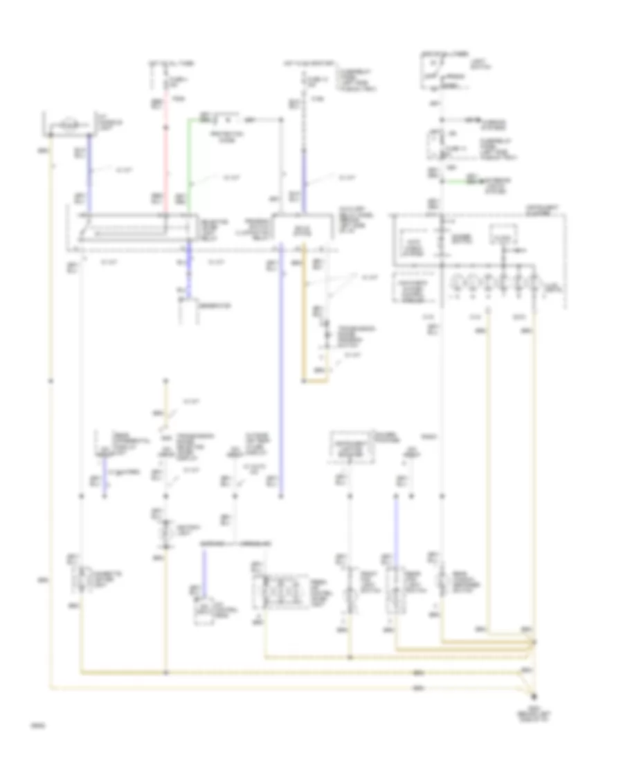
AIR CONDITIONING
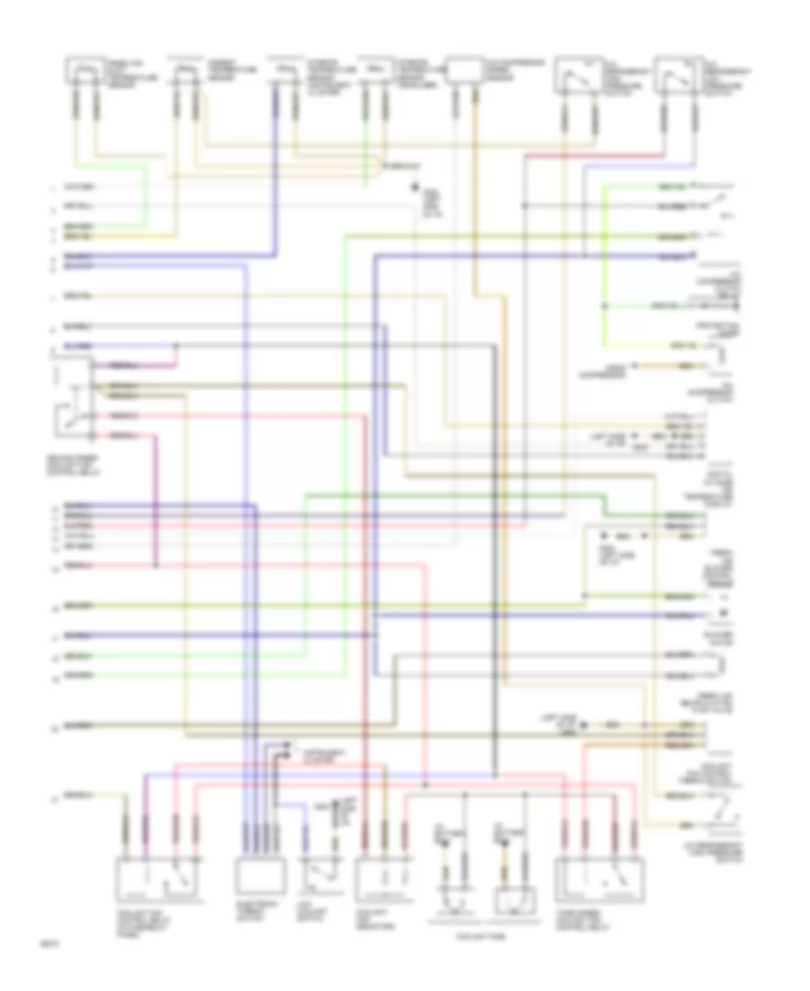
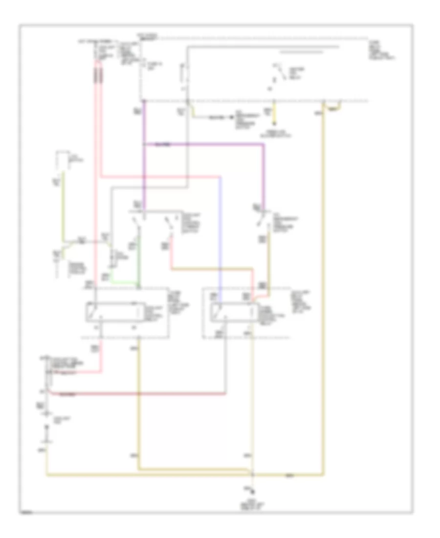
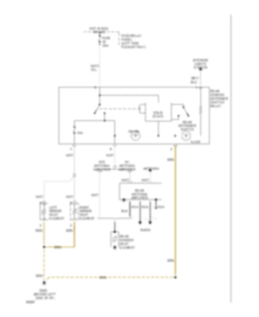
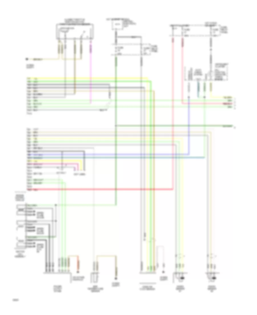
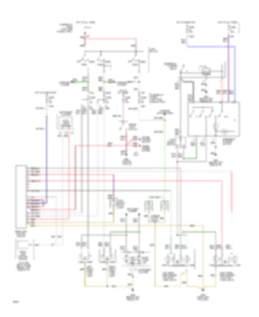
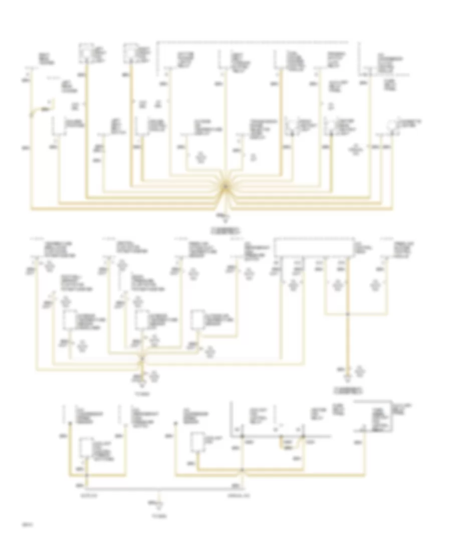
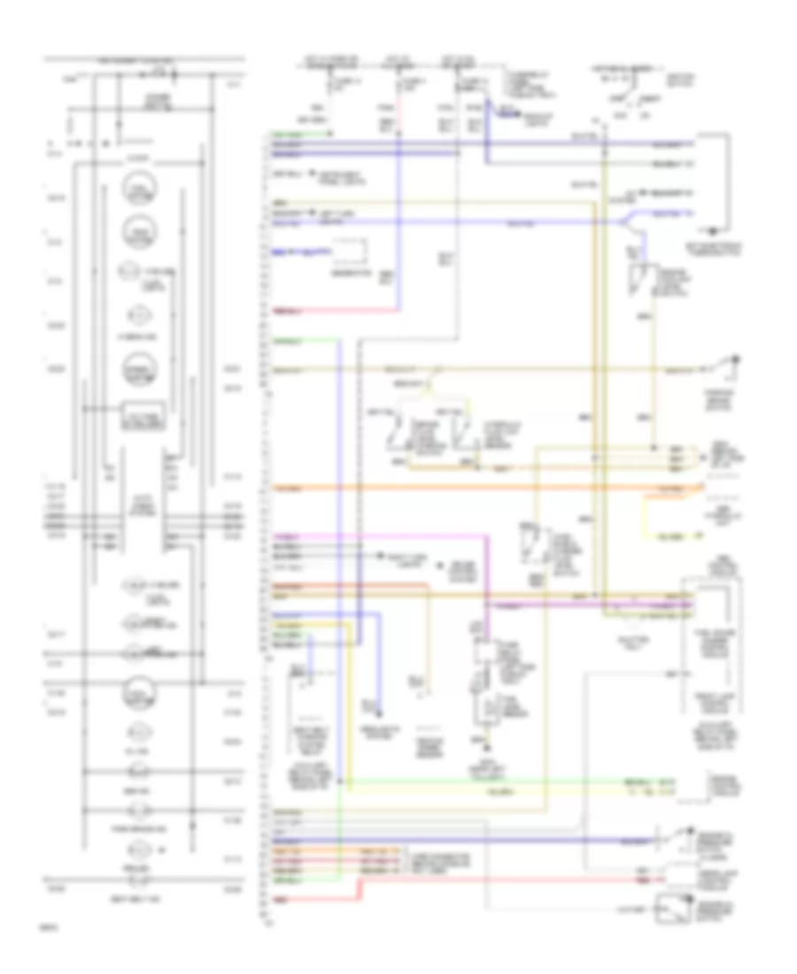
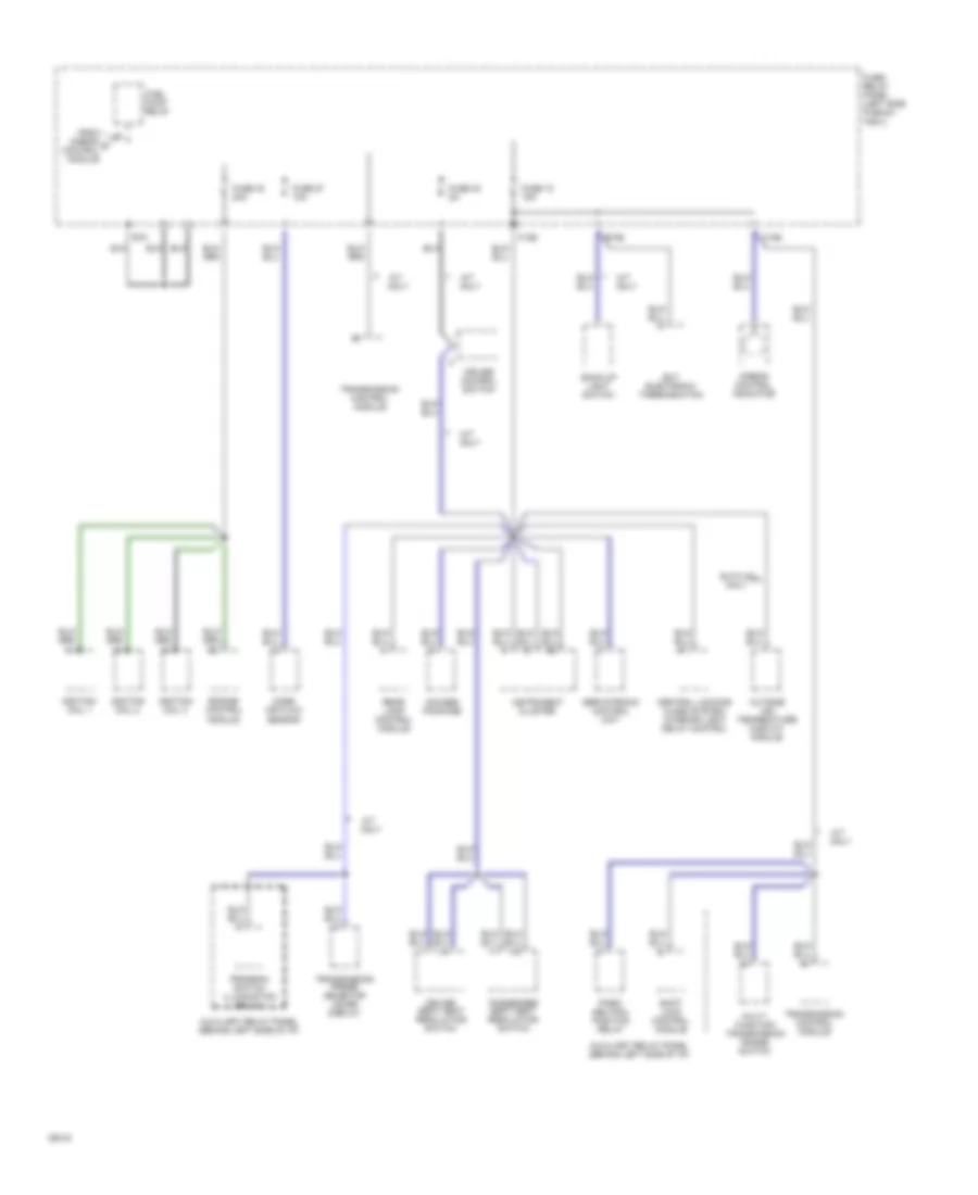
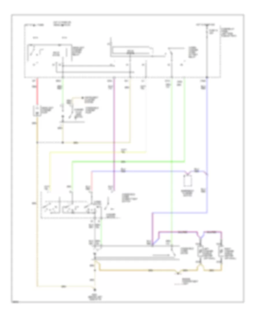
Auto. A/C-Heater System Wiring Diagram (With A/T Wiring Diagram 1 Of 2) for Audi 90 S 1994
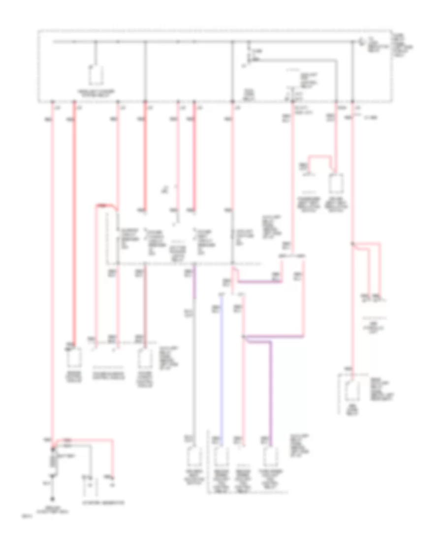
 https://portal-diagnostov.com/license.html
Automotive Electricians Portal FZCO
Automotive Electricians Portal FZCO
https://portal-diagnostov.com/license.html
https://portal-diagnostov.com/license.html
Automotive Electricians Portal FZCO
Automotive Electricians Portal FZCO
List of elements for Auto. A/C-Heater System Wiring Diagram (With A/T Wiring Diagram 1 Of 2) for Audi 90 S 1994:
- (left side of i/p)
- A/c control head
- Air flow flap motor
- Auxiliary relay panel 2
- B10
- Battery (30)
- C10
- C11
- Central flap motor potentiometer
- Data link connector
- Engine control module
- Footwell/defrost flap motor potentiometer
- Fuse 15a
- Fuse 25a
- Fuse 30a
- Fuse 5a
- Fuse 60a
- Fuse/ relay panel
- G202
- G202 (left side of i/p)
- Hot at all times
- Hot w/ lights on
- Hot w/ load reduction relay energized (x)
- Ignition (15)
- Interior temperature sensor fan
- Temp regulator flap motor potentiometer
- Transmission control module
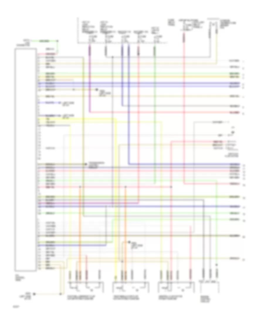
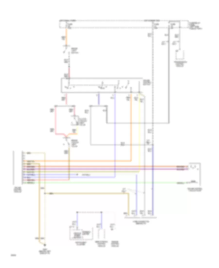
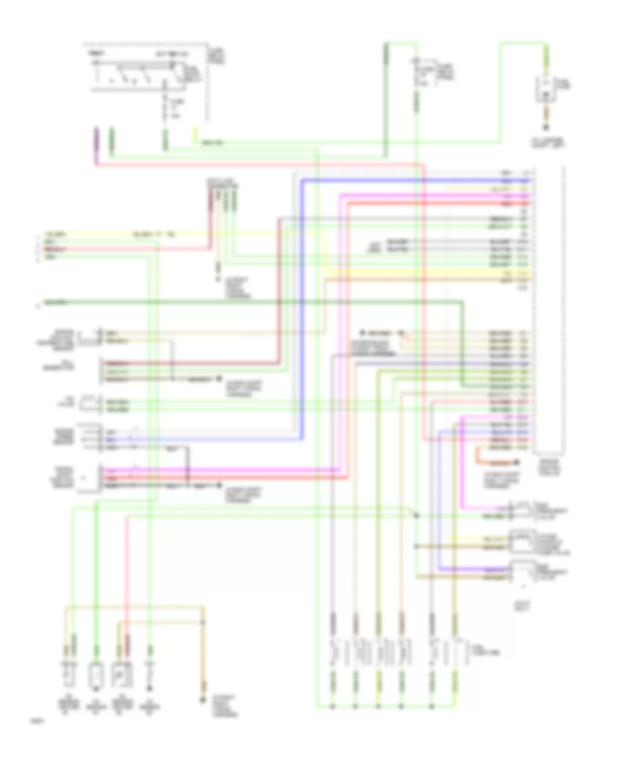
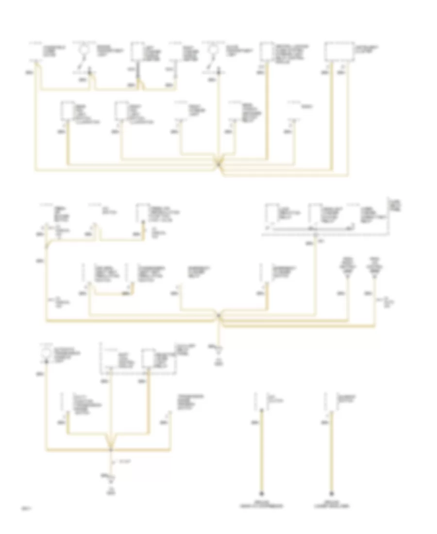
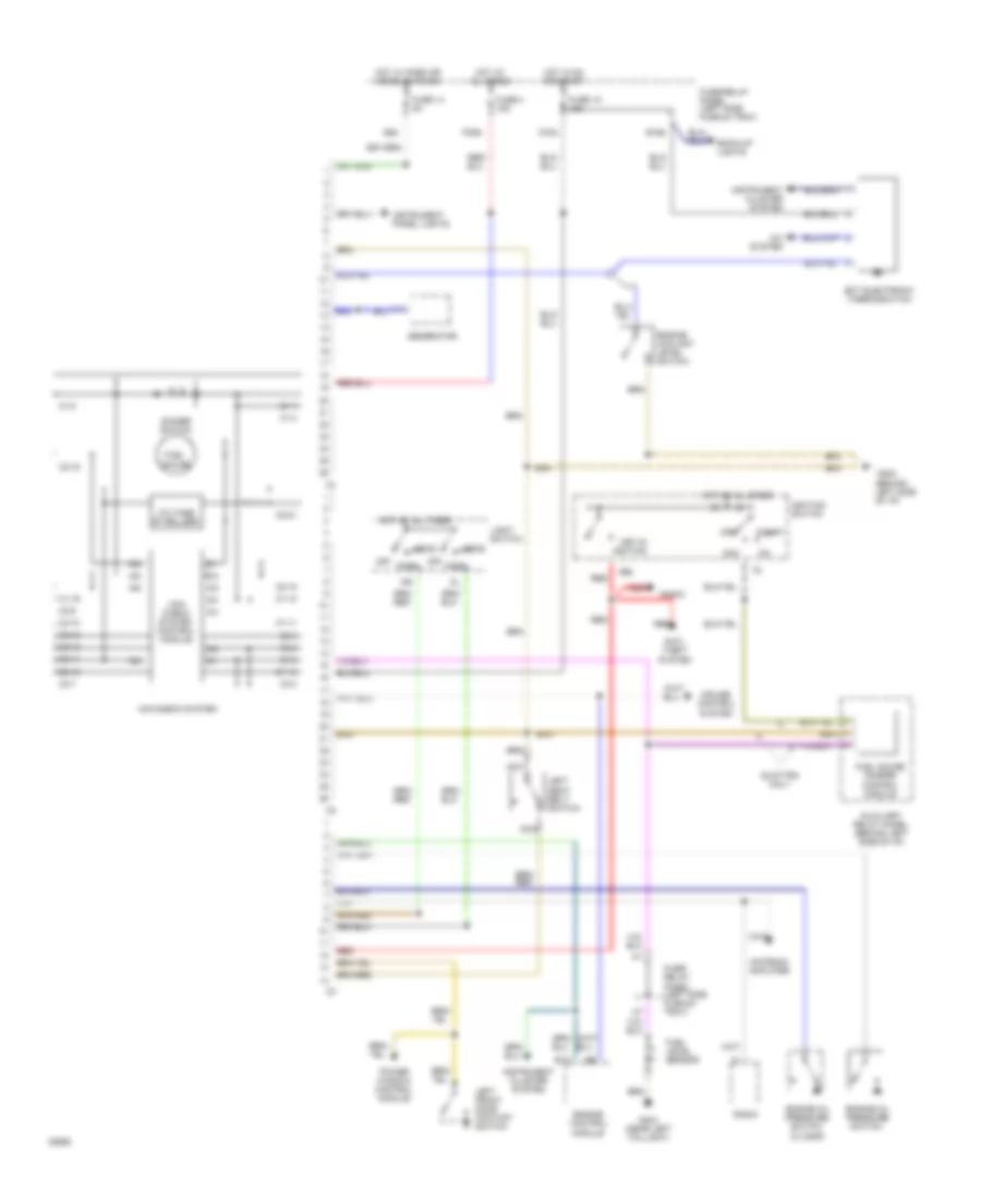
Auto. A/C-Heater System Wiring Diagram (With A/T Wiring Diagram 2 Of 2) for Audi 90 S 1994
List of elements for Auto. A/C-Heater System Wiring Diagram (With A/T Wiring Diagram 2 Of 2) for Audi 90 S 1994:
- (in battery box)
- (left side of i/p)
- (left side of i/p) g202
- (near compressor)
- A/c compressor clutch
- A/c compressor clutch relay
- A/c compressor speed sensor
- A/c refrigerant high pressure switch
- A/c refrigerant low pressure switch
- Ambient temperature sensor
- Blower motor
- Coolant fan control relay (in fuse/relay panel)
- Coolant fan control thermo switch
- Coolant fan resistors
- Coolant fans
- Digital outside air temperature display
- Electronic thermo switch
- Fresh air blower control module
- Fresh air duct temperature sensor
- Fresh air recirculating flap valve
- G202
- G202 (left side of i/p)
- Instrument cluster
- Interior temperature sensor (headliner)
- Interior temperature sensor (instrument cluster)
- Low coolant switch
- Protection diode
- Second speed coolant fan control relay
- Third speed coolant fan control relay
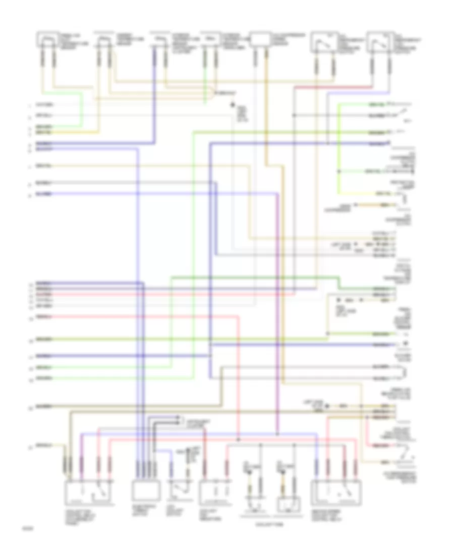
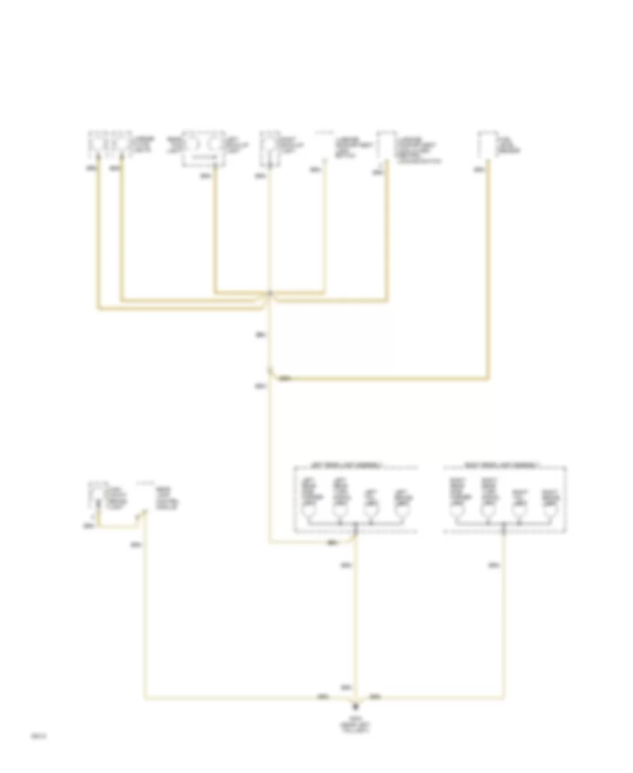
Auto. A/C-Heater System Wiring Diagram (With M/T Wiring Diagram 1 Of 2) for Audi 90 S 1994
List of elements for Auto. A/C-Heater System Wiring Diagram (With M/T Wiring Diagram 1 Of 2) for Audi 90 S 1994:
- (left side of i/p)
- A/c control head
- Air flow flap motor
- Auxiliary relay panel 2
- B10
- Battery (30)
- C10
- C11
- Central flap motor potentiometer
- Data link connector
- Engine control module
- Footwell/defrost flap motor potentiometer
- Fuse 15a
- Fuse 25a
- Fuse 30a
- Fuse 5a
- Fuse 60a
- Fuse/ relay panel
- G202
- G202 (left side of i/p)
- Hot at all times
- Hot w/ lights on
- Hot w/ load reduction relay energized (x)
- Ignition (15)
- Interior temperature sensor fan
- Temp regulator flap motor potentiometer
- Transmission control module
Auto. A/C-Heater System Wiring Diagram (With M/T Wiring Diagram 2 Of 2) for Audi 90 S 1994
List of elements for Auto. A/C-Heater System Wiring Diagram (With M/T Wiring Diagram 2 Of 2) for Audi 90 S 1994:
- (in battery box)
- (left side of i/p)
- (left side of i/p) g202
- (near compressor)
- A/c compressor clutch
- A/c compressor clutch relay
- A/c compressor speed sensor
- A/c refrigerant high pressure switch
- A/c refrigerant low pressure switch
- Ambient temperature sensor
- Blower motor
- Coolant fan control relay (in fuse/relay panel)
- Coolant fan control thermo switch
- Coolant fan resistors
- Coolant fans
- Digital outside air temperature display
- Electronic thermo switch
- Fresh air blower control module
- Fresh air duct temperature sensor
- Fresh air recirculating flap valve
- G202
- G202 (left side of i/p)
- Instrument cluster
- Interior temperature sensor (headliner)
- Interior temperature sensor (instrument cluster)
- Low coolant switch
- Protection diode
- Second speed coolant fan control relay
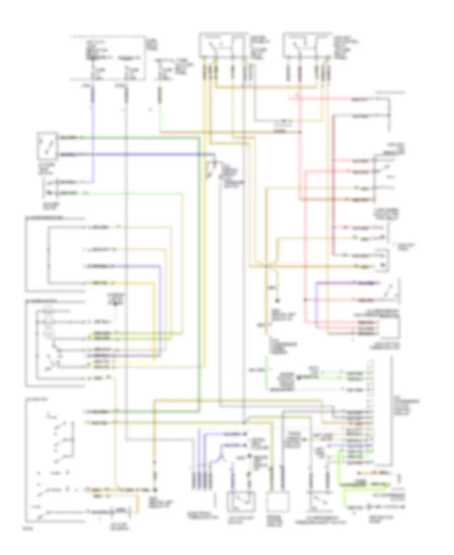
Manual A/C Wiring Diagram for Audi 90 S 1994
List of elements for Manual A/C Wiring Diagram for Audi 90 S 1994:
- (behind left side of i/p)
- (left side i/p)
- (left side of i/p)
- (near compressor)
- A/c compressor clutch
- A/c compressor clutch control module
- A/c compressor speed sensor
- A/c flap solenoid
- A/c refrig- erant low pressure switch
- A/c refrigerant
- A/c refrigerant high pressure switch'
- A/c switch
- Auxiliary relay panel
- Blower motor
- Blower resistors
- Blower switch
- C10
- C11
- Coolant fan control relay (in fuse/ relay panel)
- Coolant fan resistors
- Coolant fan thermo switch
- Coolant fans
- Data link connector
- Diode
- Electronic thermo switch
- Engine control module
- Engine control module pin b10 (engine rpm)
- Fuse 15a
- Fuse 30a
- Fuse 60a
- Fuse/ relay panel
- G202
- G202 (behind left side of i/p)
- Heater fan relay (in fuse/ relay panel)
- Hot at all times
- Hot with load reduction relay energized (x)
- Ignition (15)
- Instru- ment cluster
- Interior lights system
- Low coolant switch
- Off
- Outside temp switch
- Pressure safety switch
- Protection diode
- Third speed coolant fan ctrl relay
- Trans- mission control module
ANTI-LOCK BRAKES
Anti-Lock Brakes Wiring Diagram, FWD for Audi 90 S 1994
List of elements for Anti-Lock Brakes Wiring Diagram, FWD for Audi 90 S 1994:
- (behind left side of i/p)
- (below left
- (left firewall)
- Abs
- Abs combi relay (in rear auxiliary relay panel, below left rear seat)
- Abs return flow pump
- Abs return flow pump relay
- Abs solenoid relay
- Abs solenoid valves
- Abs warning ind.
- All times
- Auxiliary relay panel
- Brake lamp switch
- Connector station
- Control
- Fuse 12 15a
- Fuse 29 10a
- Fuse 31 15a
- Fuse/relay panel (left side plenum tray)
- G202
- Generator
- Hot at
- Hot at all times
- Hot in on or start
- Hydraulic
- Instrument cluster
- Left front wheel sensor
- Left rear wheel sensor
- Module
- Nca
- Rear seat)
- Red
- Red red
- Right front wheel sensor
- Right rear wheel sensor
- Solid state
- Unit
Anti-Lock Brakes Wiring Diagram, Quattro for Audi 90 S 1994
List of elements for Anti-Lock Brakes Wiring Diagram, Quattro for Audi 90 S 1994:
- (behind left side of i/p)
- (below left
- (left firewall)
- Abs
- Abs acceleration switch
- Abs control module
- Abs return flow pump
- Abs return flow pump relay
- Abs solenoid valve relay
- Abs solenoid valves
- Abs warning ind.
- All times
- Auxiliary relay panel
- Auxiliary relay panel, below left rear seat)
- Brake lamp switch
- Connector station
- Electronic differential lock cut-out relay (in rear
- Fuse 12 15a
- Fuse 29 10a
- Fuse 31 15a
- Fuse/relay panel (left side plenum tray)
- G202
- Generator
- Hot at
- Hot at all times
- Hot in on or start
- Hydraulic
- Instrument cluster
- Left front wheel sensor
- Left rear wheel sensor
- Lock indicator light
- Nca
- Rear differential
- Rear differential lock switch
- Rear seat)
- Red
- Red red
- Right front wheel sensor
- Right rear wheel sensor
- Solid state
- Unit
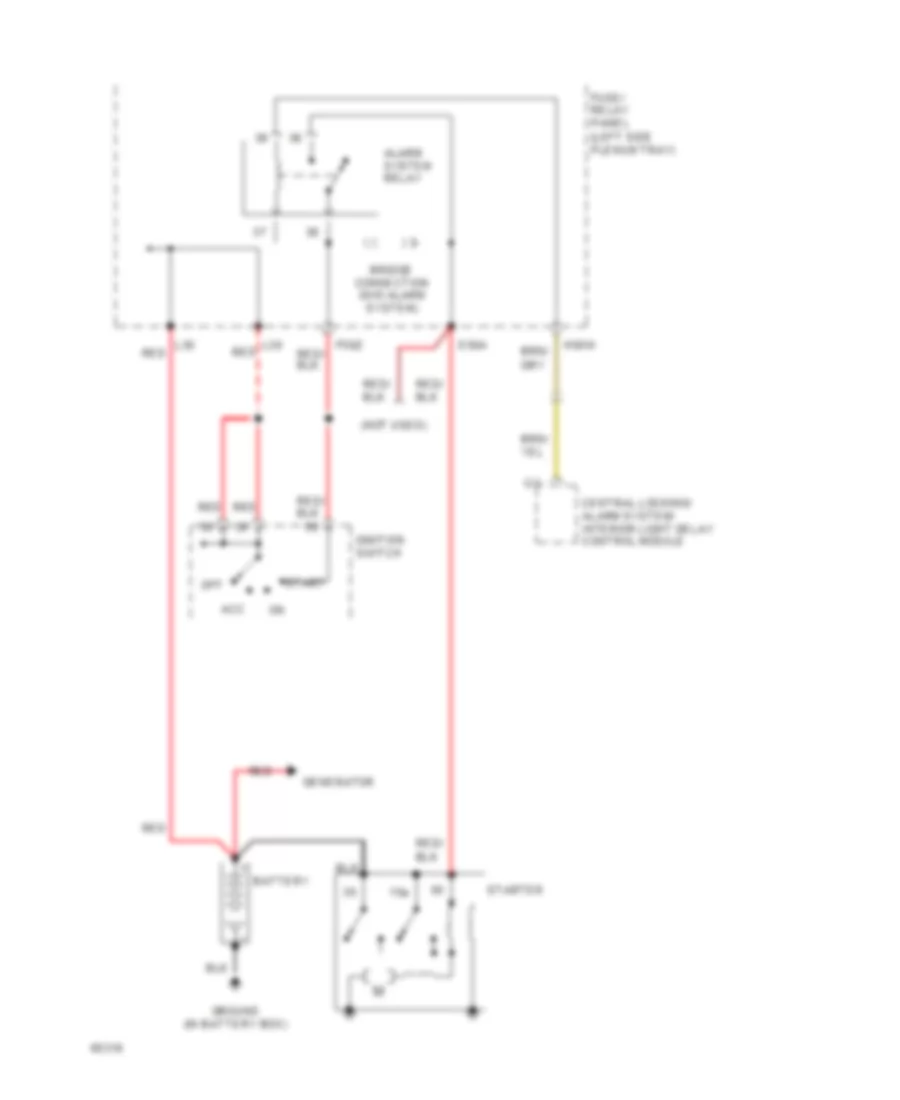
ANTI-THEFT
Anti-theft & Central Locking Wiring Diagram (1 of 2) for Audi 90 S 1994
List of elements for Anti-theft & Central Locking Wiring Diagram (1 of 2) for Audi 90 S 1994:
-
-
-
-
- (a/t) (m/t)
- (left side
- 86s
- A/t
- A/t only
- Acc
- Alarm horn
- Alarm system relay
- All times
- Battery
- C15a
- Central locking/ alarm system/ interior light delay control module
- Control module
- Driver door central locking system switch
- Driver door handle alarm switch
- E50a
- F30al
- F50z
- Front interior light
- Function
- Fuse 10a
- Fuse 15a
- Fuse/relay
- G202 (behind left
- G404 (near left)
- H50w
- Hood
- Hot at
- Hot in on or start
- Ignition
- Key switch
- L30
- M/t
- M30az
- Multi-
- Nca
- Off
- Panel
- Park/ neutral position relay
- Passenger door central locking system switch
- Passenger door handle alarm switch
- Plenum tray)
- Radio
- Red
- Seat belt
- Side of i/p)
- Start
- Starter
- Switch
- Taillight)
- Transmission
- Trunk light
- Trunk light switch
- Trunk lock alarm/ central locking switch
- Turn/ hazard lights
- Warning control module
Anti-theft & Central Locking Wiring Diagram (2 of 2) for Audi 90 S 1994
List of elements for Anti-theft & Central Locking Wiring Diagram (2 of 2) for Audi 90 S 1994:
-
-
-
-
- Left front door contact switch
- Left infrared central locking system sensor
- Left rear door contact switch
- Nca
- Right front door contact switch
- Right infrared central locking system sensor
- Right rear door contact switch
COMPUTER DATA LINES
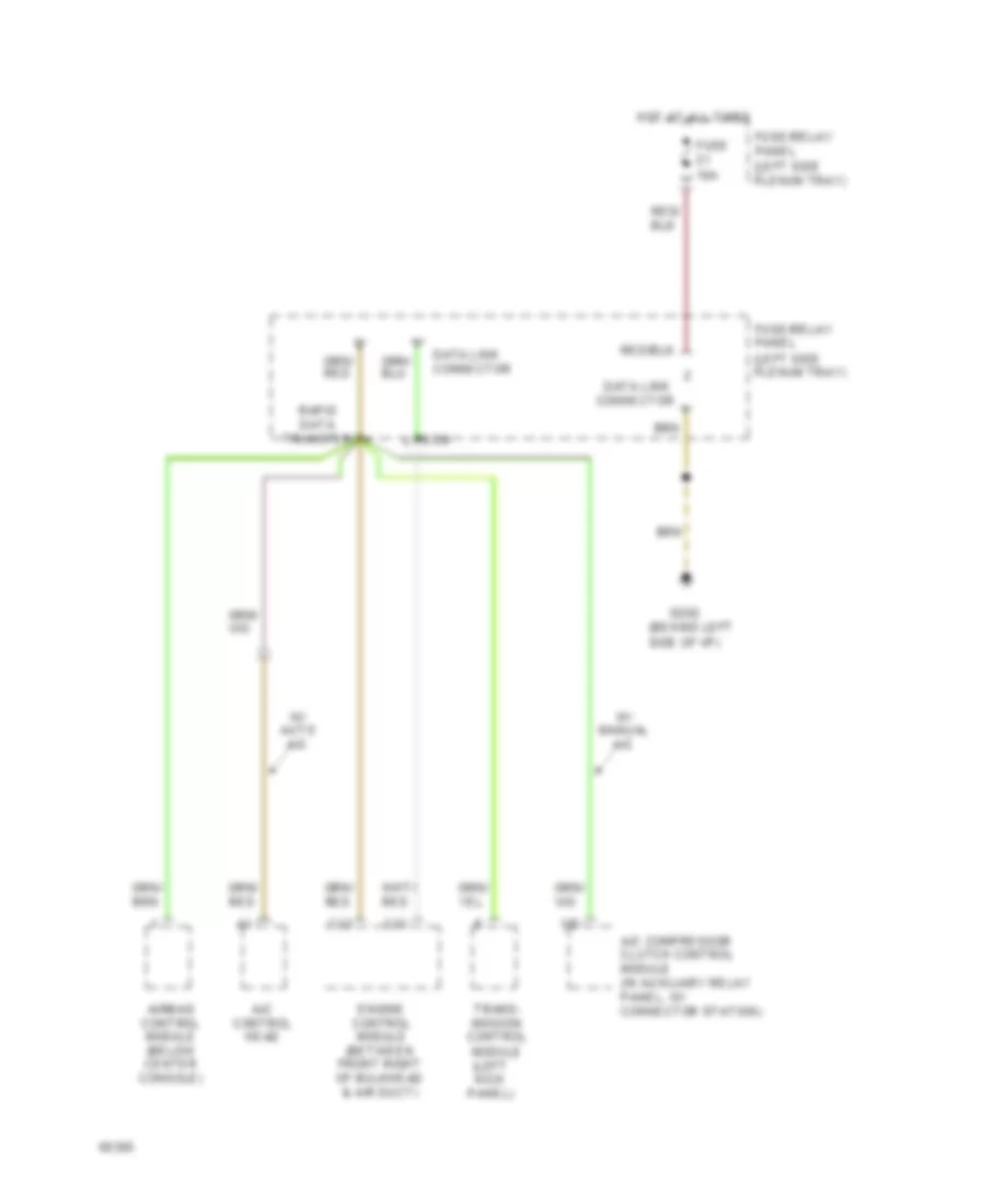
Data Link Connector Wiring Diagram for Audi 90 S 1994
List of elements for Data Link Connector Wiring Diagram for Audi 90 S 1994:
- (behind left side of i/p)
- (left kick panel)
- (left side plenum tray)
- 3/d
- A/c compressor clutch control module (in auxiliary relay panel, w/ connector station)
- A/c control head
- Airbag control module (below center console)
- C12
- C13
- Connector
- Data link
- Data link connector
- Ecm
- Engine control module (between front right of bulkhead & air duct)
- Fuse 10a
- Fuse/relay panel
- G202
- Hot at all times
- Rapid data transfer
- Trans- mission control module
- W/ auto a/c
- W/ manual a/c
COOLING FAN
Cooling Fan Wiring Diagram, A/T with Auto A/C for Audi 90 S 1994
List of elements for Cooling Fan Wiring Diagram, A/T with Auto A/C for Audi 90 S 1994:
- (behind left side of i/p)
- (in battery box)
- (left side plenum tray)
- A/c control head
- A/c refrigerant high pressure switch
- Auxiliary
- Coolant fan fuse 42 60a
- Coolant fan control relay
- Coolant fan control series resistance
- Coolant fan control thermo- switch
- Coolant fans
- D16
- Fuse 15 25a
- Fuse/ relay panel
- Fuse/ relay panel (left side plenum tray)
- G202
- Ground
- Hot at all times
- Hot in run
- Or accy
- Relay panel
- Second speed coolant fan control relay
- Third speed coolant fan control relay
Cooling Fan Wiring Diagram, A/T with Manual A/C for Audi 90 S 1994
List of elements for Cooling Fan Wiring Diagram, A/T with Manual A/C for Audi 90 S 1994:
- (behind left side of i/p)
- (in battery box)
- (left side plenum tray)
- A/c
- A/c refrigerant high pressure switch
- Auxiliary
- C11
- Coolant fan fuse 42 60a
- Coolant fan control relay
- Coolant fan control series resistance
- Coolant fan control thermo- switch
- Coolant fans
- Engine control module
- Fresh air blower switch
- Fuse 15 25a
- Fuse/ relay panel
- Fuse/ relay panel (left side plenum tray)
- G100
- G202
- Heater fan relay
- Hot at all times
- Hot w/load reduction
- Relay energized
- Relay panel
- Second speed coolant fan control relay
- Switch
- Third speed coolant fan control relay
Cooling Fan Wiring Diagram, M/T with Auto A/C for Audi 90 S 1994
List of elements for Cooling Fan Wiring Diagram, M/T with Auto A/C for Audi 90 S 1994:
- (behind left side of i/p)
- (in battery box)
- (left side plenum tray)
- A/c control head
- A/c refrigerant high pressure switch
- Auxiliary
- Coolant fan fuse 42 60a
- Coolant fan control relay
- Coolant fan control series resistance
- Coolant fan control thermo- switch
- Coolant fans
- D16
- Fuse 15 25a
- Fuse/ relay panel
- Fuse/ relay panel (left side plenum tray)
- G202
- Ground
- Hot at all times
- Hot in run
- Or accy
- Relay panel
- Second speed coolant fan control relay
Cooling Fan Wiring Diagram, M/T with Manual A/C for Audi 90 S 1994
List of elements for Cooling Fan Wiring Diagram, M/T with Manual A/C for Audi 90 S 1994:
- (behind left side of i/p)
- (left side plenum tray)
- A/c
- A/c diode
- A/c refrigerant high pressure switch
- Auxiliary
- C11
- Coolant fan
- Coolant fan fuse 42 60a
- Coolant fan control relay
- Coolant fan control series resistance
- Coolant fan control thermo- switch
- Engine control module
- Fresh air blower switch
- Fuse 15 25a
- Fuse/ relay panel
- Fuse/ relay panel (left side plenum tray)
- G202
- Heater fan relay
- Hot at all times
- Hot in run
- Or accy
- Relay panel
- Switch
- Third speed coolant fan control relay
CRUISE CONTROL
Cruise Control Wiring Diagram for Audi 90 S 1994
List of elements for Cruise Control Wiring Diagram for Audi 90 S 1994:
- A/t
- A/t only
- Brake light switch
- Brake vacuum vent valve
- C1-18
- Cluster
- Clutch vacuum vent valve
- Control module
- Cruise control module
- Cruise control switch
- Cruise control vacuum pump
- Engine control module
- Fuse 10a
- Fuse 15a
- Fuse 5a
- Fuse/relay panel (left side plenum tray)
- G200 (behind left side of i/p)
- Hot at all times
- Hot in on or acc
- Instrument
- M/t
- M/t only
- Servotronic control module
- Speedo- meter
- Transmission
- Vehicle speed output
- Wire connector (behind i/p)
DEFOGGERS
Defoggers Wiring Diagram for Audi 90 S 1994
List of elements for Defoggers Wiring Diagram for Audi 90 S 1994:
- 10a
- Antenna
- Fuse 30a
- Fuse/relay panel (left side plenum tray)
- G202 (behind left side of i/p)
- Hot in run
- Illum.
- Interior lights system
- Left mirror heat element
- Nca
- On ind.
- Or acc
- Radio
- Rear antenna amplifier
- Rear defogger switch
- Rear window defogger switch/ relay
- Rear window heat element
- Right mirror heat element
- Solid state
- W/ antenna amplifier
- W/o antenna amplifier
ELECTRONIC POWER STEERING
Electronic Power Steering Wiring Diagram for Audi 90 S 1994
List of elements for Electronic Power Steering Wiring Diagram for Audi 90 S 1994:
-
- (behind left side of i/p)
- (bottom of
- Cluster
- Fuse 12 15a
- Fuse/relay panel (left side plenum tray)
- G202
- Hot in on or start
- Instrument
- Servotronic
- Servotronic control unit (behind glove box)
- Solenoid valve
- Speedo- meter
- Steering column)
ENGINE PERFORMANCE
2.8L
2.8L, Wiring Diagram (Cabriolet & 90 Wiring Diagram 2.8L 1 Of 2) for Audi 90 S 1994
List of elements for 2.8L, Wiring Diagram (Cabriolet & 90 Wiring Diagram 2.8L 1 Of 2) for Audi 90 S 1994:
- (in eng compt)
- (not used)
- (on intake manifold)
- 10a
- 15a
- 20a
- A/t only
- A10
- A11
- A12
- Auto check system
- B10
- B11
- B12
- B13
- B14
- B15
- B16
- B17
- B18
- B19
- B20
- Central electrical unit
- Closed throttle position switch/ throttle position sensor
- Egr temperature sensor
- Engine control module
- Fuse
- Fuse/ relay panel
- Hot at all times
- Hot in run or start
- Hot in start or run
- Ignition coil assembly
- Instrument cluster
- Knock sensor #1
- Knock sensor #2
- Mal- function indicator "check engine"
- Mass air flow sensor
- Nca
- Power output stage
- Red
- Spark plugs #1 & #6
- Spark plugs #2 & #4
- Spark plugs #3 & #5
- Tach
- Vehicle speed out
2.8L, Wiring Diagram (Cabriolet & 90 Wiring Diagram 2.8L 2 Of 2) for Audi 90 S 1994
List of elements for 2.8L, Wiring Diagram (Cabriolet & 90 Wiring Diagram 2.8L 2 Of 2) for Audi 90 S 1994:
- (calif only)
- (in eng compt right wiring harness)
- (in luggage compt, left)
- (in right front wiring harness)
- (not used)
- (on eng block, in right front wiring harness)
- 15a
- Battery(30)
- C1
- C10
- C11
- C12
- C13
- C14
- C15
- C16
- Crank- shaft position sensor
- D10
- D11
- D12
- D13
- D14
- D15
- D16
- Data link connector
- Eap frequency valve
- Egr frequency valve
- Engine control module
- Engine coolant temperature sensor
- Engine speed sensor
- Fuel injectors
- Fuel pump
- Fuel pump relay
- Fuse
- Fuse/ relay panel
- Hall generator
- Iac valve
- Ign(15)
- Intake manifold change- over valve
- Nca
- O2 sensor #1
- O2 sensor #2
- O2 sensor heater
- Red
EXTERIOR LIGHTS
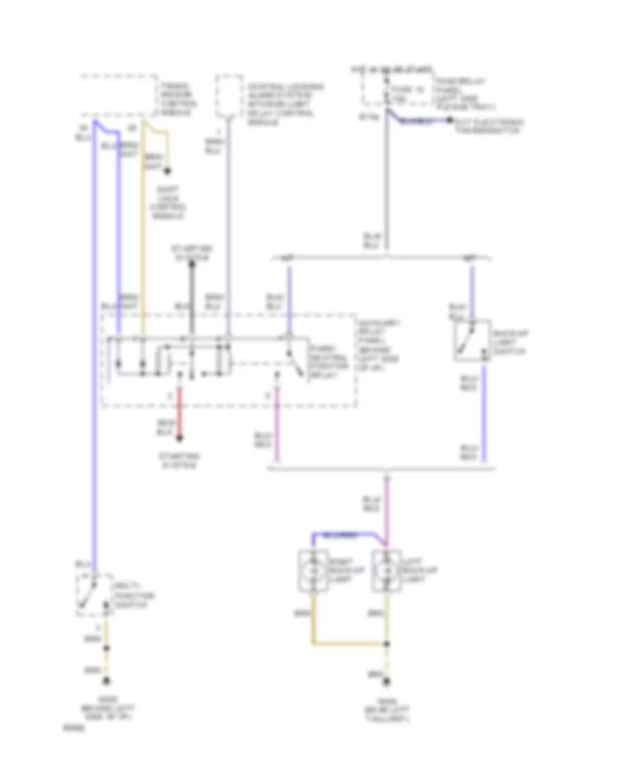
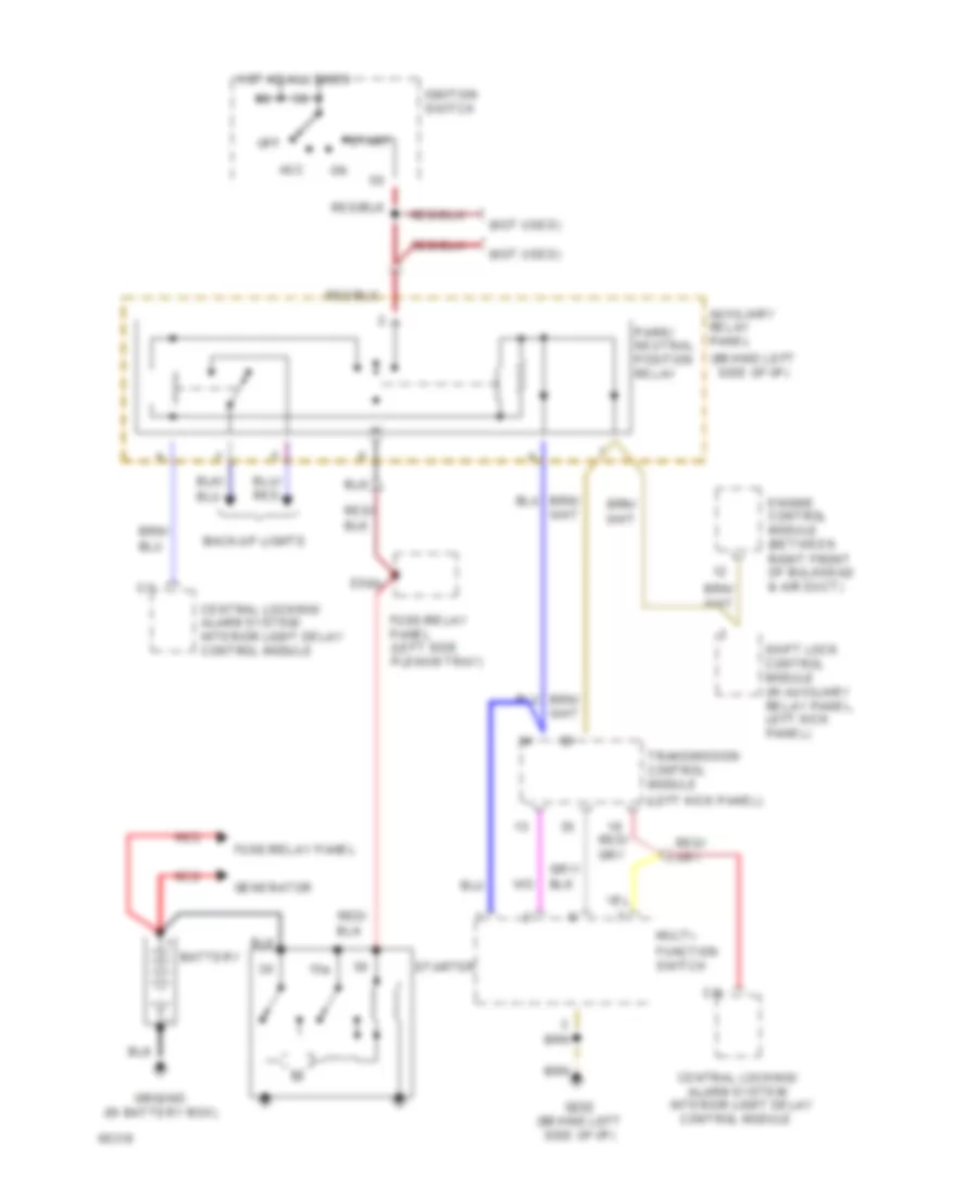
Back-up Lamps Wiring Diagram for Audi 90 S 1994
List of elements for Back-up Lamps Wiring Diagram for Audi 90 S 1994:
- A/t
- Auxiliary relay panel (behind left side of i/p)
- B15a
- Back-up light switch
- Central locking/ alarm system/ interior light delay control module
- Ect electronic thermoswitch
- Function switch
- Fuse 12 15a
- Fuse/relay panel (left side plenum tray)
- G202 (behind left side of i/p)
- G404 (near left taillight)
- Hot in on or start
- Left back-up light
- M/t
- Multi-
- Park/ neutral position relay
- Right back-up light
- Shift lock control module
- Starting system
- Trans- mission control module
Park, Marker, Stop, Tail & Turn Lamps Wiring Diagram, Canada for Audi 90 S 1994
List of elements for Park, Marker, Stop, Tail & Turn Lamps Wiring Diagram, Canada for Audi 90 S 1994:
-
- fuse 5a
- hot in on or start
- (left side
- A/t only
- Abs control module
- Anti-theft system
- Auto- check system
- Auxiliary relay panel (behind left side of i/p)
- Brake light switch
- C15a
- Cluster
- Cruise control switch
- D 58l
- Daytime running lights relay
- E 58r
- Emergency flasher relay
- Emergency flasher switch
- F57l
- Front lamp control module
- Fuse 10a
- Fuse 15a
- Fuse 5a
- Fuse/relay
- G202 (behind left side of i/p)
- G404 (near left taillight)
- G49
- G57r
- H 58l
- H 58r
- Head
- Headlights
- High- mount stop light
- Hot at all times
- Hot in on or acc
- I58d
- I75aw
- Instrument
- Instrument cluster
- Instrument cluster system (dimmer switch)
- J30
- J58
- L30
- Left front park/ turn light
- Left rear side marker/ tail/stop/ turn lights
- Left turn ind.
- License plate lights
- Light switch
- Mkr
- Off
- Panel
- Park
- Plenum tray)
- Rear lamp control module
- Red
- Right front park/ turn light
- Right rear side marker/ tail/stop/ turn lights
- Right turn ind.
- Signal switch
- Solid state
- Stop
- System
- Tail
- Trans- mission system
- Turn
- Warnings
Park, Marker, Stop, Tail & Turn Lamps Wiring Diagram, USA for Audi 90 S 1994
List of elements for Park, Marker, Stop, Tail & Turn Lamps Wiring Diagram, USA for Audi 90 S 1994:
-
- hot in on or start
- (left side
- A/t only
- Abs control module
- Anti-theft system
- Auto- check system
- Auxiliary relay panel (behind left side of i/p)
- Brake light switch
- C15a
- Cluster
- Cruise control switch
- D 58l
- E 58r
- Emergency flasher relay
- Emergency flasher switch
- F57l
- Front lamp control module
- Fuse 10a
- Fuse 15a
- Fuse 5a
- Fuse/relay
- Fuse/relay panel (left side plenum tray)
- G202 (behind left side of i/p)
- G404 (near left taillight)
- G49
- G57r
- H 58l
- H 58r
- Head
- High- mount stop light
- Hot at all times
- Hot in on or acc
- I58d
- I75aw
- Instrument
- Instrument cluster
- Interior
- J58
- L30
- Left front park/ turn light
- Left rear side marker/ tail/stop/ turn lights
- Left turn ind.
- License plate lights
- Light switch
- Lights system
- Mkr
- Off
- Panel
- Park
- Plenum tray)
- Rear lamp control module
- Red
- Right front park/ turn light
- Right rear side marker/ tail/stop/ turn lights
- Right turn ind.
- Signal switch
- Solid state
- Stop
- System
- Tail
- Trans- mission system
- Turn
- Warnings
GROUND DISTRIBUTION
Ground Distribution Wiring Diagram (1 of 6) for Audi 90 S 1994
List of elements for Ground Distribution Wiring Diagram (1 of 6) for Audi 90 S 1994:
- Battery
- Closed
- Coolant fan
- Crankshaft position sensor
- D1 d1
- D16
- Egr temperature sensor
- Engine
- Engine control module
- Engine coolant temperature sensor
- Engine speed sensor
- G131 (intake manifold)
- Generator
- Ground (in battery box)
- Ground strap
- Hall sensor
- Mass air flow sensor
- Nca
- Power distribution system
- Power output stage
- Red
- Sensor shields
- Switch
- Throttle position
- Throttle position sensor
- Transmission control module
- Transmission vehicle speed
- W/ a/t
- W/ auto a/c
Ground Distribution Wiring Diagram (2 of 6) for Audi 90 S 1994
List of elements for Ground Distribution Wiring Diagram (2 of 6) for Audi 90 S 1994:
- (in console)
- Alarm horn
- Auxiliary relay panel
- Cruise control module
- Driver's backrest heat element
- Driver's front seat switch
- Driver's seat heater temperature sensor
- Driver's side heated mirror
- From a/c compressor speed sensor
- From abs control module
- From airbag control module
- From emergency flasher relay
- From high tone horn
- From interior temp. sensor (i/p)
- From oxygen sensor heater 1
- From passenger's door handle alarm switch
- From transmission range program switch
- G202 (behind left side of i/p)
- Headlight washer pump
- Hood alarm switch
- Left heated door lock control module
- Left rear window switch
- Mirror adjust switch
- Passenger's backrest heat element
- Passenger's seat heater temperature sensor
- Passenger's side heated mirror
- Power window control module
- Power window/ sunroof control module
- Right front window switch
- Right heated door lock control module
- Right rear window switch
- Servotronic control module
- W/ a/t
- W/ abs
- W/ auto a/c
- W/ sunroof
- W/o sunroof
Ground Distribution Wiring Diagram (3 of 6) for Audi 90 S 1994
List of elements for Ground Distribution Wiring Diagram (3 of 6) for Audi 90 S 1994:
- Abs combi relay
- Abs control module
- Airbag control lamp relay
- Airbag control module
- Auxiliary relay panel
- B/3
- Beam
- Brake fluid level warning switch
- C/9
- Central locking/ alarm system/ interior light delay control module
- Data link connector
- Differential lock control module
- Differential lock switch illumination
- Driver's door central locking system switch
- Driver's door handle alarm switch
- Elc warning switch
- Front lamp control module
- Fuse/ relay panel
- High tone horn
- Hydraulic fluid low level sensor
- Kick- down switch
- Left front fog light
- Left front park light
- Left front turn signal light
- Left headlights
- Left infrared central locking system sensor
- Low tone horn
- Only
- Oxygen sensor heater 1
- Oxygen sensor heater 2
- Passenger's door central locking system switch
- Passenger's door handle alarm switch
- Quattro
- Quattro only
- Rear auxiliary relay panel
- Rear differential lock switch
- Rear differential lock switch illumination
- Right front fog light
- Right front park light
- Right front turn signal light
- Right headlights
- Right infrared central locking system sensor
- To g202
- Trunk lock alarm/ central locking switch
- Vehicle speed sensor
- W/ a/t
- W/ abs
- W/ auto check system
- W/ drl
- Windshield washer pump & fluid level warning switch
Ground Distribution Wiring Diagram (4 of 6) for Audi 90 S 1994
List of elements for Ground Distribution Wiring Diagram (4 of 6) for Audi 90 S 1994:
- A/c compressor clutch control module
- A/c compressor speed sensor
- A/c control head
- A/c refrigerant high pressure switch
- A12
- A30k
- A86k
- A86m
- Auto a/c
- Auxiliary relay panel
- Back pressure flap motor potentiometer
- Center
- Central flap motor potentiometer
- Cigarette lighter
- Coolant fan
- Coolant fan control relay
- Coolant fan control thermo- switches
- Cruise control module
- D14
- D15
- Daytime running lights relay
- Footwell/ defrost flap motor potentiometer
- Fresh air blower control
- Fresh air intake duct temperature sensor
- Front ashtray light
- Fuel gauge damper control module
- Fuse/ relay panel
- Gauges package
- Heater fan relay
- Interior temperature sensor (headliner)
- Interior temperature sensor (i/p)
- Left front fog light
- Left rear woofer
- Left seat belt switch
- Manual a/c
- Module
- Outside air temperature display
- Outside air temperature sensor
- Program switch illum. relay
- Rear ashtray light
- Right front fog light
- Right rear woofer
- Seat belt warning system relay
- Temperature regulator flap motor potentiometer
- Third speed coolant fan control relay
- To emergency flasher relay
- To g202
- Transmission range selector lever display
- W/ a/t
- W/ auto a/c
- W/ drl
- W/ manual a/c
- W/o drl
Ground Distribution Wiring Diagram (5 of 6) for Audi 90 S 1994
List of elements for Ground Distribution Wiring Diagram (5 of 6) for Audi 90 S 1994:
- A/c clutch
- A/c switch
- Automatic transmission console light
- Auxiliary relay panel
- C/3
- Central locking/ alarm system/ interior light delay control module
- Driver's seat heat regulating switch
- Emergency flasher relay
- Emergency flasher switch
- Engine compartment light
- Fresh air blower switch
- Fresh air recirculating flap two- way valve
- From a/c control head
- From front ashtray light
- Front fog light switch/ illumination
- Front interior light
- Fuse/ relay panel
- G31
- Glove compartment light
- Ground (near a/c compressor)
- Ground (under headliner)
- Headlight washer system relay
- Instrument cluster
- Left washer nozzle heater
- Load reduction relay
- Multi- function transmission range switch
- Nca
- Passenger's seat heat regulating switch
- Radio
- Rear fog light switch/ illumination
- Rear window defogger switch/ relay
- Right washer nozzle heater
- Selector lever light relay
- Shift lock control module
- Sunroof switch
- To g202
- Transmission range program switch
- W/ a/t
- W/ auto a/c
- W/ manual a/c
- Windshield wiper motor
- Wiper/ washer intermittent relay
Ground Distribution Wiring Diagram (6 of 6) for Audi 90 S 1994
List of elements for Ground Distribution Wiring Diagram (6 of 6) for Audi 90 S 1994:
- Fuel level sensor
- G404 (near left taillight)
- High mount brake light
- Left back-up light
- Left brake light
- Left rear lamp assembly
- Left rear side marker light
- Left rear turn signal light
- Left tail light
- License plate lights
- Luggage compartment light switch
- Luggage compartment lock alarm/ central locking switch
- Rear fog light
- Rear lamp control module
- Right back-up light
- Right brake light
- Right rear lamp assembly
- Right rear side marker light
- Right rear turn signal light
- Right tail light
HEADLIGHTS
Fog Lamps Wiring Diagram, Canada for Audi 90 S 1994
List of elements for Fog Lamps Wiring Diagram, Canada for Audi 90 S 1994:
- (behind left side of i/p)
- (near left taillight)
- 56a
- 75n
- Acc
- All times
- C56ak
- D56ar
- Dimmer switch
- F55
- Fog light relay
- Fog light switch
- Ftp
- Fuse 10a
- Fuse 15a
- Fuse/relay panel (left side plenum tray)
- G202
- G404
- G85n
- G86n
- Head
- Headlight dimmer/ flasher switch
- Hi beam indicator
- Hot at
- Hot in on or acc
- I56a
- Ignition switch
- Interior lights system
- L30
- Left front fog light
- Light switch
- M75s
- Off
- Park
- Rear fog light
- Rear fog light switch
- Red
- Right front fog light
- Right head- light
- Run
- Start
Fog Lamps Wiring Diagram, USA for Audi 90 S 1994
List of elements for Fog Lamps Wiring Diagram, USA for Audi 90 S 1994:
- (behind left side of i/p)
- (near left taillight)
- 56a
- 75n
- Acc
- All times
- C56ak
- D56ar
- Dimmer switch
- F55
- Fog light relay
- Fog light switch
- Ftp
- Fuse 10a
- Fuse 15a
- Fuse/relay panel (left side plenum tray)
- G202
- G404
- G85n
- G86n
- Head
- Headlight dimmer/ flasher switch
- Hi beam indicator
- Hot at
- Hot in on or acc
- I56a
- Ignition switch
- Interior lights system
- L30
- Left front fog light
- Light switch
- M75s
- Off
- Park
- Rear fog light
- Rear fog light switch
- Red
- Right front fog light
- Right head- light
- Run
- Start
Headlamps Wiring Diagram, Canada for Audi 90 S 1994
List of elements for Headlamps Wiring Diagram, Canada for Audi 90 S 1994:
-
- (behind left side of i/p)
- 56a
- 56b
- Acc
- All times
- Auto- check system
- Auxiliary relay panel (behind left side of i/p)
- C56ak
- D 58l
- D56ar
- D56al
- D56bl
- D56br
- Daytime running lights relay
- Dimmer switch
- E 58r
- Exterior lights system
- F56b
- F57l
- Fog light relay
- Front lamp control module
- Ftp
- Fuse 10a
- Fuse 5a
- Fuse/ relay panel (left side plenum tray)
- Fuse/relay panel (left side plenum tray)
- G202
- G57r
- H 58l
- H 58r
- Head
- Headlight dimmer/ flasher switch
- Hi beam ind.
- Hot at
- I56a
- Ignition switch
- Instrument cluster
- J30
- L30
- Left front park/ turn light
- Left head- light
- Light switch
- Lisence plate lights
- Load reduction relay
- Off
- Park
- Rear lamp control module
- Red
- Right front park/ turn light
- Right head- light
- Run
- Series resistance wire
- Start
- Turn
- Warnings system
Headlamps Wiring Diagram, USA for Audi 90 S 1994
List of elements for Headlamps Wiring Diagram, USA for Audi 90 S 1994:
- (behind left side of i/p)
- 56a
- 56b
- Acc
- All times
- Auto- check system
- Auxiliary relay panel (behind left side of i/p)
- C56ak
- D56ar
- D56al
- D56bl
- D56br
- Dimmer switch
- Exterior lamps
- F56b
- Fog light relay
- Front lamp control module
- Ftp
- Fuse 10a
- Fuse/ relay panel (left side plenum tray)
- Fuse/relay panel (left side plenum tray)
- G202
- Head
- Headlight dimmer/ flasher switch
- Hi beam ind.
- Hot at
- I56a
- Ignition switch
- Instrument cluster
- L30
- Left head- light
- Light switch
- Off
- Park
- Rear lamp control module
- Red
- Right head- light
- Run
- Start
- System
- Warnings system
HORN
Horn Wiring Diagram for Audi 90 S 1994
List of elements for Horn Wiring Diagram for Audi 90 S 1994:
- Acc
- Dual horn relay
- E87h
- Fuse 3 25a
- Fuse/relay panel (left side plenum tray)
- G202 (behind left side of i/p)
- G71
- G75
- High note horn
- Horn button
- Hot at all times
- Ignition switch
- Load reduction relay
- Low note horn
- Off
- Start
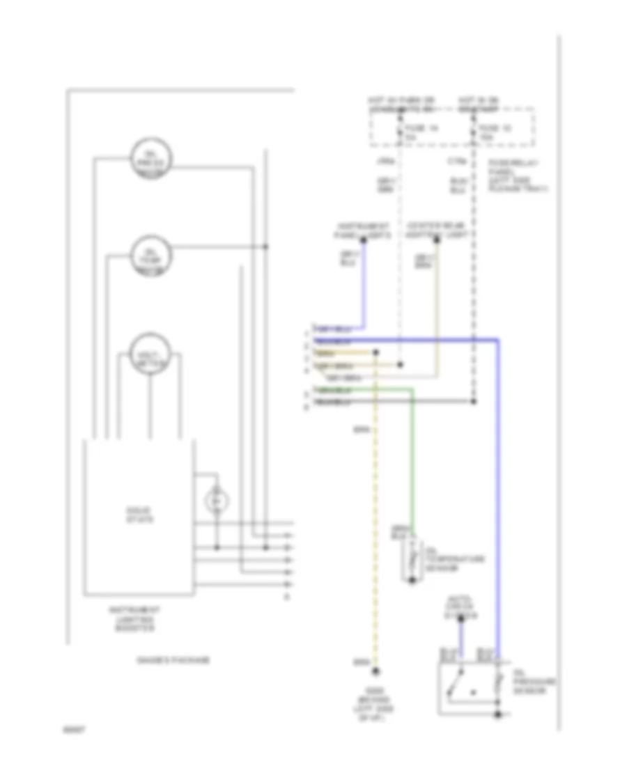
INSTRUMENT CLUSTER
Instrument Panel Wiring Diagram (90 Wiring Diagram 1 Of 2) for Audi 90 S 1994
List of elements for Instrument Panel Wiring Diagram (90 Wiring Diagram 1 Of 2) for Audi 90 S 1994:
- (0.3 bar)
- (3 bulbs)
- (behind left side of i/p)
- 5/1
- 5/2
- 5/3
- 5/5
- 6/1
- 6/2
- 6/3
- 6/4
- 6/5
- 6/6
- A/c system
- Abs control module
- Abs hydraulic unit
- Abs ind.
- Acc
- Auto check system
- Auxiliary relay panel (behind left side of i/p)
- B10
- B15a
- Back-up lights
- Brake fluid level warning switch
- C1-1
- C1-10
- C1-13
- C1-19
- C1-2
- C1-22
- C1-23
- C1-25
- C1-3
- C1-5
- C1-8
- C1-9
- C14
- C15a
- C2-10
- C2-15
- C2-16
- C2-17
- C2-18
- C2-20
- C2-21
- C2-23
- C2-24
- C2-25
- C2-26
- C3-16
- C3-17
- C3-18
- C3-19
- C3-20
- C3-21
- C3-22
- C3-23
- C3-25
- Clock
- Control module
- Cruise control system
- Dimmer switch
- Ect electronic thermoswitch
- Engine
- Engine coolant level switch
- Engine oil pressure
- F30al
- Front lamp control module
- Fuel gauge
- Fuel gauge damper control module
- Fuel level sensor
- Fuse 12 15a
- Fuse 14 5a
- Fuse 4 15a
- Fuse/ relay panel (left side plenum tray)
- Fuse/relay panel (left side plenum tray)
- G202
- G404 (near left taillight)
- Gen ind.
- Generator
- Headlights system
- Hi beam ind.
- Hot at all times
- Hot in on or start
- Hot w/ park or headlights on
- Hydraulic fluid low level sensor
- I58d
- Ignition switch
- Illum. lights
- Instrument cluster
- Instrument panel lights
- Left turn ind.
- Left turn lights
- Lights
- Mil ind.
- Off
- Park brake ind.
- Parking brake switch
- Quattro only
- Rear lamp control module
- Red
- Right turn
- Right turn ind.
- Seat belt ind.
- Seat belt warning system relay
- Speed- ometer
- Start
- Switch
- Tach- ometer
- Temp gauge
- Vehicle speed sensor
- Voltage stabilizer
- Wind- shield washer fluid level switch
- Wire connector (behind console) (not used)
Instrument Panel Wiring Diagram (90 Wiring Diagram 2 Of 2) for Audi 90 S 1994
List of elements for Instrument Panel Wiring Diagram (90 Wiring Diagram 2 Of 2) for Audi 90 S 1994:
- (behind left side
- Auto- check system
- C15a
- Center rear ashtray light
- Fuse 12 15a
- Fuse 14 5a
- Fuse/relay panel (left side plenum tray)
- G202
- Gauges package
- Hot in on or start
- Hot w/ park or headlights on
- Instrument lighting booster
- Instrument panel lights
- J58a
- Of i/p)
- Oil press gauge
- Oil pressure sensor
- Oil temp gauge
- Oil temperature sensor
- Solid state
- Volt- meter
INTERIOR LIGHTS
Courtesy Lamps Wiring Diagram (1 of 2) for Audi 90 S 1994
List of elements for Courtesy Lamps Wiring Diagram (1 of 2) for Audi 90 S 1994:
-
- (optional)
- Anti- theft system
- C1/1
- Center rear ashtray light
- Central locking/ alarm system/ interior light delay control module
- Cluster
- Door
- Engine comp- artment light
- F30al
- Front interior light
- Fuse 14 5a
- Fuse 4 15a
- Fuse/relay panel (left side plenum tray)
- G202 (behind left side of i/p)
- G404 (near left taillight)
- Gauges package
- Glove comp- artment light
- H30b
- Head
- Headlight washer system relay
- Hot at all times
- I58d
- Instrument
- Instrument lighting booster
- J58
- J58a
- Left front door contact switch
- Left make-up mirror light
- Left rear door contact switch
- Left rear reading light
- License plate lights
- Light switch
- Nca
- Off
- Park
- Right front door contact switch
- Right front reading light
- Right make-up mirror light
- Right rear door contact switch
- Right rear reading light
- Trunk light
- Trunk light switch
Courtesy Lamps Wiring Diagram (2 of 2) for Audi 90 S 1994
List of elements for Courtesy Lamps Wiring Diagram (2 of 2) for Audi 90 S 1994:
- C15a
- Driver seat heat regulating switch
- Emergency flasher switch
- Fuse 12 15a
- Fuse 15 25a
- Fuse 18 5a
- Fuse/relay panel (left side plenum tray)
- G202 (behind left side of i/p)
- Hot in on or acc
- Hot in on or start
- I75aw
- M75as
- Mirror adjustment switch
- Passenger seat heat regulating switch
- Wiper/ washer system
Instrument Illumination Wiring Diagram for Audi 90 S 1994
List of elements for Instrument Illumination Wiring Diagram for Audi 90 S 1994:
- A/c control head
- A/t console light
- Ashtray light
- Auto a/c
- Auto check system
- Auxiliary relay panel (behind left side of i/p)
- C1-1
- C1-5
- C1-8
- C15a
- C2-21
- Cigarette lighter light
- Clock
- Dim input
- Dimmer switch
- Exterior
- F30al
- Fresh air control lever light
- Front fog light switch
- Fuse 12 15a
- Fuse 14 5a
- Fuse 4 15a
- Fuse/relay panel (left side plenum tray)
- G202 (behind left side of i/p)
- Gauges package
- Generator
- Gnd
- Head
- Hot at all times
- Hot in on or start
- I58d
- Illum. lights
- Instrument cluster
- Instrument lighting booster
- J58
- Light switch
- Lights system
- Manual a/c
- Mini-check system control module
- Off
- Outside air temp- ature display
- Park
- Program switch illumination relay
- Protection diode
- Radio
- Rear differential display unit
- Rear fog light switch
- Rear window defogger switch
- Selector lever light relay
- Solid state
- Transmission range program switch
- Transmission range selector lever display
- W/ a/t
- W/ auto a/c
- W/ quatrro
- Warning systems
POWER DISTRIBUTION
Power Distribution Wiring Diagram (1 of 4) for Audi 90 S 1994
List of elements for Power Distribution Wiring Diagram (1 of 4) for Audi 90 S 1994:
- (a/t)
- (m/t)
- A/t
- A30m
- Abs combi relay
- Abs hydraulic unit
- Auxiliary relay panel (behind left side of i/p)
- B20
- Battery
- Control module
- Coolant fan control relay
- Coolant fan fuse 60a
- Daytime running
- Driver seat heat regulating switch
- Driver's seat adjusting switch
- Dual horn relay
- Engine control module
- Fuse 25a
- Fuse/ relay panel (left side plenum tray)
- G30a
- Generator
- Ground (in battery box)
- Headlight washer system relay
- L30
- Lights relay
- M/t
- Passenger seat heat regulating switch
- Power
- Power sunroof control module
- Power window
- Power window circuit breaker 20a
- Rear auxiliary relay panel (below left rear seat)
- Red
- Seat circuit breaker 30a
- Second speed coolant fan control relay
- Starter
- Sunroof circuit breaker 20a
- Third speed coolant fan control relay
- To load reduction relay
- W/ abs
- W/ drl
Power Distribution Wiring Diagram (2 of 4) for Audi 90 S 1994
List of elements for Power Distribution Wiring Diagram (2 of 4) for Audi 90 S 1994:
- (a/t only)
- (behind left side of i/p)
- (not used)
- (quattro)
- (w/ drl)
- 50z
- 50b
- 86s
- A/2
- A/c control head (w/ auto a/c)
- Abs control module (abs only)
- Acc
- Alarm system relay
- Alarm system/ interior light delay control
- Auxiliary relay panel
- Auxiliary relay panel (behind left side of i/p)
- B/1
- B/2
- Brake light switch
- C13
- Central locking/
- Central locking/ alarm system/ interior light delay control module
- Cigarette lighter
- D+/61
- Data link connector
- Daytime running lights relay
- Driver's door central locking system switch
- Dual horn relay
- E50a
- Emergency flasher switch
- F30al
- From a fuse 3
- Front interior light
- Fuel gauge damper control module
- Fuel pump relay
- Fuse 10a
- Fuse 15a
- Fuse/ relay panel (left side plenum tray)
- Fuse/relay panel (behind left side of i/p)
- G202 (behind left side of i/p)
- G31
- G49
- G75
- Generator
- H30b
- Ignition switch
- Instrument cluster
- Instrument cluster (digital clock)
- Interior lights system (rheostat)
- Key-in ignition switch
- L30
- Left heated door lock control module
- Left make-up mirror light
- Left rear woofer
- Light switch
- Light switch & headlight dimmer/ flasher switch
- Load reduction relay
- Luggage compartment light
- M/t only
- M30ac
- M30az
- Module
- Off
- Passenger's door central locking system switch
- Radio
- Red
- Right heated door lock control module
- Right make-up mirror light
- Right rear woofer
- Run
- Seat belt warning system relay
- Selector lever light relay
- Start
- Starter
- To airbag control module
- To fuse 15
- W/ 6 speaker system
- W/ anti- theft
- W/ drl only
- W/o anti- theft
Power Distribution Wiring Diagram (3 of 4) for Audi 90 S 1994
List of elements for Power Distribution Wiring Diagram (3 of 4) for Audi 90 S 1994:
- (a/t)
- (behind
- (left side
- (m/t)
- (quattro)
- *electronic differential lock control cut-off relay w/ quattro
- 15a
- 25a
- 30a
- 75n
- A/c compressor clutch
- A/c control head
- A/c refrigerant high
- A/c refrigerant low pressure switch
- Abs combi relay
- Airbag control lamp relay
- Airbag control module
- Ambient temperature switch
- Auxiliary relay panel
- Auxiliary relay panel (behind left side of i/p)
- Auxiliary relay panel 1 (behind left side of i/p)
- C 1995 vftc
- C14
- Control
- Coolant
- Coolant fan control
- D75a
- Differential lock control module
- Display unit
- Emergency flasher switch
- Fan
- Flap two-way valve
- Fog light relay
- Fresh air blower
- Fresh air/ recirc.
- From ignition switch
- From load reduction relay
- Fuse 15
- Fuse 16
- Fuse 17
- Fuse 18
- Fuse 31
- Fuse/ relay panel
- I15
- I75aw
- Interior temperature sensor
- Intermittent
- J75ah
- J75al
- Left side
- Left washer nozzle heater
- M75as
- M75s
- Mirror
- Nca
- Of i/p)
- Plenum
- Power window control module
- Pressure switch
- Rear auxiliary relay panel (below left rear seat)
- Rear differential lock switch
- Rear window defogger switch
- Relay
- Right washer nozzle heater
- Seat belt warning system relay
- Second speed coolant fan control
- Switch
- Thermo- switch
- Third speed coolant fan control
- To fuel pump relay
- Tray)
- W/ auto a/c
- W/ manual a/c
- Washer/
- Windshield wiper intermittent switch
- Windshield wiper motor
- Wiper
Power Distribution Wiring Diagram (4 of 4) for Audi 90 S 1994
List of elements for Power Distribution Wiring Diagram (4 of 4) for Audi 90 S 1994:
- A/1
- A/t only
- Airbag control indicator
- Auto a/c only
- Auxiliary relay panel (behind left side of i/p)
- B15
- B15a
- Back-up light switch
- C15a
- Central locking/ alarm system/ interior light delay control
- Cruise control switch
- Driver seat heat regulating switch
- Ect electronic thermoswitch
- Engine control module
- From airbag d control module
- Fuel pump relay
- Fuse 12 15a
- Fuse 27 10a
- Fuse 30 5a
- Fuse 32 20a
- Fuse/ relay panel (left side plenum
- Gauges package
- Ignition coil 1
- Ignition coil 2
- Ignition coil 3
- Instrument cluster
- M/t only
- Mass air flow sensor
- Multi- function transmission range switch
- Outside air temperature display module
- Park/ neutral position relay
- Passenger seat heat regulating switch
- Program switch illumination relay
- Rear lamp control module
- Servotronic control unit
- Shift lock control module
- Transmission control module
- Transmission range selector lever display
- Tray)
POWER DOOR LOCKS
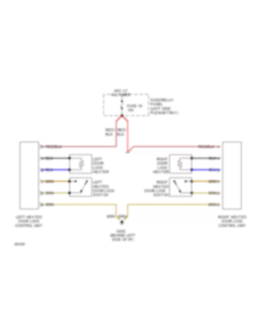
Heated Door Locks Wiring Diagram for Audi 90 S 1994
List of elements for Heated Door Locks Wiring Diagram for Audi 90 S 1994:
- All times
- Door lock
- Fuse 19 10a
- Fuse/relay panel (left side plenum tray)
- G202 (behind left side of i/p)
- Heated
- Heater
- Hot at
- Left door lock heater
- Left heated door lock control unit
- Left heated door lock switch
- Right
- Right door lock
- Right heated door lock control unit
- Switch
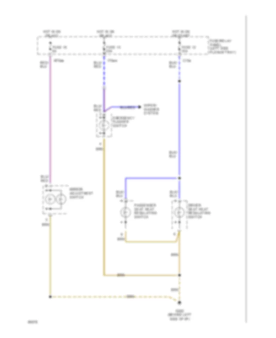
POWER MIRRORS
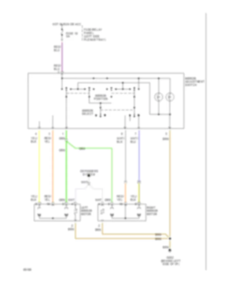
Power Mirrors Wiring Diagram for Audi 90 S 1994
List of elements for Power Mirrors Wiring Diagram for Audi 90 S 1994:
- Defoggers
- Fuse 18 5a
- Fuse/relay panel (left side plenum tray)
- G202 (behind left side of i/p)
- Hot in run or acc
- Left mirror motor
- Mirror adjustment switch
- Mirror position
- Mirror select
- Right mirror motor
- System
POWER SEATS
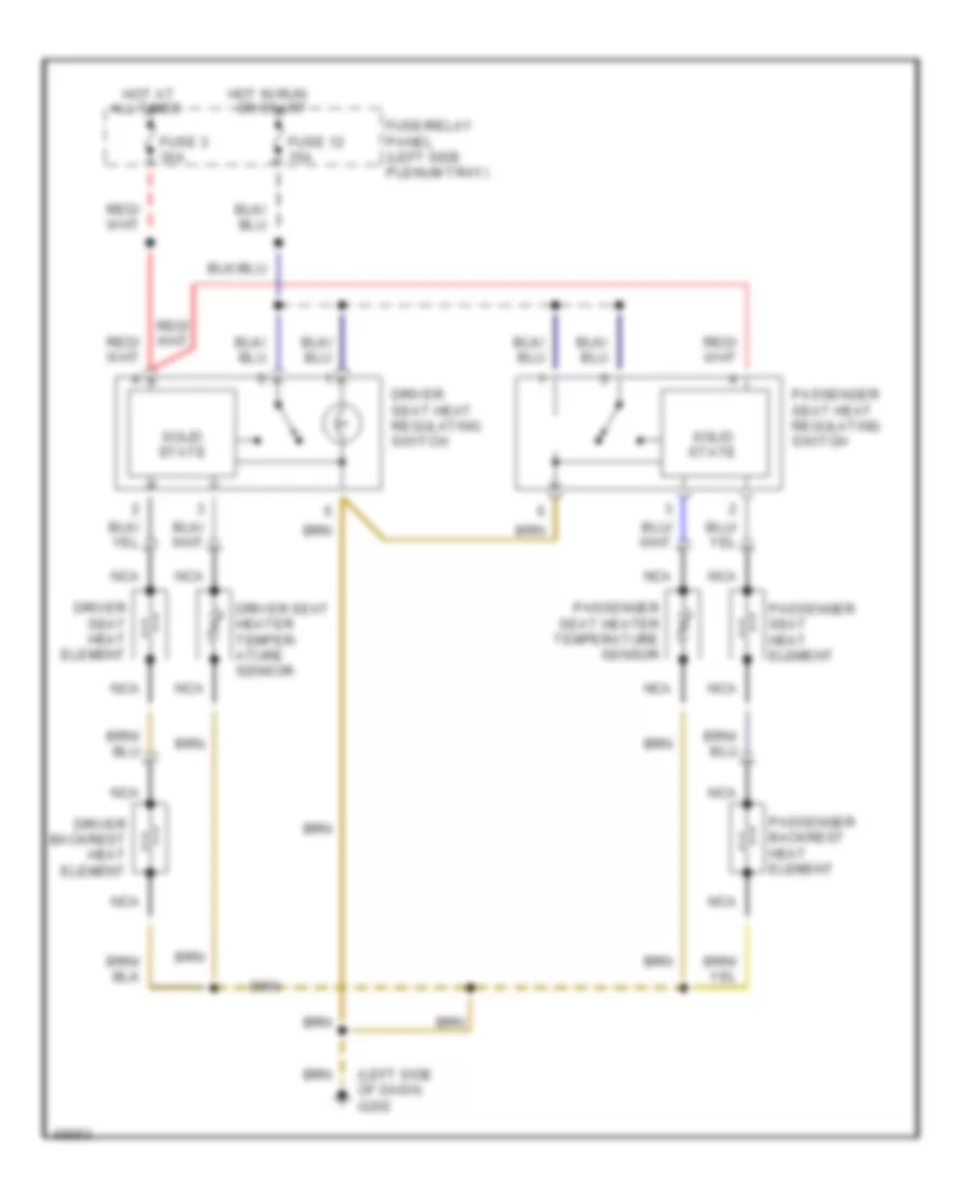
Heated Seats Wiring Diagram for Audi 90 S 1994
List of elements for Heated Seats Wiring Diagram for Audi 90 S 1994:
- (left side of dash) g202
- All times
- Driver backrest heat element
- Driver seat heat element
- Driver seat heat regulating switch
- Driver seat heater temper- ature sensor
- Fuse 12 15a
- Fuse 3 30a
- Fuse/relay panel (left side plenum tray)
- Hot at
- Hot in run or start
- Nca
- Passenger backrest heat element
- Passenger seat heat element
- Passenger seat heat regulating switch
- Passenger seat heater temperature sensor
- Solid state
Left Power Seat Wiring Diagram for Audi 90 S 1994
List of elements for Left Power Seat Wiring Diagram for Audi 90 S 1994:
- Back- rest
- Circuit breaker 44 30a
- Driver seat backrest adjusting motor
- Driver seat fore/aft adjusting motor
- Driver seat front height adjusting motor
- Driver seat rear height adjusting motor
- Driver seat switch
- Fore/ aft
- Front height
- Fuse/relay panel (left side plenum tray)
- G202 (behind left side of dash)
- Hot at all times
- Rear height
POWER TOP/SUNROOF
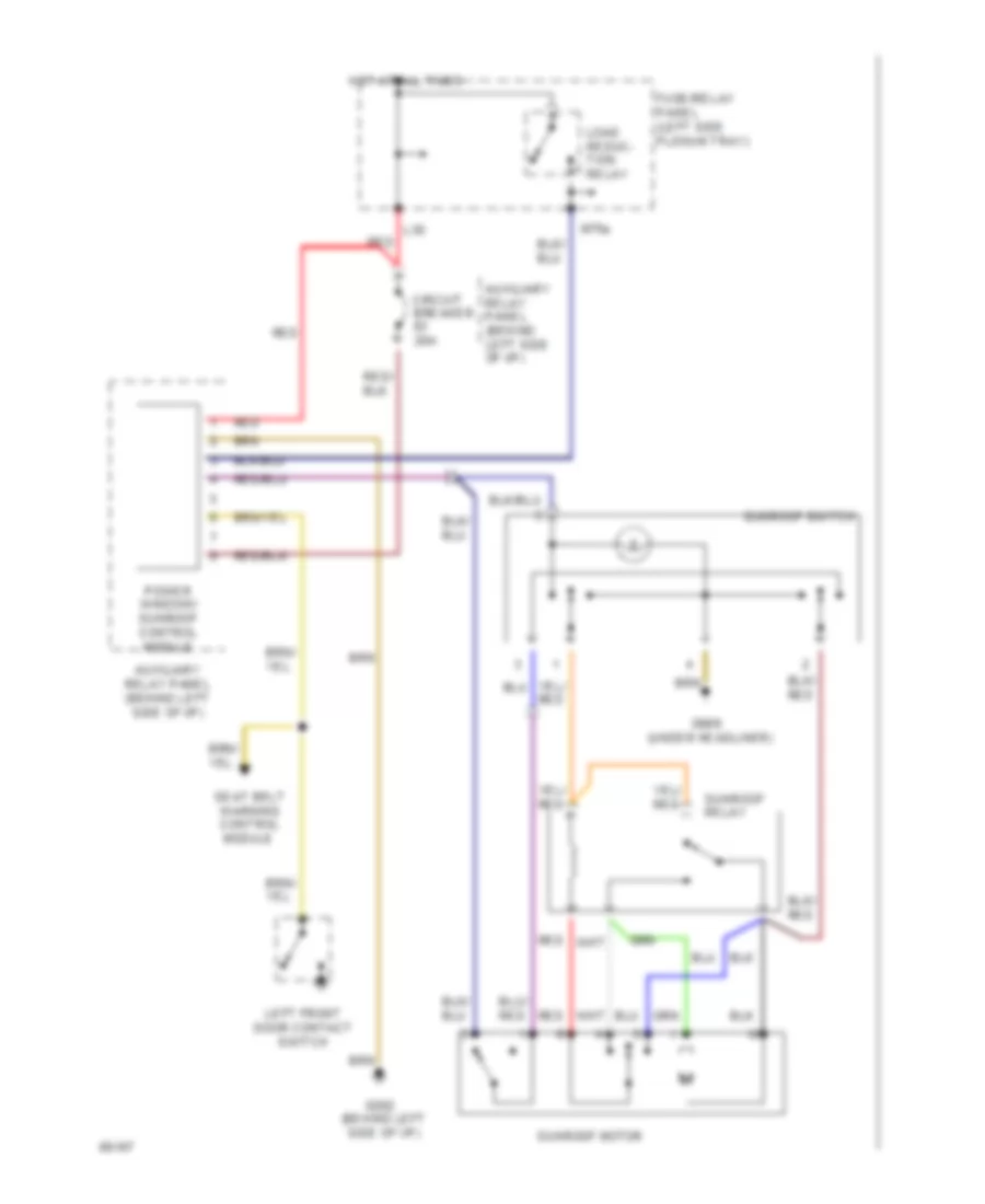
Sunroof Wiring Diagram for Audi 90 S 1994
List of elements for Sunroof Wiring Diagram for Audi 90 S 1994:
- Auxiliary relay panel (behind left side of i/p)
- Circuit breaker 20a
- Fuse/relay panel (left side plenum tray)
- G202 (behind left side of i/p)
- G908 (under headliner)
- Hot at all times
- Iii
- L30
- Left front door contact switch
- Load reduc- tion relay
- M75s
- Power window/ sunroof control module
- Red
- Seat belt warning control module
- Sunroof motor
- Sunroof relay
- Sunroof switch
POWER WINDOWS
Power Windows Wiring Diagram for Audi 90 S 1994
List of elements for Power Windows Wiring Diagram for Audi 90 S 1994:
-
-
- All times
- Auxiliary relay panel (behind left side of i/p)
- Circuit breaker 20a
- Fuse/relay panel (left side plenum tray)
- G202 (behind left side of i/p)
- Hot at
- Hot in on or acc
- Left front door contact switch
- Left front window motor
- Left front window switch
- Left rear
- Left rear door window motor
- Left rear window switch (door)
- Nca
- Power window control module
- Right front door contact switch
- Right front door window motor
- Right front window switch (center console)
- Right front window switch (door)
- Right rear
- Right rear door window motor
- Right rear window switch (door)
- Seat belt warning control module
- Sunroof motor
- Window lockout switch
- Window switch (center console)
RADIO
Radio Wiring Diagram for Audi 90 S 1994
List of elements for Radio Wiring Diagram for Audi 90 S 1994:
- 15a
- 86s
- Antenna
- Antenna amplifier (left rear "d" pillar)
- Antenna amplifier (right rear "d" pillar)
- Anti-theft system
- F30al
- Fuse 4
- Fuse/ relay panel
- G202 (behind left side of dash)
- Hot at all times
- Ignition switch
- Instrument cluster system
- Interior lights system
- Key in ignition
- Left front speaker
- Left rear tweeter
- Left rear woofer
- Mini check system control module
- Nca
- Radio
- Rear window defogger switch
- Rear window defogger/ window antenna
- Red
- Right front speaker
- Right rear tweeter
- Right rear woofer
- T10h
- T2af
- T2ag
- T5m
- T5n
- T8b
- T8c
SHIFT INTERLOCK
Shift Interlock Wiring Diagram for Audi 90 S 1994
List of elements for Shift Interlock Wiring Diagram for Audi 90 S 1994:
- (behind left side of i/p)
- (left kick panel)
- Alarm system/
- Auxiliary relay panel
- Auxiliary relay panel (behind left side of i/p)
- Back-up
- Brake light switch
- C/1
- C/9
- Central locking/
- Cluster
- Control module
- Engine control module
- Function switch
- Fuse 12 15a
- Fuse 29 10a
- Fuse/relay panel (left side plenum tray)
- G200 (lower left "a" pillar)
- Hot at all times
- Hot in on or acc
- Instrument
- Interior light delay
- Lights
- Multi-
- Park/ neutral position relay
- Shift lock
- Shift lock control module
- Solenoid
- Speedometer
- Starting
- System
- Transmission control module
- Vehicle speed output
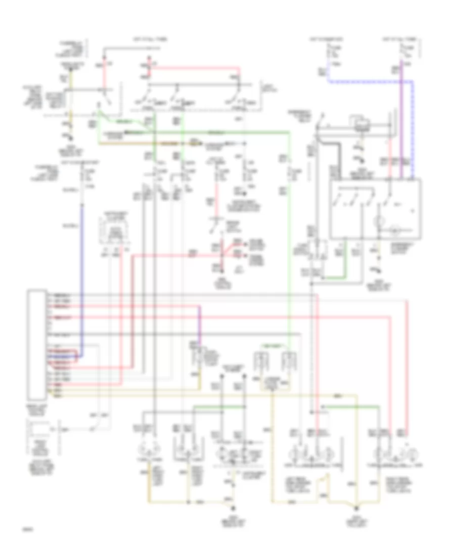
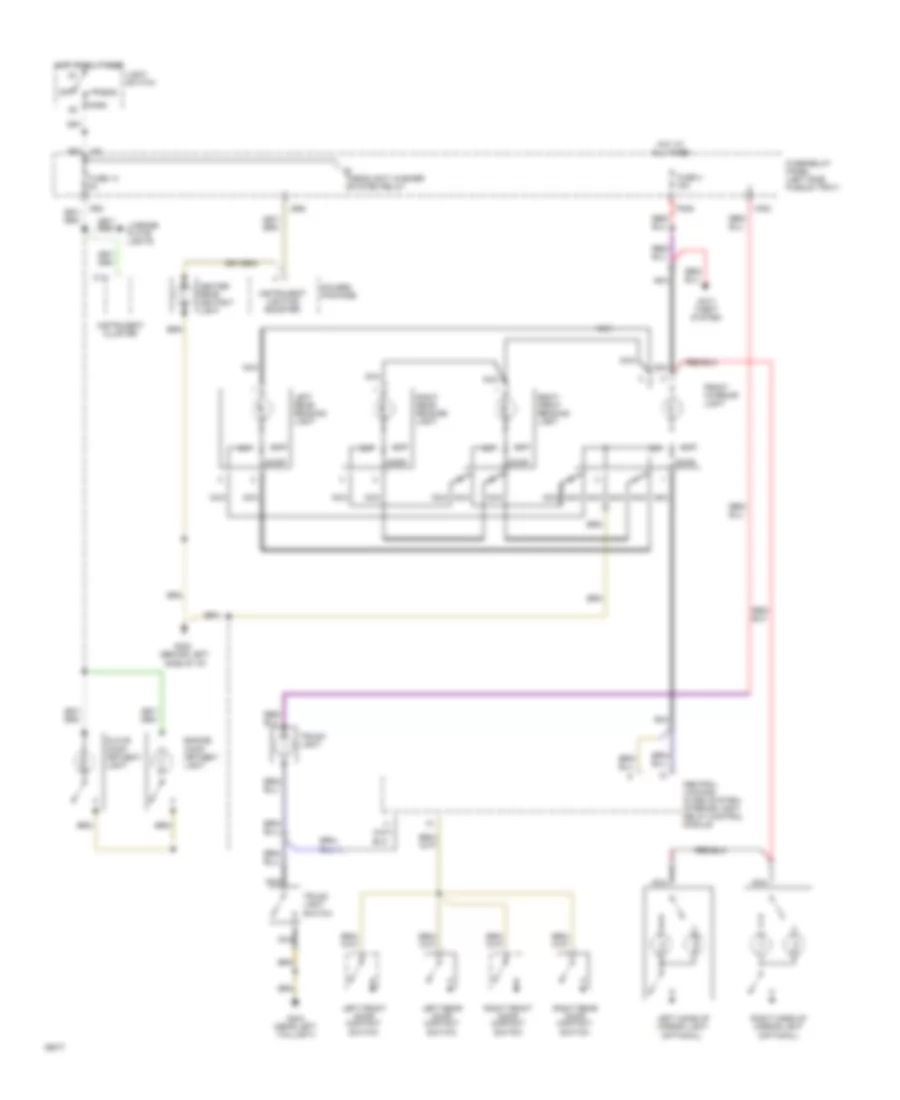
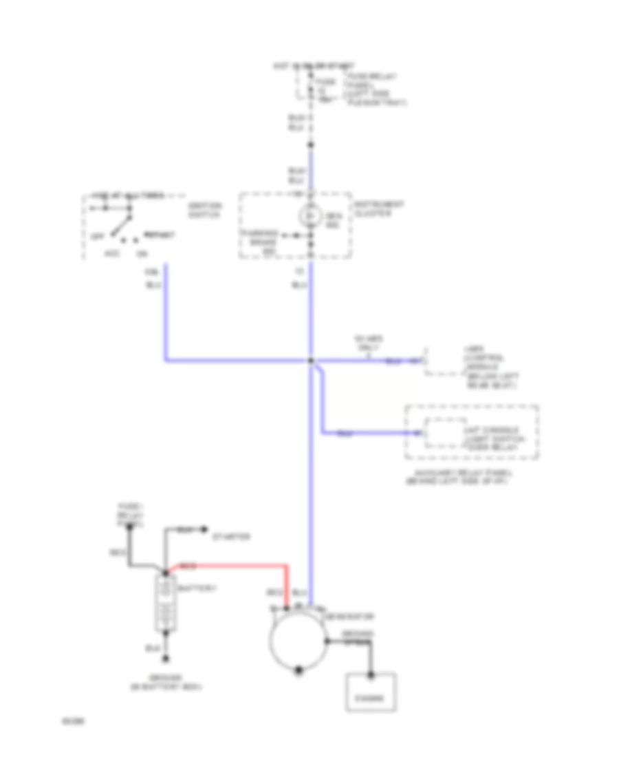
STARTING/CHARGING
Starter System Wiring Diagram (Cabriolet Wiring Diagram A/T) for Audi 90 S 1994
List of elements for Starter System Wiring Diagram (Cabriolet Wiring Diagram A/T) for Audi 90 S 1994:
- (behind left side of i/p)
- (left kick panel)
- (not used)
- 15a
- Acc
- Alarm system/
- Auxiliary relay panel
- Back-up lights
- Battery
- C/1
- C/9
- Central locking/
- Central locking/ alarm system/ interior light delay control module
- Control module
- E50a
- Engine control module (between right front of bulkhead & air duct)
- Function switch
- Fuse/relay panel
- Fuse/relay panel (left side plenum tray)
- G202 (behind left side of i/p)
- Generator
- Ground (in battery box)
- Hot at all times
- Ignition switch
- Interior light delay
- Multi-
- Off
- Park/ neutral position relay
- Red
- Shift lock control module (in auxiliary relay panel, left kick panel)
- Start
- Starter
- Transmission control module
Starter System Wiring Diagram (Cabriolet Wiring Diagram M/T) for Audi 90 S 1994
List of elements for Starter System Wiring Diagram (Cabriolet Wiring Diagram M/T) for Audi 90 S 1994:
- (not used)
- 15a
- Acc
- Alarm system relay
- Battery
- Bridge connection (w/o alarm system)
- C/1
- Central locking/ alarm system/ interior light delay control module
- E50a
- F50z
- Fuse/ relay panel (left side plenum tray)
- Generator
- Ground (in battery box)
- H50w
- Ignition switch
- L30
- L30 red
- Off
- Red
- Start
- Starter
Charging Wiring Diagram for Audi 90 S 1994
List of elements for Charging Wiring Diagram for Audi 90 S 1994:
- (behind left side of i/p)
- (below left rear seat)
- 50b
- A/t console light switch- over relay
- Abs control module
- Acc
- Auxiliary relay panel
- Battery
- Engine
- Fuse 15a
- Fuse/ relay panel
- Fuse/relay panel (left side plenum tray)
- Gen ind.
- Generator
- Ground (in battery box)
- Ground strap
- Hot at all times
- Hot in on or start
- Ignition switch
- Instrument cluster
- Off
- Parking brake ind.
- Red
- Start
- Starter
- W/ abs only
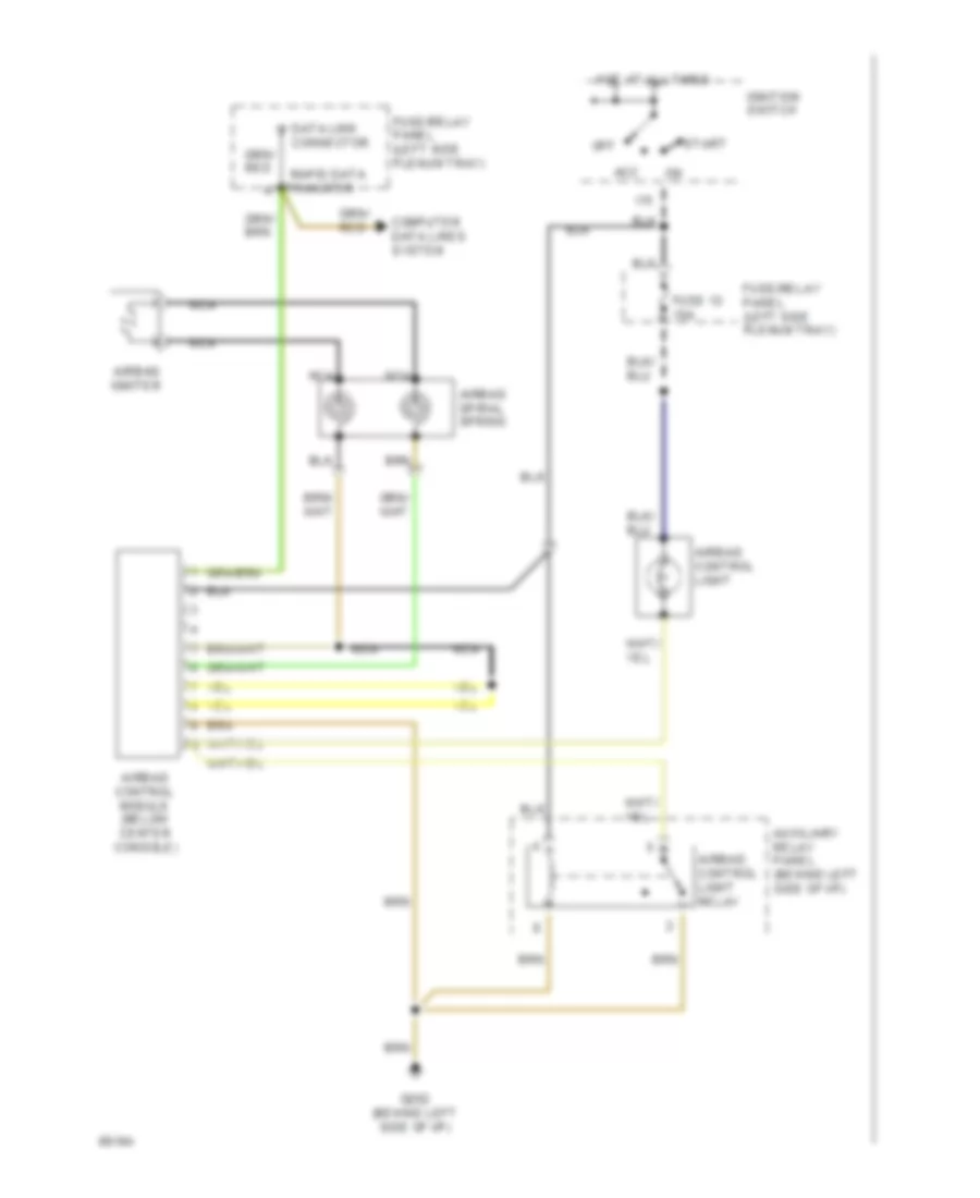
SUPPLEMENTAL RESTRAINTS
Supplemental Restraints Wiring Diagram for Audi 90 S 1994
List of elements for Supplemental Restraints Wiring Diagram for Audi 90 S 1994:
-
-
- Acc
- Airbag control light
- Airbag control light relay
- Airbag control module (below center console)
- Airbag igniter
- Airbag spiral spring
- Auxiliary relay panel (behind left side of i/p)
- Computer data lines system
- Connector
- Data link
- Fuse 12 15a
- Fuse/relay panel (left side plenum tray)
- G202 (behind left side of i/p)
- Hot at all times
- I15
- Ignition switch
- Nca
- Off
- Rapid data
- Start
- Transfer
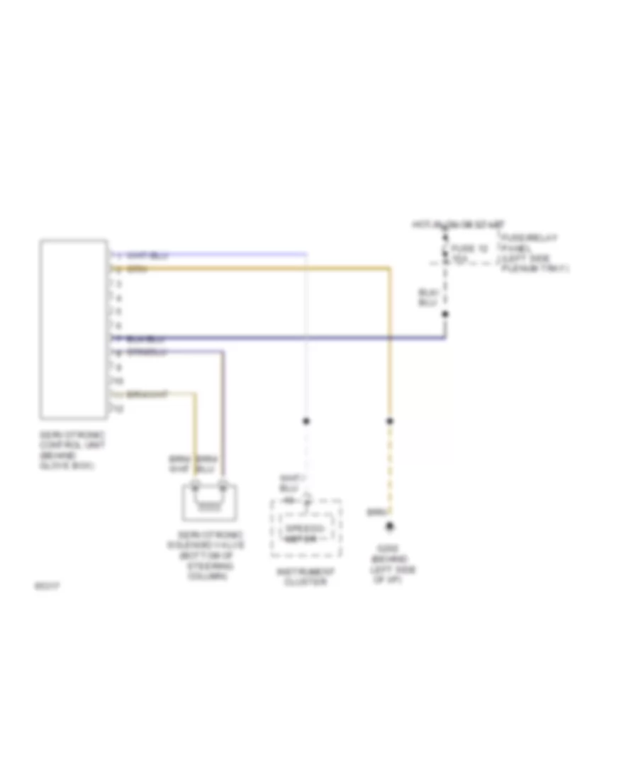
TRANSMISSION
A/T Wiring Diagram for Audi 90 S 1994
List of elements for A/T Wiring Diagram for Audi 90 S 1994:
- (left side of i/p)
- * 1993 models
- 1995 vftc c
- 2p n
- 50a
- 50z
- 87a
- A/c kickdn
- A/c system
- Abs/tcs
- Atf temp
- Automatic transmission console light
- Automatic transmission console light switch-over relay
- Auxilliary relay panel (left i/p)
- Brake light switch (on pedal cluster)
- Brake lt sw
- C15a
- Central locking/ alarm system/ interior light delay control module (below right taillight)
- Cruise control system
- Data link connector (in plenum tray)
- E50a
- Engine control module (between front right of bulkhead and air duct)
- Exterior lights system
- F30al
- F50z
- Fuse 10a
- Fuse 15a
- Fuse 5a
- Fuse/ relay panel (left side plenum tray)
- G131 (on intake manifold)
- G202 (left side of i/p)
- Gear selection indicator
- Generator terminal d+
- Ground
- H50w
- Hot at all times
- Hot in on or start
- Ign time adj
- Ignition switch terminal 50 (hot in start)
- Interior lights system
- K wire diag
- Kick-down switch (on throttle housing)
- Kickdn sw
- L30
- M-f switch
- Multi- function switch (rear of gear box housing)
- Not
- On/start v
- P/n
- Park/ neutral position relay
- Pk/neut sig
- Program switch light relay
- Protection diode
- R n
- Red
- Red/ starter terminal
- Rpm sig
- Shift interlock system
- Shift lock control module
- Sol supp v
- Solenoid 1
- Solenoid 2
- Solenoid 3
- Solenoid 4
- Solenoid 5
- Solenoid 6
- Solenoid 7
- Solenoid valves
- Spd ctrl mod
- T20
- Tps signal v
- Tr display
- Tr prog sw
- Tr sw lamp
- Transmission control module (on brake pedal support)
- Transmission fluid temperature sensor
- Transmission range program switch
- Used
- Valve body
- Vehicle speed sensor (on gearbox housing)
- Vss
Differential Lock Wiring Diagram, Quattro for Audi 90 S 1994
List of elements for Differential Lock Wiring Diagram, Quattro for Audi 90 S 1994:
- (behind left side of i/p)
- Cluster
- Diff. lock ind.
- Differ- ential lock switch
- Differential lock control
- Electronic differential lock cut- off relay
- Fuse 31 15a
- Fuse/relay panel (left side plenum tray)
- G202
- Hot in on or start
- Ill.
- Instrument
- Interior lights system (rheostat)
- Module
- Rear diff. lock ind.
- Rear differential lock switch
- Rear differential lock switch illumination/ indicator
- Solid state
- Speedo- meter
WARNING SYSTEMS
Warning Systems Wiring Diagram, with Mini-Check System for Audi 90 S 1994
List of elements for Warning Systems Wiring Diagram, with Mini-Check System for Audi 90 S 1994:
- (0.3 bar)
- (behind left side of i/p)
- 5/1
- 5/2
- 5/3
- 5/4
- 5/5
- 6/1
- 6/2
- 6/3
- 6/4
- 6/5
- 6/6
- 86s
- A/c system
- Acc
- Antenna amplifier
- Anti- theft system
- Auxiliary relay panel (behind left side of i/p)
- B10
- B15a
- Back-up lights
- C1-1
- C1-10
- C1-11
- C1-13
- C1-19
- C1-4
- C1-5
- C1-8
- C15a
- C2-15
- C2-16
- C2-18
- C2-21
- C3-10
- C3-12
- C3-13
- C3-14
- C3-3
- C3-4
- C3-7
- C3-8
- C3-9
- Cruise control system
- Dimmer switch
- Ect electronic thermoswitch
- Engine control module
- Engine coolant level switch
- Engine oil pressure switch
- F30al
- Fuel gauge
- Fuel gauge damper control module
- Fuel level sensor
- Fuse 12 15a
- Fuse 14 5a
- Fuse 4 15a
- Fuse/ relay panel (left side plenum tray)
- Fuse/relay panel (left side plenum tray)
- G202
- G404 (near left taillight)
- Generator
- Head
- Hot at all times
- Hot in on or start
- Hot w/ park or headlights on
- I58d
- Ignition switch
- Instrument cluster system
- Instrument panel lights
- Key-in ignition
- Left front door contact switch
- Left seat belt switch
- Light switch
- Mini- check system control module
- Mini-check system
- Nca
- Off
- Park
- Power window control module
- Quattro only
- Radio
- Red
- Start
- Voltage stabilizer
Warning Systems Wiring Diagram, without Mini-Check System for Audi 90 S 1994
List of elements for Warning Systems Wiring Diagram, without Mini-Check System for Audi 90 S 1994:
-
-
- (behind left side of i/p)
- 86a
- Acc
- Alarm system/
- Antenna amplifier
- Auxiliary relay panel
- Central locking/
- Control module
- Exterior
- Fuse 12 15a
- Fuse/relay panel (left side plenum tray)
- G202 (behind left side of i/p)
- Head
- Hot at all times
- Hot in on or start
- Ignition switch
- Instrument cluster
- Interior light delay
- Key-in- ignition
- L30
- Left front door contact switch
- Left seat belt switch
- Light
- Lights system
- Nca
- Off
- Park
- Power window control module
- Radio
- Red
- Seat belt ind.
- Seat belt warning system relay
- Start
- Switch
WIPER/WASHER
Wiper/Washer Wiring Diagram for Audi 90 S 1994
List of elements for Wiper/Washer Wiring Diagram for Audi 90 S 1994:
- B53c
- C31b
- C53c
- C53e
- Emergency
- Engine compartment light
- Flasher switch
- Fuse 15 25a
- Fuse/relay panel (left side plenum tray)
- G202 (behind left side of i/p)
- G31
- Headlight washer pump
- Headlight washer system relay
- Hot at all times
- Hot in on or acc
- Hot w/ park or headlights on
- Instrument cluster system
- J75ah
- Left washer nozzle heater (optional)
- Nca
- Red
- Right washer nozzle heater (optional)
- Solid state
- Washer fluid level switch
- Washer switch
- Windshield washer pump
- Windshield wiper intermittent switch
- Windshield wiper motor
- Wiper switch
- Wiper/ washer inter- mittent relay

 Čeština
 Dansk
Dansk Deutsch
 Ελληνικά
 English
 English
 Español
 Suomi
Suomi Français
 עברית
עברית Hrvatski
 Magyar
 Italiano
 日本語
日本語 한국어
한국어 Nederlands
 Polski
 Português
 Português
 Română
 Русский
 Slovenčina
 Slovenščina
 Svenska
 Türkçe
 中文 (中国)