AIR CONDITIONING
Compressor Wiring Diagram for Chevrolet HHR SS 2009
 https://portal-diagnostov.com/license.html
Automotive Electricians Portal FZCO
Automotive Electricians Portal FZCO
https://portal-diagnostov.com/license.html
https://portal-diagnostov.com/license.html
Automotive Electricians Portal FZCO
Automotive Electricians Portal FZCO
List of elements for Compressor Wiring Diagram for Chevrolet HHR SS 2009:
- (2.0l: right rear of engine) (2.4l: right side of engine, near rear of exhaust manifold) (2.2l: top right rear of engine) engine coolant temperature (ect) sensor
- (not used)
- (or 2700)
- (or 5514)
- (or tan)
- 2.0l
- 5 volt ref
- A/c clutch relay 15
- A/c compressor clutch (lower left front of engine)
- A/c fuse 22 10a
- A/c refrigerant pressure sensor (on a/c line, near compressor)
- A/c req sig
- A/c request indicator
- A/c request sig
- A/c request switch
- Batt
- Body control module (bcm) (under center dash, below radio, on right side of center console)
- Computer data lines system
- D12 c1
- Diode a/c clutch diode 9
- Ect sig
- Engine control module (ecm) (left side of engine compt, in front of underhood fuse block)
- Except 2.0l
- F10
- F11 x2
- G109 (on left front shock tower)
- G203 (behind left end of dash)
- Gnd
- Hot at all times
- Hot w/ pwr/trn relay 26 energized
- Hot w/ run/crank relay 51 energized
- Hvac control assembly
- Hvac/ i/p ign fuse 16 10a
- Hvac/pk3 fuse 10 10a
- Ign 1 voltage
- J114 (early production)
- J115 (late production) (in engine harness)
- Logic
- Low ref
- Pnk
- Power distribution system
- Press sens sig
- Rly ctrl
- S101
- S200
- Serial data
- Serial data +
- Serial data -
- Tan
- Underhood fuse block (in engine compt, next to left strut tower)
- X1 d3
- X3 c5
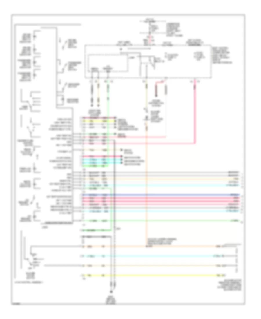
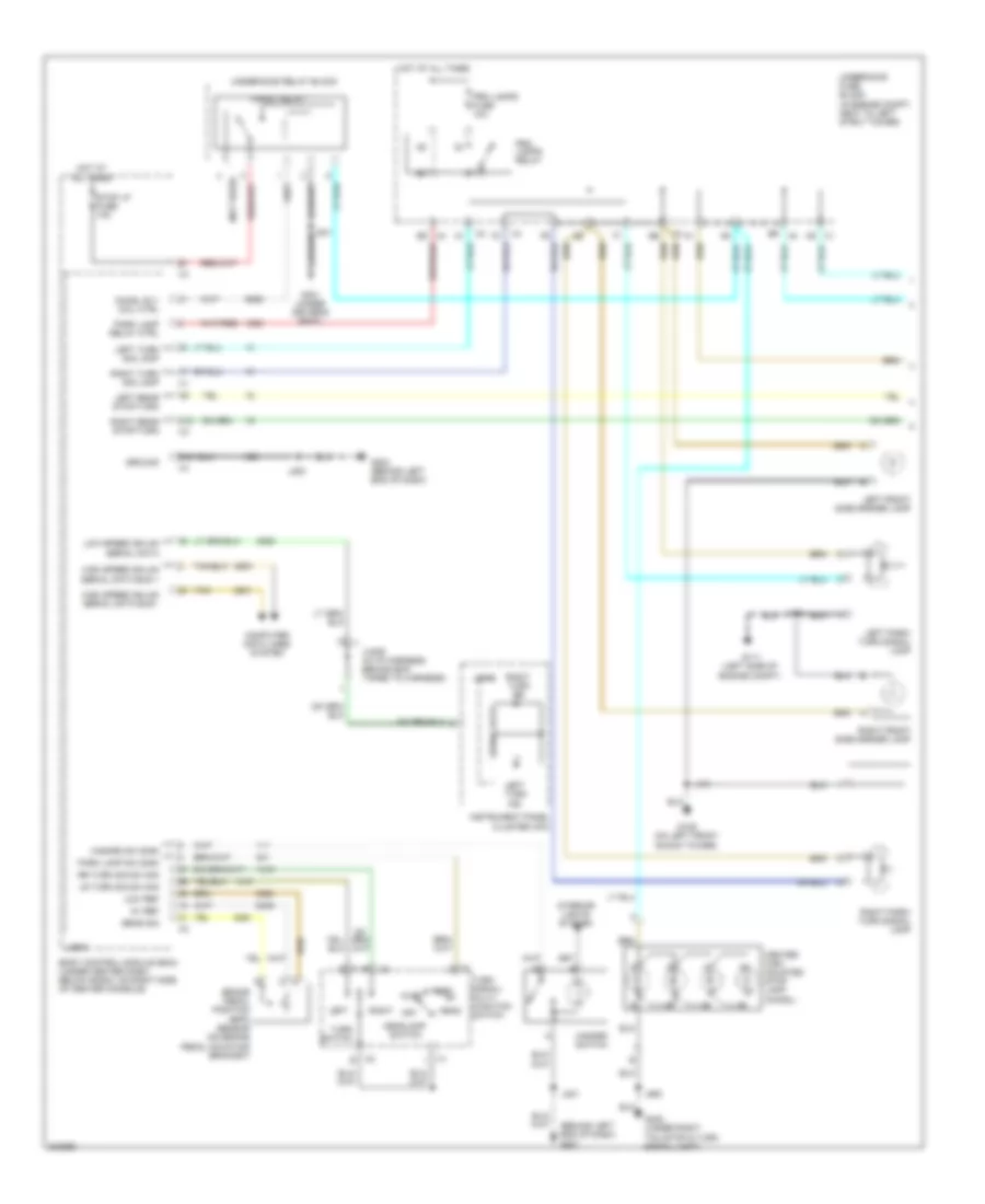
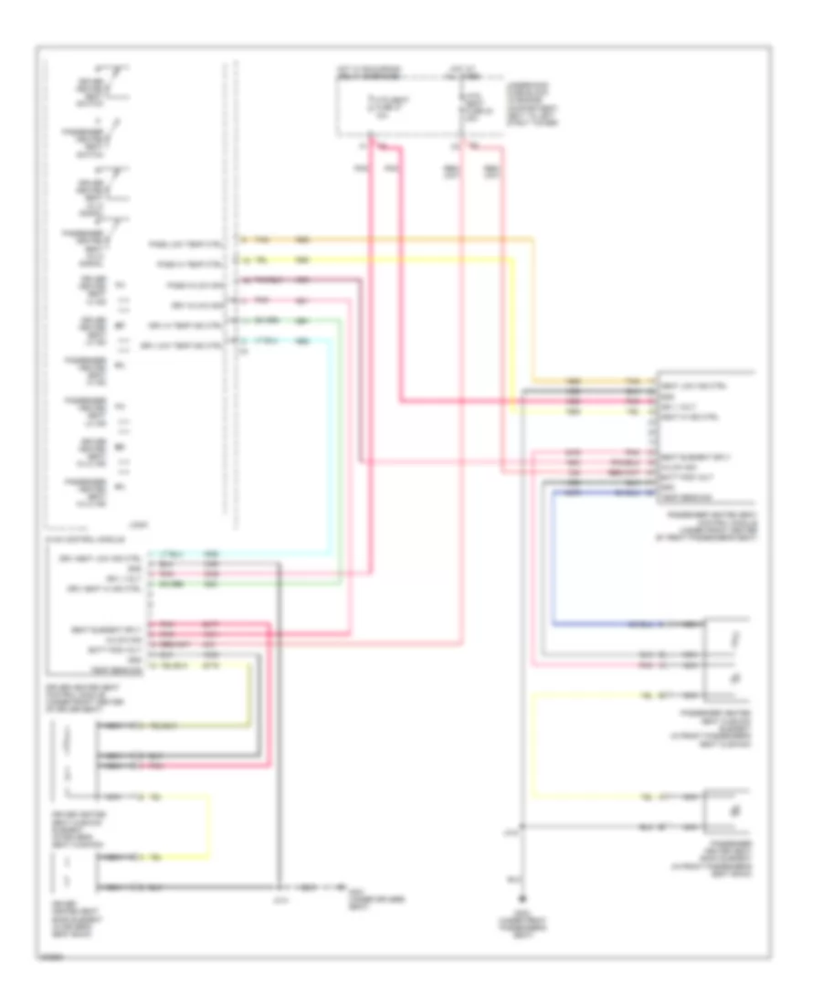
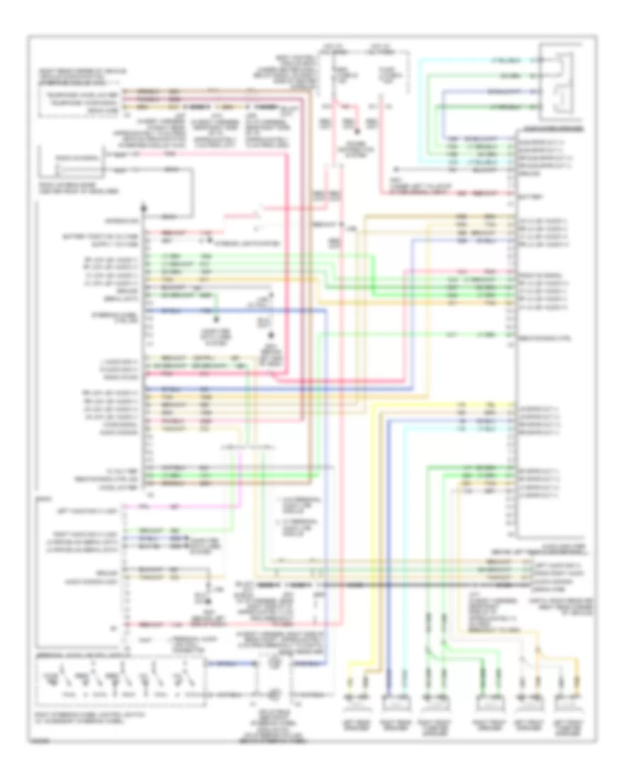
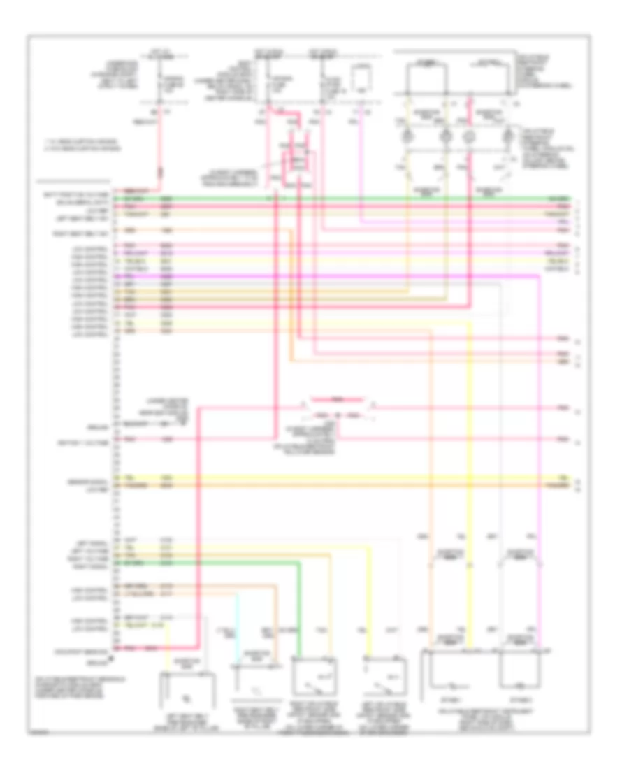
Manual A/C Wiring Diagram (1 of 2) for Chevrolet HHR SS 2009
List of elements for Manual A/C Wiring Diagram (1 of 2) for Chevrolet HHR SS 2009:
- (in hvac jumper harness, approximately 4.9 cm from blower motor) j203
- (not used)
- 5 volt ref
- A/c request indicator
- A/c request sig
- A/c request switch
- Air temp door ctrl
- Air temp door pos sig
- Battery positive
- Bcm 3 fuse 4 30a
- Blower motor (under right side of dash)
- Blower motor resistor assembly (under right side of dash, forward of blower motor)
- Blower motor switch
- Body control module (bcm) (under center dash, below radio, on right side of center console)
- Computer data lines system
- Defogger indicator
- Defogger switch
- Defogger system
- Dimmer switch sig
- Door ctrl
- Driver heated seat hi indicator
- Driver heated seat lo indicator
- Driver heated seat switch
- Fresh air indicator
- G203 (behind left end of dash)
- Gnd
- Hi/low signal
- High
- High temp ctrl
- High temp ind
- High/low sig
- Hot at all times
- Hot w/ run/ crank relay 51 energized
- Htd seat lo
- Hvac control assembly
- Hvac relay 30
- Hvac/ i/p ign fuse 16 10a
- Hvac/pk3 fuse 10 10a
- Ign 1 voltage
- J200
- Logic
- Low
- Low temp ind
- Mode door position sig
- Mode switch
- Off
- Passenger heated seat hi indicator
- Passenger heated seat lo indicator
- Passenger heated seat switch
- Pnk
- Power distribution system
- R defog relay ctrl
- R defog switch sig
- Recir door ctrl a
- Recir door ctrl b
- Recir- culation indicator
- Recir- culation switch
- Seats system
- Seats system interior lights system
- Serial data
- Tan
- Temperature control switch
- Underhood fuse block (in engine compt, next to left strut tower)
- Wake up volt off
- X2 f6
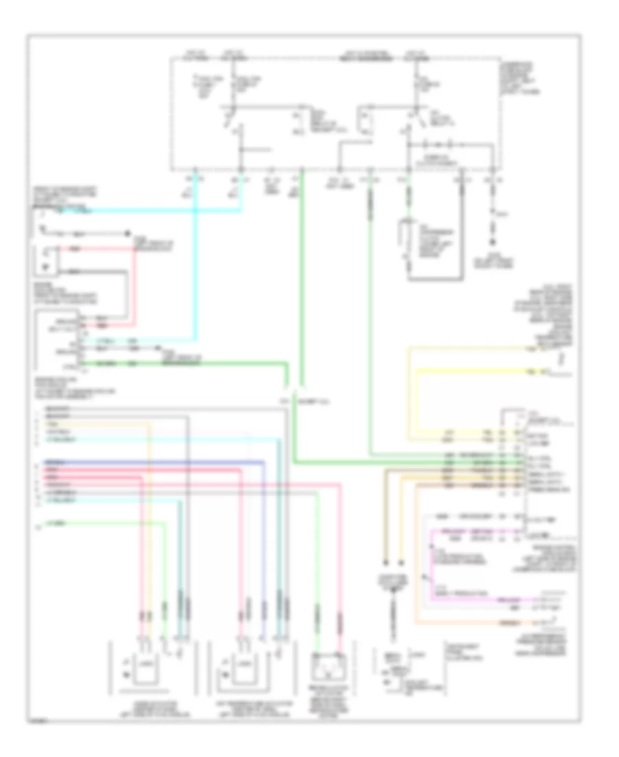
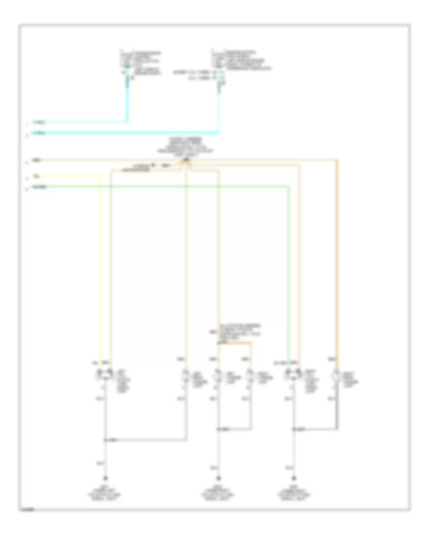
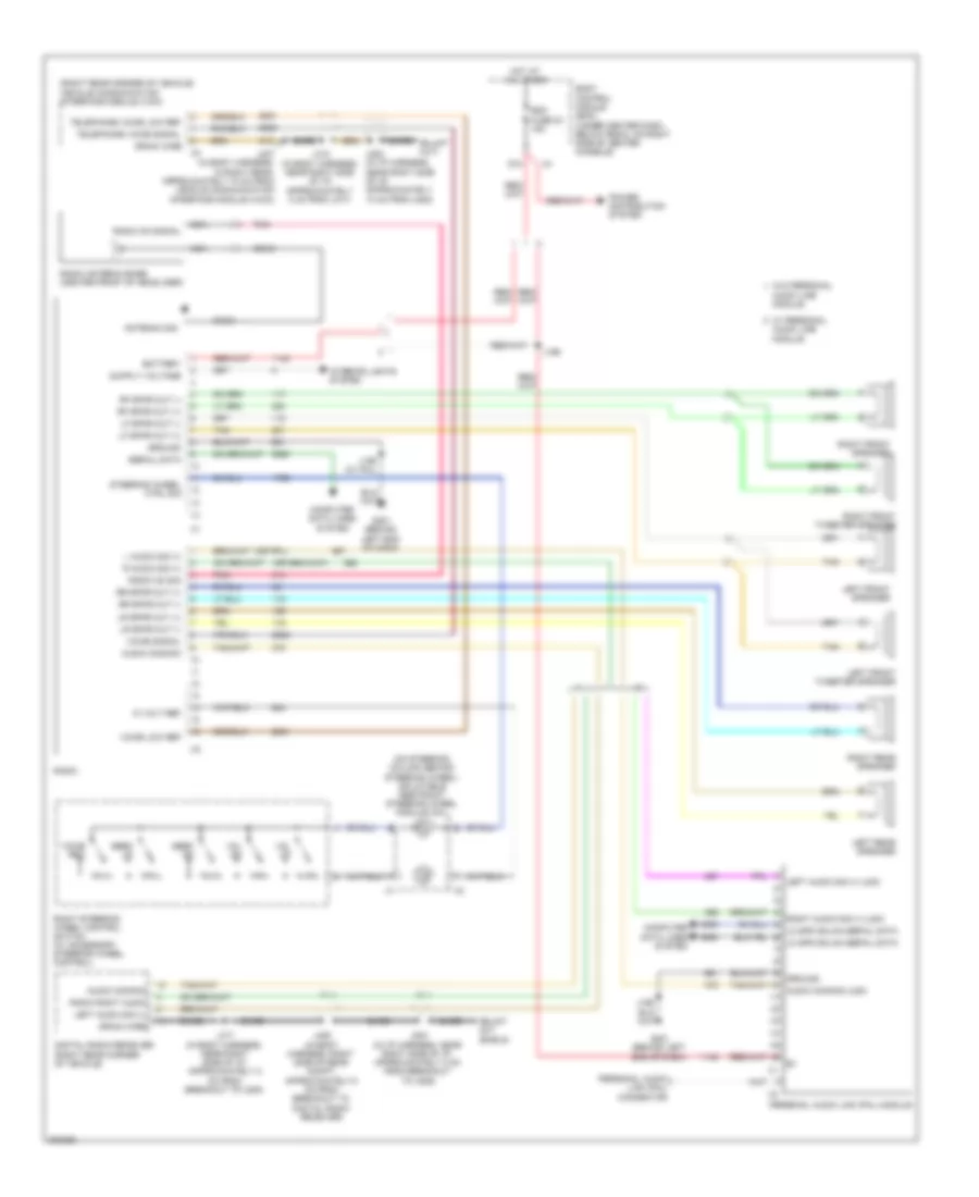
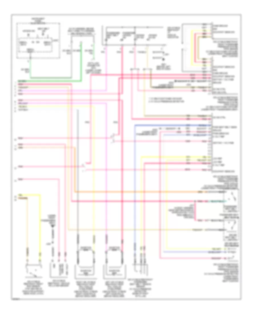
Manual A/C Wiring Diagram (2 of 2) for Chevrolet HHR SS 2009
List of elements for Manual A/C Wiring Diagram (2 of 2) for Chevrolet HHR SS 2009:
- (2.0l: right rear of engine) (2.4l: right side of engine, near rear of exhaust manifold) (2.2l: top right rear of engine) engine coolant temperature (ect) sensor
- (front of engine compt, attached to radiator) (except 2.0l) engine cooling fan
- (not used)
- (or 2700)
- (or 5514)
- (or tan)
- 2.0l
- 5 volt ref
- A/c clutch relay 15
- A/c compressor clutch (lower left front of engine)
- A/c fuse 22 10a
- A/c refrigerant pressure sensor (on a/c line, near compressor)
- Air temperature actuator (center of dash, left side of hvac module)
- Computer data lines system
- Cool fan fuse 40 30a
- Cool fan fuse 7 (2.0l) 40a
- Cool fan relay 50 (except 2.0l)
- Coolant temperature ind
- Ctrl
- D12 x1
- D3 x1
- Diode a/c clutch diode 9
- Ect sig
- Engine control module (ecm) (left side of engine compt, in front of underhood fuse block)
- Engine cooling fan (front of engine compt, attached to radiator)
- Engine cooling fan module (attached to engine cooling fan motor assembly)
- Except 2.0l
- F10
- F11 x2
- G105 (left front of engine block)
- G109 (on left front shock tower)
- Ground
- Hot at all times
- Hot w/ pwr/trn relay 26 energized
- Ign
- Instrument panel cluster (ipc)
- J114 (early production)
- J115 (late production) (in engine harness)
- Logic
- Low ref
- Mode actuator (center of dash, left side of hvac module)
- Pnk
- Press sens sig
- Recirculation actuator (behind right side of dash, above blower motor)
- Red
- Rly ctrl
- S101
- Serial data
- Serial data +
- Serial data -
- Splt volt
- Tan
- Underhood fuse block (in engine compt, next to left strut tower)
- X1 b2
- X2 a5
- X3 c5
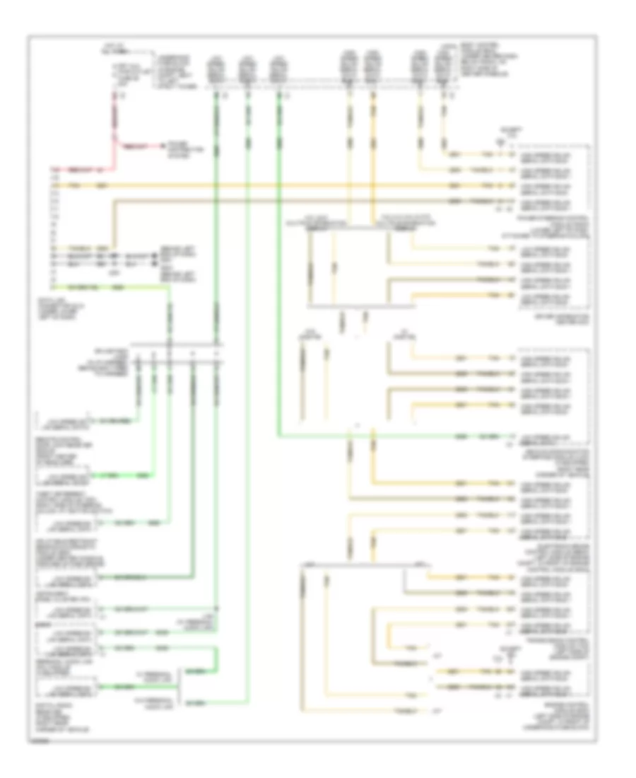
ANTI-LOCK BRAKES
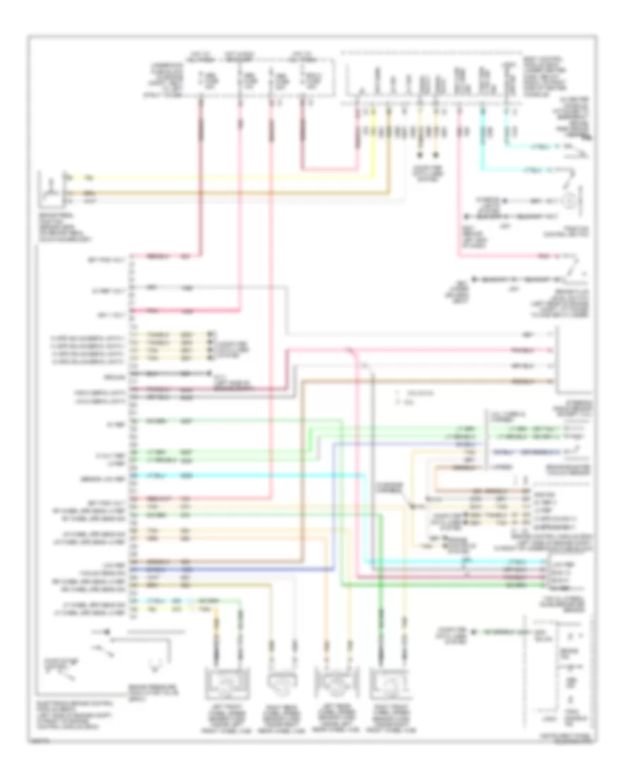
Anti-lock Brakes Wiring Diagram, with Active Brake Control for Chevrolet HHR SS 2009
List of elements for Anti-lock Brakes Wiring Diagram, with Active Brake Control for Chevrolet HHR SS 2009:
- (in center console, attached to emergency brake) park brake switch
- (in engine harness)
- (or tan)
- 2.0l
- 2.0l turbo & 5 speed
- 2.2l & 2.4l
- 4 speed
- 5 v ref
- 5 volt ref
- 5v ref
- 5v ref 3
- 5v ref volt
- Abs fuse 10a
- Abs fuse 20a
- Abs fuse 40a
- Abs ind
- Bat pos volt
- Bcm 2 fuse 40a
- Body control module (bcm) (under center dash, below radio, on right side of center console)
- Bpp sens
- Brake booster vacuum sensor
- Brake fluid level switch (left rear of engine compt, attached to master cylinder)
- Brake ind
- Brake pedal position sensor (bpp) (on brake pedal mounting bracket)
- Brake pressure modulator valve (bpmv)
- Brk fluid lvl sens sig
- Bus hi
- Bus lo
- Computer data lines system
- D12
- Data + serial
- Data - serial
- Electronic brake control module (ebcm) (left side of engine compt, in front of engine control module (ecm))
- Engine control module (ecm) (left side of engine compt, in front of underhood fuse block)
- Engine controls system
- G111 (left side of engine compt)
- G201 (behind left end of dash)
- G301 (under driver's seat)
- Ground
- Hi spd glman (+)
- Hi spd glman (-)
- Hi spd gmlan serial data +
- Hi spd gmlan serial data -
- High 2 serial data
- Hot at all times
- Hot in run or start
- Ign 1 volt
- Instrument panel cluster (ipc)
- J114
- J115
- J201
- J301
- Left front wheel speed sensor (wss) (inside left front wheel hub)
- Left rear wheel speed sensor (wss) (inside left rear wheel hub)
- Lf wheel spd sens lo ref
- Lf wheel spd sens sig
- Lo ref
- Logic
- Low 2 serial data
- Low ref
- Lr wheel spd sens lo ref
- Lr wheel spd sens sig
- Nca
- Park brk sw sig
- Pnk
- Pump motor control
- Rf wheel spd sens lo ref
- Rf wheel spd sens sig
- Right front wheel speed sensor (wss) (inside right front wheel hub)
- Right rear wheel speed sensor (wss) (inside right rear wheel hub)
- Rr wheel spd sens lo ref
- Rr wheel spd sens sig
- Sensor low ref
- Sns sig
- Spd gmlan
- Steering angle sensor (except 2.0l)
- Tan
- Trac disable ind
- Traction control switch
- Traction ctrl sw sig
- Underhood fuse block (in engine compt, next to left strut tower)
- Vacuum sens sig
- Yaw & lateral accelerometer sensor
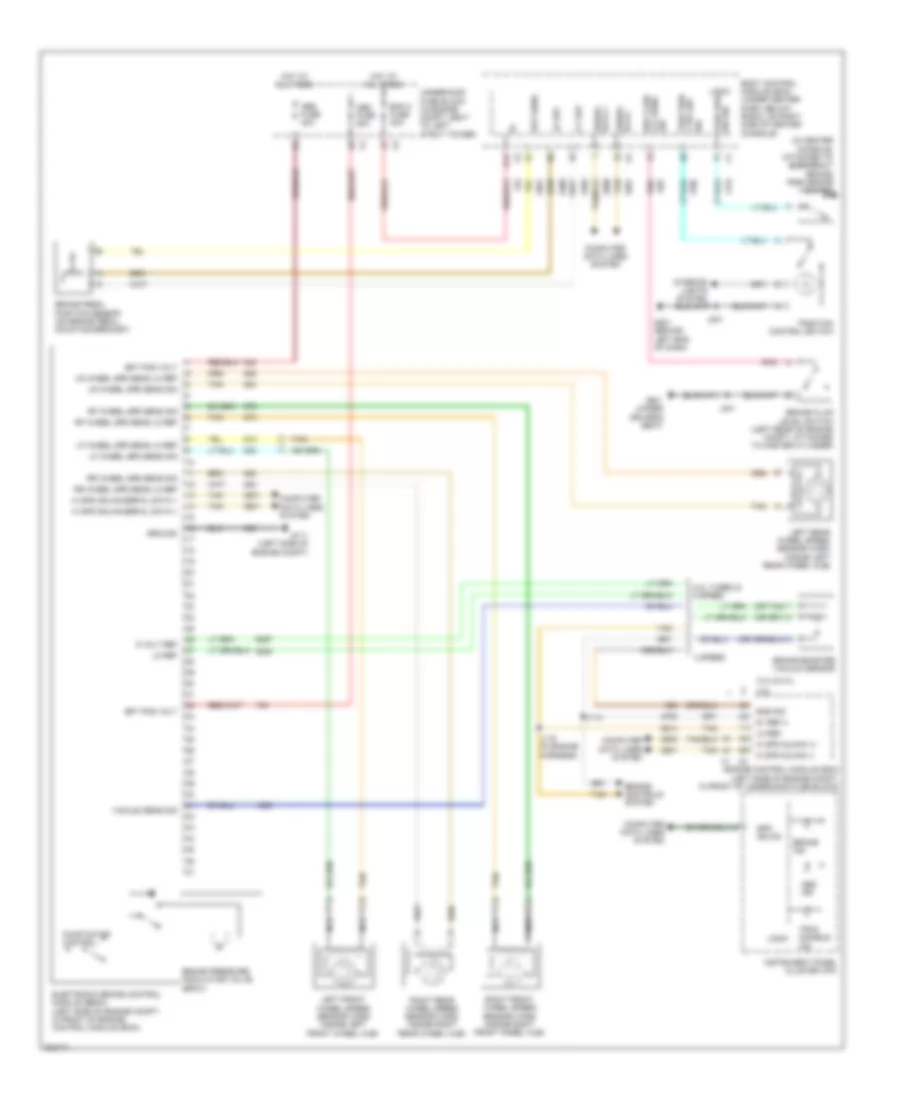
Anti-lock Brakes Wiring Diagram, without Active Brake Control for Chevrolet HHR SS 2009
List of elements for Anti-lock Brakes Wiring Diagram, without Active Brake Control for Chevrolet HHR SS 2009:
- (in center console, attached to emergency brake) park brake switch
- (or tan)
- 2.0l
- 2.0l turbo & 5 speed
- 2.2l & 2.4l
- 4 speed
- 5 v ref
- 5 volt ref
- 5v ref 3
- Abs fuse 20a
- Abs fuse 40a
- Abs ind
- Bat pos volt
- Bcm 2 fuse 40a
- Body control module (bcm) (under center dash, below radio, on right side of center console)
- Bpp sens
- Brake booster vacuum sensor
- Brake fluid level switch (left rear of engine compt, attached to master cylinder)
- Brake ind
- Brake pedal position sensor (on brake pedal mounting bracket)
- Brake pressure modulator valve (bpmv)
- Computer data lines system
- Ctrl sw traction
- D12
- Electronic brake control module (ebcm) (left side of engine compt, in front of engine control module (ecm))
- Engine control module (ecm) (left side of engine compt, in front of underhood fuse block)
- Engine controls system
- G111 (left side of engine compt)
- G201 (behind left end of dash)
- G301 (under driver's seat)
- Ground
- Hi spd glman (+)
- Hi spd glman (-)
- Hi spd gmlan serial data +
- Hot at all times
- Instrument panel cluster (ipc)
- J114
- J115 (in engine harness)
- J201
- J301
- Left front wheel speed sensor (wss) (inside left front wheel hub)
- Left rear wheel speed sensor (wss) (inside left rear wheel hub)
- Lf wheel spd sens lo ref
- Lf wheel spd sens sig
- Lo ref
- Logic
- Lr wheel spd sens lo ref
- Lr wheel spd sens sig
- Lvl sens brk fluid
- Nca
- Pnk
- Pump motor control
- Rf wheel spd sens lo ref
- Rf wheel spd sens sig
- Right front wheel speed sensor (wss) (inside right front wheel hub)
- Right rear wheel speed sensor (wss) (inside right rear wheel hub)
- Rr wheel spd sens lo ref
- Rr wheel spd sens sig
- Serial data +
- Serial data -
- Sig
- Sns sig
- Spd gmlan
- Sw sig park brk
- Tan
- Trac disable ind
- Traction control switch
- Underhood fuse block (in engine compt, next to left strut tower)
- Vacuum sens sig
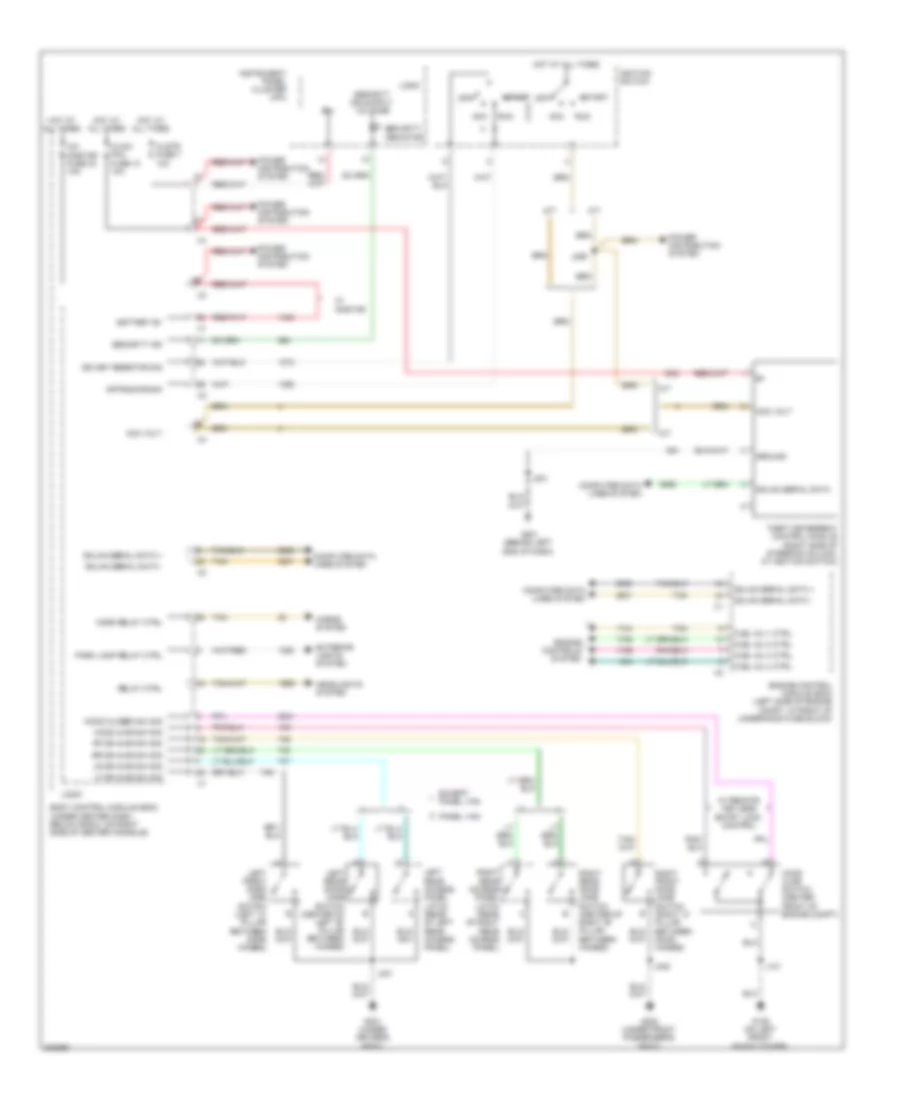
ANTI-THEFT
Anti-theft Wiring Diagram for Chevrolet HHR SS 2009
List of elements for Anti-theft Wiring Diagram for Chevrolet HHR SS 2009:
- A/t
- Acc
- Acc volt
- B(+)
- Battery b+
- Body control module (bcm) (under center dash, below radio, on right side of center console)
- Clstr fuse 7 10a
- Computer data lines system
- Engine control module (ecm) (left side of engine compt, in front of underhood fuse block)
- Engine controls system
- Except panel van
- Exterior lights system
- Fuel inj 1 ctrl
- Fuel inj 2 ctrl
- Fuel inj 3 ctrl
- Fuel inj 4 ctrl
- G109 (on left front shock tower)
- G201 (behind left end of dash)
- G301 (under driver's seat)
- G302 (under front passenger's seat)
- Gmlan serial data
- Gmlan serial data +
- Gmlan serial data -
- Ground
- Headlights system
- Hood ajar sw sig
- Hood ajar switch (center front of engine compt)
- Hood closed sw sig
- Horn relay ctrl
- Horns system
- Hot at all times
- Hvac/ pk3 fuse 10 10a
- Ign key resistor sig
- Ignition switch
- Instrument panel cluster (ipc)
- J101
- J201
- J206
- J301
- J302
- Left front door jamb switch (left "a" pillar between door hinges)
- Left rear access panel latch (rear of left rear access panel)
- Left rear door jamb switch (center of left "b" pillar between hinges)
- Lf dr ajar sw sig
- Logic
- Lr dr ajar sw sig
- M/t
- Off
- Off/run/crank
- Panel van
- Park lamp relay ctrl
- Power distribution system
- Relay ctrl
- Rf dr ajar sw sig
- Right front door jamb switch (right "a" pillar between door hinges)
- Right rear access panel latch (rear of right rear access panel)
- Right rear door jamb switch (center of right "b" pillar between hinges)
- Rr dr ajar sw sig
- Run
- Security ind
- Security indicator
- Start
- Tan
- Theft deterrent control module (right side of steering column, at ignition switch)
- W/ onstar
- W/ remote keyless entry lock control
- Xm/ onstar fuse 24 10a
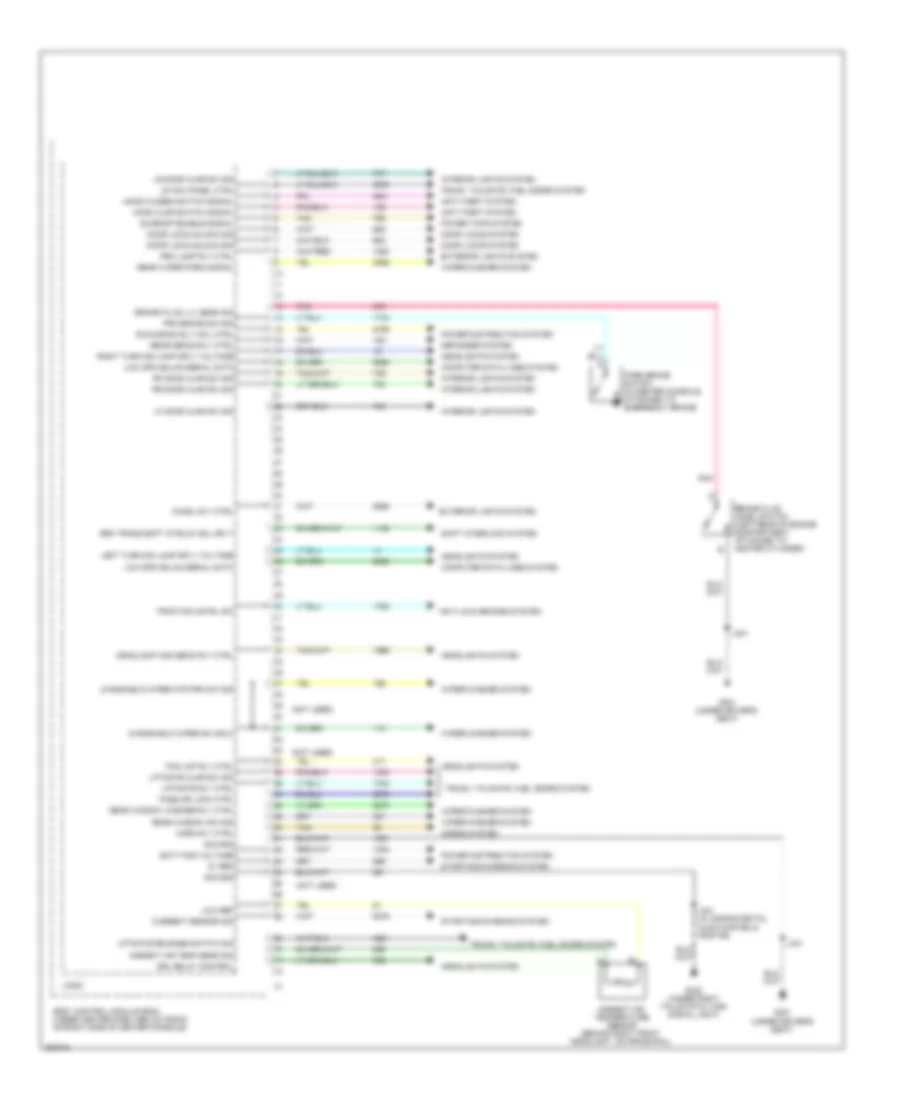
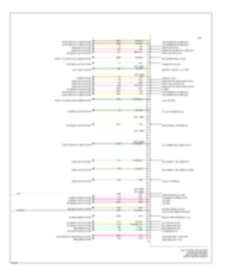
BODY CONTROL MODULES
Body Control Modules Wiring Diagram (1 of 4) for Chevrolet HHR SS 2009
List of elements for Body Control Modules Wiring Diagram (1 of 4) for Chevrolet HHR SS 2009:
- (not used)
- 5v ref
- Ambient air temp sens sig
- Ambient air temperature sensor (behind right front headlight, on frame rail)
- Anti-lock brakes system
- Anti-theft system
- Batt pos voltage
- Body control module (bcm) (under center dash, below radio, on right side of center console)
- Brake fluid level switch (left rear of engine compartment, attached to master cylinder)
- Brake fluid lvl sens sig
- Brk trans shft intrlck sol sply
- Chmsl rly ctrl
- Computer data lines system
- Current sensor sig
- Defogger system
- Door lock/unlock sig
- Door locks system
- Drl relay control
- Exterior lights system
- Fog lmp rly ctrl
- G301 (under driver's seat)
- G402 (under right tail/stop & turn signal light)
- Headlamp high beam rly ctrl
- Headlights system
- Hood ajar switch signal
- Hood closed switch signal
- Horn rly ctrl
- Horns system
- Interior lights system
- J301
- J401 (w/ s-band digital audio system & onstar)
- Left turn sig lamp sply voltage
- Lf door ajar sw sig
- Liftgate ajar sw sig
- Liftgate release switch sig
- Liftgate rly ctrl
- Logic
- Low ref
- Low spd gmlan serial data
- Lr acc panel ctrl
- Lr door ajar sw sig
- Park brake switch (in center console, attached to emergency brake)
- Pass dr lock ctrl
- Pnk
- Power distribution system
- Power tops system
- Prk brake sw sig
- Prk lamp rly ctrl
- Rear defog rly ctrl
- Rear window sw sig
- Rear window washer rly ctrl
- Rear wiper park signal
- Rf door ajar sw sig
- Right turn sig lamp sply voltage
- Rr door ajar sw sig
- Run/crank rly coil ctrl
- Shift interlock system
- Sig gnd
- Starting/charging system
- Sunroof enable signal
- Tan
- Traction cntrl sw
- Trunk, tailgate, fuel doors system
- Windshield wiper mtr prk sw sig
- Windshield wiper sw sig 2
- Wiper/washer system
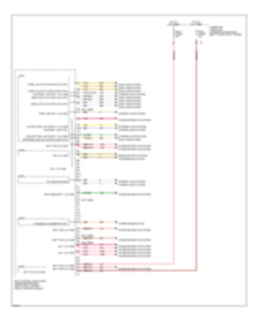
Body Control Modules Wiring Diagram (2 of 4) for Chevrolet HHR SS 2009
List of elements for Body Control Modules Wiring Diagram (2 of 4) for Chevrolet HHR SS 2009:
- (not used)
- A10
- A11
- A12
- Acc voltage
- B10
- B11
- B12
- Batt pos voltage
- Bcm 2 fuse 6 40a
- Bcm 3 fuse 4 30a
- Body control module (bcm) (under center dash, below radio, on right side of center console)
- C10
- C11
- C12
- Courtesy lamp ctrl
- Courtesy lamp sply voltage
- D10
- D11
- D12
- Door lock actuator lock ctrl
- Door lock actuator unlock ctrl
- Door locks system
- Driver dr lock actuator unlock ctrl
- Engine controls system
- Exterior lights system
- Hot at all times
- I/p lamp dim sw sig
- Ign 1 voltage
- Interior lights system
- Logic
- Park lamp sply voltage
- Pnk
- Power distribution system
- Tan
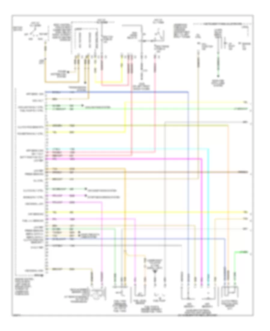
- Transmissions system
- Underhood fuse block (in engine compartment, next to left strut tower)
- Windshield washer pmp ctrl
- Wiper/washer system
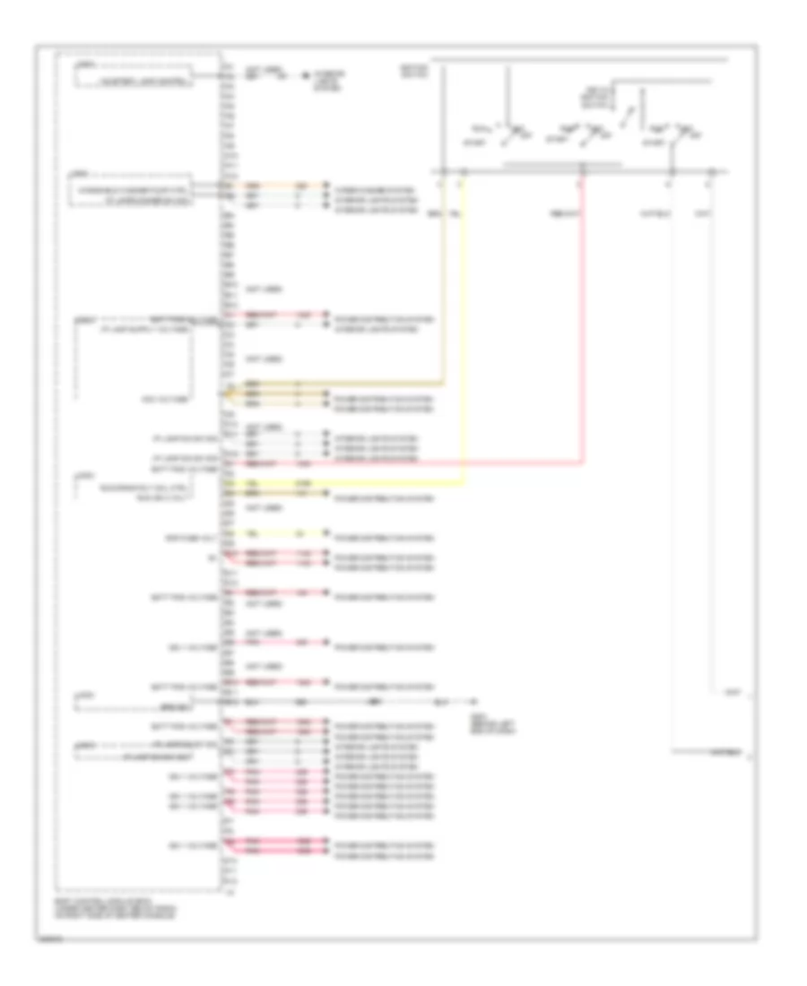
Body Control Modules Wiring Diagram (3 of 4) for Chevrolet HHR SS 2009
List of elements for Body Control Modules Wiring Diagram (3 of 4) for Chevrolet HHR SS 2009:
- (not used)
- A10
- A11
- A12
- Acc
- Acc voltage
- B10
- B11
- B12
- Batt pos voltage
- Body control module (bcm) (under center dash, below radio, on right side of center console)
- C10
- C11
- C12
- Courtesy lamp control
- D10
- D11
- D12
- E10
- E11
- E12
- F10
- F11
- F12
- G203 (behind left end of dash)
- Ground
- I/p lamp dim sw sig
- I/p lamps dimmer sw sig
- Ign 1 voltage
- Ignition switch
- Interior lights system
- J200
- Key-in ignition switch
- Logic
- Off
- Pnk
- Power distribution system
- Rap fuse volt
- Run
- Run ign 3 volt
- Run/crank rly coil ctrl
- Start
- Windshield washer pump ctrl
- Wiper/washer system
Body Control Modules Wiring Diagram (4 of 4) for Chevrolet HHR SS 2009
List of elements for Body Control Modules Wiring Diagram (4 of 4) for Chevrolet HHR SS 2009:
- (not used)
- 5v ref
- A/c request sig
- Air conditioning system
- Anti-theft system
- Body control module (bcm) (under center dash, below radio, on right side of center console)
- Brake pedal pos sens sig
- Computer data lines system
- Cruise control sw sig
- Cruise control system
- Defogger system
- Drl ambient light sens low ref
- Drl ambient light sens sig
- Exterior lights system
- Flash to pass sig
- Front fog lamp sw sig
- Hazard switch sig
- Headlamp dimmer sw hi beam sig
- Headlamp sw headlamps off sig
- Headlamp sw headlamps on sig
- Headlamp sw sig
- Headlights system
- High speed gmlan ser bus +
- High speed gmlan ser bus -
- Horn rly ctrl
- Horns system
- I/p lamp dimmer sw sig
- Ignition key resistor signal
- Interior lights system
- Lock control
- Logic
- Low ref
- Low speed gmlan serial data
- Lr turn sig sw sig
- Off/run/crank voltage
- Park lamp sw on sig
- Pass seat belt indicator
- Rear defog rly ctrl
- Rear defog sw sig
- Rear wiper/washer sw volt
- Rr access panel sw sig
- Rr turn sig sw sig
- Security ind sply voltage
- Tan
- Trunk, tailgate, fuel doors system
- Windshield wiper sw sig 1
- Wiper/washer system
COMPUTER DATA LINES
Computer Data Lines Wiring Diagram for Chevrolet HHR SS 2009
List of elements for Computer Data Lines Wiring Diagram for Chevrolet HHR SS 2009:
- (behind left end of dash) g201
- 2.0l
- 2.0l & w/ multiple information display
- 2.2l,2.4l,2.0l & w/o multiple information display
- A/t
- Body control logic
- Data link connector (dlc) (under lower left of dash)
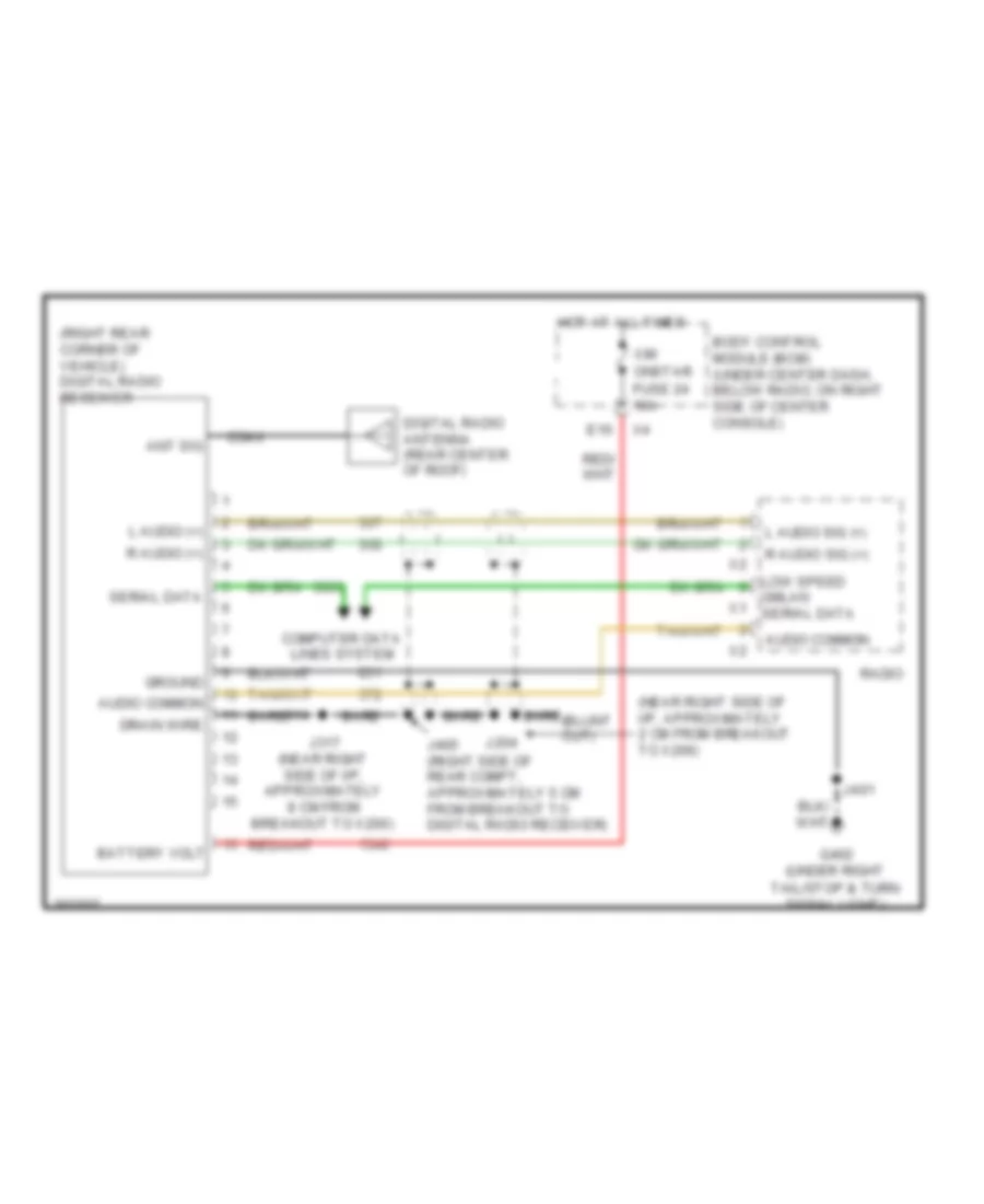
- Digital radio receiver (if equipped) (right rear corner of vehicle)
- Driver information center (dic)
- Electronic brake control module (ebcm) (left side of engine compt, in front of engine control module (ecm))
- Engine control module (ecm) (left side of engine compt, in front of underhood fuse block)
- Except 2.0l
- Frt aux pwr outlet fuse 29 20a
- G203 (behind left end of dash)
- High speed gmlan serial data bus +
- High speed gmlan serial data bus -
- Hot at all times
- Inflatable restraint sensing & diagnostic module (sdm) (under center console, forward of park brake)
- Instrument panel cluster (ipc)
- J194 (w/ personal audio link)
- J200
- J201
- Low speed gm lan serial data
- Low speed gmlan serial data
- Low speed gmlan serial data bus -
- M/t
- Module (bcm) (under center dash, below radio, on right side of center console)
- Personal audio link (pal) module (if equipped)
- Power distribution system
- Power steering control module (pscm) (lower left of dash, attached to steering column)
- Radio
- Remote control door lock receiver (rcdlr) (front center of headliner)
- Splice pack jx205 (in i/p harness, behind bcm taped to harness)
- Tan
- Theft deterrent control module (tdm) (right side of steering column, at ignition switch)
- Transmission control module (tcm) (left side of engine compt)
- Underhood fuse block (in engine compt, next to left strut tower)
- Vehicle communication interface module (vcim) (if equipped) (right rear corner of vehicle)
- W/ onstar
- W/ personal audio link
- W/o onstar
- W/o personal audio link
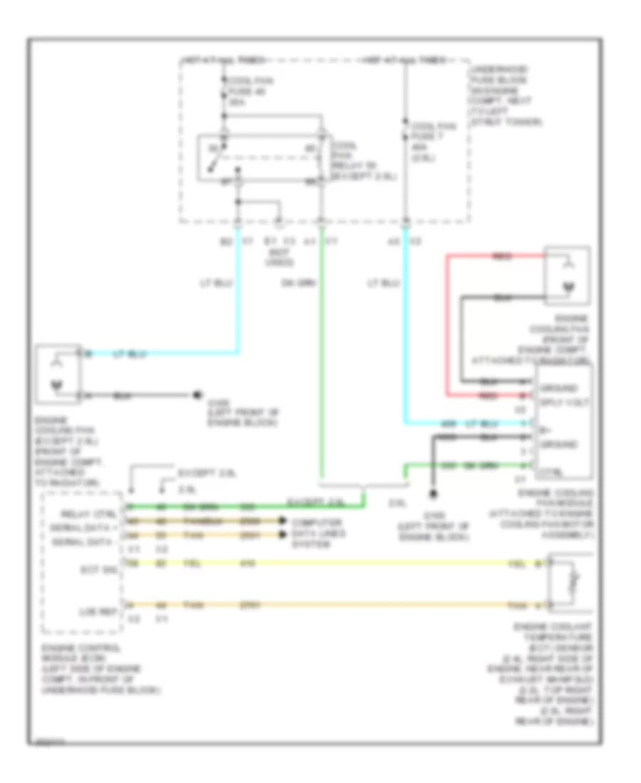
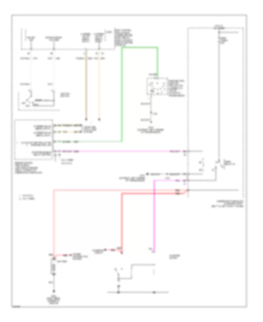
COOLING FAN
Cooling Fan Wiring Diagram for Chevrolet HHR SS 2009
List of elements for Cooling Fan Wiring Diagram for Chevrolet HHR SS 2009:
- (not used)
- 2.0l
- Computer data lines system
- Cool fan fuse 40 30a
- Cool fan fuse 7 40a (2.0l)
- Cool fan relay 50 (except 2.0l)
- Ctrl
- Ect sig
- Engine control module (ecm) (left side of engine compt, in front of underhood fuse block)
- Engine coolant temperature (ect) sensor (2.4l: right side of engine, near rear of exhaust manifold) (2.2l: top right rear of engine) (2.0l: right rear of engine)
- Engine cooling fan (except 2.0l) (front of engine compt, attached to radiator)
- Engine cooling fan (front of engine compt, attached to radiator)
- Engine cooling fan module (attached to engine cooling fan motor assembly)
- Except 2.0l
- G105 (left front of engine block)
- Ground
- Hot at all times
- Loe ref
- Red
- Relay ctrl
- Serial data +
- Serial data -
- Sply volt
- Tan
- Underhood fuse block (in engine compt, next to left strut tower)
- X1 a1
- X1 b2
- X2 a5
- X3 e1
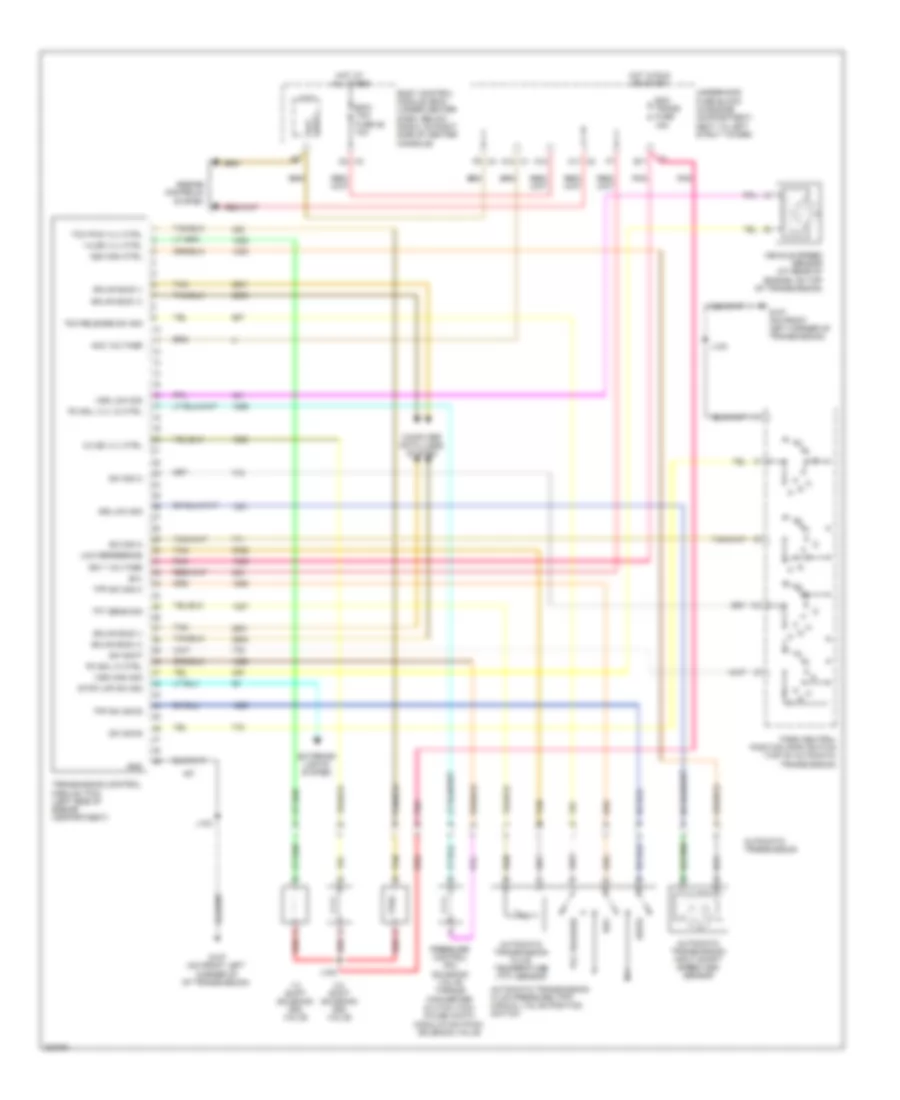
CRUISE CONTROL
Cruise Control Wiring Diagram for Chevrolet HHR SS 2009
List of elements for Cruise Control Wiring Diagram for Chevrolet HHR SS 2009:
- (in engine compt, next to left strut tower) underhood fuse block
- (not used)
- (on steering column, behind steering wheel) inflatable restraint steering wheel module coil
- (or 2709)
- (or 2759)
- (or 6354)
- (or 6356)
- (or tan)
- +5v
- 2.0l
- 2.2l/2.4l
- 5 volt ref
- 5v ref
- A/t
- A9 x1
- Accelerator pedal position (app) sensor (on accelerator pedal bracket)
- App sens 1 sig
- App sens 2 sig
- Body control module (bcm) (under center dash, below radio, on right side of center console)
- Brake pedal position sensor (on brake pedal mounting bracket)
- Brake pos sig
- Chmsl relay
- Clutch pedal position (cpp) sensor (m/t)
- Computer data lines system
- Cruise control on ind
- Cruise ctrl sw sig
- Engine control module (ecm) (left side of engine compt, in front of underhood fuse block)
- Engine controls system
- Eps/str whl cntrl fuse 19 2a
- Exterior lights system
- G201 (behind left end of dash)
- G301 (under driver's seat)
- Gmlan (+)
- Gmlan (-)
- Gnd
- Hot at all times
- Hot w/ run/ crnk relay energized
- J208 (w/ accessory steering wheel control)
- J211 (2.0l) (in body harness main bundle, approximately 15 cm rear of first breakout)
- J301
- Left steering wheel control switch
- Logic
- Low ref
- M/t
- Pnk
- Pos sens rtn
- Pos sens sig pos
- Pos sens sply
- Power distribution system
- Relay ctl
- Res+
- Set-
- Stop lamp sply volt
- Stop lp fuse 9 10a
- Tac mtr ctrl 1
- Tac mtr ctrl 2
- Tan
- Tan c
- Throttle actuator control (tac) module (2.2l: top of engine) (2.4l: top of intake manifold) (2.0l: on throttle body)
- Tp sens 1 sig
- Tp sens 2 sig
- Transmission control module (tcm) (left side of engine compt)
- Transmissions system
- Underhood relay block
- Vehicle speed sensor (at rear of engine, on top of transmission)
- Vss hi sig
- Vss high sig
- Vss lo sig
- Vss low sig
- X4 e1
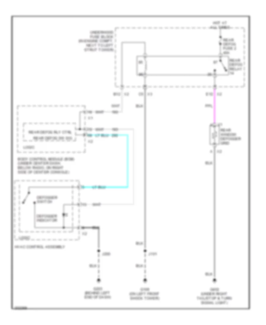
DEFOGGERS
Defoggers Wiring Diagram for Chevrolet HHR SS 2009
List of elements for Defoggers Wiring Diagram for Chevrolet HHR SS 2009:
- Body control module (bcm) (under center dash, below radio, on right side of center console)
- Defogger indicator
- Defogger switch
- G109 (on left front shock tower)
- G203 (behind left end of dash)
- G402 (under right tail/stop & turn signal light)
- Hot at all times
- Hvac control assembly
- J101
- J200
- Logic
- Rear defog fuse 2 40a
- Rear defog relay
- Rear defog rly ctrl
- Rear defog sw sig
- Rear window defogger grid
- Underhood fuse block (in engine compt, next to left strut tower)
- X2 a
- X2 b12
- X2 e12
- X3 c5
ELECTRONIC POWER STEERING
2.0L VIN X
2.0L VIN X, Electronic Power Steering Wiring Diagram for Chevrolet HHR SS 2009
List of elements for 2.0L VIN X, Electronic Power Steering Wiring Diagram for Chevrolet HHR SS 2009:
- Body control module (bcm) (under center dash, below radio, on right side of center console)
- Computer data lines system
- Cruise control system
- Electronic power steering (eps) motor (at base of steering column)
- Eps fuse 1 60a
- Eps/str whl cntrl fuse 19 2a
- Exciting gnd
- G109 (on left front shock tower)
- Gmlan +
- Gmlan -
- Gnd
- Hot at all times
- Hot in run or start
- Ign
- In shaft cos
- In shaft sn
- Motor resolver
- Mtr u phase
- Mtr v phase
- Mtr w phase
- Out shaft cos
- Out shaft sn
- Pnk
- Power steering control module (pscm) (lower left of dash, attached to steering column)
- Red
- Sens cos
- Sens exciting
- Sens sn
- Tan
- Tor sens excit
- Tor sens gnd
- Torque resolver
- Underhood fuse block (in engine compartment, next to left strut tower)
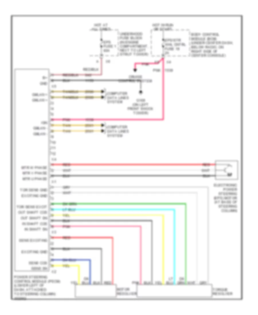
2.2L VIN B
2.2L VIN B, Electronic Power Steering Wiring Diagram for Chevrolet HHR SS 2009
List of elements for 2.2L VIN B, Electronic Power Steering Wiring Diagram for Chevrolet HHR SS 2009:
- B(+)
- Body control module (bcm) (under center dash, below radio, on right side of center console)
- Class 2 serial data
- Computer data lines system
- Cruise control system
- Driver information center (dic) display
- Electric power steering (eps) motor
- Eps fuse 1 60a
- Eps/str whl cntrl fuse 19 2a
- G109 (on left front shock tower)
- Ground
- Hot at all times
- Hot in run or start
- Ign 1 volt
- Instrument panel cluster (ipc)
- Left assist motor ctrl
- Logic
- Pnk
- Power steering control module (pscm)
- Red
- Right assist motor ctrl
- Steering column
- Steering shaft torque sensor
- Tan
- Tan/
- Underhood fuse block (in engine compartment, next to left strut tower)
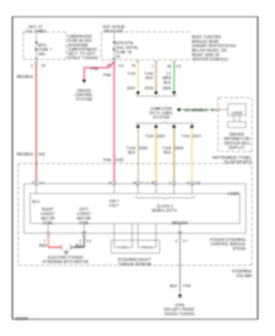
2.4L VIN V
2.4L VIN V, Electronic Power Steering Wiring Diagram for Chevrolet HHR SS 2009
List of elements for 2.4L VIN V, Electronic Power Steering Wiring Diagram for Chevrolet HHR SS 2009:
- B(+)
- Body control module (bcm) (under center dash, below radio, on right side of center console)
- Class 2 serial data
- Computer data lines system
- Cruise control system
- Driver information center (dic) display
- Electric power steering (eps) motor
- Eps fuse 1 60a
- Eps/str whl cntrl fuse 19 2a
- G109 (on left front shock tower)
- Ground
- Hot at all times
- Hot in run or start
- Ign 1 volt
- Instrument panel cluster (ipc)
- Left assist motor ctrl
- Logic
- Pnk
- Power steering control module (pscm)
- Red
- Right assist motor ctrl
- Steering column
- Steering shaft torque sensor
- Tan
- Tan/
- Underhood fuse block (in engine compartment, next to left strut tower)
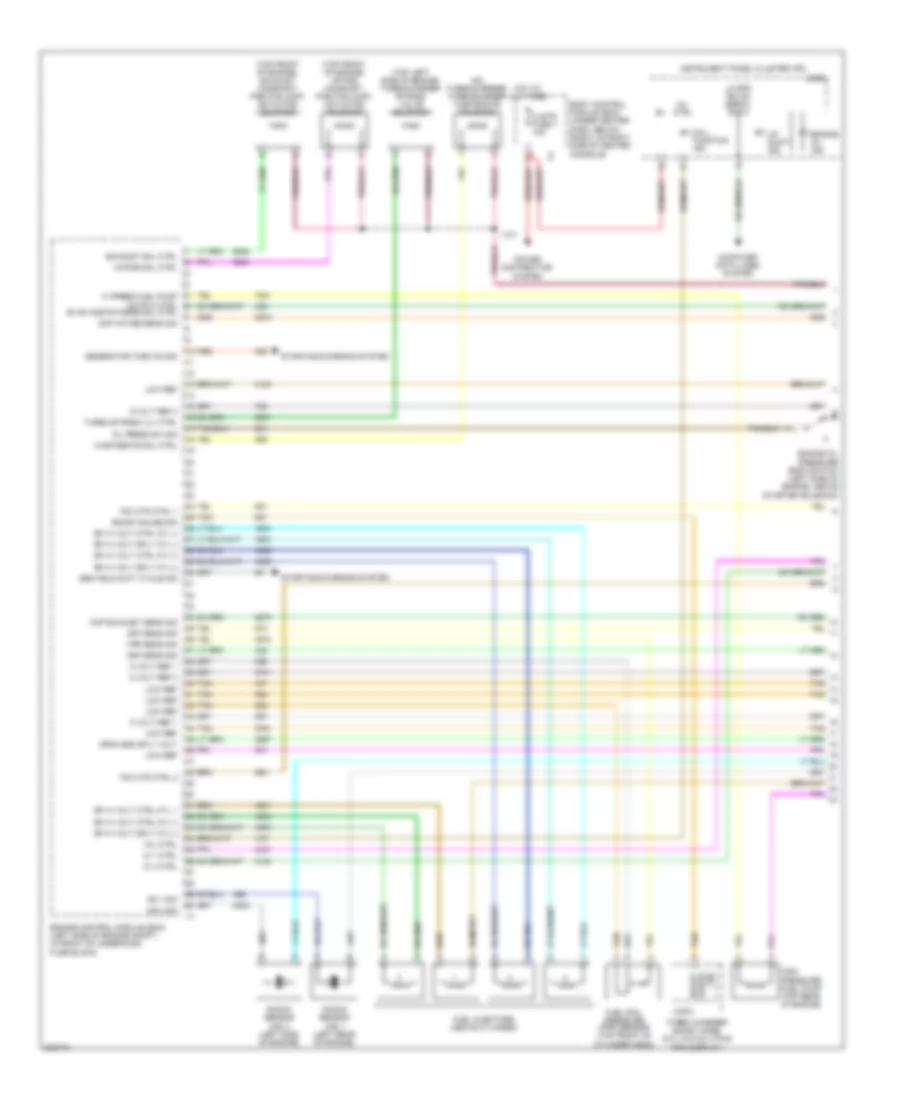
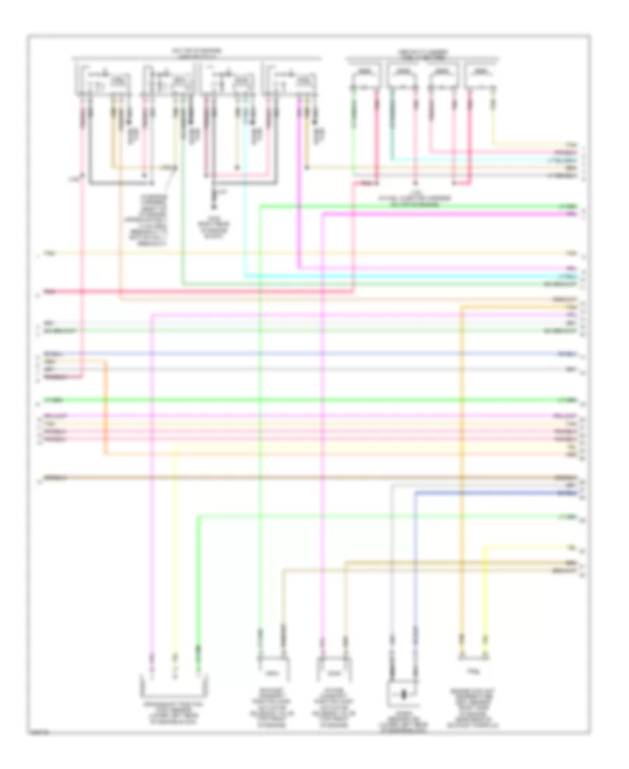
ENGINE PERFORMANCE
2.0L TURBO VIN X
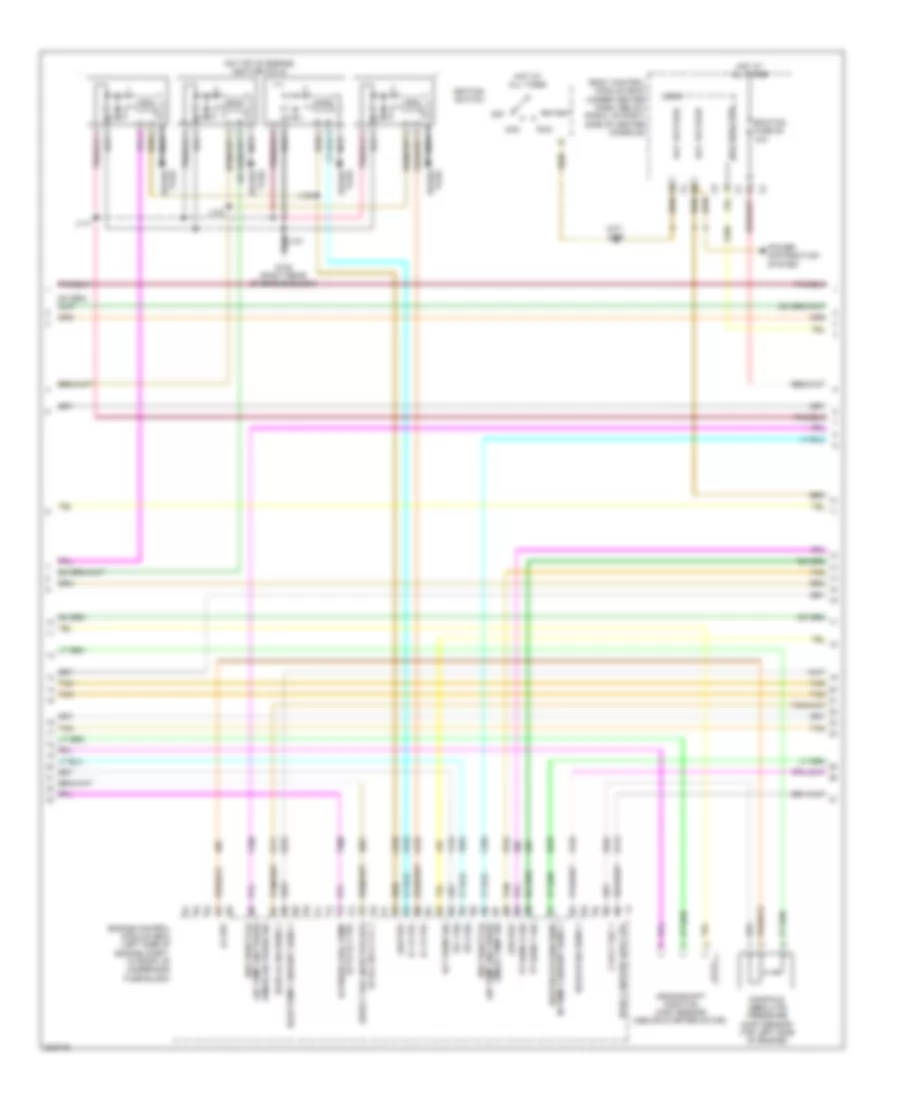
2.0L Turbo VIN X, Engine Performance Wiring Diagram (1 of 4) for Chevrolet HHR SS 2009
List of elements for 2.0L Turbo VIN X, Engine Performance Wiring Diagram (1 of 4) for Chevrolet HHR SS 2009:
- (on turbocharger) turbocharger wastegate solenoid
- (top front of engine) exhaust camshaft position (cmp) actuator solenoid
- (top front of engine) intake camshaft position (cmp) actuator solenoid
- (top left side of engine) turbocharger bypass valve solenoid
- 5 volt ref 1
- 5 volt ref 3
- 5-volt ref 2
- Body control module (bcm) (under center dash, below radio, on right side of center console)
- Boost gauge sig
- Ckp sens sig
- Clstr fuse 7 10a
- Cmp exhaust sens sig
- Cmp intake sens sig
- Computer data lines system
- Crnk sns sply volt
- Dfi hi volt ctrl cyl 1
- Dfi hi volt ctrl cyl 2
- Dfi hi volt ctrl cyl 3
- Dfi hi volt ctrl cyl 4
- Dfi hi volt sply cyl 2
- Dfi hi volt sply cyl 3
- Dfi hi volt sply cyl 4
- Engine control module (ecm) (left side of engine compt, in front of underhood fuse block)
- Engine oil ind
- Engine oil pressure (eop) switch (left side of engine, above starter solenoid)
- Evap cnstr purge sol ctrl
- Exhaust sol ctrl
- Frp sens sig
- Fuel injectors (above cylinder)
- Fuel rail pressure (fpr) sensor (top front of cylinder head)
- Gen field duty cycle sig
- Generator turn on sig
- Hi press fuel pump actr hi ctrl
- High pressure fuel pump (top rear of engine)
- Hot at all times
- Ic 1 ctrl
- Ic 4 ctrl
- Instrument panel cluster (ipc)
- Intake sol ctrl
- J121
- Knock sensor (ks) 1 (left rear of engine)
- Knock sensor (ks) 2 (left side of engine)
- Ks 1 sig
- Ks 2 sig
- Lo spd gmlan serial data
- Logic
- Low ref
- Mal- function ind
- Map sens sig
- Mil ctrl
- Oil press sw sig
- Power distribution system
- Sig gauge boost
- Starting/charging system
- Tac mtr ctrl 1
- Tac mtr ctrl 2
- Tan
- Turbo bypass vlv ctrl
- Turbo charger boost gage (2.0l w/o multiple info display)
- Up shift ind
- Wastegate sol ctrl
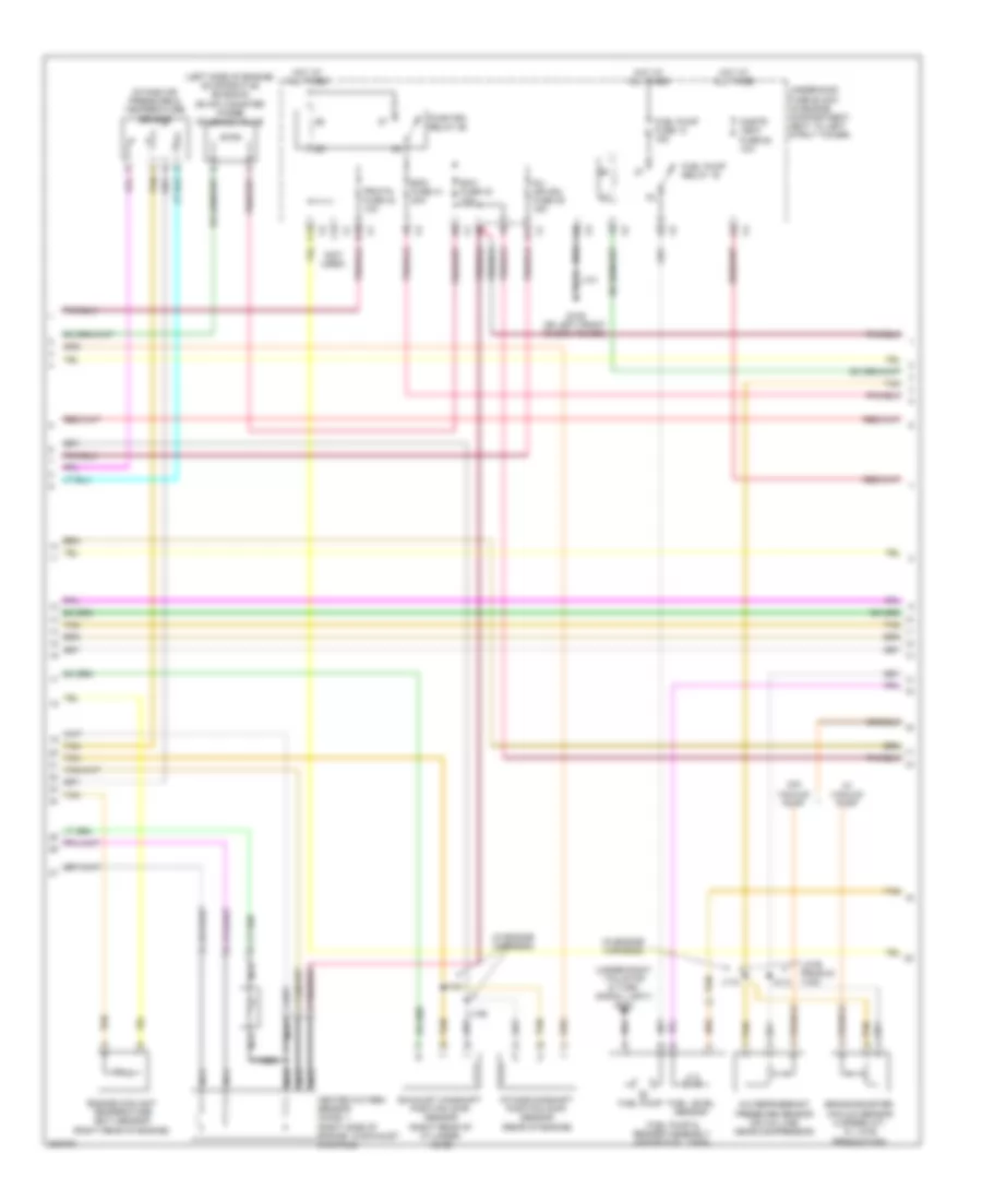
2.0L Turbo VIN X, Engine Performance Wiring Diagram (2 of 4) for Chevrolet HHR SS 2009
List of elements for 2.0L Turbo VIN X, Engine Performance Wiring Diagram (2 of 4) for Chevrolet HHR SS 2009:
- (a/t) j206
- (on top of engine) ignition coils
- (tmap) air press sig air temp and press
- (tmap) temp sig air temp and press
- 5 volt ref 1
- Acc
- Acc voltage
- Actr lo ctrl
- Body control module (bcm) (under center dash, below radio, on right side of center console)
- Crankshaft position (ckp) sensor (above starter motor)
- Direct fuel injector (dfi)
- Ecm/tcm fuse 25 10a
- Ect sens sig
- Engine control module (ecm) (left side of engine compt, in front of underhood fuse block)
- G108 (right rear of engine block)
- Heated oxygen sens
- Hi press fuel pump
- Hi vol sply cyl 1
- Ho2s 1 heater low ctrl
- Ho2s hi sig sens 1
- Ho2s lo sig sens 1
- Ho2s pump current sens 1
- Hot at all times
- Ic 2 ctrl
- Ic 3 ctrl
- Ignition switch
- In pump current sens 1
- J117
- J123
- J124
- Ks 1 sig
- Ks 2 sig
- Lo ref
- Logic
- Low ref
- Manifold absolute pressure (map) sensor (top left side of engine)
- Nca
- Off
- Power distribution system
- Pre-throttle
- Rly coil ctrl
- Run
- Spark plug
- Start
- Tan
- Tp sens 1 sig
- Tp sens 2 sig
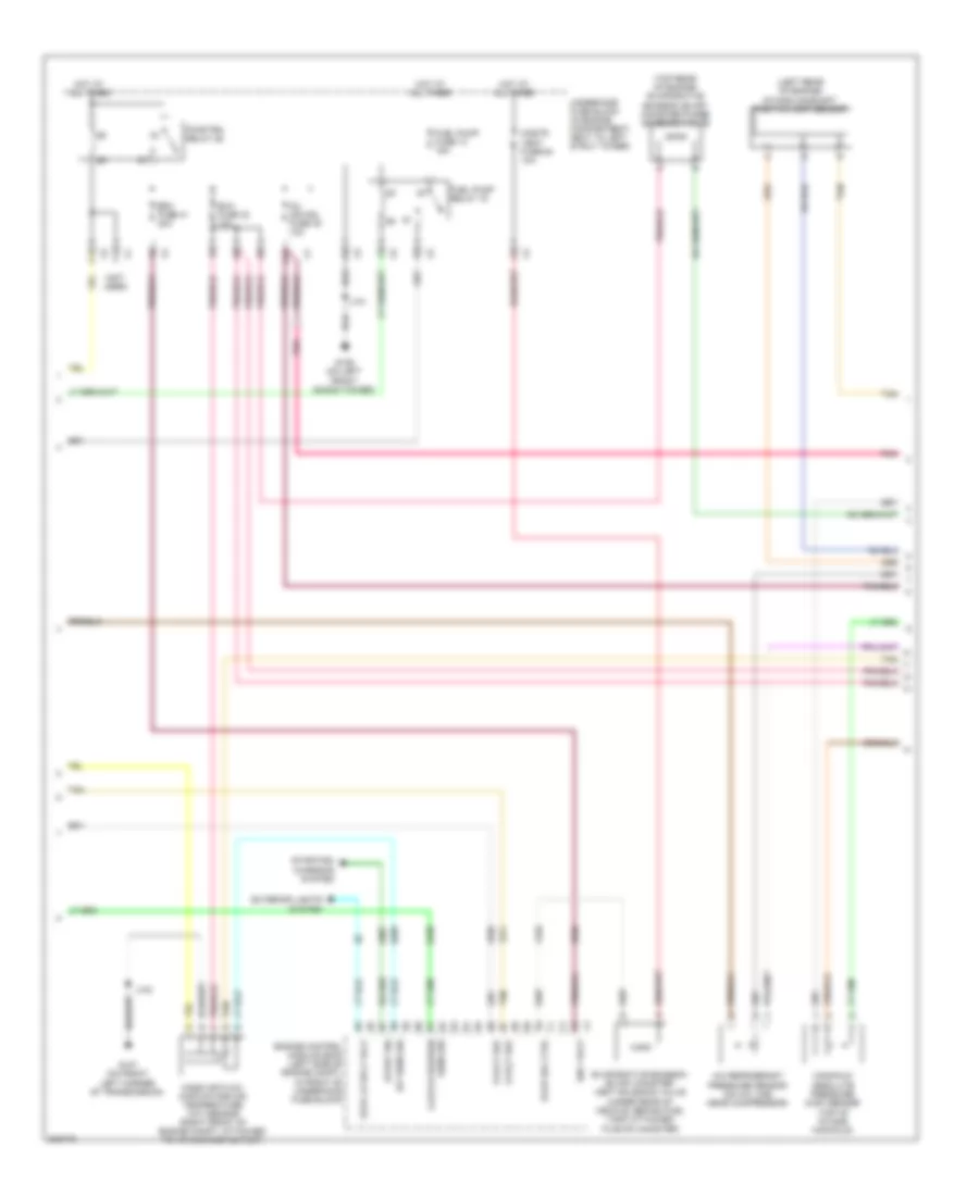
2.0L Turbo VIN X, Engine Performance Wiring Diagram (3 of 4) for Chevrolet HHR SS 2009
List of elements for 2.0L Turbo VIN X, Engine Performance Wiring Diagram (3 of 4) for Chevrolet HHR SS 2009:
- (in engine harness)
- (left side of engine) evaporative emission (evap) canister purge solenoid valve
- (not used)
- (under right tail/stop & turn signal light) g402
- A/c refrigerant pressure sensor (on a/c line, near compressor)
- A11
- B10
- Brake booster vacuum sensor (4 speed a/t, w/ late production)
- C12
- Cnstr vent fuse 64 10a
- Ecm fuse 41 20a
- Engine coolant temperature (ect) sensor (right rear of engine)
- Exh fuse 33 10a
- Exhaust camshaft position (cmp) sensor (right rear of cylinder head)
- F12
- Fuel level sensor
- Fuel pump
- Fuel pump & sender assembly (inside fuel tank)
- Fuel pump fuse 13 15a
- Fuel pump relay 19
- G109 (on left front shock tower)
- Heated oxygen sensor (ho2s) 1 (right side of engine, in exhaust manifold)
- Hot at all times
- Inj ign mdl fuse 45 15a
- Intake air pressure & temperature sensor
- Intake camshaft position (cmp) sensor (rear of engine)
- J114
- J115
- J126
- J140
- Late produc- tion
- Nca
- Prwtn fuse 42 10a
- Pwr/trn relay 26
- Tan
- Underhood fuse block (in engine compartment, next to left strut tower)
- W/ vacuum pump
- W/o vacuum pump
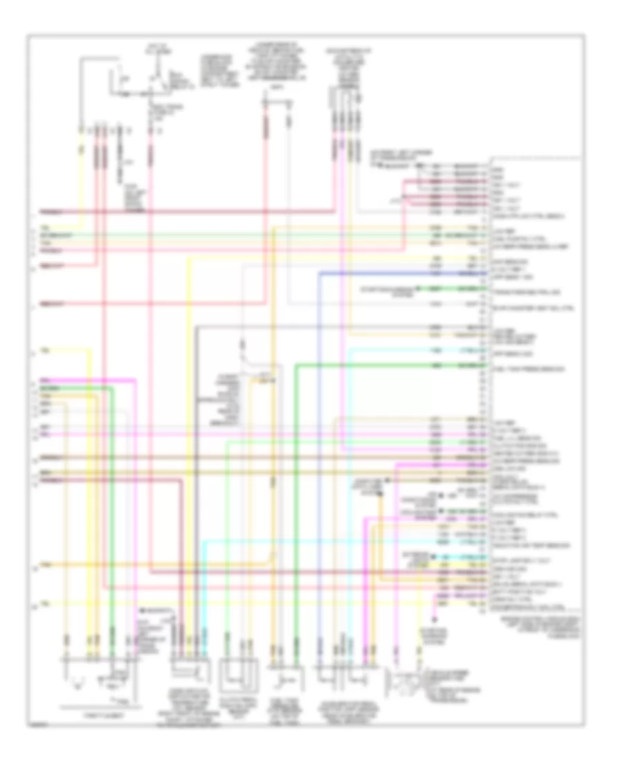
2.0L Turbo VIN X, Engine Performance Wiring Diagram (4 of 4) for Chevrolet HHR SS 2009
List of elements for 2.0L Turbo VIN X, Engine Performance Wiring Diagram (4 of 4) for Chevrolet HHR SS 2009:
- (downstream of catalytic converter) heated oxygen sensor (ho2s) 2
- (in body harness main bundle, approximately 15 cm rear of first breakout)
- (m/t) j211
- (on front left corner of transmission) g107
- (under rear of vehicle, behind fuel tank attached to evap canister) evaporative emission (evap) canister vent solenoid valve
- 5 volt ref 1
- 5 volt ref 2
- 5 volt ref 3
- A/c compressor clutch rly ctrl
- A/c refr press sens lo ref
- A/c refr press sens sig
- A10
- A11
- Acc volt hi spd gmlan serial data bus (+)
- Accelerator pedal position (app) sensor (near accelerator pedal bracket)
- Air conditioning system
- App sens 1 sig
- App sens 2 sig
- Batt positive volt
- Clutch pedal position (cpp) sensor (m/t)
- Clutch pos sns sig
- Computer data lines system
- Cooling fan relay ctrl
- Cooling fans system
- Crnk rly ctrl
- Ecm trans fuse 43 15a
- Engine control module (ecm) (left side of engine compt, in front of underhood fuse block)
- Evap canister vent sol ctrl
- Exterior lights system
- Fuel lvl sens sig
- Fuel pump rly ctrl
- Fuel tank press sens sig
- Fuel tank pressure (ftp) sensor (on top of fuel tank)
- G109 (on left front shock tower)
- Gmlan serial data bus (-)
- Gnd
- Heated oxygen sns hi 2
- Ho2s htr low ctrl sens 2
- Hot at all times
- Ign 1 volt
- Induction air temp sens sig
- J101
- J103
- J112
- J113
- Low ref
- Low ref heated oxygen low sig sens 2
- Maf sens sig
- Mass air flow (maf)/intake air temperature (iat) sensor (right front of engine compt, attached to air cleaner outlet)
- Nca
- Oss high sig
- Oss low sig
- Powertrain rly coil ctrl
- Run crank relay 51
- Starting/ charging system
- Starting/charging system
- Stop lamp sply volt
- Tan
- Tan a
- Throttle body
- Tps1
- Tps2
- Trans park/neutral sig
- Underhood fuse block (in engine compartment, next to left strut tower)
- Vehicle speed sensor (vss) (m/t) (at rear of engine, on top of transmission)
2.2L VIN B
2.2L VIN B, Engine Performance Wiring Diagram (1 of 4) for Chevrolet HHR SS 2009
List of elements for 2.2L VIN B, Engine Performance Wiring Diagram (1 of 4) for Chevrolet HHR SS 2009:
- (under right tail/stop & turn signal light) g402
- 5-volt ref
- A10
- A11
- Acc
- Acc volt
- Acc voltage
- Accelerator pedal position (app) sensor (on accelerator pedal bracket)
- Air conditioning system
- App sens 1 sig
- App sens 2 sig
- App sensor 1
- App sensor 2
- Batt positive volt
- Body control module (bcm) (under center dash, below radio, on right side of center console)
- Clutch pedal position (cpp) sensor (m/t)
- Clutch pos sens rtn
- Clutch rly ctrl
- Computer data lines system
- Cooling fan rly ctrl
- Cooling fans system
- Ecm tcm fuse 25 10a
- Ecm trans fuse 43 15a
- Enable rly ctrl
- Engine control module (ecm) (left side of engine compt, in front of underhood fuse block)
- Engine oil ind
- Fuel level sensor
- Fuel lvl sens sig
- Fuel pump
- Fuel pump & sender assembly (inside fuel tank)
- Fuel pump rly ctrl
- Fuel tank pressure (ftp) sensor (on top of fuel tank)
- G109 (on left front shock tower)
- Ground
- Hot at all times
- Ign 1 volt
- Ignition switch
- Instrument panel cluster (ipc)
- J101
- J206 (a/t)
- Lo spd gmlan serial data
- Logic
- Low ref
- Maf sens sig
- Mal- function ind
- Mil ctrl
- Off
- Power distribution system
- Powertrain rly ctrl
- Press sens sig
- Rly coil ctrl
- Run
- Run/ crank relay 51
- Serial data (+)
- Serial data (-) clutch position sens sply
- Start
- Starting/charging system
- Tan
- Transmissions system
- Underhood fuse block (in engine compartment, next to left strut tower)
- Up shift ind
- Vehicle speed sensor (vss) (m/t) (at rear of engine, on top of transmission)
- Vss signal high
- Vss signal low
2.2L VIN B, Engine Performance Wiring Diagram (2 of 4) for Chevrolet HHR SS 2009
List of elements for 2.2L VIN B, Engine Performance Wiring Diagram (2 of 4) for Chevrolet HHR SS 2009:
- (left rear of engine) intake camshaft position (cmp) sensor
- (not used)
- (top rear of engine) evaporative emission (evap) canister purge solenoid valve
- 5-volt ref
- A/c refrigerant pressure sensor (on a/c line, near compressor)
- A11
- C12
- Cnstr vent fuse 64 10a
- Ecm fuse 41 20a
- Engine control module (ecm) (left side of engine compt, in front of underhood fuse block)
- Evap sol ctrl
- Evaporative emission (evap) canister vent solenoid valve (under rear of vehicle, behind fuel tank attached to evap canister)
- Exh fuse 33 10a
- Exterior lights system
- F12
- Fuel pump fuse 13 15a
- Fuel pump relay 19
- G107 (on front left corner of transmission)
- G109 (on left front shock tower)
- Hot at all times
- Iat sens sig
- Ign 1 volt
- Inj ign mdl fuse 45 10a
- J101
- J103
- Manifold absolute pressure (map) sensor (top of intake manifold)
- Mass air flow (maf)/intake air temperature (iat) sensor (right front of engine compt, attached to air cleaner outlet)
- Pnk
- Pwr/trn relay 26
- Sens sig clutch position
- Start sig
- Starting/ charging system
- Stop lp sply volt
- Tan
- Underhood fuse block (in engine compartment, next to left strut tower)
2.2L VIN B, Engine Performance Wiring Diagram (3 of 4) for Chevrolet HHR SS 2009
List of elements for 2.2L VIN B, Engine Performance Wiring Diagram (3 of 4) for Chevrolet HHR SS 2009:
- (above cylinders) fuel injectors
- (in engine harness, near top of engine, approximately 13 cm from breakout to ignition coil 1 breakout)
- (on top of engine) ignition coils
- Crankshaft position (ckp) sensor (lower left rear of engine block)
- Engine coolant temperature (ect) sensor (right side of engine, near rear of exhaust manifold)
- Exhaust camshaft position (cmp) actuator solenoid valve (top front of engine)
- G108 (right rear of engine block)
- Intake camshaft position (cmp) actuator solenoid valve (top front of engine)
- J104 (in fuel injector harness on top of engine)
- J105
- J106
- Knock sensor (ks) (lower left rear of engine block)
- Nca
- Plug spark
- Pnk
- Spark plug
- Tan
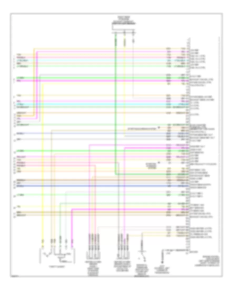
2.2L VIN B, Engine Performance Wiring Diagram (4 of 4) for Chevrolet HHR SS 2009
List of elements for 2.2L VIN B, Engine Performance Wiring Diagram (4 of 4) for Chevrolet HHR SS 2009:
- (right rear of engine) exhaust camshaft position (cmp) sensor
- 5 volt ref
- 5-volt ref
- 5-volt ref 2
- Ckp sens 1 sig
- Cmp exhaust sens
- Cmp intake sens
- Ect sens sig
- Engine control module (ecm) (left side of engine compt, in front of
- Engine oil pressure (eop) switch (lower left rear of engine block)
- Evap canister purge sol ctrl
- Exhaust cam sol ctrl
- Exhaust cam sol rtn
- Exhaust sens low ref
- Exhaust sens ref volt
- Fuel inj 1 ctrl
- Fuel inj 2 ctrl
- Fuel inj 3 ctrl
- Fuel inj 4 ctrl
- G107 (on front left corner of transmission)
- Gen field duty cycle sig
- Generator turn on sig
- Heated oxygen sensor (ho2s) 1 (right side of engine, in exhaust manifold)
- Heated oxygen sensor (ho2s) 2 (downstream of catalytic converter)
- Ho2s heater lo ctrl
- Ho2s hi sig
- Ho2s lo ref
- Ho2s ref volt
- Ic 1 ctrl
- Ic 2 ctrl
- Ic 3 ctrl
- Ic 4 ctrl
- Intake cam sol ctrl
- Intake cam sol rtn
- Intake sens low ref
- Intake sens ref volt
- J103
- Knock sens sig
- Knock sens sig rtn
- Low ref
- Map sens sig
- Nca
- Oil press sw sig
- Sig gnd
- Starting/ charging system
- Starting/charging system
- Tac mtr ctrl 1
- Tac mtr ctrl 2
- Tan
- Throttle body
- Tp sens 1 sig
- Tp sens 2 sig
- Tps1
- Tps2
- Underhood fuse block)
2.4L VIN V
2.4L VIN V, Engine Performance Wiring Diagram (1 of 4) for Chevrolet HHR SS 2009
List of elements for 2.4L VIN V, Engine Performance Wiring Diagram (1 of 4) for Chevrolet HHR SS 2009:
- (under right tail/stop & turn signal light) g402
- 5-volt ref
- A10
- A11
- Acc
- Acc volt
- Acc voltage
- Accelerator pedal position (app) sensor (on accelerator pedal bracket)
- Air conditioning system
- App sens 1 sig
- App sens 2 sig
- App sensor 1
- App sensor 2
- Batt positive volt
- Body control module (bcm) (under center dash, below radio, on right side of center console)
- Clutch pedal position (cpp) sensor (m/t)
- Clutch pos sens rtn
- Clutch rly ctrl
- Computer data lines system
- Cooling fan rly ctrl
- Cooling fans system
- Ecm tcm fuse 25 10a
- Ecm trans fuse 43 15a
- Enable rly ctrl
- Engine control module (ecm) (left side of engine compt, in front of underhood fuse block)
- Engine oil ind
- Fuel level sensor
- Fuel lvl sens sig
- Fuel pump
- Fuel pump & sender assembly (inside fuel tank)
- Fuel pump rly ctrl
- Fuel tank pressure (ftp) sensor (on top of fuel tank)
- G109 (on left front shock tower)
- Ground
- Hot at all times
- Ign 1 volt
- Ignition switch
- Instrument panel cluster (ipc)
- J101
- J206 (a/t)
- Lo spd gmlan serial data
- Logic
- Low ref
- Maf sens sig
- Mal- function ind
- Mil ctrl
- Off
- Power distribution system
- Powertrain rly ctrl
- Press sens sig
- Rly coil ctrl
- Run
- Run/ crank relay 51
- Serial data (+)
- Serial data (-) clutch position sens sply
- Start
- Starting/charging system
- Tan
- Transmissions system
- Underhood fuse block (in engine compartment, next to left strut tower)
- Up shift ind
- Vehicle speed sensor (vss) (m/t) (at rear of engine, on top of transmission)
- Vss signal high
- Vss signal low
2.4L VIN V, Engine Performance Wiring Diagram (2 of 4) for Chevrolet HHR SS 2009
List of elements for 2.4L VIN V, Engine Performance Wiring Diagram (2 of 4) for Chevrolet HHR SS 2009:
- (left rear of engine) intake camshaft position (cmp) sensor
- (not used)
- (top rear of engine) evaporative emission (evap) canister purge solenoid valve
- 5-volt ref
- A/c refrigerant pressure sensor (on a/c line, near compressor)
- A11
- C12
- Cnstr vent fuse 64 10a
- Ecm fuse 41 20a
- Engine control module (ecm) (left side of engine compt, in front of underhood fuse block)
- Evap sol ctrl
- Evaporative emission (evap) canister vent solenoid valve (under rear of vehicle, behind fuel tank attached to evap canister)
- Exh fuse 33 10a
- Exterior lights system
- F12
- Fuel pump fuse 13 15a
- Fuel pump relay 19
- G107 (on front left corner of transmission)
- G109 (on left front shock tower)
- Hot at all times
- Iat sens sig
- Ign 1 volt
- Inj ign mdl fuse 45 10a
- J101
- J103
- Manifold absolute pressure (map) sensor (top of intake manifold)
- Mass air flow (maf)/intake air temperature (iat) sensor (right front of engine compt, attached to air cleaner outlet)
- Pnk
- Pwr/trn relay 26
- Sens sig clutch position
- Start sig
- Starting/ charging system
- Stop lp sply volt
- Tan
- Underhood fuse block (in engine compartment, next to left strut tower)
2.4L VIN V, Engine Performance Wiring Diagram (3 of 4) for Chevrolet HHR SS 2009
List of elements for 2.4L VIN V, Engine Performance Wiring Diagram (3 of 4) for Chevrolet HHR SS 2009:
- (above cylinders) fuel injectors
- (in engine harness, near top of engine, approximately 13 cm from breakout to ignition coil 1 breakout)
- (on top of engine) ignition coils
- Crankshaft position (ckp) sensor (lower left rear of engine block)
- Engine coolant temperature (ect) sensor (right side of engine, near rear of exhaust manifold)
- Exhaust camshaft position (cmp) actuator solenoid valve (top front of engine)
- G108 (right rear of engine block)
- Intake camshaft position (cmp) actuator solenoid valve (top front of engine)
- J104 (in fuel injector harness on top of engine)
- J105
- J106
- Knock sensor (ks) (lower left rear of engine block)
- Nca
- Plug spark
- Pnk
- Spark plug
- Tan
2.4L VIN V, Engine Performance Wiring Diagram (4 of 4) for Chevrolet HHR SS 2009
List of elements for 2.4L VIN V, Engine Performance Wiring Diagram (4 of 4) for Chevrolet HHR SS 2009:
- (right rear of engine) exhaust camshaft position (cmp) sensor
- 5 volt ref
- 5-volt ref
- 5-volt ref 2
- Ckp sens 1 sig
- Cmp exhaust sens
- Cmp intake sens
- Ect sens sig
- Engine control module (ecm) (left side of engine compt, in front of
- Engine oil pressure (eop) switch (lower left rear of engine block)
- Evap canister purge sol ctrl
- Exhaust cam sol ctrl
- Exhaust cam sol rtn
- Exhaust sens low ref
- Exhaust sens ref volt
- Fuel inj 1 ctrl
- Fuel inj 2 ctrl
- Fuel inj 3 ctrl
- Fuel inj 4 ctrl
- G107 (on front left corner of transmission)
- Gen field duty cycle sig
- Generator turn on sig
- Heated oxygen sensor (ho2s) 1 (right side of engine, in exhaust manifold)
- Heated oxygen sensor (ho2s) 2 (downstream of catalytic converter)
- Ho2s heater lo ctrl
- Ho2s hi sig
- Ho2s lo ref
- Ho2s ref volt
- Ic 1 ctrl
- Ic 2 ctrl
- Ic 3 ctrl
- Ic 4 ctrl
- Intake cam sol ctrl
- Intake cam sol rtn
- Intake sens low ref
- Intake sens ref volt
- J103
- Knock sens sig
- Knock sens sig rtn
- Low ref
- Map sens sig
- Nca
- Oil press sw sig
- Sig gnd
- Starting/ charging system
- Starting/charging system
- Tac mtr ctrl 1
- Tac mtr ctrl 2
- Tan
- Throttle body
- Tp sens 1 sig
- Tp sens 2 sig
- Tps1
- Tps2
- Underhood fuse block)
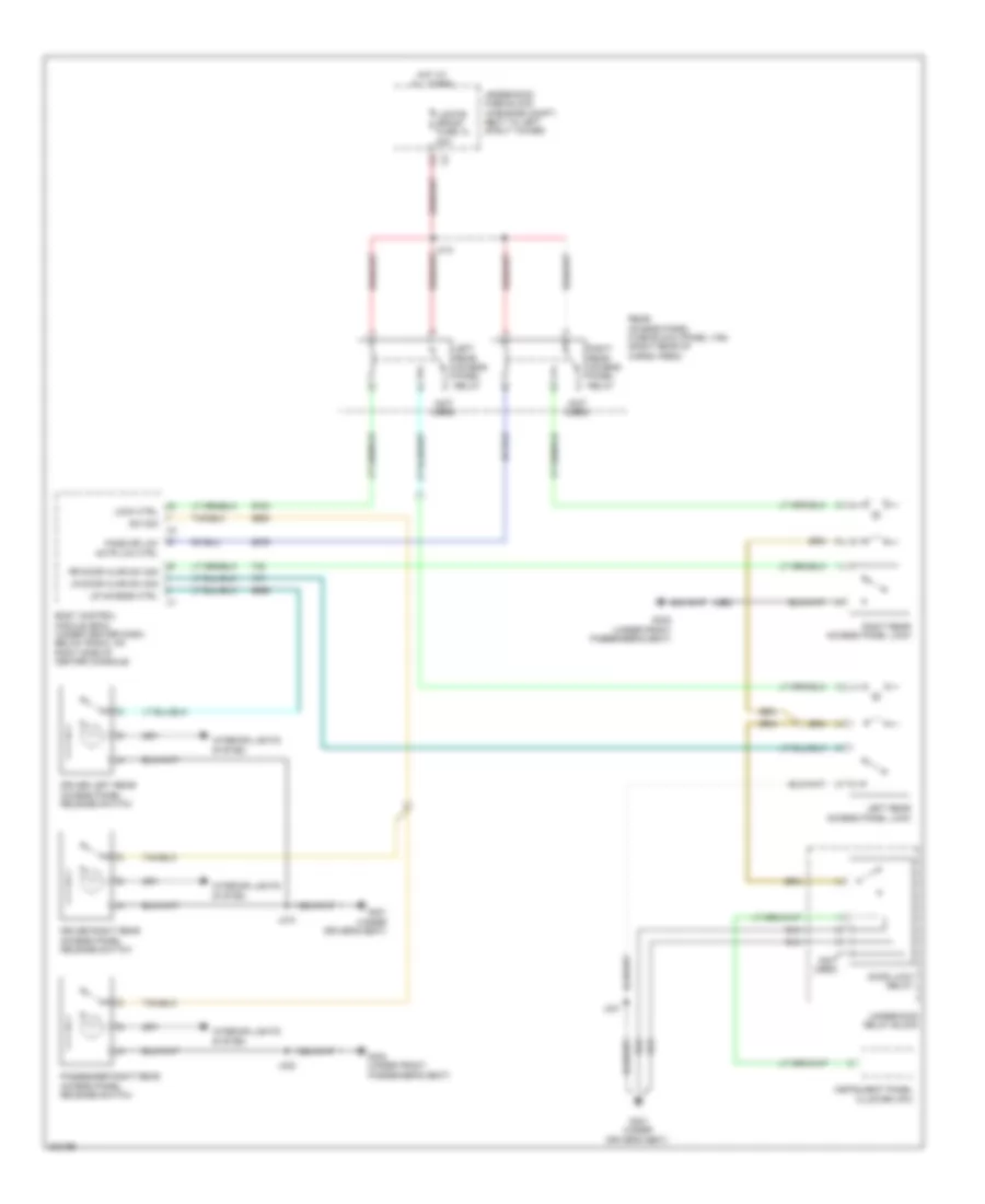
EXTERIOR LIGHTS
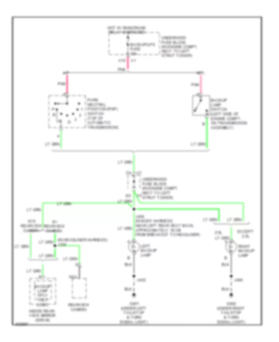
Backup Lamps Wiring Diagram for Chevrolet HHR SS 2009
List of elements for Backup Lamps Wiring Diagram for Chevrolet HHR SS 2009:
- (in headliner harness) j326
- 2.0l
- A/t
- A10
- Backup lamp sply volt
- Backup lamp switch (left side of engine compt, on transmission assembly)
- Backup/lps fuse 10a
- Except 2.0l
- G401 (under left tail/stop & turn signal light)
- G402 (under right tail/stop & turn signal light)
- Hot w/ run/crank relay energized
- Inside rear- view mirror (isrvm)
- J400
- J402
- Left backup lamp
- Logic
- M/t
- Nca
- Park neutral position (pnp) switch (top of automatic transmission)
- Pnk
- Rearview camera
- Right backup lamp
- Underhood fuse block (in engine compt, next to left strut tower)
- W/ rearview camera
- W/o rearview camera
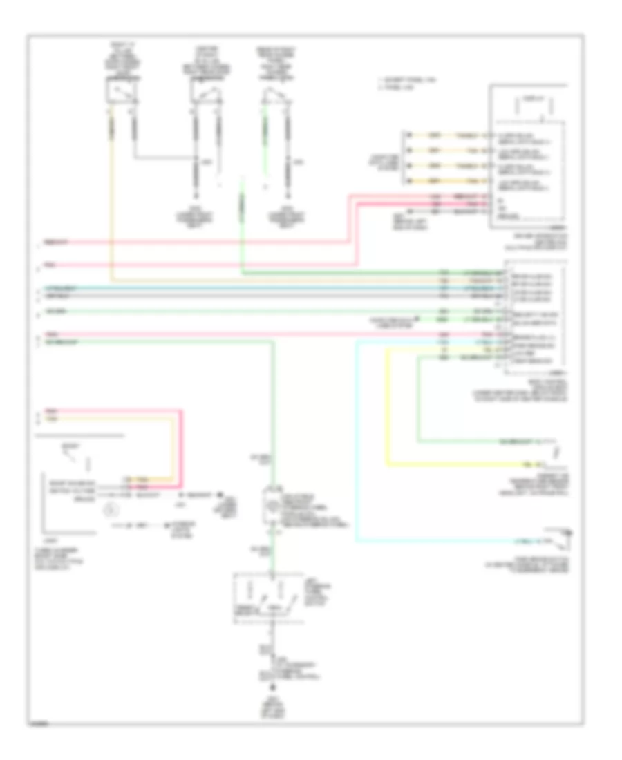
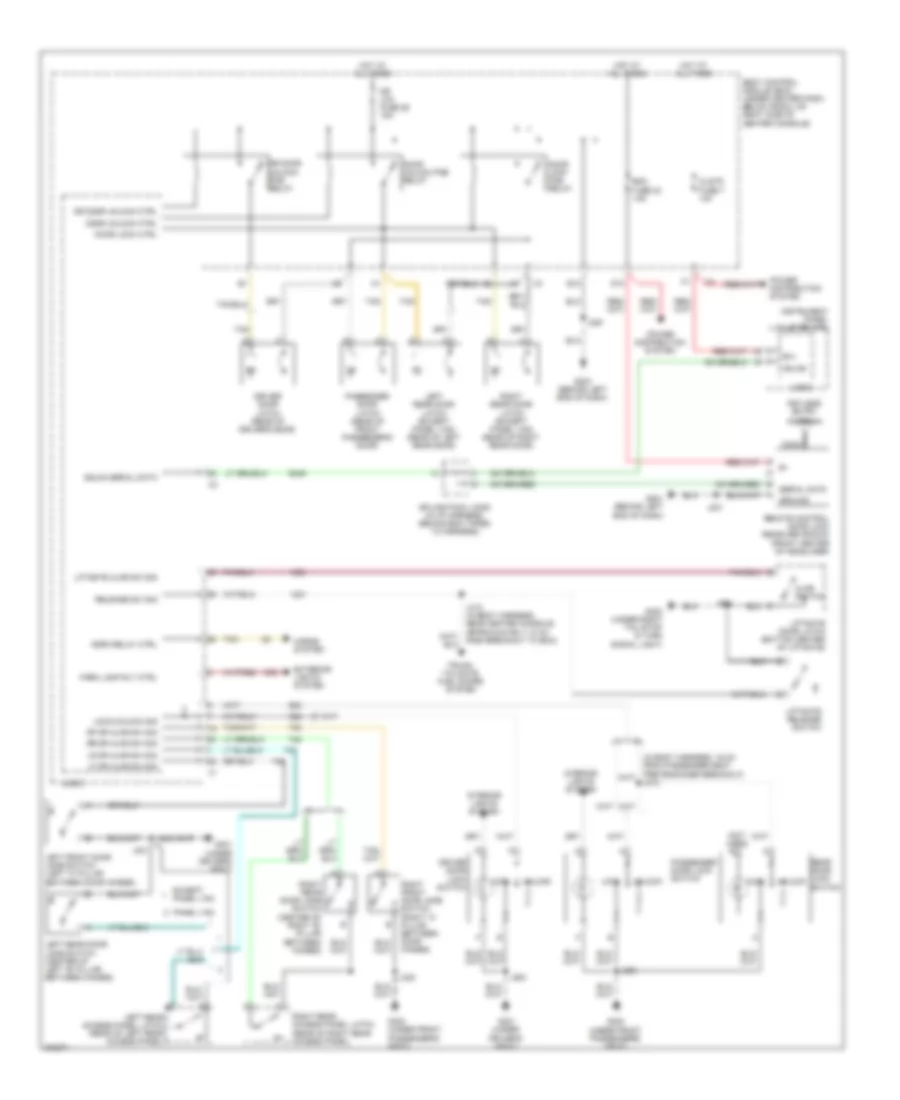
Exterior Lamps Wiring Diagram (1 of 2) for Chevrolet HHR SS 2009
List of elements for Exterior Lamps Wiring Diagram (1 of 2) for Chevrolet HHR SS 2009:
- (behind left end of dash) g201
- (not used)
- 5v ref
- A12
- Auto
- B6 x4
- Body control module (bcm) (under center dash, below radio, on right side of center console)
- Brake pedal position (bpp) sensor (on brake pedal mounting bracket)
- Center high mounted stop lamp (chmsl)
- Chmsl relay
- Chmsl rly coil ctrl
- Computer data lines system
- E12
- G109 (on left front shock tower)
- G111 (left side of engine compt)
- G203 (behind left end of dash)
- G301 (under driver's seat)
- G402 (under right tail/stop & turn signal light)
- Ground
- Hazard sw sign
- Hazard switch
- Head
- Headlamp switch
- High speed gmlan serial data bus +
- High speed gmlan serial data bus -
- Hot at all times
- Instrument panel cluster (ipc)
- Interior lights system
- J101
- J102
- J200
- J201
- J900
- Jx205 (in i/p harness, behind bcm taped to harness)
- Left
- Left front side marker lamp
- Left park/ turn signal lamp
- Left rear stop/turn
- Left turn ind
- Left turn sig lamp
- Logic
- Low ref
- Low speed gmlan serial data
- Lr turn sig sw sig
- Off
- Park
- Park lamp relay ctrl
- Park lamp sw sign
- Prk lamps fuse 10a
- Prk lamps relay
- Right
- Right front side marker lamp
- Right park/ turn signal lamp
- Right rear stop/turn
- Right turn ind
- Right turn sig lamp
- Rr turn sig sw sig
- Sens sig
- Serial data
- Stop lp fuse 10a
- Tan
- Turn signal/ multi- function switch
- Turn switch
- Underhood fuse block (in engine compt, next to left strut tower)
- Underhood relay block
- X1 a9
- X4 b5
Exterior Lamps Wiring Diagram (2 of 2) for Chevrolet HHR SS 2009
List of elements for Exterior Lamps Wiring Diagram (2 of 2) for Chevrolet HHR SS 2009:
- (2.0l turbo)
- (except 2.0l turbo)
- (in body harness, near right rear, approximately 33 cm from breakout to tail/stop lamp - right) j403
- Engine control module (ecm) (left side of engine compt, in front of underhood fuse block)
- G401 (under left tail/stop & turn signal light)
- G402 (under right tail/stop & turn signal light)
- Interior lights system
- J400
- J402
- J900
- Left license lamp
- Left rear marker lamp
- Left tail/ stop & turn signal lamp
- Right license lamp
- Right rear marker lamp
- Right tail/ stop & turn signal lamp
- Stop lamp sw sig
- Transmission control module (tcm) (a/t) (left side of engine compt)
GROUND DISTRIBUTION
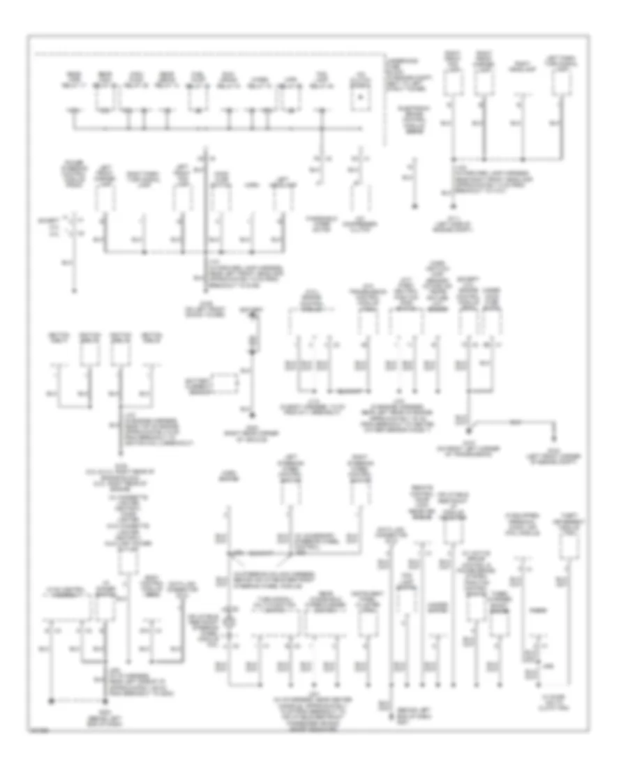
Ground Distribution Wiring Diagram (1 of 3) for Chevrolet HHR SS 2009
List of elements for Ground Distribution Wiring Diagram (1 of 3) for Chevrolet HHR SS 2009:
- (2.0l) engine control module
- (a/t) park/ neutral position (pnp) switch
- (a/t) transmission control module (tcm)
- (behind left end of dash) g201
- (except 2.0l) engine control module (ecm)
- (if equipped) personal audio link (pal) module
- (in steering column harness, behind inflatable restraint steering wheel module)
- (w/ active brake control & power brake system) traction control switch
- (w/ cigarette lighter ashtray) cigar lighter
- (w/o cigarette lighter ashtray) auxiliary power outlet
- 2.0l
- 87a
- A/c clutch diode 9
- A/c compressor clutch
- B x2
- B x3
- Battery
- Battery current sensor
- Body control module (bcm)
- Data link connector (dlc)
- E12 x4
- E6 x1
- Electronic brake control module (ebcm)
- Except 2.0l
- Fog lamp relay 54
- Fog lamp switch
- Fuel pump relay 19
- G103 (left front corner of engine compt)
- G107 (on front left corner of transmission)
- G108 (2.2l & 2.4l: right rear of engine block) (2.ol: right rear of engine)
- G109 (on left front shock tower)
- G111 (left side of engine compt)
- G203 (behind left end of dash)
- G403 (right rear corner of vehicle)
- Hazard switch
- Hood ajar switch
- Horn
- Horn switch
- Hvac control assembly
- I/p dimmer switch
- Ignition coil 1
- Ignition coil 2
- Ignition coil 3
- Ignition coil 4
- Inflatable restraint i/p module indicator
- Inflatable restraint steering wheel module coil
- Instrument panel cluster (ipc)
- J101 (in forward lamp harness, near left front headlamp, approximately 9 cm from breakout to g109)
- J103 (in engine harness, near left rear of engine, approximately 30 cm from breakout to heated oxygen sensor (ho2s) 1)
- J107 (in engine harness, near top of engine, approximately 6 cm from breakout to ignition coil 2 breakout)
- J112 (in body harness, 7.5 cm from g111 breakout)
- J195
- J200 (in i/p harness, near left side of i/p, approximately 29 cm from breakout to g203)
- J201 (in i/p harness, near center console, approximately 18 cm from breakout to inflatable restraint passenger air bag on/off indicator)
- J202
- Left front fog lamp
- Left front marker lamp
- Left headlamp
- Left park/ turn signal lamp
- Left steering wheel control switch
- Mass air flow (maf) sensor/ intake air tempe- rature (iat) sensor
- Power steering control module (pscm)
- Radio
- Rear defog relay 14
- Rear windshield wiper/washer switch
- Rear wpr relay 17
- Rear wsw relay 48
- Remote control door lock receiver (rcdlr)
- Right front fog lamp
- Right front marker lamp
- Right headlamp
- Right park/ turn signal lamp
- Right steering wheel control switch
- Run/ crank relay 51
- Steering wheel control) j208
- Theft deterrent module (tdm)
- Turbo charger boost gauge
- Turn signal/ multi-function switch
- Under- hood fuse block
- Underhood fuse block (in engine compt, next to left strut tower)
- W/ duke/ malta cloth trim
- Windshield wiper motor
- Wiper relay 70
- Wpr relay 52
- Wsw pump relay 39
- X1 d3
- X1 k
- X2 f9
- X2 k
- X3 c5
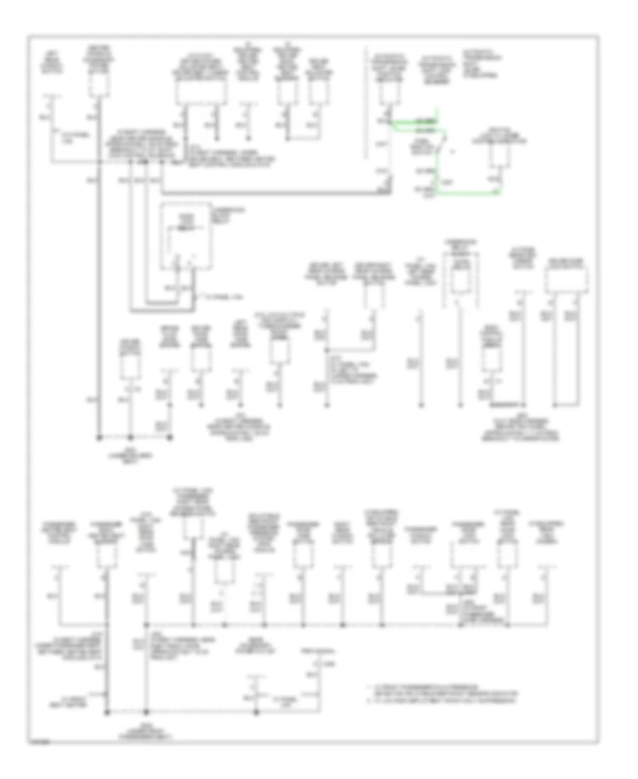
Ground Distribution Wiring Diagram (2 of 3) for Chevrolet HHR SS 2009
List of elements for Ground Distribution Wiring Diagram (2 of 3) for Chevrolet HHR SS 2009:
- (2.ol w/o multiple info display) turbocharger boost gage
- (if equipped) driver back heated seat element
- (if equipped) driver heated seat control module
- (if equipped) inflatable restraint vehicle rollover sensor
- (if equipped) rear view camera
- (in body harness, near center console, approximately 29 cm from breakout to a/t shift lock control solenoid) j300
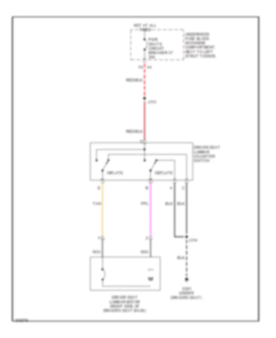
- (w/ 6 way driver power adjuster seat) driver seat lumbar adjuster switch
- (w/ panel van) left rear access panel lock
- (w/ panel van) passenger right rear access panel release switch
- (w/ panel van) rear door lock switch
- (w/ panel van) right rear access panel lock
- (w/o panel van) right rear door jamb switch
- A x2
- Automatic transmission shift lever (if equipped)
- Automatic transmission shift lever position indicator
- Automatic transmission shift lock control solenoid
- Body control module (bcm)
- Brake fluid level switch
- C x406
- Center console accessory power outlet
- Chmsl relay
- Detector inflatable restraint sensor indicator
- Door lock relay
- Driver door jamb switch
- Driver door lock switch
- Driver left rear access panel release switch
- Driver right rear access panel release switch
- Driver seat adjuster switch
- Driver window switch
- G301 (under driver's seat)
- G302 (under front passenger's seat)
- Ignition lock cylinder control actuator
- Inflatable restraint passenger presence system (pps) module
- J301 (in body harness, near center console, approximately 29 cm from j300)
- J314 (in seat harness, under driver seat, between heated seat control module & c315)
- J315 (in seat harness, under passenger seat, between heated seat module & x314)
- J500 (in lf door harness, behind trim panel, approximately 17 cm from breakout to mirror motor)
- Left rear door jamb switch
- Left rear window switch
- Nca
- Outside rearview mirror switch
- Park position switch
- Passenger back heated seat element
- Passenger door jamb switch
- Passenger door lock switch
- Passenger heated seat control module
- Passenger window switch
- Provisional
- Rear accessory power outlet
- Right front door, approximately 18 cm from j307)
- Right rear window switch
- Underhood block relay
- Underhood relay block
- W/ front passenger/child presence
- W/ front seat heater
- W/ low risk deployment infant-only suppression
- W/ panel van
- W/o panel van
- X307 c
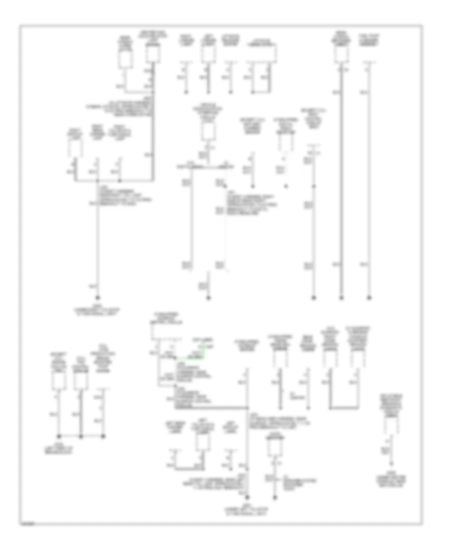
Ground Distribution Wiring Diagram (3 of 3) for Chevrolet HHR SS 2009
List of elements for Ground Distribution Wiring Diagram (3 of 3) for Chevrolet HHR SS 2009:
- (2.0l late production) brake booster pump motor
- (2.0l) fan control module
- (except 2.0l) battery current sensor
- (except 2.0l) body control module (bcm)
- (except 2.0l) engine cooling fan
- (if equipped) digital radio receiver
- (if equipped) inside rearview mirror
- (if equipped) sunroof control module
- (if equipped) sunroof switch
- (not used)
- (under center console, near sdm module)
- (w/ sunroof) overhead console courtesy, reading lamps
- (w/o sunroof) front dome/ reading lamps
- A x2
- Audio amplifier
- Center high mounted stop lamp (chmsl)
- Fuel pump & sender assembly
- G105 (left front of engine block)
- G306
- G401 (under left tail/stop & turn signal light)
- G402 (under right tail/stop & turn signal light)
- Inflatable restraint sensing & diagnostic module (sdm)
- J303 (in headliner harness, near sunroof, approximately 11 cm from breakout to x397)
- J400 (in body harness, near right tail lamp, approximately 27 cm from breakout to g402)
- J401 (in body harness, right side of rear compt, approximately 6 cm from breakout to digital radio receiver)
- J402 (in body harness, near left rear tail lamp, approximately 11 cm from g401 breakout)
- J900 (in liftgate harness, in rear liftgate, approximately 16 cm from breakout to rear wiper motor)
- Left backup lamp
- Left license lamp
- Left rear marker lamp
- Left tail/stop & turn signal lamp
- Liftgate door latch
- Liftgate release switch
- Nca
- Rear dome/ reading lamps
- Rear window defogger grid
- Rear window wiper motor
- Right backup lamp
- Right license lamp
- Right rear marker lamp
- Right tail/stop & turn signal lamp
- Vehicle communication interface module (vcim)
- W/ onstar
- W/ speaker system enhanced audio
- W/o digital radio
- X397
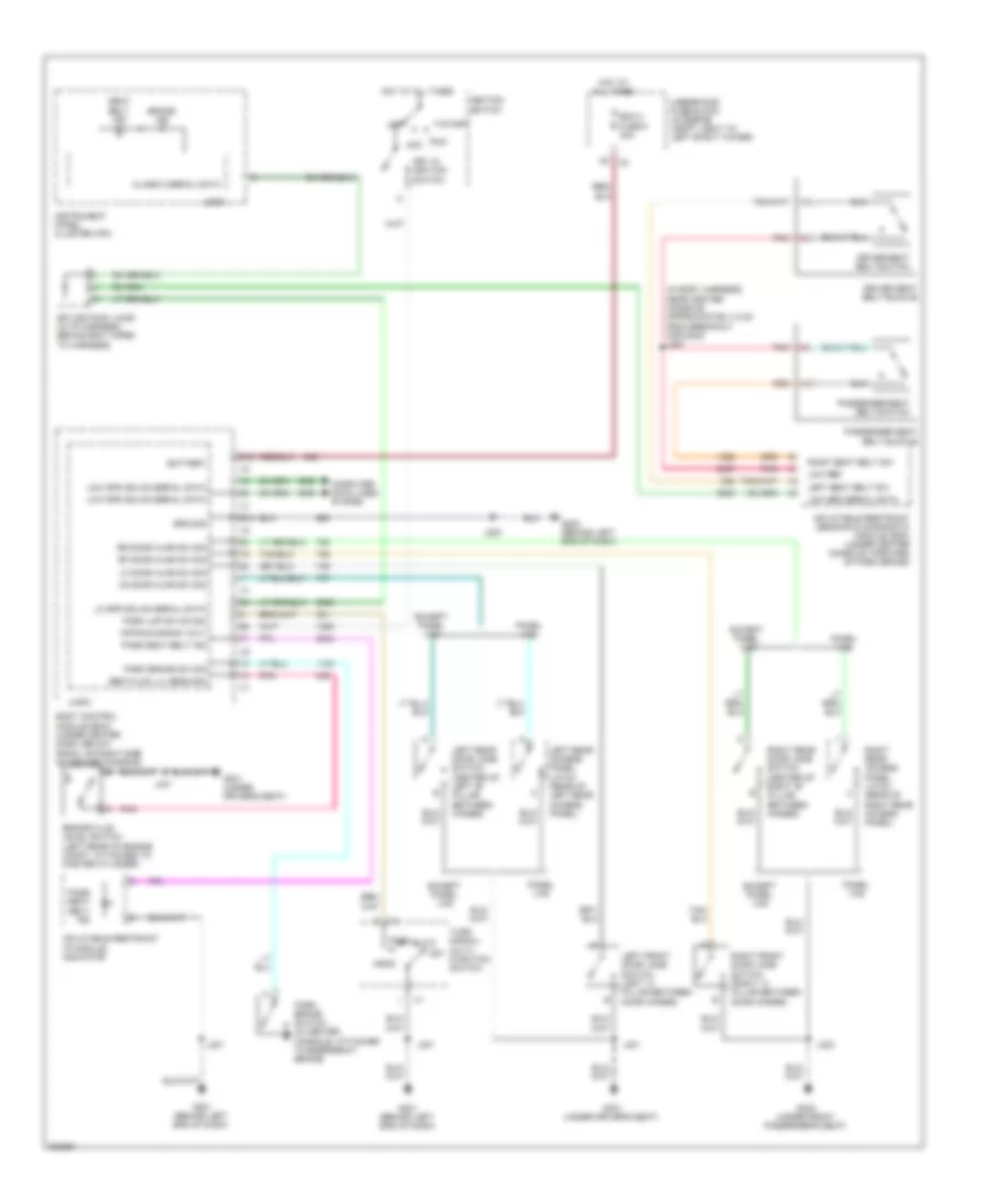
HEADLIGHTS
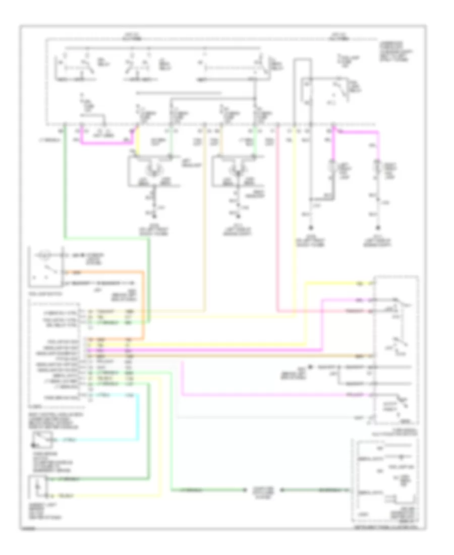
Headlights Wiring Diagram for Chevrolet HHR SS 2009
List of elements for Headlights Wiring Diagram for Chevrolet HHR SS 2009:
- (not used)
- Ambient light sensor (on top center of dash)
- Auto
- Body control module (bcm) (under center dash, below radio, on right side of center console)
- Computer data lines system
- Driver information center (dic) display
- Drl fuse 10a
- Drl relay
- Drl relay ctrl
- Fog lamp fuse 15a
- Fog lamp ind
- Fog lamp relay
- Fog lamp switch
- Fog lmp rly ctrl
- Fog lmp sw sig
- Ftp
- Ftp sw sig
- G109 (on left front shock tower)
- G111 (left side of engine compt)
- G201 (behind left end of dash)
- Head
- Headlamp dimmer sw
- Headlamp sw off sig
- Headlamp sw on sig
- Headlamp sw sig
- Hi beam relay
- Hi beam rly ctrl
- High beam
- High beam ind
- Hot at all times
- Ign
- Instrument panel cluster (ipc)
- Interior lights system
- J101
- J102
- J201
- Left front fog lamp
- Left headlamp
- Lo beam relay
- Logic
- Low
- Low beam
- Lt hi beam fuse 10a
- Lt lo beam fuse 10a
- Lt sens low ref
- Lt sens sig
- Off
- Park
- Park brake switch (in center console, attached to emergency brake)
- Park brk sw sig
- Right front fog lamp
- Right headlamp
- Rt hi beam fuse 10a
- Rt lo beam fuse 10a
- Serial data
- Turn signal/ multi-function switch
- Underhood fuse block (in engine compt, next to left strut tower)
HORN
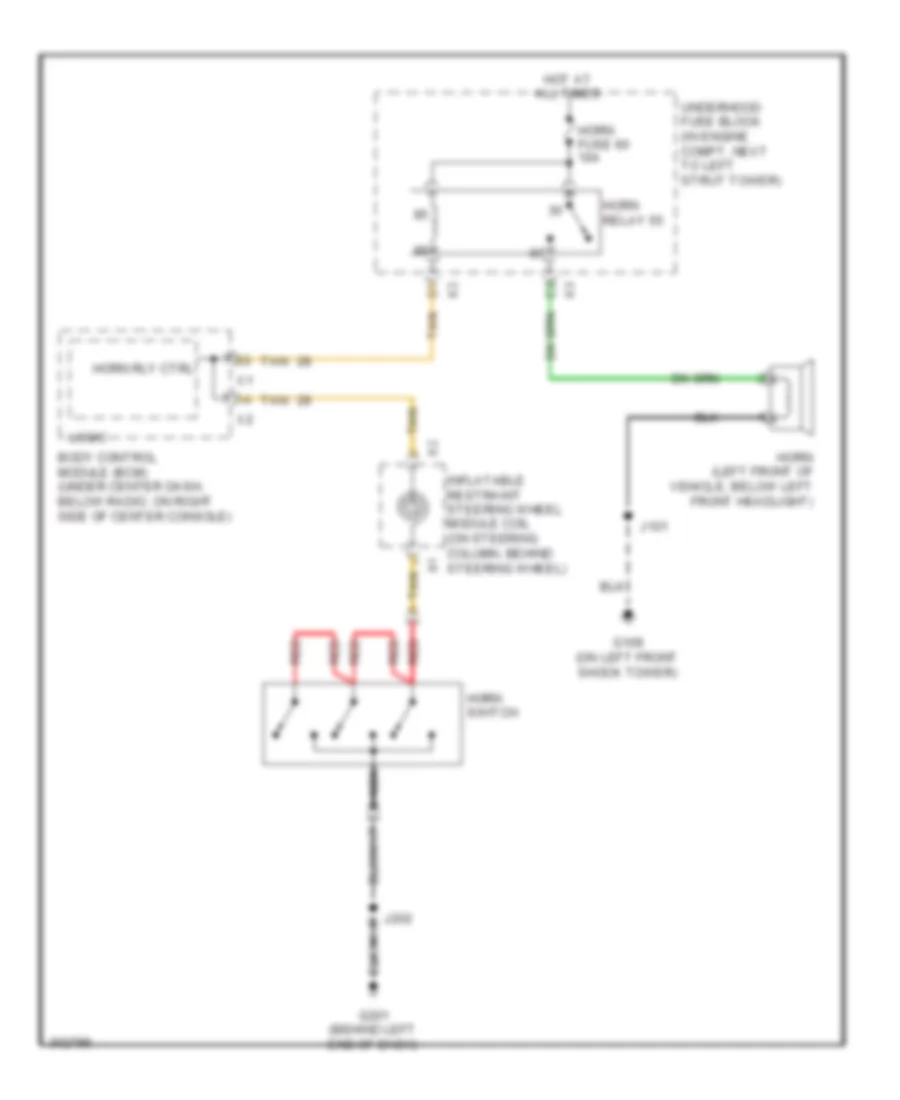
Horn Wiring Diagram for Chevrolet HHR SS 2009
List of elements for Horn Wiring Diagram for Chevrolet HHR SS 2009:
- Body control module (bcm) (under center dash, below radio, on right side of center console)
- G109 (on left front shock tower)
- G201 (behind left end of dash)
- Horn (left front of vehicle, below left front headlight)
- Horn fuse 60 10a
- Horn relay 55
- Horn rly ctrl
- Horn switch
- Hot at all times
- Inflatable restraint steering wheel module coil (on steering column, behind steering wheel)
- J101
- J202
- Logic
- Nca
- Red
- Tan
- Underhood fuse block (in engine compt, next to left strut tower)
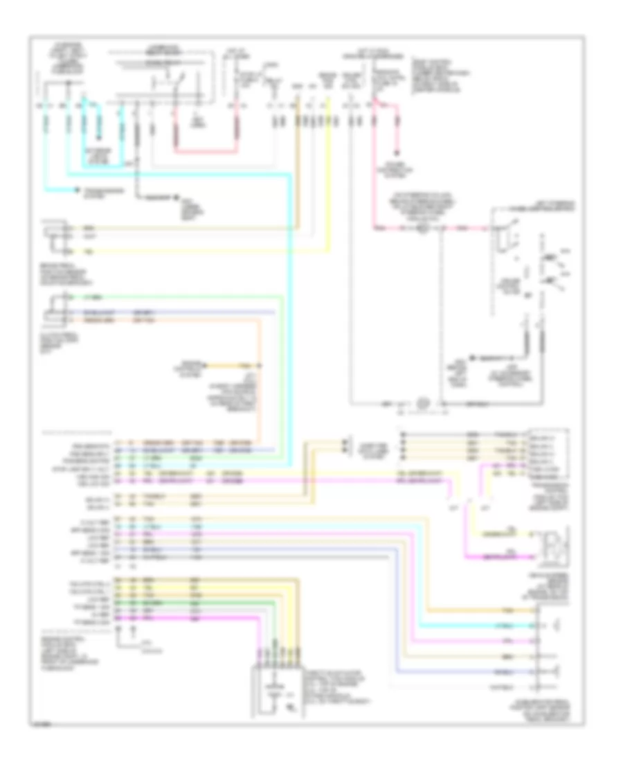
INSTRUMENT CLUSTER
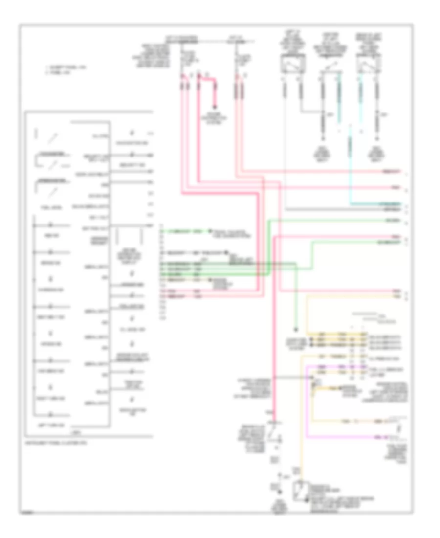
Instrument Cluster Wiring Diagram (1 of 2) for Chevrolet HHR SS 2009
List of elements for Instrument Cluster Wiring Diagram (1 of 2) for Chevrolet HHR SS 2009:
- (center
- (in body harness main bundle, approximately 15 cm rear of first breakout)
- (left "a" pillar between door hinges) left front door jamb switch
- (rear of left rear access panel) left rear access panel latch
- 2.0l
- 2.2l & 2.4l
- Abs ind
- Air bag ind
- Backlighting ind
- Bat pos volt
- Body control module (bcm) (under center dash, below radio, on right side of center console)
- Brake fluid level switch (left rear of engine compt, attached to master cylinder)
- Brake ind
- Charging ind
- Clstr fuse 7 10a
- Computer data lines system
- Dic sw sig
- Door lock relay
- Driver information center (dic) display
- Engine control module (ecm) (left side of engine compt, in front of underhood fuse block)
- Engine controls system
- Engine coolant temperature ind
- Engine oil pressure (eop) switch (except 2.4l: left side of engine, above starter solenoid) (2.4l: lower left rear of engine block)
- Except panel van
- Fog lamp ind
- Fuel level
- Fuel lvl sens sig
- Fuel pump & sender assembly (inside fuel tank)
- G201 (behind left end of dash)
- G301 (under driver's seat)
- Gmlan
- Gmlan ser data+
- Gmlan ser data-
- Gmlan serial data
- Gnd
- High beam ind
- Hot at all times
- Hot w/ run/crnk relay energized
- Hvac/ ip ign fuse 16 10a
- Ign
- Ign 1 volt
- Instrument panel cluster (ipc)
- J201
- J211 (m/t) tan
- J301
- Left turn ind
- Logic
- Low ref
- Malfunction ind
- Message request
- Mil ctrl
- Of left "b" pillar between hinges) left rear door jamb switch
- Oil level ind
- Oil pres sw sig
- Panel van
- Pnk
- Power distribution system
- Right turn ind
- Seat belt ind
- Security ind
- Security ind sply volt
- Serial data
- Speedometer
- Tachometer
- Tan
- Traction off ind
- Trunk, tailgate, fuel doors system
- Up shift ind
Instrument Cluster Wiring Diagram (2 of 2) for Chevrolet HHR SS 2009
List of elements for Instrument Cluster Wiring Diagram (2 of 2) for Chevrolet HHR SS 2009:
- (center
- (rear of right rear access panel) right rear access panel latch
- (right "a" pillar between door hinges) right front door jamb switch
- Ambient air temperature sensor (behind right front headlight, on frame rail)
- Body control module (bcm) (under center dash, below radio, on right side of center console)
- Boost
- Boost gauge sig
- Brake fluid lvl
- Computer data lines system
- Display
- Driver information center (dic) (multiple info display)
- Except panel van
- G201 (behind left end of dash)
- G301 (under driver's seat)
- G302 (under front passenger's seat)
- Gmlan ser data
- Ground
- H x2
- Hi spd gmlan serial data bus (+)
- Ign
- Ignition voltage
- Inflatable restraint steering wheel module coil (on steering column, behind steering wheel)
- Interior lights system
- J301
- J302
- Left steering wheel control switch
- Lf dr ajar sw
- Logic
- Low ref
- Low spd gmlan serial data bus (-)
- Lr dr ajar sw
- Menu
- Of right "b" pillar between hinges) right rear door jamb switch
- Panel van
- Park brake sw
- Park brake switch (in center console, attached to emergency brake)
- Pnk
- Reset/ select
- Rf dr ajar sw
- Rr dr ajar sw
- Security ind sig
- Tan
- Temp sens sig
- Turbo charger boost gage (2.0l w/o multiple info display)
- X1 h
INTERIOR LIGHTS
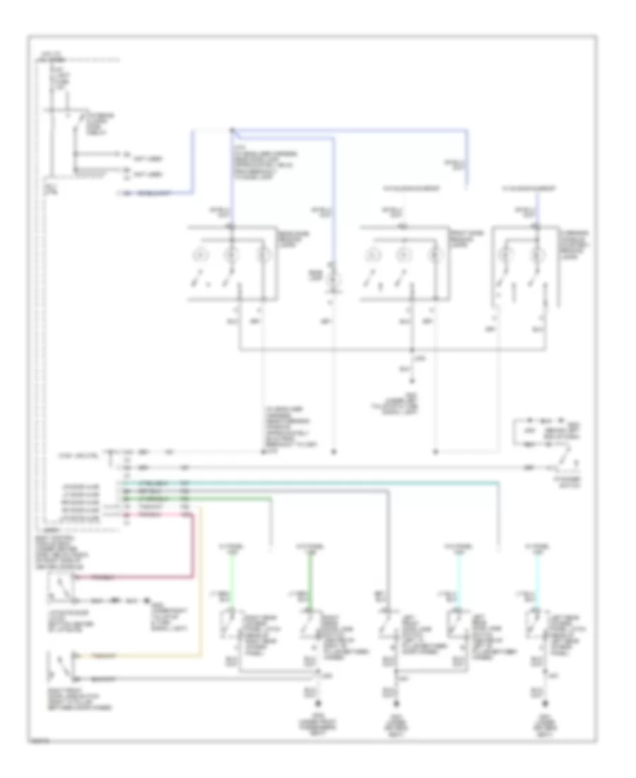
Courtesy Lamps Wiring Diagram for Chevrolet HHR SS 2009
List of elements for Courtesy Lamps Wiring Diagram for Chevrolet HHR SS 2009:
- (in headliner harness, near overhead console, approximately 26 cm from breakout to x397) j316
- (not used)
- A10
- Body control module (bcm) (under center dash, below radio, on right side of center console)
- Ctsy lps ctrl
- Dome lamp
- Front dome/ reading lamps
- G203 (behind left end of dash)
- G301 (under driver's seat)
- G302 (under front passenger's seat)
- G401 (under left tail/stop & turn signal light)
- G402 (under right tail/stop & turn signal light)
- Hot at all times
- I/p dimmer switch
- Int light fuse 10a
- Interior lamps pcb relay
- J200
- J301
- J302
- J303
- J310 (in headliner harness, near dome lamp, approximately 66 cm from breakout to dome lamp)
- J900
- Left front door jamb switch (left "a" pillar between door hinges)
- Left rear access panel latch (rear of left rear access panel)
- Left rear door jamb switch (center of left "b" pillar between hinges)
- Lf door ajar
- Liftgate ajar
- Liftgate door latch (bottom center of liftgate)
- Logic
- Lr door ajar
- Overhead console courtesy/ reading lamps
- Rear dome/ reading lamps
- Rf door ajar
- Right front door jamb switch (right "a" pillar between door hinges)
- Right rear access panel latch (rear of right rear access panel)
- Right rear door jamb switch (center of right "b" pillar between hinges)
- Rly ctrl
- Rr door ajar
- W/ panel van
- W/ sliding sunroof
- W/o panel van
- W/o sliding sunroof
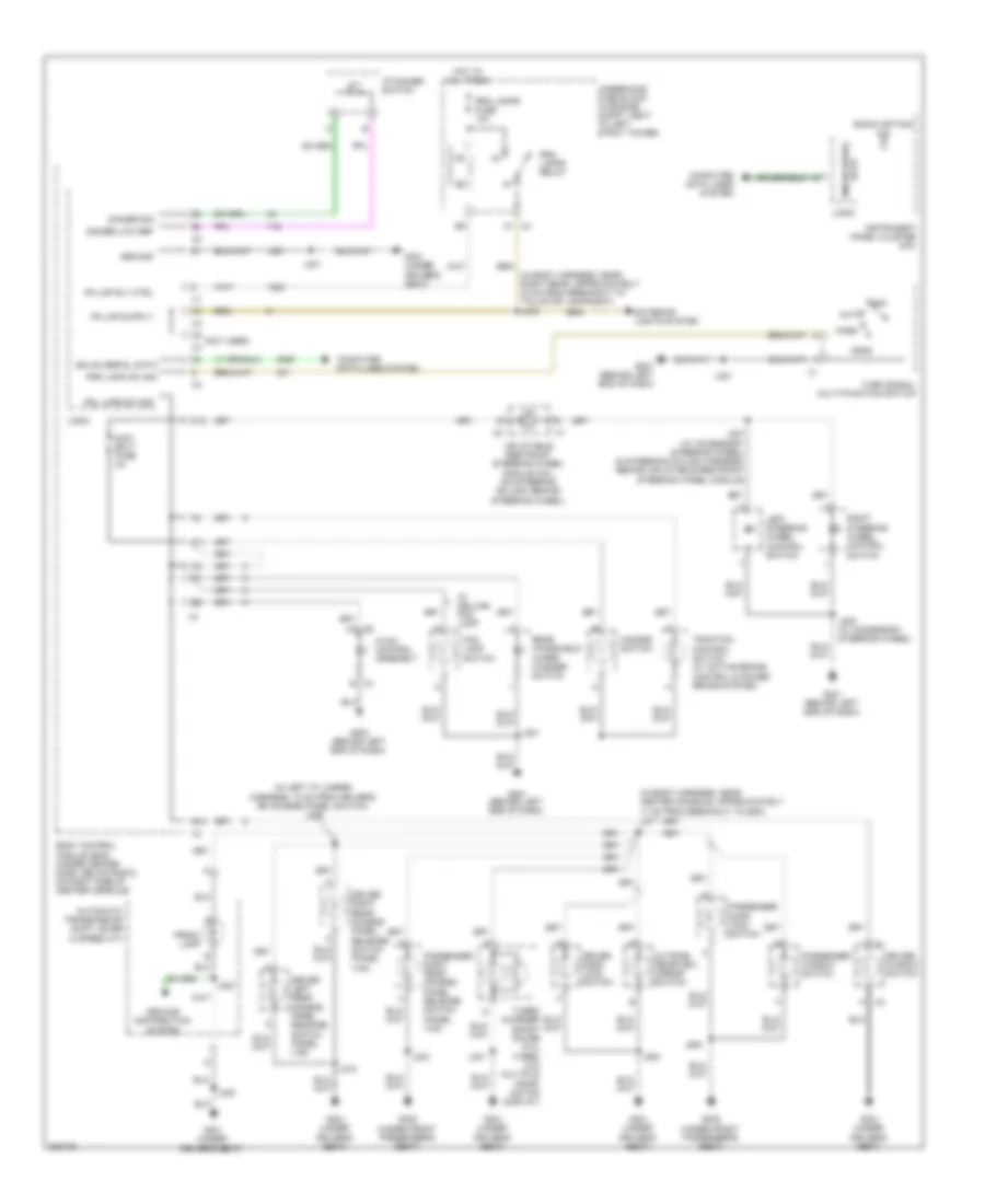
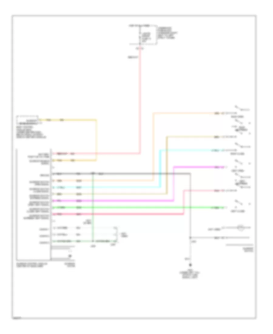
Instrument Illumination Wiring Diagram for Chevrolet HHR SS 2009
List of elements for Instrument Illumination Wiring Diagram for Chevrolet HHR SS 2009:
- (in body harness, near center console, approximately 11 cm from breakout to sdm) j311
- (in body harness, near right rear, approximately 33 cm from breakout to tail/stop lamp-right) j403
- (in left i/p jumper harness, 12 cm from driver's rr access panel switch) j209
- (not used)
- A x2
- Auto
- Automatic transmission shift lever (4 speed a/t)
- B12
- Backlighting ind
- Body control module (bcm) (under center dash, below radio, on right side of center console)
- C11
- C12
- Computer data lines system
- Dimmer low ref
- Dimmer sig
- Driver door lock switch
- Driver left rear access panel release switch (panel van)
- Driver right rear access panel release switch (panel van)
- Driver window switch
- Exterior lights system
- Fog lamp switch
- G201 (behind left end of dash)
- G203 (behind left end of dash)
- G301 (under driver's seat)
- G302 (under front passenger's seat)
- Gmlan serial data
- Ground
- Ground distribution system
- Hazard switch
- Head
- Hot at all times
- Hvac control assembly
- I/p dimmer switch
- Inflatable restraint steering wheel module coil (on steering column, behind steering wheel)
- Instrument panel cluster (ipc)
- J201
- J207 (w/ accessory steering wheel) (in steering column harness, behind inflatable restraint steering wheel module)
- J208 (w/ accessory steering wheel)
- J210
- J300
- J301
- J302
- J322
- J500
- J600
- Left steering wheel control switch
- Logic
- Off
- Outside rearview mirror switch
- Park
- Passenger door lock switch
- Passenger right rear access panel release switch (panel van)
- Passenger window switch
- Pk lmp rly ctrl
- Pnl lmps sw sig
- Prk lamp sw sig
- Prk lamps fuse 10a
- Prk lamps relay
- Prndl lamp
- Rear windshield wiper/ washer switch
- Right steering wheel control switch
- Swc bklt fuse 2a
- Traction control switch (w/ active brake control & power brake system)
- Turbo charger boost gauge (2.0l turbo w/o multiple infor- mation display)
- Turn signal/ multi-function switch
- Underhood fuse block (in engine compt, next to left strut tower)
- W/ deluxe fog lamp
- X3 b
- X4 a1
NAVIGATION
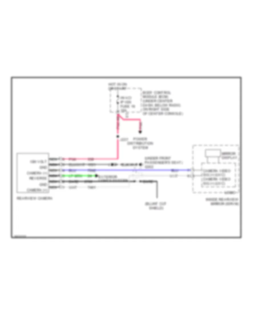
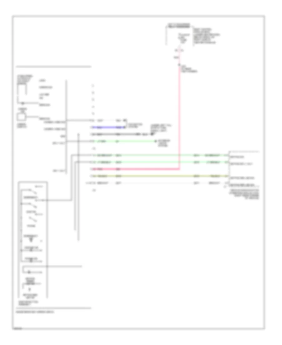
Rear View Camera Wiring Diagram for Chevrolet HHR SS 2009
List of elements for Rear View Camera Wiring Diagram for Chevrolet HHR SS 2009:
- (under front passenger's seat) g302
- Bare
- Body control module (bcm) (under center dash, below radio, on right side of center console)
- Camera video sig (+) (uvc) camera video sig (+) (uvc)
- Exterior lights system
- Hot in on or start
- Hvac/ ip ign fuse 16 10a
- Inside rearview mirror (isrvm)
- J237
- J302
- Logic
- Mirror display
- Nca ign volt nca gnd nca camera (+) nca reverse nca gnd nca camera (+)
- Pnk
- Power distribution system
- Rearview camera
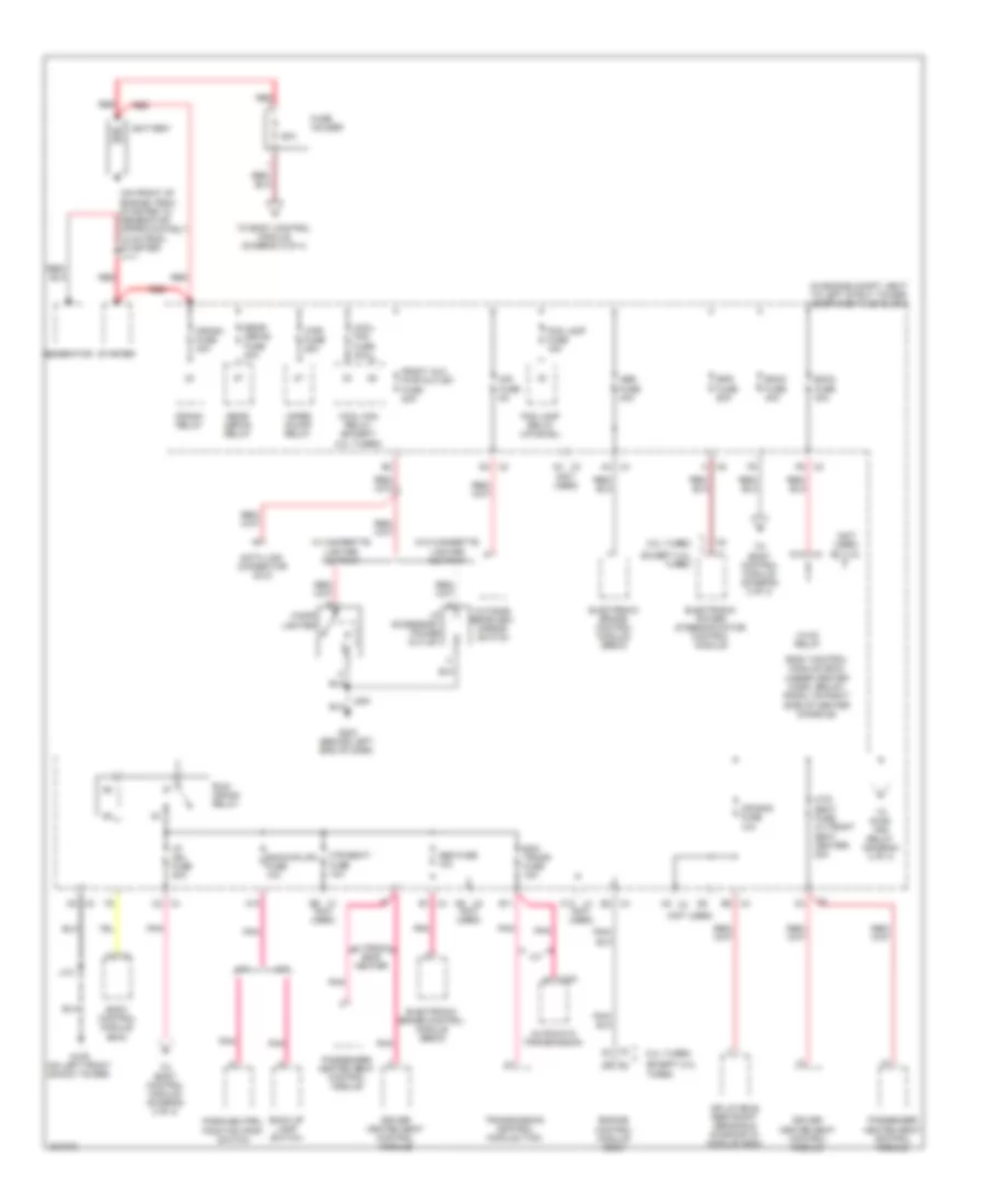
POWER DISTRIBUTION
Power Distribution Wiring Diagram (1 of 4) for Chevrolet HHR SS 2009
List of elements for Power Distribution Wiring Diagram (1 of 4) for Chevrolet HHR SS 2009:
- (in engine compt, next to left strut tower) underhood fuse block
- (not used)
- (on front of engine, from starter to generator approximately 15 cm from starter) j111
- 2.0l turbo
- 50a
- A/t
- A10
- A2 x3
- Abs fuse 10a
- Abs fuse 40a
- Air bag fuse 10a
- Automatic transmission
- B11
- Back up lamp switch
- Backup/lps fuse 10a
- Battery
- Bcm2 fuse 40a
- Bcm3 fuse 30a
- Body control module (bcm)
- Body control module (bcm) (under center dash, below radio, on right side of center console)
- Cigar lighter
- Cool fan fuse 30a
- Cool fan relay (except 2.0l turbo)
- Crank fuse 30a
- Crank relay
- D10 x3
- Data link connector (dlc)
- Driver heated seat control module
- E2 x4
- Ecm trans fuse 15a
- Electronic brake control module (ebcm)
- Electronic power steering motor control module
- Engine control module (ecm)
- Eps fuse 60a
- Except 2.0l turbo
- Fog lamp fuse 15a
- Fog lamp relay (uplevel)
- Front aux pwr outlet fuse 20a
- Fuse holder
- G109 (on left front shock tower)
- G203 (behind left end of dash)
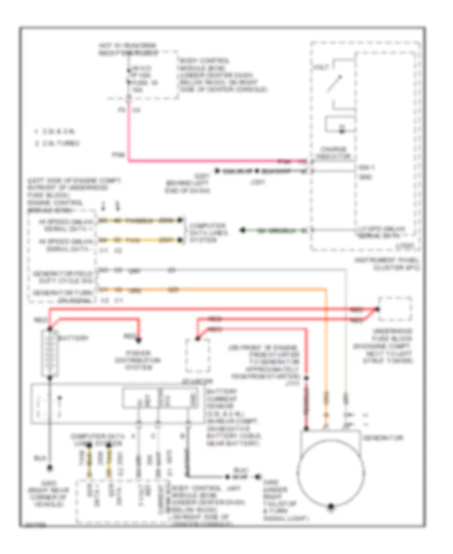
- Generator
- Htd/ seat fuse (w/ front seat heater) 20a
- Htd/seat/ fuse 10a
- Hvac relay
- I/p accessory power outlet
- I/p ign fuse 20a
- Inflatable restraint sensing & diagnostic module (sdm)
- J101
- M/t
- Mir fuse 5a
- Outside rearview mirror switch
- Park/neutral position (pnp) switch
- Passenger heated seat control module
- Pnk
- Rear defog fuse 40a
- Rear defog relay
- Red
- Run/ crank relay
- Starter
- To body control module (diagram 2 of 4)
- To body control module (diagram 3 of 4)
- To pwr/ trn relay (diagram 4 of 4)
- Transmission control module (tcm)
- W/ cigarette lighter ashtray
- W/ front seat heater
- W/o cigarette lighter ashtray
- Wiper on/off relay
- Wpr fuse 25a
- X1 b9 (not used)
- X1 c12
- X100 e
- X2 d3
- X2 f6
- X3 a3
- X3 c5
- X3 d6 (not used)
- X4 a4
- X4 b1
- X4 c2
- X4 e2
- X4 e6
- X6 a
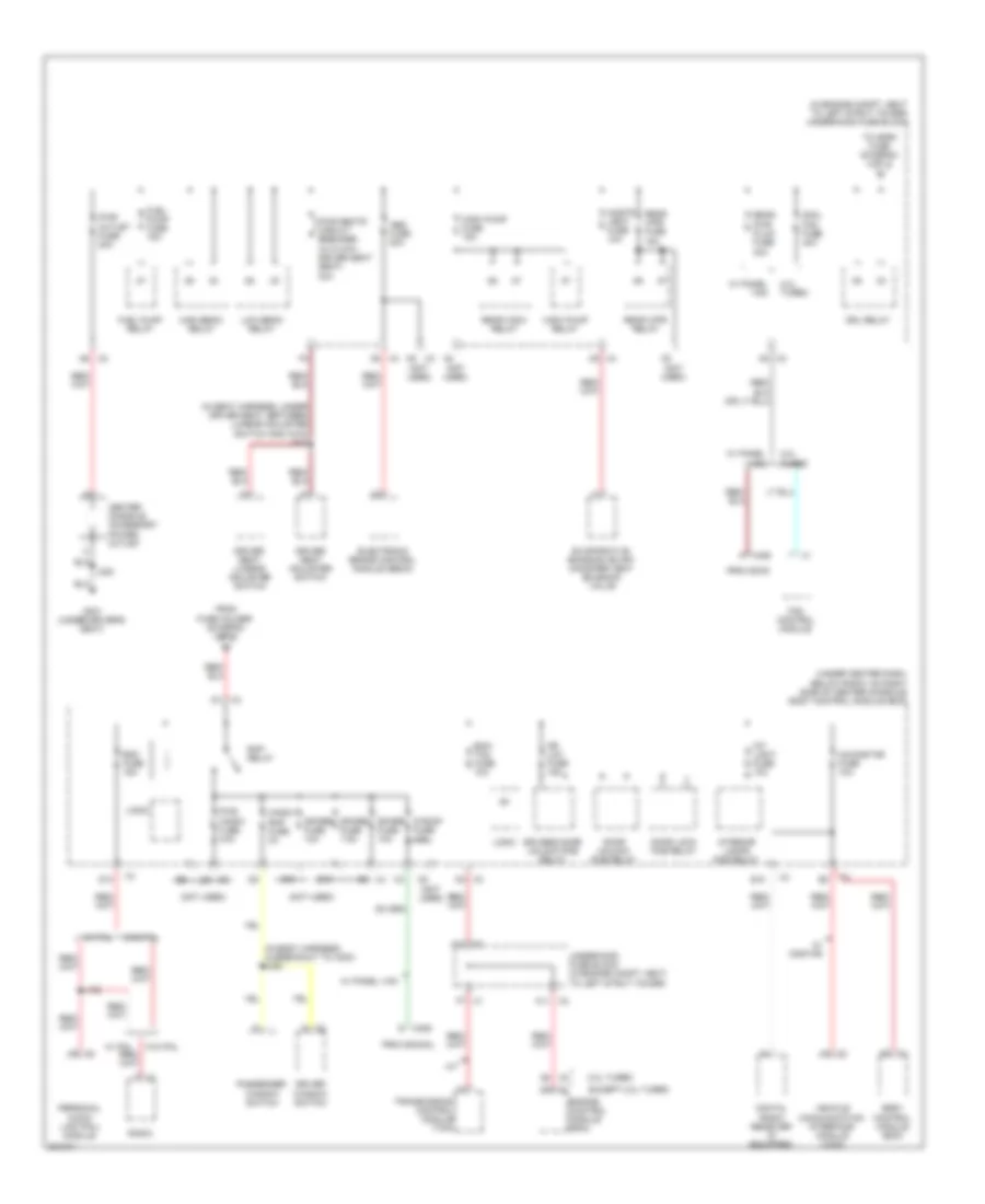
Power Distribution Wiring Diagram (2 of 4) for Chevrolet HHR SS 2009
List of elements for Power Distribution Wiring Diagram (2 of 4) for Chevrolet HHR SS 2009:
- (in body harness, in breakout to x203) j328
- (in engine compt, next to left strut tower) underhood fuse block
- (in seat harness, under driver seat, between lumbar adjuster switch and x315) j313
- (not used)
- (under center dash, below radio, on right side of center console) body control module (bcm)
- 2.0l turbo
- A x406
- A/t
- A10 x2
- A11 x2
- A5 x2
- A5 x3
- A5 x4
- A9 x2
- Abs fuse 20a
- B10
- Body control module (bcm)
- C10
- C5 x4
- Center console accessory power outlet
- Cnstr vent fuse 10a
- Cool fan fuse 40a
- D x406
- D1 x3
- D10
- D3 (not used)
- Digital radio receiver (if equipped)
- Door lock pcb relay
- Door unlock pcb relay
- Dr lck fuse 15a
- Driver seat adjuster switch
- Driver seat lumbar adjuster switch
- Driver window switch
- Drivers door unlock pcb relay
- Drl relay
- E10
- Ecm/ tcm fuse 10a
- Electronic brake control module (ebcm)
- Engine control module (ecm)
- Evaporative emission (evap) canister vent solenoid valve
- Except 2.0l turbo
- F7 x1
- Fan control module
- From fuse holder (diagram 1 of 4)
- Fuel pump fuse 15a
- Fuel pump relay
- G x2
- G301 (under driver's seat)
- High beam relay
- Int light fuse 10a
- Interior lamps pcb relay
- J196
- J300
- Logic
- Low beam relay
- Passenger window switch
- Personal audio link (pal) module
- Provision
- Provisional
- Pwr outlet fuse 20a
- Pwr seats circuit breaker (w/ 6 way driver seat seat) 30a
- Pwr wndw fuse 30a
- Radio
- Rap relay
- Rdo fuse 15a
- Rear pwr plug fuse 40a
- Rear wpr fuse 15a
- Rear wpr relay
- Rear wsw relay
- S roof fuse 15a
- Spare fuse 10a
- Spare fuse 7.5a
- To horn fuse (diagram 4 of 4)
- Transmission control module (tcm)
- Underhood fuse block (in engine compt, next to left strut tower)
- Vehicle communication interface module (vcim)
- W/ onstar
- W/ pal
- W/ panel van
- W/o pal
- Wndw rap fuse 2a
- Wsw pump fuse 15a
- Wsw pump relay
- X3 c5
- X3 d4
- X4 e8
- Xm/onstar fuse 10a
Power Distribution Wiring Diagram (3 of 4) for Chevrolet HHR SS 2009
List of elements for Power Distribution Wiring Diagram (3 of 4) for Chevrolet HHR SS 2009:
- (in body harness, approximately 10 cm from bcm breakout) j324
- (in i/p harness near ignition switch, approximately 4 cm from inflatable steering wheel coil module) j206
- (not used)
- (under center dash, below radio, on right side of center console) body control module (bcm)
- 10a
- 2.0l turbo
- A/t
- A8 x3
- Acc
- Air bag fuse 10a
- Alo
- Amp fuse 20a
- Asa
- Audio amplifier
- B provisional x406
- Chmsl relay
- Clstr fuse 10a
- D11
- D12 x3
- Driver information center (dic)
- Driver information center (dic) display
- Eps/str whl cntrl fuse 2a
- Except 2.0l turbo
- From underhood fuse block (diagram 1 of 4)
- Hvac control assembly
- Hvac/ ip ign fuse 10a
- Hvac/ pk3 + fuse 10a
- Ign sw/pk3 + fuse 2a
- Ignition lock cylinder control
- Ignition switch
- Inflatable restraint front passenger presence system (pps) module
- Inflatable restraint i/p module
- Inflatable restraint sensing & diagnostic module (sdm)
- Inflatable restraint steering wheel module coil
- Inflatable restraint vehicle rollover sensor
- Inside rearview mirror
- Instrument panel cluster (ipc)
- J327
- Key-in ignition switch
- Left steering wheel control switch
- Logic
- M/t
- Nca
- Off
- Pnk
- Power steering control module (pscm)
- Provisional fuse holder
- Rear view camera
- Run
- Start
- Stop lp fuse 10a
- Theft deterrent module (tdm)
- Theft deterrent module (tdm) actuator
- Turbo charger boost gage
- Underhood fuse block (diagram 1 of 4)
- Underhood relay block
- W/ enhanced audio speaker system
- W/ mulitiple information display
- W/ panel van
- W/ rear- view camera
- W/ rearview mirror
- W/ roof
- W/o rear- view camera
- W/o roof
- Windshield wiper/ washer switch
- Wpr fuse 10a
- X1 c
- X2 c
- X3 a6
- X4 d3
- X4 e6
- X4 f5
Power Distribution Wiring Diagram (4 of 4) for Chevrolet HHR SS 2009
List of elements for Power Distribution Wiring Diagram (4 of 4) for Chevrolet HHR SS 2009:
- (in body harness main bundle, approximately 65 cm rear of first breakout) j323
- (in body harness, 7.5 cm after breakout to x105 & x109) j113
- (in engine compt, next to left strut tower)
- (in engine harness) j121
- (in engine harness, near left rear of engine, approximately 8 cm from breakout to evaporative emission (evap) canister purge solenoid valve) (except 2.0l turbo) j106
- (in fuel injector harness, on top of engine) j104
- (not used)
- 2.0l turbo
- A/c clutch relay
- A/c fuse 10a
- A11
- B10
- D5 x2
- Driver window switch
- Ecm fuse 20a
- Engine control module (ecm)
- Evaporative emission (evap) canister purge solenoid valve
- Except 2.0l turbo
- Exh fuse 10a
- Exhaust camshaft position (cmp) actuator solenoid
- From drl relay (diagram 2 of 4)
- From htd/ c seat fuse (diagram 1 of 4)
- Fuel injector
- G302 (under front passenger's seat)
- Heated oxygen sensor (ho2s) 1
- Heated oxygen sensor (ho2s) 2
- Horn fuse 10a
- Horn relay
- Ignition coil 1
- Ignition coil 2
- Ignition coil 3
- Ignition coil 4
- Inj ign mdl fuse 15a
- Intake camshaft position (cmp) actuator solenoid
- J117 (2.0l turbo) (in engine harness, approximately 6 cm from breakout to ignition coil 2)
- Late prodution & 2.0l turbo
- Left rear access panel relay
- Left rear window switch
- Liftgate relse relay
- Liftgate/ s/roof/ fuse 20a
- Mass air flow (maf)/ intake air temperature (iat) sensor
- Nca
- Passenger window switch
- Pertn fuse (2.0l turbo) 10a
- Pnk
- Prk lamps fuse 10a
- Prk lamps relay
- Pwr window/ doors fuse 30a
- Pwr/trn relay
- Rear access panel fuse block (right rear of cargo area)
- Rear accessory power outlet
- Rear aux pwr outlet fuse (w/ panel van) 20a
- Right rear access panel relay
- Right rear window switch
- Sunroof control module (if equipped)
- Turbo charger by pass valve solenoid
- Turbo charger wastegate solenoid
- Underhood fuse block
- Vac pump fuse 20a
- Vac pump relay
- W/ panel van
- W/o panel van
- X1 b12
- X1 d9
- X1 f12
- X2 b10
- X2 c12
- X2 h
- X4 f6
POWER DOOR LOCKS
Power Door Locks Wiring Diagram for Chevrolet HHR SS 2009
List of elements for Power Door Locks Wiring Diagram for Chevrolet HHR SS 2009:
- (not used) b
- Ajar switch
- Antenna
- B(+)
- Body control module (bcm) (under center dash, below radio, on right side of center console)
- Clstr fuse 7 10a
- Coax
- D10
- Door lock ctrl
- Door lock pcb relay
- Door unlock ctrl
- Door unlock pcb relay
- Dr door unlock ctrl
- Dr door unlock pcb relay
- Dr lck fuse 26 15a
- Driver door latch (rear of driver's door)
- Driver door lock switch
- E12
- Except panel van
- Exterior lights system
- G201 (behind left end of dash)
- G203 (behind left end of dash)
- G301 (under driver's seat)
- G302 (under front passenger's seat)
- G402 (under right tail/stop & turn signal light)
- Gmlan
- Gmlan serial data
- Ground
- Horn relay ctrl
- Horns system
- Hot at all times
- Instrument panel cluster (ipc)
- Interior lights system
- J200
- J201
- J212
- J301
- J302
- J500
- J600
- J900
- Keyless entry
- Left front door jamb switch (left "a" pillar between door hinges)
- Left rear access panel latch (rear of left rear access panel)
- Left rear door jamb switch (center of left "b" pillar between hinges)
- Left rear door latch (except panel van) (rear of left rear door)
- Lf dr ajar sw sig
- Liftgate ajar sw sig
- Liftgate door latch (bottom center of liftgate)
- Liftgate release switch
- Lock
- Lock/unlock sig
- Logic
- Lr dr ajar sw sig
- Panel van
- Park lamp rly ctrl
- Passenger door latch (rear of front passenger's door)
- Passenger door lock switch
- Power distribution system
- Rdo fuse 23 15a
- Rear door lock switch
- Release sw sig
- Remote control door lock receiver (rcdlr) (front center of headliner)
- Rf dr ajar sw sig
- Right front door jamb switch (right "a" pillar between door hinges)
- Right rear access panel latch (rear of right rear access panel)
- Right rear door jamb switch (center of right "b" pillar between hinges)
- Right rear door latch (except panel van) (rear of right rear door)
- Rr dr ajar sw sig
- Serial data
- Splice pack jx205 (in i/p harness, behind bcm taped to harness)
- Tan
- Trunk, tailgate, fuel doors system
- Unlock
POWER MIRRORS
Automatic Day/Night Mirror Wiring Diagram for Chevrolet HHR SS 2009
List of elements for Automatic Day/Night Mirror Wiring Diagram for Chevrolet HHR SS 2009:
- (if equipped) automatic day/night mirror
- (under left tail/ stop & turn signal light) g401
- Body control module (bcm) (under center dash, below radio, on right side of center console)
- Camera video sig
- Emergency
- Emergency ind
- Exterior lights system
- Gnd
- Hot w/ run/crank relay energized
- Hvac/ip ign fuse 10a
- Ign
- Ign 1 volt
- Inside rearview mirror (isrvm)
- J303
- J327 (w/ rear view camera)
- Keypad green led ind
- Keypad red led ind
- Keypad red led sig
- Keypad sig
- Keypad sply volt
- Logic
- Low ref
- Mirror display
- Mirror ind
- Mirror sig
- Navigation system
- Onstar
- Onstar button assembly
- Onstar ind
- Phone
- Phone ind
- Pnk
- Sens sig
- Sply volt
- Vehicle communication interface module (vcim) (right rear corner of vehicle)
Power Mirrors Wiring Diagram for Chevrolet HHR SS 2009
List of elements for Power Mirrors Wiring Diagram for Chevrolet HHR SS 2009:
- Down
- Driver
- Driver outside rearview mirror (front of driver's door)
- G301 (under driver's seat)
- Hot at all times
- Interior lights system
- J500
- Left
- Left/ right
- Mir fuse 5a
- Nca
- Outside rearview mirror switch
- Passenger
- Passenger outside rearview mirror (front of front passenger's door)
- Right
- Underhood fuse block (in engine compt, next to left strut tower)
- Up/ down
POWER SEATS
Driver Power Seat Wiring Diagram for Chevrolet HHR SS 2009
List of elements for Driver Power Seat Wiring Diagram for Chevrolet HHR SS 2009:
- Driver seat adjuster switch
- Driver seat front vertical motor (under left side of driver's seat)
- Driver seat horizontal motor (under right side of driver's seat)
- Driver seat rear vertical motor (under right side of driver's seat)
- Front
- Fwd
- G301 (under driver's seat)
- Hot at all times
- J313
- J314
- Nca
- Pwr seats circuit breaker 37 30a
- Rear dn
- Rear up
- Rwd
- Underhood fuse block (in engine compartment, next to left strut tower)
Driver"s Lumbar Wiring Diagram for Chevrolet HHR SS 2009
List of elements for Driver"s Lumbar Wiring Diagram for Chevrolet HHR SS 2009:
- Deflate
- Driver seat lumbar adjuster switch
- Driver seat lumbar motor (right side of driver's seat back)
- F4 x4
- G301 (under driver's seat)
- Hot at all times
- Inflate
- J313
- J314
- Nca
- Pwr seats circuit breaker 37 30a
- Tan
- Underhood fuse block (in engine compartment, next to left strut tower)
Heated Seats Wiring Diagram for Chevrolet HHR SS 2009
List of elements for Heated Seats Wiring Diagram for Chevrolet HHR SS 2009:
- (under front passenger's seat)
- Batt pos volt
- Driver heated seat back element (in driver's seat back)
- Driver heated seat control module (under front center of driver seat)
- Driver heated seat cushion element (in driver's seat cushion)
- Driver heated seat hi ind
- Driver heated seat hi/lo ind
- Driver heated seat hi/lo signal
- Driver heated seat lo ind
- Driver heated seat switch
- Drv heat hi ind ctrl
- Drv heat low ind ctrl
- Drv hi temp ind ctrl
- Drv hi/low sig
- Drv low temp ind ctrl
- G301 (under driver's seat)
- G302
- Gnd
- Heat hi ind ctrl
- Heat low ind ctrl
- Hi/low sig
- Hot at all times
- Hot w/ run/crank relay energized
- Htd seat fuse 47 10a
- Htd/ seat fuse 23 20a
- Hvac control module
- Ign 1 volt
- J314
- J315
- Logic
- Nca
- Pass hi temp ctrl
- Pass hi/low sig
- Pass low temp ctrl
- Passenger heated seat back element (in front passenger's seat back)
- Passenger heated seat control module (under front center of front passenger's seat)
- Passenger heated seat cushion element (in front passenger's seat cushion)
- Passenger heated seat hi ind
- Passenger heated seat hi/lo ind
- Passenger heated seat hi/lo signal
- Passenger heated seat lo ind
- Passenger heated seat switch
- Pnk
- Seat element sply
- Tan
- Temp sens sig
- Underhood fuse block (in engine compartment, next to left strut tower)
POWER TOP/SUNROOF
Power Top/Sunroof Wiring Diagram for Chevrolet HHR SS 2009
List of elements for Power Top/Sunroof Wiring Diagram for Chevrolet HHR SS 2009:
- (not used)
- Battery positive voltage
- Body control module (bcm) (under center dash, below radio, on right side of center console)
- C5 x2
- Config 1
- Config 2
- Config 3
- Enable signal
- G401 (under left tail/ stop & turn signal light)
- Ground
- Hot at all times
- J303
- J308
- J309
- L/gate/ s/roof fuse 10 20a
- Pnk
- Roof close
- Roof express
- Roof open
- Sunroof
- Sunroof control module (center of headliner)
- Sunroof enable signal
- Sunroof motor
- Sunroof switch
- Sunroof switch close signal
- Sunroof switch close vent signal
- Sunroof switch express signal
- Sunroof switch express vent signal
- Sunroof switch open signal
- Sunroof switch open vent signal
- Tan
- Underhood fuse block (in engine compt, next to left strut tower)
- Vent close
- Vent express
- Vent open
- X397
POWER WINDOWS
Power Windows Wiring Diagram for Chevrolet HHR SS 2009
List of elements for Power Windows Wiring Diagram for Chevrolet HHR SS 2009:
- Acc pwr sply volt
- Body control module (bcm) (under center dash, below radio, on right side of center console)
- Dimmer sw sig
- Down
- Driver window motor (in driver's door)
- Driver window switch
- Drv mtr dn ctrl
- Drv mtr up ctrl
- G301 (under driver's seat)
- G302 (under front passenger's seat)
- Ground
- Hot at all times
- Hot w/ rap relay energized
- Interior lights system
- J300
- J323
- J328
- J600
- Left rear window motor (in left rear door)
- Left rear window switch
- Left rear window switch (w/o panel van)
- Logic
- Lr wind dn sig
- Lr wind mtr dn ctrl
- Lr wind mtr up ctrl
- Lr wind sw lk sig
- Lr wind up sig
- Mast sw lk sig
- Mast sw wind dn sig
- Mast sw wind up sig
- Pass mtr dn cntrl
- Pass mtr up cntrl
- Pass wind dn sig
- Pass wind up sig
- Passenger window motor (in front passenger's door)
- Passenger window switch
- Pwr wind dr sply
- Pwr wind fuse
- Pwr wind fuse sply
- Pwr window/doors fuse 36 30a
- Right rear window motor (in right rear door)
- Right rear window switch
- Right rear window switch (w/o panel van)
- Rr wind dn sig
- Rr wind mtr dn ctrl
- Rr wind mtr up ctrl
- Rr wind sw lk sig
- Rr wind up sig
- Tan
- Underhood fuse block (in engine compt, next to left strut tower)
- Wndw rap fuse 17 30a
RADIO
Radio Wiring Diagram, with Amplifier for Chevrolet HHR SS 2009
List of elements for Radio Wiring Diagram, with Amplifier for Chevrolet HHR SS 2009:
- (in body harness, right side of rear compt, approximately 5 cm from breakout to digital radio receiver)
- (right rear corner of vehicle) vehicle communication interface module (vcim)
- 10 volt ref
- Amp fuse 6 20a
- Antenna sig
- Audio amplifier (behind left rear quarterpanel)
- Audio common
- Audio common (u2k)
- Audio line module
- Bare
- Battery
- Battery positive voltage
- Body control module (bcm) (under center dash, below radio, on right side of center console)
- Coax
- Computer data lines system
- D10
- D11
- Digital radio receiver (right rear corner of vehicle)
- Drain wire
- G201 (behind left end of dash)
- G401 (under left tail/stop & turn signal light)
- Ground
- Hot at all times
- Inflatable restraint steering wheel module coil (on steering column, behind steering wheel)
- Interior lights system
- J195
- J195 (w/ pal)
- J196
- J204 (in i/p harness, near right side of i/p, approximately 2 cm from breakout to x206)
- J205 (in i/p harness, near right side of i/p, approximately 10 cm from x200)
- J317 (in body harness, near right side of i/p, approximately 8 cm from breakout to x200)
- J318 (in body harness, near right side of i/p, approximately 3 cm from j317)
- J405
- J407 (in body harness, in right rear, approximately 10 cm from vehicle communication interface module (vcim))
- L audio sig (+)
- Left audio sig (+)
- Left audio sig (+) (u2k)
- Left front speaker
- Left front tweeter speaker
- Left rear speaker
- Lf lo lev audio (+)
- Lf lo lev audio (-)
- Lf low lev audio (+)
- Lf low lev audio (-)
- Lf spkr out (+)
- Lf spkr out (-)
- Lo spd gmlan serial data
- Lr lo lev audio (-)
- Lr low lev audio (+)
- Lr low lev audio (-)
- Lr spkr out (+)
- Lr spkr out (-)
- Nca
- Personal audio link (pal) connector
- Personal audio link (pal) module
- Pnk
- Power distribution system
- R audio sig (+)
- Radio
- Radio antenna base (center front of headliner)
- Radio on sig
- Radio on signal
- Radio right audio
- Rdo fuse 23 15a
- Remote radio ctrl
- Remote radio ctrl sig
- Rf lo lev audio (+)
- Rf lo lev audio (-)
- Rf low lev audio (+)
- Rf low lev audio (-)
- Rf spkr out (+)
- Rf spkr out (-)
- Right audio sig (+) (u2k)
- Right front speaker
- Right front tweeter speaker
- Right rear speaker
- Right steering wheel control switch (w/ accessory steering wheel)
- Rr lo lev audio (+)
- Rr lo lev audio (-)
- Rr low lev audio (+)
- Rr low lev audio (-)
- Rr spkr out (+)
- Rr spkr out (-)
- Rr sub spkr out (+)
- Rr sub spkr out (-)
- Seek dn
- Seek up
- Serial data
- Steering wheel ctrl sig
- Sub spkr out (+)
- Sub spkr out (-)
- Subwoofer speaker
- Tan
- Telephone voice low ref
- Telephone voice signal
- Voice low ref
- Voice rec
- Voice signal
- Vol dn
- Vol up
- W/ personal
- W/o personal
Radio Wiring Diagram, without Amplifier for Chevrolet HHR SS 2009
List of elements for Radio Wiring Diagram, without Amplifier for Chevrolet HHR SS 2009:
- (on steering column, behind steering wheel) inflatable restraint steering wheel module coil
- (right rear corner of vehicle) vehicle communication interface module (vcim)
- 10 volt ref
- Antenna sig
- Audio common
- Audio common (u2k)
- Audio line module
- Bare
- Battery
- Body control module (bcm) (under center dash, below radio, on right side of center console)
- Coax
- Computer data lines system
- D10
- Digital radio receiver (right rear corner of vehicle)
- Drain wire
- G201 (behind left end of dash)
- Ground
- Hot at all times
- Interior lights system
- J195 (w/ pal)
- J196
- J204 (in i/p harness, near right side of i/p, approximately 2 cm from breakout to x206)
- J205 (in i/p harness, near right side of i/p, approximately 10 cm from x200)
- J317 (in body harness, near right side of i/p, approximately 8 cm from breakout to x200)
- J318 (in body harness, near right side of i/p, approximately 3 cm from j317)
- J405 (in body harness, right side of rear compt, approximately 5 cm from breakout to digital radio receiver)
- J407 (in body harness, in right rear, approximately 10 cm from vehicle communication interface module (vcim))
- L audio sig (+)
- Left audio sig (+)
- Left audio sig (+) (u2k)
- Left front speaker
- Left front tweeter speaker
- Left rear speaker
- Lf spkr out (+)
- Lf spkr out (-)
- Lo spd gmlan serial data
- Lr spkr out (+)
- Lr spkr out (-)
- Nca
- Personal audio link (pal) connector
- Personal audio link (pal) module
- Pnk
- Power distribution system
- R audio sig (+)
- Radio
- Radio antenna base (center front of headliner)
- Radio on sig
- Radio on signal
- Radio right audio
- Rdo fuse 23 15a
- Rf spkr out (+)
- Rf spkr out (-)
- Right audio sig (+) (u2k)
- Right front speaker
- Right front tweeter speaker
- Right rear speaker
- Right steering wheel control switch (w/ accessory steering wheel control)
- Rr spkr out (+)
- Rr spkr out (-)
- Seek dn
- Seek up
- Serial data
- Steering wheel ctrl sig
- Tan
- Telephone voice low ref
- Telephone voice signal
- Voice low ref
- Voice rec
- Voice signal
- Vol dn
- Vol up
- W/ personal
- W/o personal
Satellite Radio Wiring Diagram for Chevrolet HHR SS 2009
List of elements for Satellite Radio Wiring Diagram for Chevrolet HHR SS 2009:
- (near right side of i/p, approximately 2 cm from breakout to x206)
- (right rear corner of vehicle) digital radio receiver
- Ant sig
- Audio common
- Bare
- Battery volt
- Body control module (bcm) (under center dash, below radio, on right side of center console)
- Coax
- Computer data lines system
- Digital radio antenna (rear center of roof)
- Drain wire
- E10
- Fuse 24 10a
- G402 (under right
- Gmlan serial data
- Ground
- Hot at all times
- J204
- J317 (near right side of i/p, approximately 8 cm from breakout to x200)
- J401
- J405 (right side of rear compt, approximately 5 cm from breakout to digital radio receiver)
- L audio (+)
- L audio sig (+)
- Low speed
- Onstar
- R audio (+)
- R audio sig (+)
- Radio
- Serial data
- Tail/stop & turn signal light)
- Xm/
SHIFT INTERLOCK
Shift Interlock Wiring Diagram for Chevrolet HHR SS 2009
List of elements for Shift Interlock Wiring Diagram for Chevrolet HHR SS 2009:
- 5 volt ref
- A/t shift lever position ind
- A/t shift lock control solenoid
- Acc
- Accessory voltage
- Automatic transmission shift lever
- Body control module (bcm) (under center dash, below radio, on right side of center console)
- Brake pedal pos sens signal
- Brake pedal position sensor (on brake pedal mounting bracket)
- C8 x4
- G301 (under driver's seat)
- Hot at all times
- Ignition lock cylinder control actuator (in steering column, part of ignition lock cylinder)
- Ignition switch
- Interior lights system
- J206
- J300
- J322
- Logic
- Low ref
- Nca
- Off
- Park position switch
- Run
- Start
STARTING/CHARGING
Charging Wiring Diagram for Chevrolet HHR SS 2009
List of elements for Charging Wiring Diagram for Chevrolet HHR SS 2009:
- (left side of engine compt, in front of underhood fuse block) engine control module (ecm)
- (on front of engine, from starter to generator approximately 15cm from starter) j111
- 2.0l turbo
- 2.2l & 2.4l
- 5 volt ref
- 5v ref
- Battery
- Body control module (bcm) (under center dash, below radio, on right side of center console)
- Charge indicator
- Computer data lines system
- Data +
- Data - ser
- G201 (behind left end of dash)
- G402 (under right tail/stop & turn signal light)
- G403 (right rear corner of vehicle)
- Generator
- Generator field duty cycle sig
- Generator turn on signal
- Gnd
- Hi speed gmlan serial data +
- Hi speed gmlan serial data - x1
- Hot w/ run/crnk relay energized
- Hvac/ ip ign fuse 16 10a
- Ign 1
- Instrument panel cluster (ipc)
- J201
- J401
- Lo spd gmlan serial data
- Logic
- Pnk
- Power distribution system
- Red
- Sens sig current
- Ser
- Sig sens
- Starter
- Tan
- Underhood fuse block (in engine compt, next to left strut tower)
- Volt
- X4 f6
Starting Wiring Diagram for Chevrolet HHR SS 2009
List of elements for Starting Wiring Diagram for Chevrolet HHR SS 2009:
- 2.0l turbo
- 2.2l & 2.4l
- Acc
- Battery
- Body control module (bcm) (under center dash, below radio, on right side of center console)
- Charging circuit
- Clutch st neutral st sig park/neutral sig
- Computer data lines system
- Crnk fuse 5 30a
- Crnk relay 34
- Engine control module (ecm) (left side of engine compt, in front of underhood fuse block)
- G107 (on front left corner of transmission)
- G403 (right rear corner of vehicle)
- Hi speed gmlan serial data +
- Hi speed gmlan serial data -
- Hot at all times
- Ign key sig
- Ignition switch
- J103
- Logic
- Off
- Off/run/crank voltage
- Park/neutral position (pnp) switch (4 speed a/t) (top of automatic transmission)
- Power distribution system
- R n
- Red
- Run
- Start
- Starter enable relay control
- Starter motor
- Tan
- Underhood fuse block (in engine compt, next to left strut tower)
SUPPLEMENTAL RESTRAINTS
Supplemental Restraints Wiring Diagram (1 of 2) for Chevrolet HHR SS 2009
List of elements for Supplemental Restraints Wiring Diagram (1 of 2) for Chevrolet HHR SS 2009:
- (in body harness, approximately 10 cm from bcm breakout)
- (on lower corner of front passenger's door)
- (under center console, near sdm module) g306
- Air bag fuse 10a
- Air bag fuse 56 10a
- Batt positive voltage
- Body control module (bcm) (under center dash, below radio, on right side of center console)
- Gmlan serial data
- Ground
- High control
- Hot at all times
- Hot in run or start
- Hvac/ ip/ign fuse 16 10a
- Ignition 1 voltage
- Ind
- Inflatable restraint instrument panel (i/p) module (right side of dash, above glove compt)
- Inflatable restraint sensing & diagnostic module (sdm) (under center console, forward of park brake)
- Inflatable restraint steering wheel module (in steering wheel)
- Inflatable restraint steering wheel module coil (on steering column, behind steering wheel)
- J324
- J325 (in body harness, approximately 10 cm from inflatable restraint rollover sensor)
- Left inflatable restraint side impact sensor (sis) (if equipped) (on lower corner of driver's door)
- Left seat belt pretensioner (base of left "b" pillar)
- Left seat belt sw
- Left signal
- Left voltage
- Logic
- Low control
- Low ref
- Occupant sens sig
- Pnk
- Right inflatable restraint side impact sensor (sis) (if equipped)
- Right seat belt pretensioner (base of right "b" pillar)
- Right seat belt sw
- Right signal
- Right voltage
- Sensor signal
- Shorting bar
- Stage 1
- Stage 2
- Tan
- Underhood fuse block (in engine compt, next to left strut tower)
- W/ head curtain air bag
- W/o head curtain air bag
Supplemental Restraints Wiring Diagram (2 of 2) for Chevrolet HHR SS 2009
List of elements for Supplemental Restraints Wiring Diagram (2 of 2) for Chevrolet HHR SS 2009:
- (in i/p harness, behind bcm taped to harness) splice pack jx205
- (top center of radiator support, near hood latch)
- (under front passenger's seat) g302
- 5 volt ref
- Air bag ind
- Air bag off ind
- Air bag on ind
- Case ground
- Data link connector (dlc) (under lower left of dash)
- Driver seat belt buckle
- Driver seat belt switch
- G201 (behind left end of dash)
- G302 (under front passenger's seat)
- Gnd
- Ground
- Ign
- Ign 1 volt
- Ignition 1 voltage
- Inflatable restraint front end sensor
- Inflatable restraint front passenger presence system (pps) module (w/ child presence detector) (under front passenger's seat)
- Inflatable restraint front passenger presence system (pps) module (w/ self-contained air susp) (under front passenger's seat)
- Inflatable restraint front passenger presence system (pps) sensor (w/ child presence detector) (under front passenger's seat cushion)
- Inflatable restraint front passenger presence system (pps) sensor (w/ self-contained air susp) (under front passenger's seat cushion)
- Inflatable restraint i/p module indicator
- Inflatable restraint passenger seat belt tension sensor (w/ child presence detector) (base of right "b" pillar)
- Inflatable restraint vehicle rollover sensor
- Instrument panel cluster (ipc)
- J201
- J302
- J307 (in body harness, near center console, approximately 6 cm from breakout for g302)
- J325
- Left inflatable restraint roof rail module (if equipped) (above front & rear left door rails behind headliner)
- Logic
- Low ref
- Nca
- Occupant sens sig
- Off ind ctrl x1
- On ind ctrl
- Pass seat belt sens
- Pass sens sig
- Passenger air bag ind
- Passenger seat belt buckle
- Passenger seat belt ind
- Passenger seat belt switch
- Pnk
- Red
- Right inflatable restraint roof rail module (if equipped) (above front & rear right door rails behind headliner)
- Seat belt ind
- Serial data
- Shorting bar
- W/ child presence detector
- W/ self-contained air susp
TRANSMISSION
Transmission Wiring Diagram for Chevrolet HHR SS 2009
List of elements for Transmission Wiring Diagram for Chevrolet HHR SS 2009:
- 1-2 shift solenoid (ss) valve
- 1-2 ss vlv ctrl
- 2-3 shift solenoid (ss) valve
- 2-3 ss vlv ctrl
- A10
- A11 x2
- A12 x1
- Acc volt
- Acc voltage
- Automatic transmission
- Automatic transmission fluid pressure (tfp) manual valve position switch
- Automatic transmission fluid temperature (tft) sensor
- Automatic transmission input shaft speed (iss) sensor
- B(+)
- B11
- Body control module (bcm) (under center dash, below radio, on right side of center console)
- Computer data lines system
- D4 x3
- Drive
- Ecm trans fuse 15a
- Ecm/ tcm fuse 25 10a
- Engine controls system
- Exterior lights system
- F5 x4
- G107 (on front left corner of of transmission)
- G107 (on front left corner of transmission)
- Gmlan bus (+)
- Gmlan bus (-)
- Gnd
- Hot at all times
- Hot in run or start
- Ign 1 voltage
- Iss high ctrl
- Iss low sig
- J103
- J108
- Logic
- Low reference
- Park neutral position (pnp) switch (top of automatic transmission)
- Pc sol hi ctrl
- Pc sol vlv lo ctrl
- Pnk
- Pressure control (pc) solenoid valve torque converter clutch (tcc) pulse width modulation (pwm) solenoid valve
- Red
- Rev
- Stop lmp sw sig
- Sw sig a
- Sw sig b
- Sw sig c
- Sw sig p
- Tan
- Tcc pwm vlv ctrl
- Tcc release
- Tcc release sw sig
- Tfp sw sig b
- Tfp sw sig c
- Tft sens sig
- Transmission control module (tcm) (left side of engine compartment)
- Underhood fuse block (in engine compartment, next to left strut tower)
- Vehicle speed sensor (at rear of engine, on top of transmission)
- Vss high sig
- Vss low sig
TRUNK, TAILGATE, FUEL DOOR
Access Panel Release Wiring Diagram for Chevrolet HHR SS 2009
List of elements for Access Panel Release Wiring Diagram for Chevrolet HHR SS 2009:
- (not used)
- Body control module (bcm) (under center dash, below radio, on right side of center console)
- Door lock relay
- Driver left rear access panel release switch
- Driver right rear access panel release switch
- G301 (under driver's seat)
- G302 (under front passenger's seat)
- Hot at all times
- Instrument panel cluster (ipc)
- Interior lights system
- J210
- J301
- J302
- J413
- L/gate/ sroof fuse 10 20a
- Left rear access panel lock
- Left rear access panel relay
- Lock ctrl
- Lr access ctrl
- Lr door ajar sw sig
- Pass dr lck actr lck ctrl
- Passenger right rear access panel release switch
- Rear access panel fuse block (panel van) (right rear of cargo area)
- Right rear access panel lock
- Right rear access panel relay
- Rr door ajar sw sig
- Sw sig
- Underhood fuse block (in engine compt, next to left strut tower)
- Underhood relay block
Liftgate Release Wiring Diagram for Chevrolet HHR SS 2009
List of elements for Liftgate Release Wiring Diagram for Chevrolet HHR SS 2009:
- (not used)
- Ajar switch
- Body control module (bcm) (under center dash, below radio, on right side of center console)
- G402 (under right tail/stop & turn signal light)
- Hot at all times
- J312 (in body harness, near center console, approximately 10 cm from breakout to bcm)
- J900
- L/gate relse relay 18
- L/gate/ s roof fuse 10 20a
- Liftgate ajar switch sig
- Liftgate door latch (bottom center of liftgate)
- Liftgate release relay
- Liftgate release switch
- Liftgate release switch sig
- Open
- Underhood fuse block (in engine compartment, next to left strut tower)
WARNING SYSTEMS
Warning Systems Wiring Diagram for Chevrolet HHR SS 2009
List of elements for Warning Systems Wiring Diagram for Chevrolet HHR SS 2009:
- (in body harness, near center console, approximately 6 cm from breakout for g302) j307
- Acc
- Auto
- Battery
- Bcm 2 fuse 6 40a
- Body control module (bcm) (under center dash, below radio, on right side of center console)
- Brake fluid level switch (left rear of engine compt, attached to master cylinder)
- Brake ind
- Brk fluid lvl sens sig
- Class 2 serial data
- Computer data lines system
- D12
- Driver seat belt buckle
- Driver seat belt switch
- E12
- Except panel van
- G201 (behind left end of dash)
- G203 (behind left end of dash)
- G301 (under driver's seat)
- G302 (under front passenger's seat)
- Ground
- Head
- Hot at all times
- Ignition switch
- Inflatable restraint i/p module indicator
- Inflatable restraint sensing & diagnostic module (sdm) (under center console, forward of park brake)
- Instrument panel cluster (ipc)
- J200
- J201
- J301
- J302
- Key in ignition switch
- Left front door jamb switch (left `a' pillar between door hinges)
- Left rear access panel latch (rear of left rear access panel)
- Left rear door jamb switch (center of left "b" pillar, between hinges)
- Left seat belt sw
- Lf door ajar sw sig
- Lo spd gmlan serial data
- Logic
- Low ref
- Low spd gmlan serial data
- Low spd serial data
- Lr door ajar sw sig
- Off
- Off/run/crank volt
- Panel van
- Park
- Park brake sw sig
- Park brake switch (in center console, attached to emergency brake)
- Park lmp sw on sig
- Pass seat belt ind
- Passenger seat belt buckle
- Passenger seat belt switch
- Pnk
- Rf door ajar sw sig
- Right front door jamb switch (right `a' pillar between door hinges)
- Right rear access panel latch (rear of right rear access panel)
- Right rear door jamb switch (center of right "b" pillar, between hinges)
- Right seat belt sw
- Rr door ajar sw sig
- Run
- Seat belt ind
- Splice pack jx205 (in i/p harness, behind bcm taped to harness)
- Start
- Turn signal/ multi- function switch
- Underhood fuse block (in engine compt, next to left strut tower)
WIPER/WASHER
Front Wiper/Washer Wiring Diagram for Chevrolet HHR SS 2009
List of elements for Front Wiper/Washer Wiring Diagram for Chevrolet HHR SS 2009:
- (not used)
- 87a
- A6 x2
- A7 x2
- Body control module (bcm) (under center dash, below radio, on right side of center console)
- C12 x3
- C5 x3
- Diode wpr diode 58
- E1 x4
- F9 x2
- G109 (on left front shock tower)
- High
- Hot at all times
- Hot w/ run/crnk relay energized
- Int
- J101
- Logic
- Low
- Mist
- Off
- Park switch
- Pnk
- Rear window washer relay control
- Rear wsw relay
- Underhood fuse block (in engine compt, next to left strut tower)
- Wash
- Windshield washer fluid pump (right side of engine compt)
- Windshield washer pump control
- Windshield wiper motor assembly (left rear of engine compt)
- Windshield wiper motor park switch signal
- Windshield wiper switch signal 1
- Windshield wiper switch signal 2
- Windshield wiper/washer switch
- Wpr fuse 15 10a
- Wpr fuse 25a
- Wpr low/high relay
- Wpr on/off relay
- Wsw pump fuse 49 15a
- Wsw pump relay 39
- X3 a6
- X4 e6
Rear Wiper/Washer Wiring Diagram for Chevrolet HHR SS 2009
List of elements for Rear Wiper/Washer Wiring Diagram for Chevrolet HHR SS 2009:
- (behind left end of dash) g201
- (not used)
- (under right tail/stop & turn signal light) g402
- 87a
- Body control module (bcm) (under center dash, below radio, on right side of center console)
- Delay
- G109 (on left front shock tower)
- Hot at all times
- Interior lights system
- J101
- J201
- J900
- Nca
- Rear window wiper motor (center of liftgate)
- Rear window wiper sw sig
- Rear windshield wiper/washer switch
- Rear wiper park sig x1
- Rear wpr fuse 20 15a
- Rear wpr relay
- Underhood fuse block (in engine compt, next to left strut tower)
- Wash
- X2 f7
- X3 c5

 Čeština
 Dansk
Dansk Deutsch
 Ελληνικά
 English
 English
 Español
 Suomi
Suomi Français
 עברית
עברית Hrvatski
 Magyar
 Italiano
 日本語
日本語 한국어
한국어 Nederlands
 Polski
 Português
 Português
 Română
 Русский
 Slovenčina
 Slovenščina
 Svenska
 Türkçe
 中文 (中国)