AIR CONDITIONING
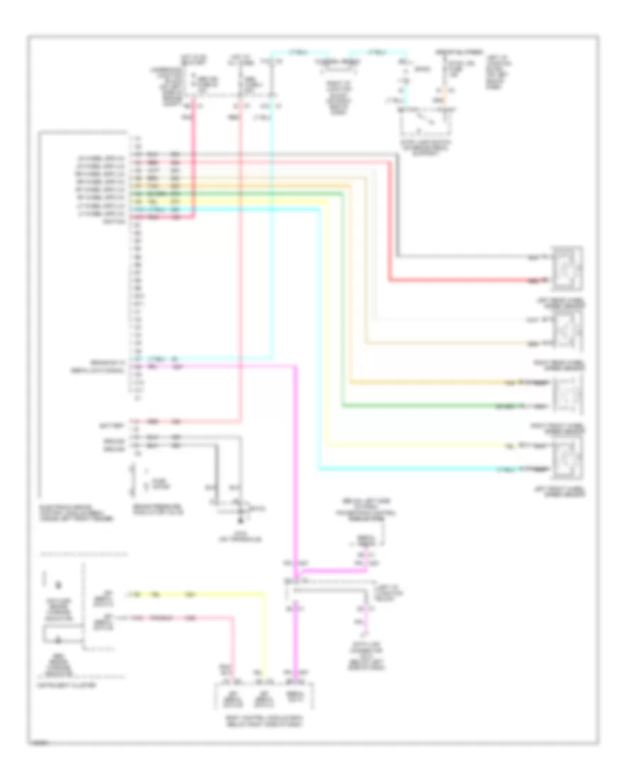
Compressor Wiring Diagram for Chevrolet Malibu 2002
 https://portal-diagnostov.com/license.html
Automotive Electricians Portal FZCO
Automotive Electricians Portal FZCO
https://portal-diagnostov.com/license.html
https://portal-diagnostov.com/license.html
Automotive Electricians Portal FZCO
Automotive Electricians Portal FZCO
List of elements for Compressor Wiring Diagram for Chevrolet Malibu 2002:
- A/c bfc fuse 37 10a
- A/c comp micro- relay
- A/c compressor clutch
- A/c compressor clutch diode
- A/c refrigerant pressure sensor (on front of engine compt)
- A/c req
- A/c request sig
- Body control module (bcm) (below right side of dash)
- Class 2 serial data
- Clutch rly ctrl
- G103 (right rear of engine)
- Hot in run or start
- Hvac control assembly
- Left i/p fuse block (left end of dash)
- Low ref
- Powertrain control module (pcm) (below left side of dash, near steering column)
- Sensor signal
- Splice pack sp103
- Underhood fuse block (left side of engine compt)
- Volt ref
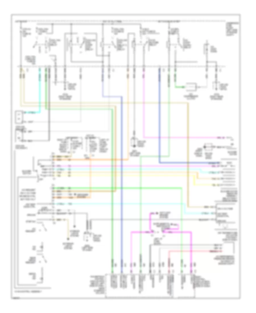
Manual A/C Wiring Diagram for Chevrolet Malibu 2002
List of elements for Manual A/C Wiring Diagram for Chevrolet Malibu 2002:
- 5 volt ref
- A/c bfc fuse 37 10a
- A/c comp diode
- A/c comp micro- relay
- A/c compressor clutch
- A/c refrigerant pressure sensor (on front of engine compt)
- A/c refrigerant pressure sensor signal
- A/c request
- A10
- A11
- Air temp door ctrl
- Air temperature actuator (top right side of dash)
- Anti-lock brakes system
- B11
- B12
- Bat pos volt
- Blower motor
- Blower motor resistor assembly (below right side of dash)
- Blower switch
- Body control module (bcm) (below right side of dash)
- C10
- C12
- Class 2 serial data
- Cool fan 1 fuse 8 30a
- Cool fan 1 mini- relay
- Cool fan 2 fuse 52 15a
- Cool fan 2 ground fuse 55 15a
- Cooling fan relay 2 mini- relay
- Cooling fan (left)
- Cooling fan (right)
- Cooling fan mode mini- relay
- Ctrl clutch relay a/c compressor
- D10
- D11
- Defog on ind
- Defogger system
- Exterior lights system
- F11
- G103 (right rear of engine)
- G201 (left side of dash)
- G202 (left side of dash)
- G203 (right side of dash)
- Ground
- Hi blo mot fuse 53 30a
- High speed cooling fan relay ctrl
- Hot at all times
- Hot in run
- Hot in run or start
- Htr a/c ign fuse 46 10a
- Hvac blower fuse c 20a
- Hvac blower relay
- Hvac control assembly
- Ign 3 voltage
- Illum
- Interior lights system
- Ipc/ hvac batt fuse 10a
- Left i/p fuse block
- Left i/p fuse block (left end of dash)
- Low reference
- Low speed cooling fan relay ctrl
- Off
- On ind
- Powertrain control module (pcm) (below left side of dash, near steering column)
- Rear defog request
- Right i/p fuse block (right end of dash)
- Rr defog ctrl
- Serial data class 2
- Signal a/c request
- Splice pack sp103
- Splice pack sp201
- Splice pack sp202
- Splice pack sp203
- Step dim
- Tan
- Underhood fuse block (left side of engine compt)
ANTI-LOCK BRAKES
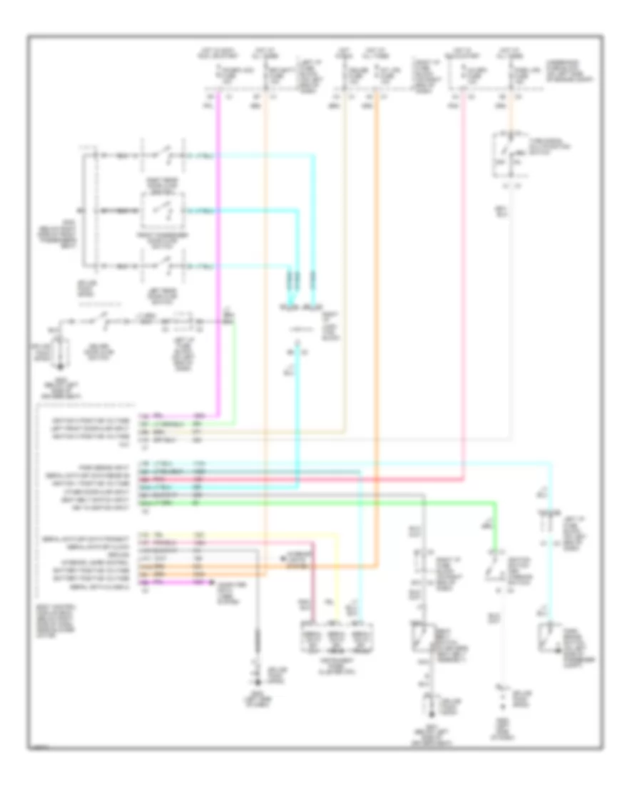
Anti-lock Brake Wiring Diagrams for Chevrolet Malibu 2002
List of elements for Anti-lock Brake Wiring Diagrams for Chevrolet Malibu 2002:
- (below left side of dash) powertrain control module (pcm)
- A10
- A11
- A12
- A3 c3
- A7 c3
- Abs fuse 4 50a
- Abs ign fuse 40 10a
- Antilock brake warning indicator
- B10
- B11
- Battery
- Body control module (bcm) (below right side of dash)
- Brake pressure modulator valve
- Brake sw in
- C10
- C11
- C3 b2
- D2 c1
- Data link connector (dlc) (below left side of dash)
- E3 c1
- Electronic brake control module (ebcm) (inside left front fender)
- F12
- G103 (on transaxle)
- Ground
- Hot at all times
- Hot in on or start
- Ignition
- Instrument cluster
- Left front wheel speed sensor
- Left i/p junction block
- Left i/p junction block (on left end of dash)
- Left rear wheel speed sensor
- Lf wheel spd (hi)
- Lf wheel spd (lo)
- Lr wheel spd (hi)
- Lr wheel spd (lo)
- Nca
- Pnk
- Pump motor
- Red
- Red brake warning indicator
- Rf wheel spd (hi)
- Rf wheel spd (lo)
- Right front wheel speed sensor
- Right i/p junction block (on right end of dash)
- Right rear wheel speed sensor
- Rr wheel spd (hi)
- Rr wheel spd (lo)
- Serial data
- Serial data signal
- Sp103
- Sp303
- Spi serial data a
- Spi serial data b
- Stop lamp switch (on brake pedal support)
- Stop lps fuse 15a
- Tan
- Underhood junction block (on left side of engine compt)
ANTI-THEFT
Anti-theft Wiring Diagram for Chevrolet Malibu 2002
List of elements for Anti-theft Wiring Diagram for Chevrolet Malibu 2002:
- A/c bfc fuse 10a
- A10
- A12
- Body control module (bcm) (below right side of dash, near blower motor)
- Data link connector (below left side of dash)
- Electronic brake control module
- G202 (left side of dash)
- Gnd
- Hot in acc, run or start
- Hot in run or start
- Ign
- Ign (0) voltage
- Ign (1)
- Ignition key
- Instrument panel cluster
- Ipc/bfc acc fuse 10a
- Left i/p fuse block (left side of dash)
- Passlock gnd
- Passlock ref v
- Passlock sensor (left side of dash)
- Passlock sig
- Pnk
- Powertrain control module (below left side of dash, near steering column)
- Remote control door lock receiver (rcdlr) (on rear package shelf)
- Sensing & diag- nostic module
- Serial data a
- Serial data b
- Serial data class 2
- Splice pack sp202
- Srl data class 2
- Theft system indicator
- Underhood junction block (on left side of engine compt)
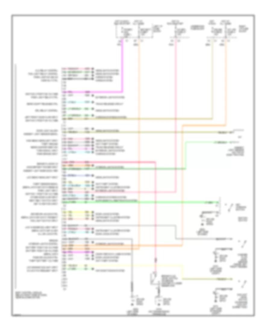
BODY COMPUTER
Body Computer Wiring Diagrams for Chevrolet Malibu 2002
List of elements for Body Computer Wiring Diagrams for Chevrolet Malibu 2002:
- (left side of dash)
- A/c bfc fuse 37 10a
- A/c switch request input
- A10
- A11
- A12
- Air conditioning system
- Alc relay control
- All dr lock ctrl
- Ambient lght snsr sig 5v ref
- Ambient light sensor (on top of dash trim pad)
- Ambient light sensor signal
- Anti-theft system
- B10
- B11
- B12
- Battery positive voltage
- Bfc batt fuse f 10a
- Body control module (below right side of dash, near blower motor)
- Brake fluid level switch (on brake master cylinder reservoir)
- Brake fluid sw in
- Computer data lines system
- Coolant level switch (on engine coolant surge tank)
- Cruise fuse b 10a
- Door lock unlock
- Door locks system
- Driver dr unlock ctrl
- Drl relay control
- Exterior lights system
- Fog light relay control
- Fog light switch input
- G101 (left side of engine compt)
- G103 (on transmission/ transaxle)
- G202
- G202 (left side of dash)
- Ground
- Headlights system
- High beam headlight input
- Horn rly ctrl
- Horns system
- Hot at all times
- Hot in accy, run or start
- Hot in run
- Hot in run or start
- Ignition 0 positive voltage
- Ignition 1 positive voltage
- Ignition 3 positive voltage
- Ignition switch
- Inadvertent power input
- Instrument cluster system
- Int lps fuse a 10a
- Interior lights control
- Interior lights system
- Ipc/bfc acc fuse j 10a
- Key in ignition input
- Key warning switch
- Left front door ajar input
- Left i/p fuse block
- Low beam headlight input
- Low engine coolant input
- Low washer solvent input
- Other door ajar input
- Park brake input
- Park lamp sw sig on
- Park light input
- Park light relay ctrl
- Pass dr unlock ctrl
- Pnk
- Rear compartment sw
- Rear compt release ctrl
- Right i/p fuse block
- Seat belt switch input
- Serial data
- Serial data spi clock
- Serial data spi data receive
- Serial data spi data transmit
- Splice pack sp101
- Splice pack sp103
- Splice pack sp202
- Theft battery voltage
- Theft ground
- Theft sensor signal
- Trunk release circuit
- Turn signal input
- Underhood fuse block
- Warning system
- Warning systems system
- Washer fluid level sensor (inside left front fender)
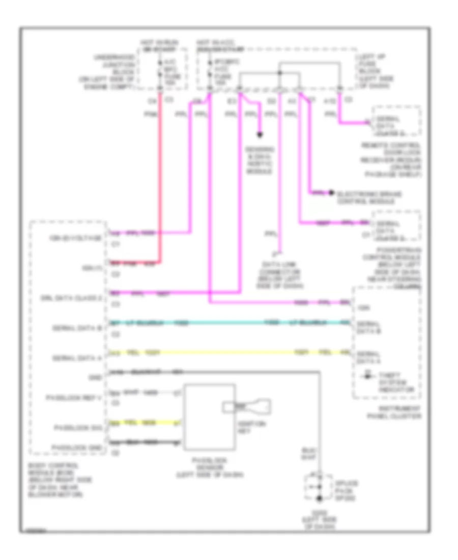
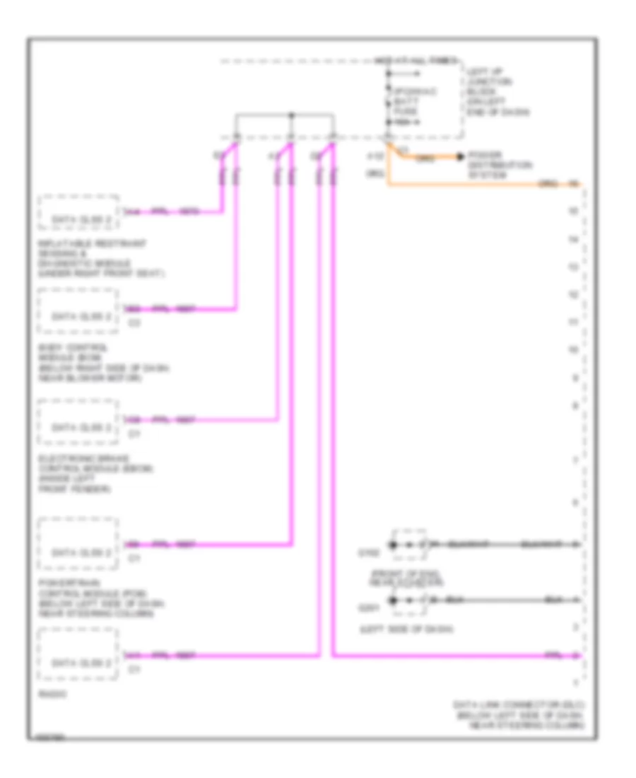
COMPUTER DATA LINES
Computer Data Lines for Chevrolet Malibu 2002
List of elements for Computer Data Lines for Chevrolet Malibu 2002:
- (front of eng, near starter)
- (left side of dash)
- A12
- Body control module (bcm) (below right side of dash, near blower motor)
- Data clss 2
- Data link connector (dlc) (below left side of dash, near steering column)
- Electronic brake control module (ebcm) (inside left front fender)
- G102
- G201
- Hot at all times
- Inflatable restraint sensing & diagnostic module (under right front seat)
- Ipc/hvac batt fuse 10a
- Left i/p junction block (on left end of dash)
- Power distribution system
- Powertrain control module (pcm) (below left side of dash, near steering column)
- Radio
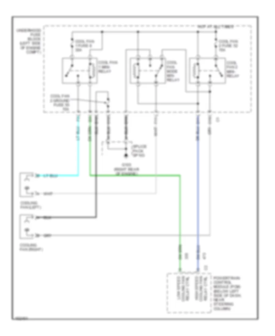
COOLING FAN
Cooling Fan Wiring Diagram for Chevrolet Malibu 2002
List of elements for Cooling Fan Wiring Diagram for Chevrolet Malibu 2002:
- B12
- C10
- C12
- Cool fan 1 fuse 8 30a
- Cool fan 1 mini- relay
- Cool fan 2 fuse 52 15a
- Cool fan 2 ground fuse 55 15a
- Cool fan 2 mini- relay
- Cool fan mode min- relay
- Cooling fan (left)
- Cooling fan (right)
- D10
- D11
- F11
- G103 (right rear of engine)
- High speed cooling fan relay ctrl
- Hot at all times
- Low speed cooling fan relay ctrl
- Powertrain control module (pcm) (below left side of dash, near steering column)
- Splice pack sp103
- Underhood fuse block (left side of engine compt)
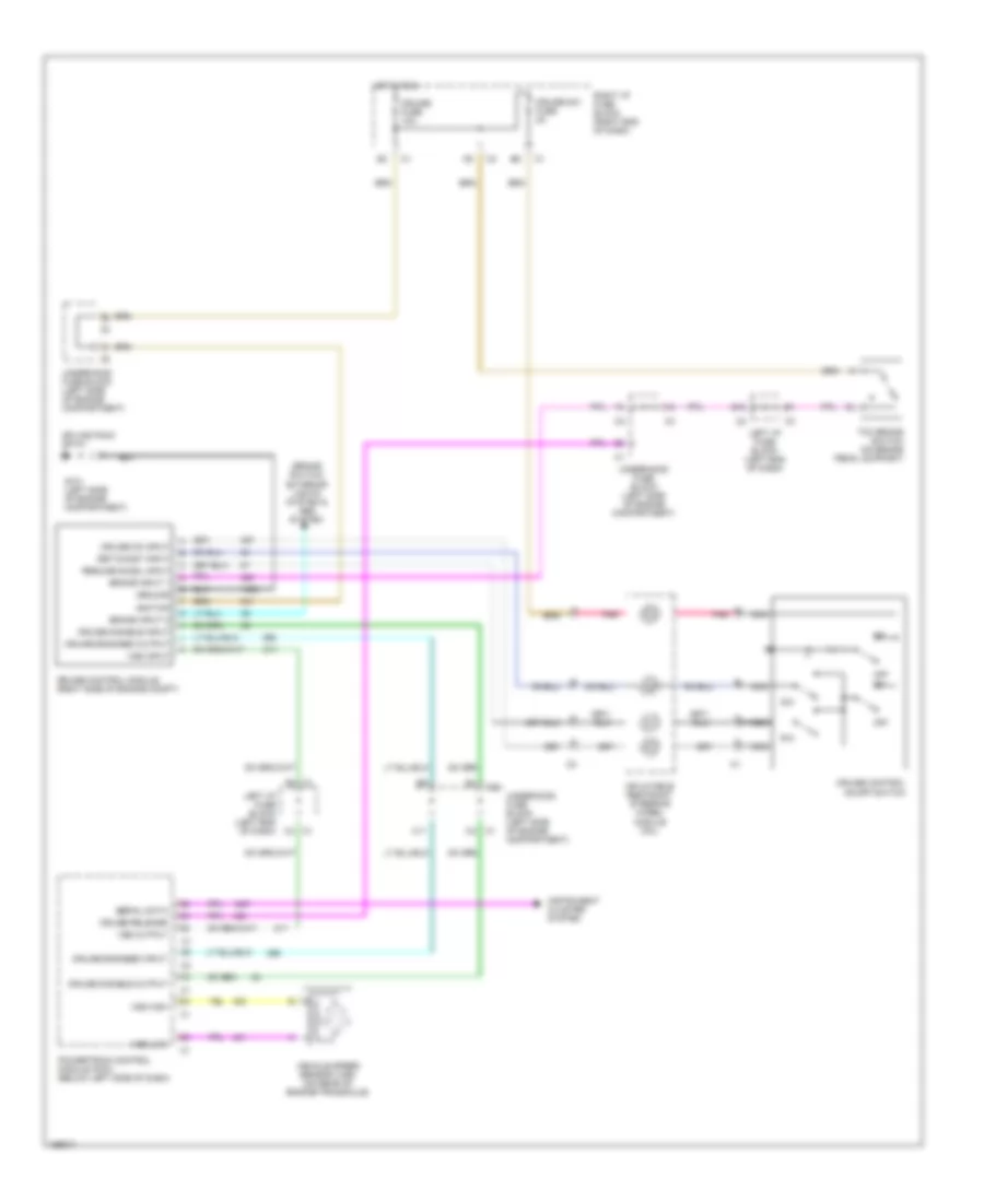
CRUISE CONTROL
Cruise Control Wiring Diagram for Chevrolet Malibu 2002
List of elements for Cruise Control Wiring Diagram for Chevrolet Malibu 2002:
- (brake switch) exterior lights system & abs system
- B12
- Brake input 1
- Brake input 2
- C1 c3
- C11
- C4 c1
- Cruise control module (right side of engine compt)
- Cruise control on/off switch
- Cruise disable input
- Cruise disable output
- Cruise engaged input
- Cruise engaged output
- Cruise fuse 10a
- Cruise on input
- Cruise release
- Cruise sw fuse 2a
- F6 c1
- G101 (left side of engine compartment)
- Ground
- Hot in run
- Ignition
- Inflatable restraint steering wheel module coil
- Instrument cluster system
- Left i/p fuse block (left end of dash)
- Nca
- Off
- Pnk
- Powertrain control module (pcm) (below left side of dash)
- R/a
- Resume/accel input
- Right i/p fuse block (right end of dash)
- S/c
- Serial data
- Set/coast input
- Splice pack sp101
- Tcc brake switch (on brake pedal support)
- Underhood fuse block (left side of engine compartment)
- Vehicle speed sensor (vss) (on rear of engine/transaxle)
- Vss high
- Vss input
- Vss low
- Vss output
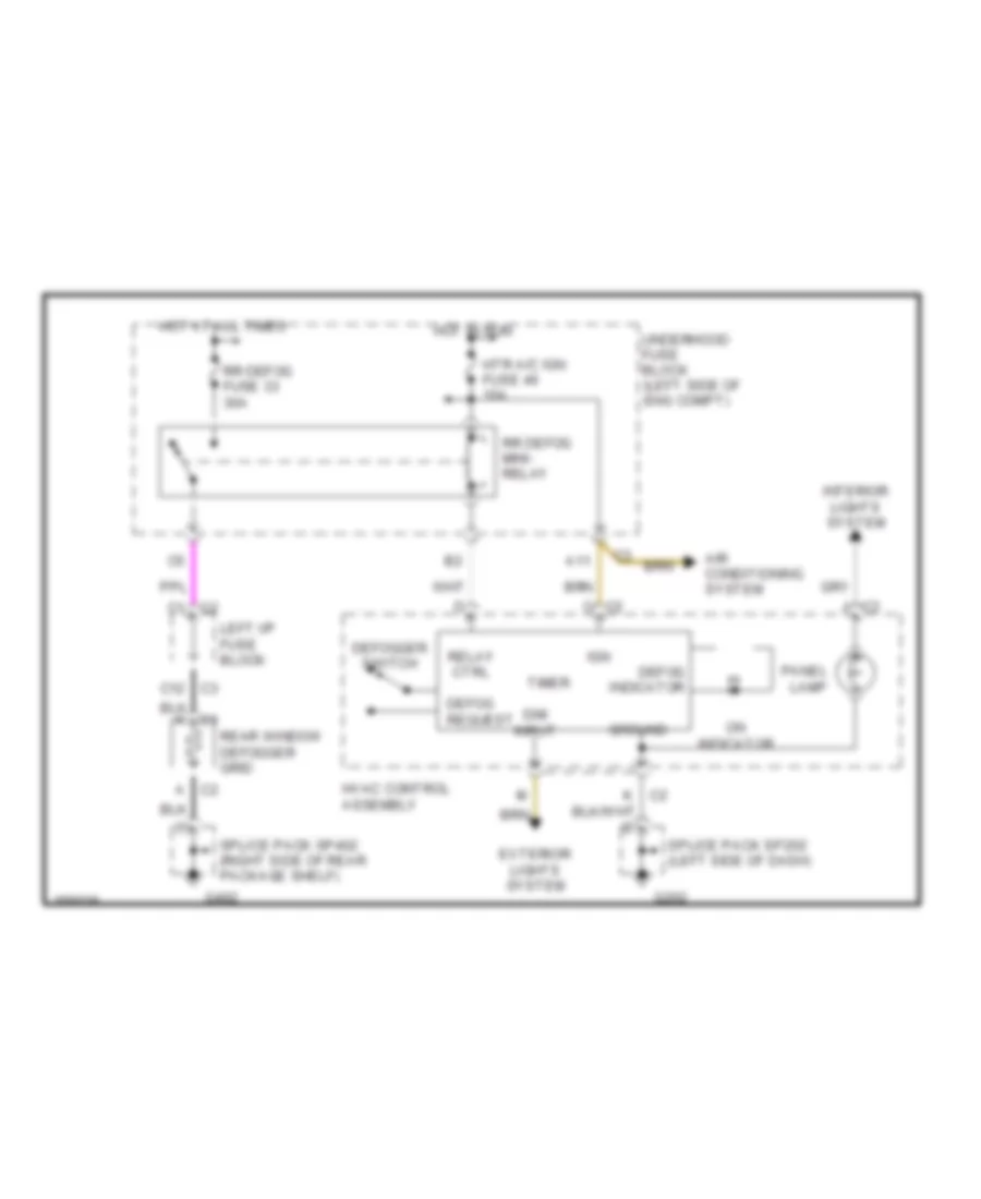
DEFOGGERS
Defogger Wiring Diagram for Chevrolet Malibu 2002
List of elements for Defogger Wiring Diagram for Chevrolet Malibu 2002:
- A c2
- A11
- Air conditioning system
- C c2
- C1 c2
- C2 j
- C3 c12
- Defog indicator
- Defog request
- Defogger switch
- Dim input
- Exterior lights system
- G202
- G402
- Ground
- Hot at all times
- Hot in run
- Htr a/c ign fuse 46 10a
- Hvac control assembly
- Ign
- Interior lights system
- K c2
- Left i/p fuse block
- On indicator
- Panel lamp
- Rear window defogger grid
- Relay ctrl
- Rr defog fuse 33 30a
- Rr defog mini- relay
- Splice pack sp202 (left side of dash)
- Splice pack sp402 (right side of rear package shelf)
- Timer
- Underhood fuse block (left side of eng compt)
ENGINE PERFORMANCE
3.1L
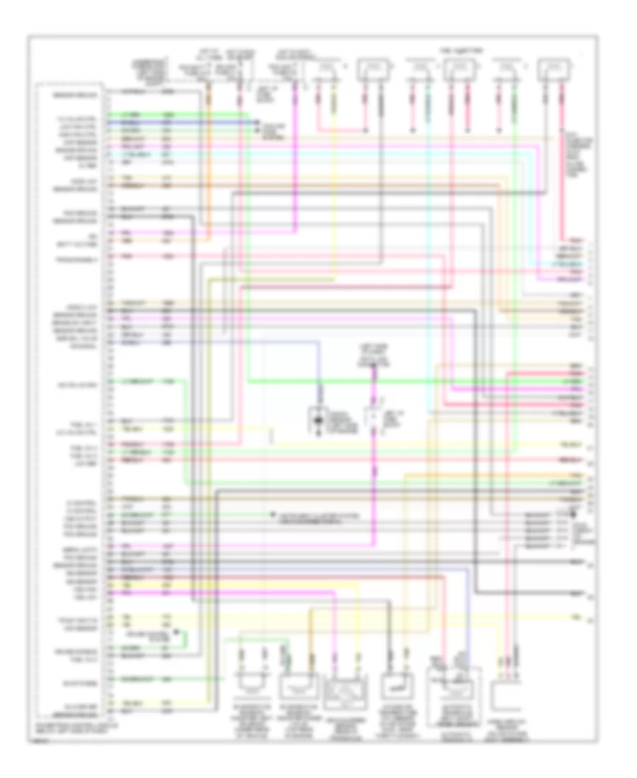
3.1L VIN J, Engine Performance Wiring Diagrams (1 of 3) for Chevrolet Malibu 2002
List of elements for 3.1L VIN J, Engine Performance Wiring Diagrams (1 of 3) for Chevrolet Malibu 2002:
- (left side of dash)
- 1-2 valve ctrl
- 2-3 valve ctrl
- 5v ref
- Automatic transaxle
- Automatic transaxle input shaft speed sensor
- Batt voltage
- Brake sw input
- Ckp sensor
- Cmp sensor
- Cooling fans system
- Cruise control system
- Cruise disable
- Data link connector
- Egr sol valve
- Engine spd sig
- Evap purge
- Evaporative emission canister purge valve (top rear of engine)
- Evaporative emission canister vent solenoid (under rear of vehicle)
- Fuel inj 1
- Fuel inj 2
- Fuel inj 3
- Fuel inj 5
- Fuel injectors
- G102 (front of engine)
- High fan ctrl
- Ho2s 2 low
- Ho2s low
- Hot at all times
- Hot in accy, run or start
- Hot in run or start
- Iac coil b high
- Ic control
- Ign
- Ign mod fuse 41 10a
- Inj 6 driver
- Instrument cluster system (vehicle speed signal)
- Intake air temperature (iat) sensor (in air intake duct, near throttle body)
- Iss sensor
- Knock sensor (left side of engine)
- Ks signal
- Left i/p fuse block
- Low fan ctrl
- Low ref
- Maf sensor
- Mass airflow sensor (on air intake duct assembly)
- Pcm acc fuse g 10a
- Pcm batt fuse 44 10a
- Pcm ground
- Pnk
- Powertrain control module (below left side of dash)
- S101 (injector harness, 16 cm from in-line connec- tor)
- Sensor ground
- Serial data
- Tan
- Tr sw input b
- Trans range a
- Underhood fuse block (left side of engine compt)
- Vehicle speed sensor (rear of transaxle)
- Vss high
- Vss low
- Vss output
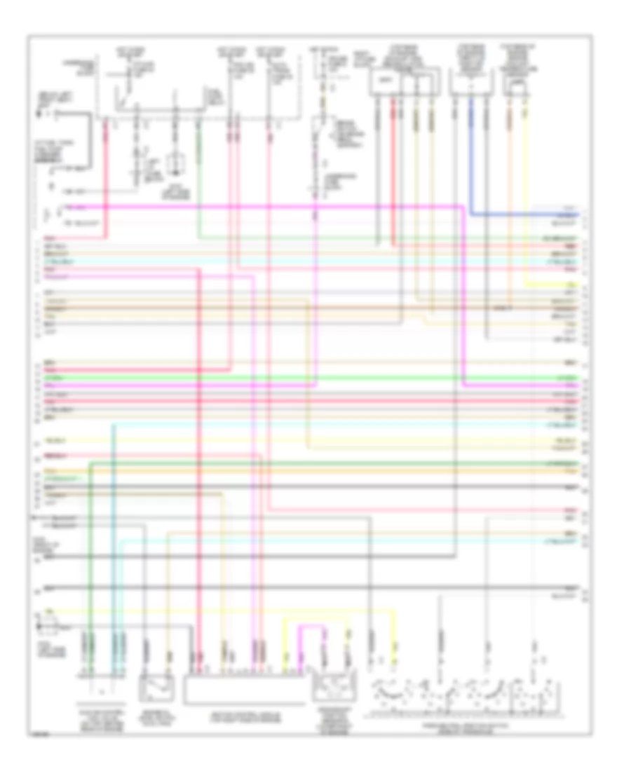
3.1L VIN J, Engine Performance Wiring Diagrams (2 of 3) for Chevrolet Malibu 2002
List of elements for 3.1L VIN J, Engine Performance Wiring Diagrams (2 of 3) for Chevrolet Malibu 2002:
- (at fuel tank)
- (below left front seat) g301
- (top rear of engine) engine coolant temperature sensor
- (top rear of engine) exhaust gas recirculation valve
- (top rear of engine) throttle position sensor
- Auto trans fuse 38 10a
- B12
- Brake switch (on brake pedal support)
- Crankshaft position sensor b (lower right of engine)
- Cruise fuse d 10a
- Engine oil level switch (in oil pan)
- F/p injr fuse 48 15a
- Fuel pump & sender assembly
- Fuel pump relay
- G102 (front of engine)
- G103 (left side of engine)
- Hot in run
- Hot in run or start
- Idle air control (iac) valve (on top center rear of engine)
- Ignition control module (top right side of engine)
- Left i/p fuse block
- Nca
- Park/neutral position switch (side of transaxle)
- Pcm ign fuse 39 10a
- Pnk
- Red
- Right i/p fuse block
- S102
- Tan
- Underhood fuse block
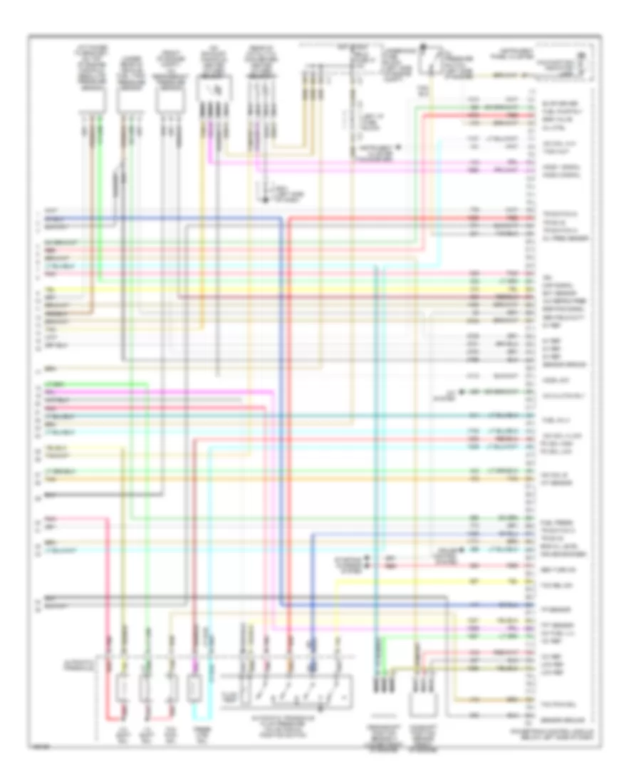
3.1L VIN J, Engine Performance Wiring Diagrams (3 of 3) for Chevrolet Malibu 2002
List of elements for 3.1L VIN J, Engine Performance Wiring Diagrams (3 of 3) for Chevrolet Malibu 2002:
- (attached to bracket, on top of engine) manifold absolute pressure sensor
- (front of engine) compt) a/c refrigerant pressure sensor
- (on exhaust manifold) heated oxygen sensor 1
- (rear of catalytic converter) heated oxygen sensor 2
- (under rear of vehicle) fuel tank pressure sensor
- +5v fuel lvl
- 1-2 shift sol
- 12v ref
- 2-3 shift sol
- 5v ref
- A tan
- A/c clutch rly
- A/c refrig pres
- A/c system
- Automatic transaxle
- Automatic transaxle fluid pressure valve manual position switch
- B11
- C11
- Camshaft position sensor (front of engine)
- Crankshaft position sensor a (lower front of engine)
- Cruise control system
- Cruise engaged
- Ect sensor
- Egr pos signal
- Egr valve
- Eng oil level
- Erls fuse 47 10a
- Evap driver
- Fluid temp
- Fuel inj 4
- Fuel press
- Fuel pump rly
- G201 (left side of dash)
- Gen field duty
- Gen turn on
- Ho2s 1 signal
- Ho2s 2 signal
- Ho2s low
- Hot in run
- Iac coil a hi
- Iac coil a low
- Iac coil b
- Iat sensor
- Ign
- Instrument cluster (tachometer)
- Instrument panel cluster
- Left i/p fuse block
- Low ref
- Malfunction indicator lamp
- Map signal
- Mil ctrl
- Nca
- Oil pressure switch (left side of engine)
- Oil pres sensor
- Pc sol high
- Pc sol low
- Pnk
- Pnk e
- Pnk n
- Powertrain control module (below left side of dash)
- Press ctrl sol
- Red
- Red p
- Sensor ground
- Starting/ charging system
- Tach out
- Tan
- Tcc pwm sol
- Tcc rel sw
- Tft sensor
- Tp sensor
- Tr sw b
- Tr switch a
- Tr switch c
- Tr switch d
- Underhood fuse block (left side of engine compt)
EXTERIOR LIGHTS
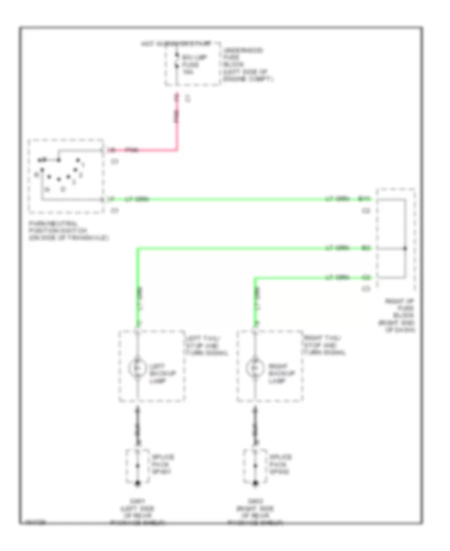
Back-up Lamps Wiring Diagram for Chevrolet Malibu 2002
List of elements for Back-up Lamps Wiring Diagram for Chevrolet Malibu 2002:
- B/u lmp fuse 10a
- B11
- G401 (left side of rear package shelf)
- G402 (right side of rear package shelf)
- Hot in run or start
- Left backup lamp
- Left tail/ stop and turn signal
- Park/neutral position switch (on side of transaxle)
- Pnk
- Right backup lamp
- Right i/p fuse block (right end of dash)
- Right tail/ stop and turn signal
- Splice pack sp401
- Splice pack sp402
- Underhood fuse block (left side of engine compt)
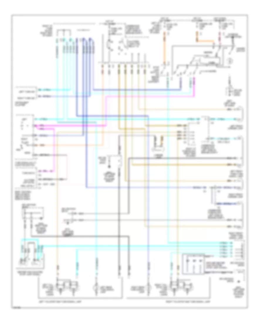
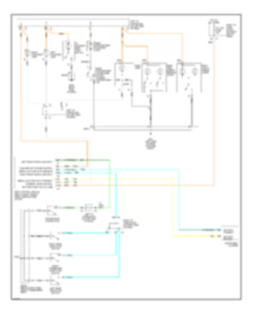
Exterior Lamps Wiring Diagram for Chevrolet Malibu 2002
List of elements for Exterior Lamps Wiring Diagram for Chevrolet Malibu 2002:
- A10
- A11
- Alc park lamp ctrl relay 19
- Alc park lmp cntrl
- B10
- B11
- Body control module (bcm) (below right side of dash)
- C10
- C12
- Center high mounted stop lamp (chmsl)
- G101 (left side of engine compt)
- G201 (left side of dash)
- G401 (left side of rear package shelf)
- G402 (right side of rear package shelf)
- Hazard
- Hazard lps fuse 10a
- Hazard switch
- Head
- Hot at all times
- Hot in run or start
- Instrument cluster
- Interior lights system
- Left
- Left front marker lamp
- Left front park/turn signal lamp
- Left i/p fuse block (left end of dash)
- Left rear turn signal lamp
- Left tail/ stop and turn signal lamps
- Left tail/stop and turn signal lamp
- Left turn ind
- License lamp
- Nca
- Off
- Park lps fuse 15a
- Pnk
- Prk
- Prk lmp rly
- Right
- Right front marker lamp
- Right front park/turn signal lamp
- Right i/p fuse block (right end of dash)
- Right rear turn signal lamp
- Right tail/ a
- Right tail/stop and turn signal lamp
- Right turn ind
- Splice pack sp101
- Splice pack sp201
- Splice pack sp303
- Splice pack sp401
- Splice pack sp402
- Spoiler center high mounted stop lamp (chmsl)
- Stop and turn signal lamps
- Stop lamp switch (on brake pedal support)
- Stop lps fuse 15a
- Timer
- Turn lps fuse 10a
- Turn sig in
- Turn signal/multi- function switch
- Underhood fuse block (left side of engine compt)
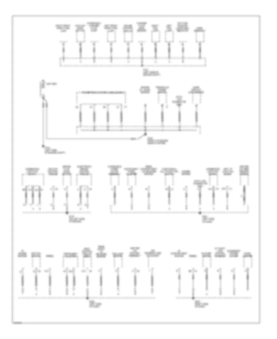
GROUND DISTRIBUTION
Ground Distribution Wiring Diagram (1 of 2) for Chevrolet Malibu 2002
List of elements for Ground Distribution Wiring Diagram (1 of 2) for Chevrolet Malibu 2002:
- A/t shift lock control solenoid
- A10
- A12
- Accessory power outlet
- Air temperature actuator
- B10
- Battery
- Blower motor
- Body control module (bcm)
- Brake fluid level switch
- C1 d10
- C12
- Cigar lighter
- Coolant level switch
- Cruise control module
- Data link connector (dlc)
- Daytime running lamps (drl) resistor
- E10
- Electronic brake control module
- Engine oil level switch
- Fog lamp switch
- G101 (left side of engine compt)
- G102 (front of engine near starter)
- G103 (on left side of engine)
- G104 (left side of engine compt)
- G201 (left side of dash)
- G202 (left side of dash)
- G203 (right side of dash)
- Hazard switch
- Heated oxygen sensor (ho2s 2)
- Heater a/c control assembly
- Horn assembly
- I/p compartment switch
- I/p dimmer switch
- Ignition control module
- Ignition switch
- Instrument cluster
- Instrument panel cluster
- Left fog lamp
- Left front park/turn lamp
- Left i/p junction block
- Mass airflow (maf) sensor
- Nca
- Powertrain control module (pcm)
- Radio
- Rear compartment lid release switch
- Rear compt lid release switch
- Right fog lamp
- Right front park/turn lamp
- Transaxle range switch
- Turn signal/ multifunction switch
- Underhood junction block
- Washer fluid level sensor
- Windshield washer fluid pump
- Windshield wiper motor assembly
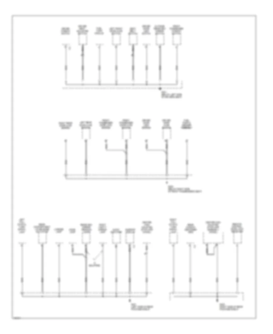
Ground Distribution Wiring Diagram (2 of 2) for Chevrolet Malibu 2002
List of elements for Ground Distribution Wiring Diagram (2 of 2) for Chevrolet Malibu 2002:
- Audio amplifier
- Center high mounted stoplamp (chmsl)
- Center high mounted stoplamp assembly (chmsl)
- Dome lamp
- Driver door ajar switch
- Driver door lock switch
- Driver seat adjuster switch
- Driver window switch
- Front passenger door ajar switch
- Front passenger door lock switch
- Front passenger window switch
- Fuel pump & sender assembly
- Fuel tank module
- G301 (below left side of driver's seat)
- G302 (below right side of front passenger's seat)
- G401 (left side of rear package shelf)
- G402 (right side of rear package shelf)
- If equipped
- Left front door ajar switch
- Left rear door ajar switch
- Left tail/ stop & turn signal lamp
- License lamp
- Nca
- Outside rearview mirror switch
- Rear compartment lid release actuator
- Rear window defogger grid
- Rearview mirror reading lamps
- Remote control door lock receiver
- Right rear door ajar switch
- Right tail/ stop & turn signal lamp
- Right vanity mirror lamp
- Seat belt switch
- Sunroof module
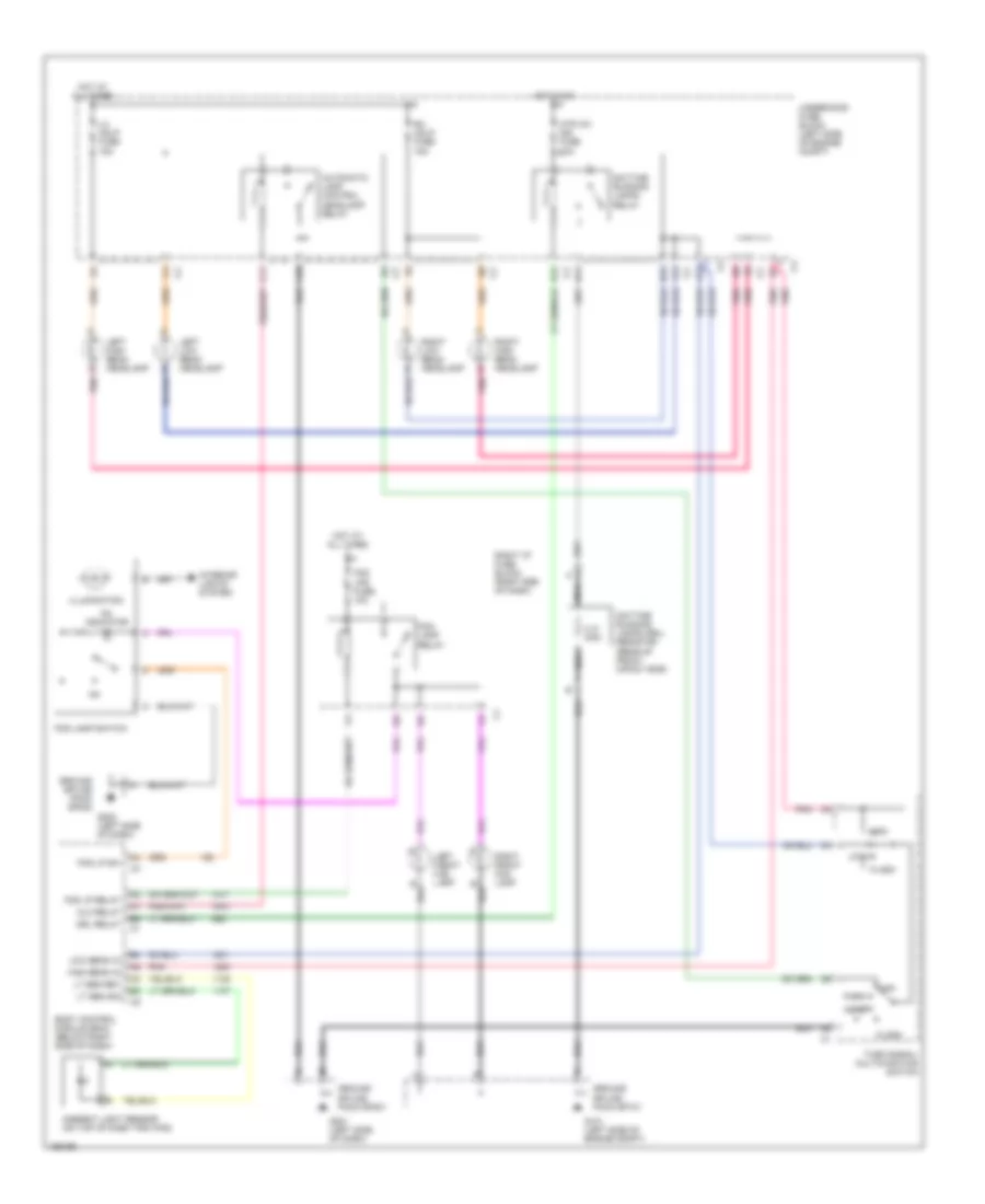
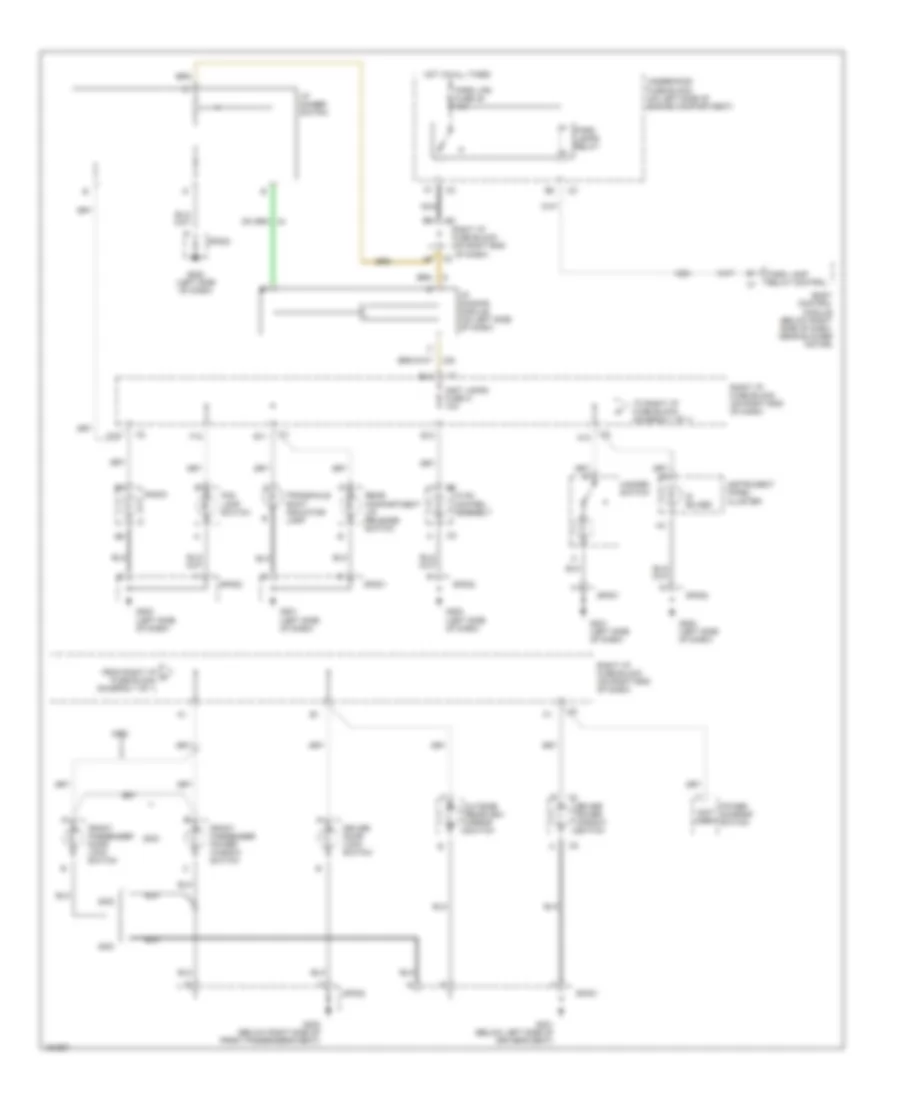
HEADLIGHTS
Headlight Wiring Diagram for Chevrolet Malibu 2002
List of elements for Headlight Wiring Diagram for Chevrolet Malibu 2002:
- 0.31 ohm
- A10
- A12
- Alc relay
- Ambient light sensor (on top of dash trim pad)
- Automatic lamp control headlamp relay
- B12 c3
- B3 c3
- Body control module (bcm) (below right side of dash)
- C11
- C4 c2
- D11
- Daytime running lamps (drl) resistor (rear of front impact bar)
- Daytime running lamps relay
- Drl relay
- E12
- E8 c2
- F12 c2
- F4 c1
- F6 c2
- Flash
- Fog lamp relay
- Fog lamp switch
- Fog lp relay
- Fog lp sw
- Fog lps fuse 10a
- G101 (left side of engine compt)
- G201 (left side of dash)
- G202 (left side of dash)
- Ground splice pack sp101
- Ground splice pack sp201
- Ground splice pack sp202
- Head
- High
- High beam in
- Hot at all times
- Hot in on
- Htr a/c ign fuse 10a
- Illumination
- Interior lights system
- Left front fog lamp
- Left high beam headlamp
- Left low beam headlamp
- Lh hdlp fuse 15a
- Low
- Low beam in
- Lt sen ret
- Lt sen sig
- Nca
- Off
- On indicator
- Park
- Pnk
- Rh hdlp fuse 15a
- Right front fog lamp
- Right high beam headlamp
- Right i/p fuse block (right end of dash)
- Right low beam headlamp
- Turn signal/ multifunction switch
- Underhood fuse block (left side of engine compt)
HORN
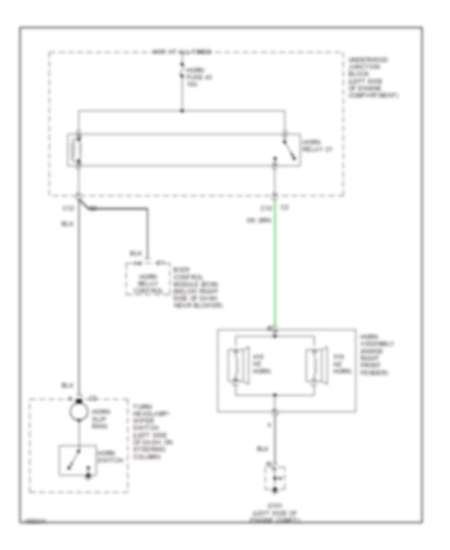
Horn Wiring Diagram for Chevrolet Malibu 2002
List of elements for Horn Wiring Diagram for Chevrolet Malibu 2002:
- Body control module (bcm) (below right side of dash near blower)
- C12
- G101 (left side of engine compt)
- Horn assembly (inside right front fender)
- Horn fuse 43 15a
- Horn relay 21
- Horn relay control
- Horn slip ring
- Horn switch
- Hot at all times
- Hz horn
- Turn/ headlamp/ wiper switch (left side of dash, on steering column)
- Underhood junction block (left side of engine compartment)
INSTRUMENT CLUSTER
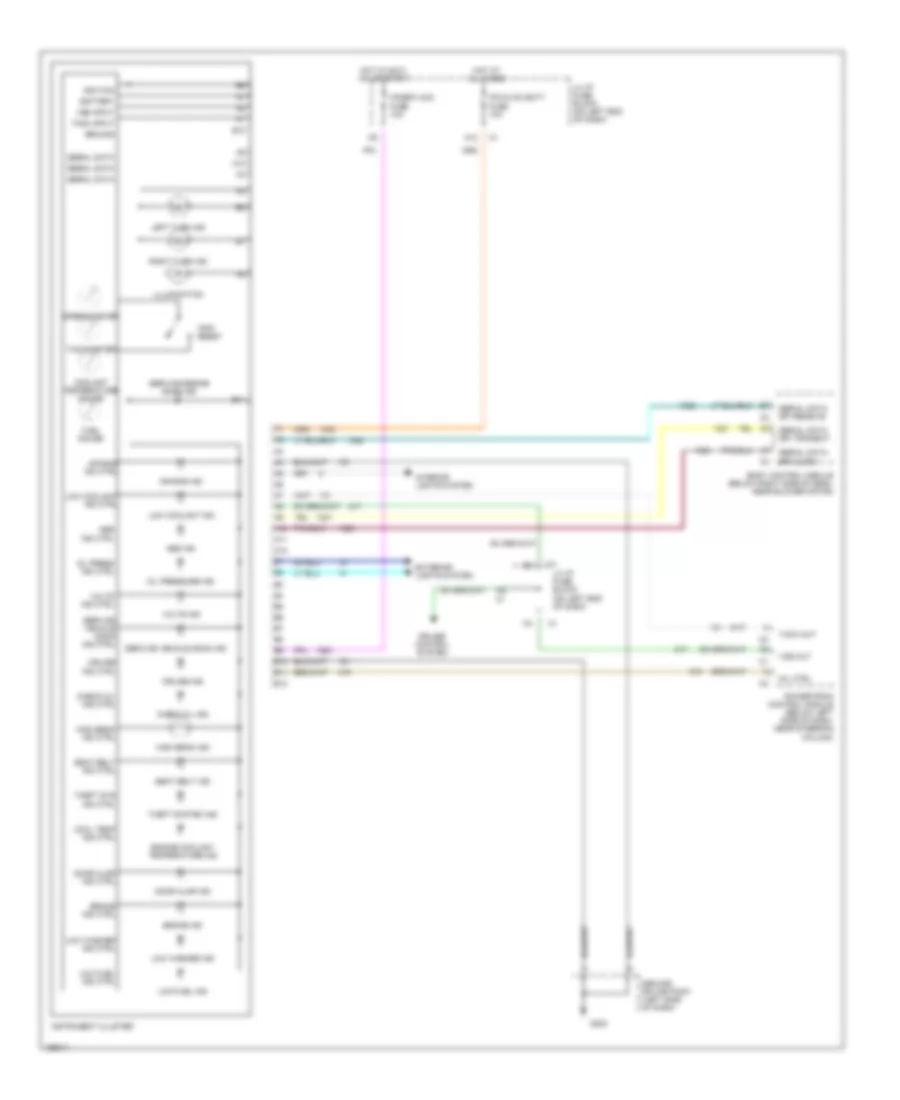
Instrument Cluster Wiring Diagram for Chevrolet Malibu 2002
List of elements for Instrument Cluster Wiring Diagram for Chevrolet Malibu 2002:
- service vehicle soon ind
- A10
- A11
- A12
- Abs ind
- Abs ind ctrl
- Air bag ind
- Air bag ind ctrl
- B10
- B11
- B12
- Battery
- Body control module (below right side of dash, near blower motor)
- Brake ind
- Brake ind ctrl
- Check oil ind
- Check oil ind ctrl
- Cool temp ind ctrl
- Coolant temperature gauge
- Cruise control system
- Cruise ind
- Cruise ind ctrl
- Door ajar ind
- Door ajar ind ctrl
- Engine coolant temperature ind
- Exterior lights system
- Fuel gauge
- G202
- Ground
- Ground splice pack (left side of dash)
- High beam ind
- High beam ind ctrl
- Hot at all times
- Hot in accy, on or start
- Ignition
- Illumination
- Instrument cluster
- Interior lights system
- Ipc/bfc acc fuse 10a
- Ipc/hvac batt fuse 10a
- Left turn ind
- Lh i/p fuse block (on left end of dash)
- Low coolant ind
- Low coolant ind ctrl
- Low fuel ind
- Low fuel ind ctrl
- Low washer ind
- Low washer ind ctrl
- Mil ctrl
- Oil press ind ctrl
- Oil pressure ind
- Powertrain control module (below left side of dash, near steering column)
- Right turn ind
- Seat belt ind
- Seat belt ind ctrl
- Serial data
- Serial data spi clock
- Serial data spi receive
- Serial data spi transmit
- Service engine soon ind
- Service vehicle soon ind ctrl
- Speedometer
- Tach input
- Tach out
- Tachometer
- Theft sys ind ctrl
- Theft system ind
- Trip reset
- Volts ind
- Volts ind ctrl
- Vss input
- Vss out
INTERIOR LIGHTS
Courtesy Lamps Wiring Diagram for Chevrolet Malibu 2002
List of elements for Courtesy Lamps Wiring Diagram for Chevrolet Malibu 2002:
- A11
- A12
- B10
- Battery positive voltage
- Body control module (below right side of dash, near blower motor)
- C10
- Dome lamp
- Door
- Driver door ajar switch
- Front passenger door ajar switch
- G203 (right side of dash)
- G302
- G401 (left side of rear package shelf)
- Hot at all times
- I/p compart- ment lamp switch
- Inadvertant power control
- Instrument cluster
- Int lps fuse 10a
- Interior lamps control
- Left courtesy lamp
- Left front door ajar input
- Left i/p fuse block (on left end of dash)
- Left rear door ajar switch
- Off
- Rear compartment courtesy lamp
- Rear compartment lid release motor (in rear compartment lid)
- Rear view mirror reading lamps
- Right courtesy lamp
- Right front door ajar input
- Right i/p fuse block (on right end of dash)
- Right rear door ajar switch
- Right vanity mirror lamps
- Serial data spi data recieve
- Serial data spi data transmit
- Sp203
- Sp302 (below right side front passenger's seat)
- Sp401
- Spi data recieve
- Spi data transmit
Instrument Illumination Wiring Diagram for Chevrolet Malibu 2002
List of elements for Instrument Illumination Wiring Diagram for Chevrolet Malibu 2002:
- (5 bulbs)
- (not used)
- A12
- B12
- Body control module (below right side of dash, near blower motor)
- C12
- Driver door lock switch
- Driver power window switch
- E11
- E12
- F12
- Fog lamp switch
- From right i/p a fuse block (diagram 1 of 1)
- Front passenger door lock switch
- Front passenger power window switch
- G201 (left side of dash)
- G202 (left side of dash)
- G301 (below left side of driver's seat)
- G302 (below right side of front passenger's seat)
- Hazard switch
- Hot at all times
- Hvac control assembly
- I/p dimmer switch
- I/p dimming module (on left side of dash)
- Inst lamps fuse a 10a
- Instrument panel cluster
- Nca
- Outside rearview mirror switch
- Park lamp relay control
- Park lamps relay
- Park lps fuse 45 15a
- Power sunroof switch
- Radio
- Rear compartment lid release switch
- Right i/p fuse block (on right end of dash)
- Sp201
- Sp202
- Sp301
- Sp302
- To right i/p fuse block (diagram 1 of 1)
- Transaxle shift indicator lamp
- Underhood fuse block (on left side of engine compartment)
POWER DISTRIBUTION
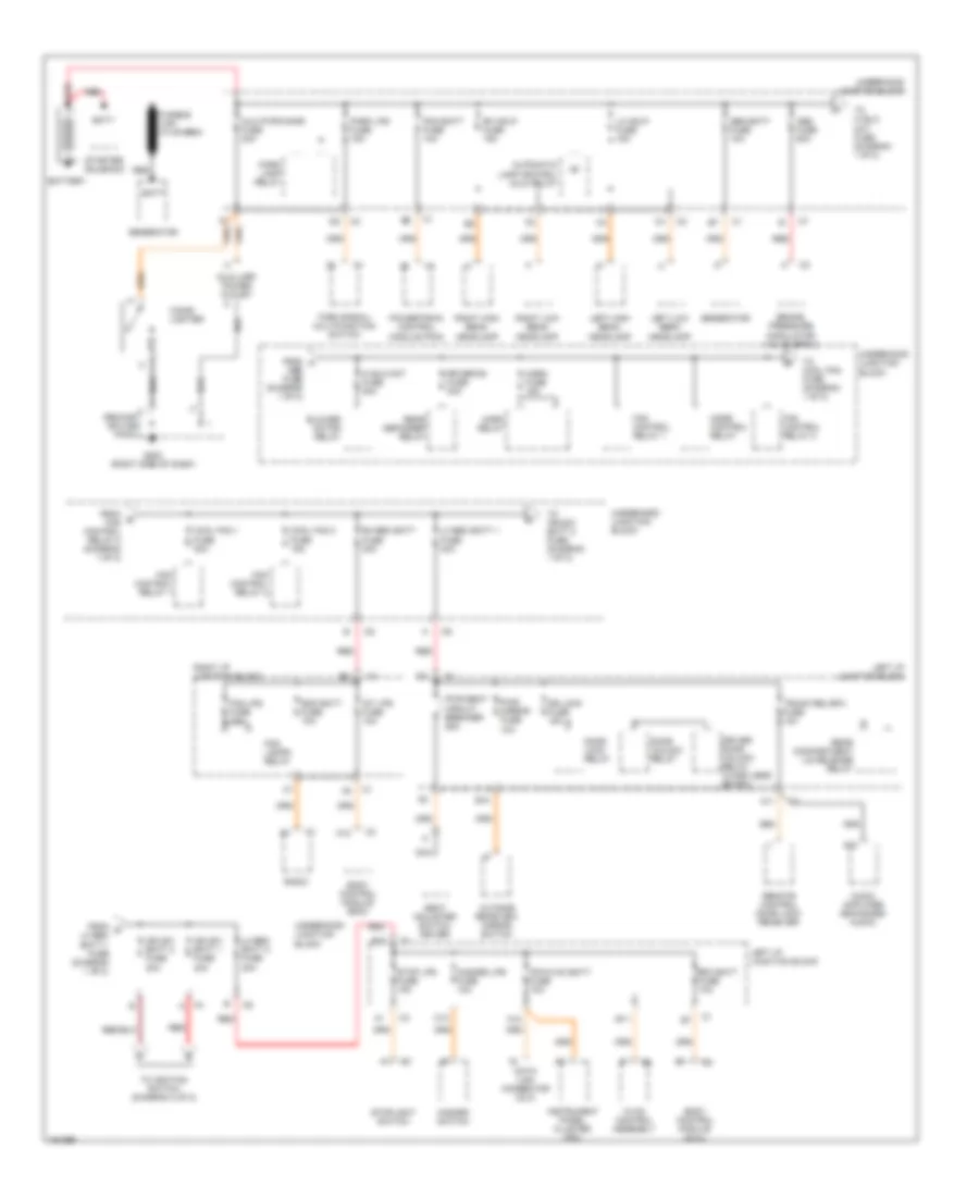
Power Distribution Wiring Diagram (1 of 2) for Chevrolet Malibu 2002
List of elements for Power Distribution Wiring Diagram (1 of 2) for Chevrolet Malibu 2002:
- A11
- A12
- Abs fuse 50a
- Audio amplifier (enhanced audio)
- Automatic lamp control (alc) relay
- Aux pwr/cigar fuse 20a
- Auxiliary power outlet
- B10
- B11
- Batt
- Battery
- Bfc batt fuse 10a
- Blower motor relay
- Body control module (bcm)
- Brake pressure modulator valve (bpmv)
- C12
- Cigar lighter
- Cool fan 1 fuse 30a
- Cool fan 2 fuse 15a
- Data link connector (dlc)
- Door lock relay
- Door unlock relay
- Dr lock fuse 15a
- Driver door unlock relay (w/keyless entry)
- E12
- Fan control relay 1
- Fan control relay 2
- Fog lamps relay
- Fog lps fuse 10a
- From a abs fuse (diagram 1 of 2)
- From b fan control relay 2 (diagram 1 of 2)
- From c lh bec batt 1 fuse (diagram 1 of 2)
- G203 (right side of dash)
- Gen batt fuse 10a
- Generator
- Hazard lps fuse 10a
- Hazard switch
- Hi blo mot fuse 30a
- Horn fuse 15a
- Horn relay
- Hvac control assembly
- Ign sw batt 1 fuse 40a
- Ign sw batt 2 fuse 30a
- Instrument panel cluster (ipc)
- Int lps fuse 10a
- Ipc/hvac batt fuse 10a
- L ground splice pack
- Left high beam headlamp
- Left i/p junction block
- Left low beam headlamp
- Lh bec batt 1 fuse 40a
- Lh bec batt 2 fuse 30a
- Lh hdlp fuse 15a
- Mode control relay
- Nca
- Outside rearview mirror switch
- Park lamp relay
- Park lps fuse 15a
- Pcm batt fuse 10a
- Powertrain control module (pcm)
- Pwr mirror fuse 10a
- Pwr seat circuit breaker 25a
- Radio
- Rdo batt fuse 10a
- Rear compartment lid release relay
- Rear defogger relay
- Red
- Remote control door lock receiver
- Rh bec batt fuse 30a
- Rh hdlp fuse 15a
- Right high beam headlamp
- Right i/p junction block
- Right low beam headlamp
- Rr defog fuse 30a
- Seat adjuster switch driver
- Starter solenoid
- Stop lps fuse 15a
- Stoplight switch
- To cool fan fuse (diagram 1 of 2)
- To hi blo mot fuse (diagram 1 of 2)
- To ign-sw batt 2 fuse (diagram 1 of 2)
- To ignition switch (diagram 2 of 2)
- Trunk rel/rfa fuse 10a
- Turn signal/ multifunction switch
- Underhood junction block
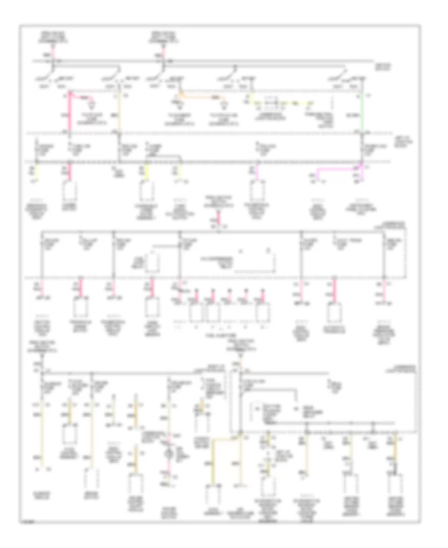
Power Distribution Wiring Diagram (2 of 2) for Chevrolet Malibu 2002
List of elements for Power Distribution Wiring Diagram (2 of 2) for Chevrolet Malibu 2002:
- (not used)
- A/c bfc fuse 10a
- A/c compressor clutch relay
- A11
- A12
- Abs ign fuse 10a
- Accy
- Air bag fuse 10a
- Air temperature actuator
- Auto trans fuse 10a
- Automatic transaxle
- B/u lmp fuse 10a
- Body control module (bcm)
- Brake pressure modulator valve (bpmv)
- Brake switch
- C11
- C201
- Cruise control on/off module
- Cruise control switch
- Cruise fuse 10a
- Cruise sw fuse 2a
- Daytime running lamps (drl) relay
- E11
- Erls fuse 10a
- Evaporative emission (evap) canister purge valve
- Evaporative emission (evap) canister vent solenoid
- F/p injr fuse 15a
- F11
- From ign sw batt 1 fuse (diagram 1 of 2)
- From ign sw batt 2 fuse (diagram 1 of 2)
- From ignition switch (diagram 2 of 2)
- Fuel injectors
- Fuel pump relay
- Hazard switch
- Heated oxygen sensor (ho2s) sensor 1
- Heated oxygen sensor (ho2s) sensor 2
- Htr a/c ign fuse 10a
- Hvac blower fuse 20a
- Hvac assembly
- Hvac control assembly
- Ign mod fuse 10a
- Ignition control module (icm)
- Ignition switch
- Instrument panel cluster (ipc)
- Ipc/bfc acc fuse 10a
- Left i/p junction block
- Lock
- Mass airflow (maf) sensor
- Nca
- Park/neutral position (pnp) switch
- Pcm acc fuse 10a
- Pcm ign fuse 10a
- Pnk
- Powertrain control module (pcm)
- Pwr wndws circuit breaker 25a
- Rdo acc fuse 10a
- Rear defogger relay
- Red
- Right i/p junction block
- Run
- S100
- Sensing & diagnostic module (sdm)
- Sir coil assem- bly
- Start
- Sunroof fuse 20a
- Sunroof module
- To f/p injr fuse (diagram 2 of 2)
- To htr a/c ign fuse (diagram 2 of 2)
- To sunroof fuse (diagram 2 of 2)
- Transaxle range switch
- Turn lps fuse 10a
- Turn/ signal multifunction switch
- Underhood junction block
- Window switch- driver
- Windshield wiper motor assembly
- Wiper fuse 25a
POWER DOOR LOCKS
Power Door Lock Wiring Diagram for Chevrolet Malibu 2002
List of elements for Power Door Lock Wiring Diagram for Chevrolet Malibu 2002:
- A11
- Body control module (right side of dash, near blower motor)
- C10
- Door lock ctrl
- Door lock fuse 15a
- Door lock relay
- Door signal lock/unlock
- Door unlock ctrl
- Door unlock relay
- Driv dr unlock ctrl
- Driver door lock actuator
- Driver door lock switch
- Driver door unlock relay
- E10
- F10
- Front passenger lock actuator
- Front passenger lock switch
- G201 (left side of dash)
- G301 (below left side of driver's seat)
- G302 (below right side of front passenger's seat)
- G402 (right side of rear package shelf)
- Ground
- Hot at all times
- Interior lights system
- Left i/p fuse block
- Left rear door lock actuator
- Lock
- Remote control door lock receiver (rfa) (on rear package shelf)
- Right i/p fuse block
- Right rear door lock actuator
- Serial data data link connector
- Serial data sig
- Splice pack g301
- Splice pack g302
- Splice pack sp201
- Splice pack sp402
- Tan
- Trunk rel ctrl
- Trunk rel/rfa fuse 10a
- Trunk release
- Unlock
- W/ rfa
- W/o rfa
- With remote function actuation
POWER MIRRORS
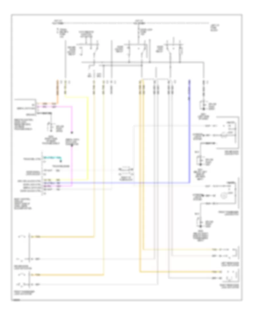
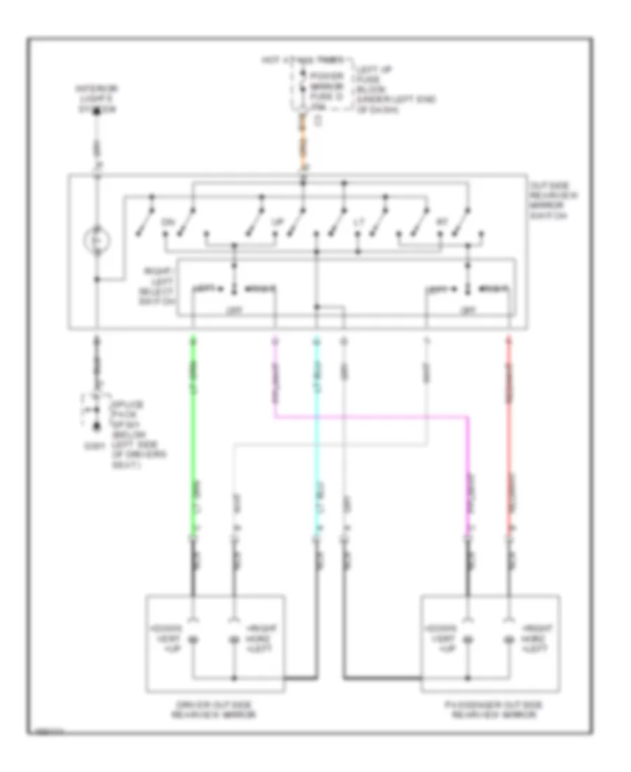
Power Mirror Wiring Diagram for Chevrolet Malibu 2002
List of elements for Power Mirror Wiring Diagram for Chevrolet Malibu 2002:
- +down vert +up
- +right horz +left
- B10
- Driver outside rearview mirror
- G301
- Hot at all times
- Interior lights system
- Left
- Left i/p fuse block (under left end of dash)
- Nca
- Off
- Outside rearview mirror switch
- Passenger outside rearview mirror
- Power mirror fuse d 10a
- Right
- Right/ left select switch
- Splice pack sp301 (below left side of driver's seat)
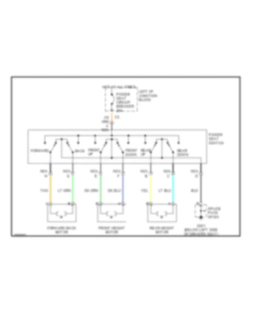
POWER SEATS
Power Seat Wiring Diagrams for Chevrolet Malibu 2002
List of elements for Power Seat Wiring Diagrams for Chevrolet Malibu 2002:
- Back
- Forward
- Forward back motor
- Front down
- Front height motor
- Front up
- G301 (below left side of driver's seat)
- Hot at all times
- Left i/p junction block
- Nca
- Power seat circuit breaker 25a
- Power seat switch
- Rear down
- Rear height motor
- Rear up
- Splice pack sp301
- Tan
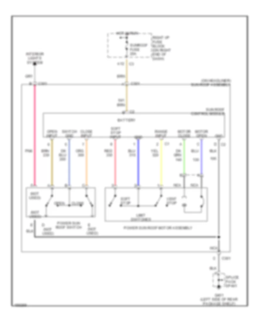
POWER TOP/SUNROOF
Power Top/Sunroof Wiring Diagrams for Chevrolet Malibu 2002
List of elements for Power Top/Sunroof Wiring Diagrams for Chevrolet Malibu 2002:
- (not used)
- (on headliner) sun roof assembly
- A12
- Battery
- C301
- Close
- Close input
- E (not used)
- G401 (left side of rear package shelf)
- Gnd
- Hot in run
- Interior lights system
- Limit switches
- Motor close
- Motor open
- Nca
- Open
- Open input
- Pnk
- Power sun roof motor assembly
- Power sun roof switch
- Range input
- Red
- Right i/p fuse block (on right end of dash)
- Soft stop
- Soft stop input
- Splice pack sp401
- Sun roof control module
- Sunroof fuse 20a
- Switch gnd
- Vent stop
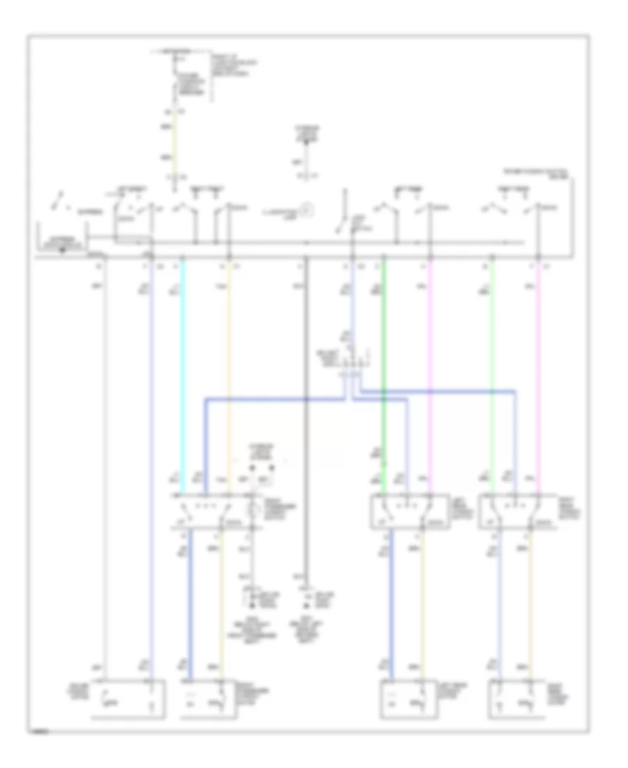
POWER WINDOWS
Power Window Wiring Diagram for Chevrolet Malibu 2002
List of elements for Power Window Wiring Diagram for Chevrolet Malibu 2002:
- Down
- Driver window motor
- Ecb
- Express
- Express down module
- Front passenger window motor
- Front passenger window switch
- G301 (below left side of driver's seat)
- G302 (below right side of front passenger seat)
- Hot in run
- Illumination lamp
- Interior lights system
- Left front
- Left rear
- Left rear window motor
- Left rear window switch
- Lock out switch
- Power window switch- driver
- Power windows circuit breaker
- Right front
- Right i/p junction block (on right end of dash)
- Right rear
- Right rear window motor
- Right rear window switch
- Splice pack s303
- Splice pack sp301
- Splice pack sp302
- Tan
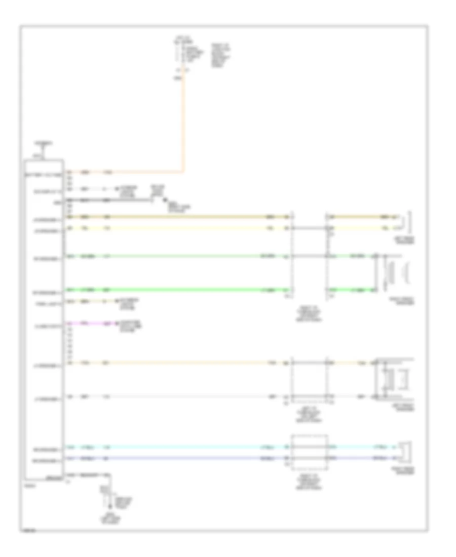
RADIO
Radio Wiring Diagrams for Chevrolet Malibu 2002
List of elements for Radio Wiring Diagrams for Chevrolet Malibu 2002:
- A10
- A11
- A12
- Antenna
- B10
- B11
- B12
- Battery voltage
- C1 a1
- C10
- C12
- Class 2 data
- Computer data lines system
- Dim display in
- Exterior lights system
- G202 (left side of dash)
- G203 (right side of dahs)
- Grd
- Ground
- Ground splice pack
- Hot at all times
- Interior lights system
- Left front speaker
- Left i/p fuse block (on left end of dash)
- Left rear speaker
- Lf speaker (+)
- Lf speaker (-)
- Lr speaker (+)
- Lr speaker (-)
- Nca
- Park lamp in
- Radio
- Radio battery fuse g 10a
- Rf speaker (+)
- Rf speaker (-)
- Right front speaker
- Right i/p fuse block (on right end of dash)
- Right i/p junction block (on right end of dash)
- Right rear speaker
- Rr speaker (+)
- Rr speaker (-)
- Splice pack sp203
- Tan
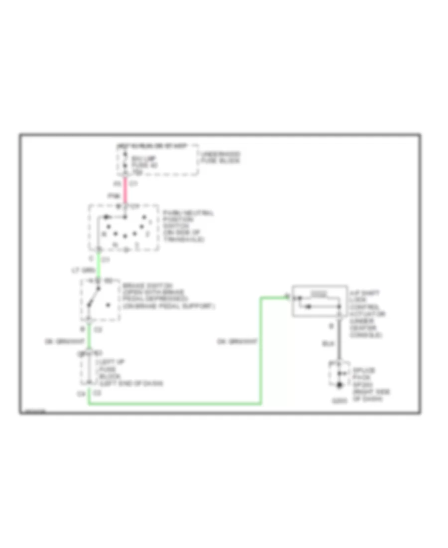
SHIFT INTERLOCKS
Shift Interlock Wiring Diagram for Chevrolet Malibu 2002
List of elements for Shift Interlock Wiring Diagram for Chevrolet Malibu 2002:
- A/f shift lock control actuator (under center console)
- B/u lmp fuse 42 15a
- Brake switch (open with brake pedal depressed) (on brake pedal support)
- G203
- Hot in run or start
- Left i/p fuse block (left end of dash)
- Park/ neutral position switch (on side of transaxle)
- Pnk
- Splice pack sp203 (right side of dash)
- Underhood fuse block
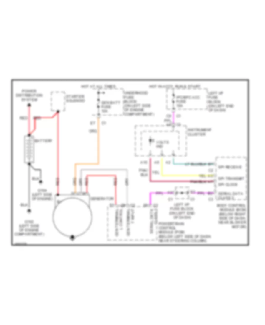
STARTING/CHARGING
Charging Wiring Diagram for Chevrolet Malibu 2002
List of elements for Charging Wiring Diagram for Chevrolet Malibu 2002:
- A10
- Battery
- Body control module (bcm) (below right side of dash, near blower motor)
- F input gen terminal
- G102 (left side of engine compartment)
- G104 (left side of engine)
- Gen batt fuse 10a
- Gen terminal l control
- Generator
- Hot at all times
- Hot in accy, run & start
- Instrument cluster
- Ipc/bfc acc fuse 10a
- Left i/p fuse block (on left end of dash)
- Power distribution system
- Powertrain control module (pcm) (below left side of dash, near steering column)
- Red
- Serial data class 2
- Spi clock
- Spi receive
- Spi transmit
- Starter solenoid
- Underhood fuse block (on left side of engine compartment)
- Volts ind
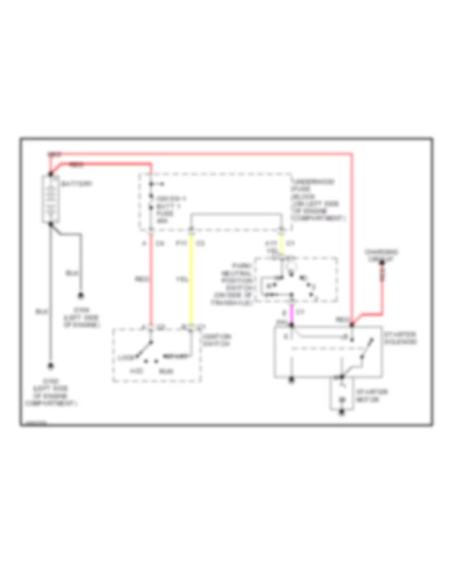
Starting Wiring Diagram for Chevrolet Malibu 2002
List of elements for Starting Wiring Diagram for Chevrolet Malibu 2002:
- Acc
- Battery
- Charging circuit
- F11
- G102 (left side of engine compartment)
- G104 (left side of engine)
- Ign sw-1 batt 1 fuse 40a
- Ignition switch
- Lock
- Park/ neutral position switch (on side of transaxle)
- Red
- Run
- Start
- Starter motor
- Starter solenoid
- Underhood fuse block (on left side of engine compartment)
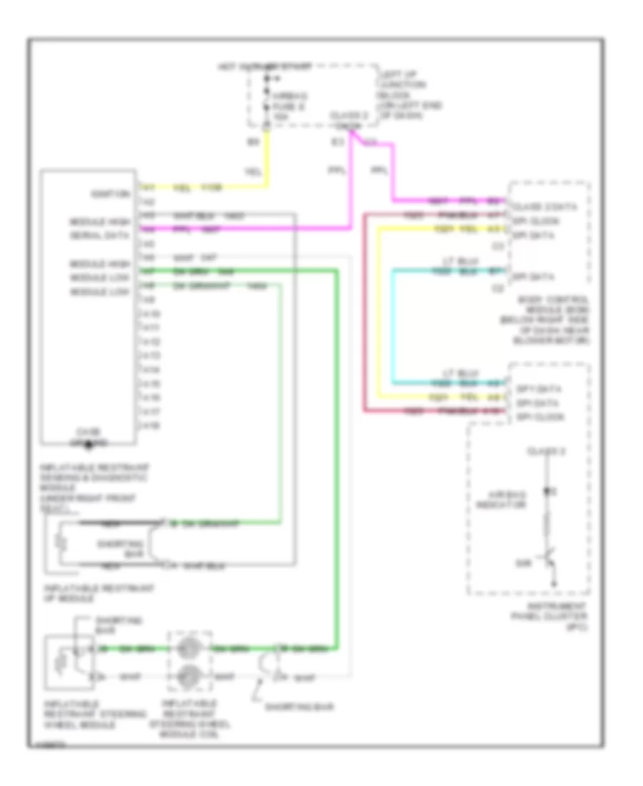
SUPPLEMENTAL RESTRAINTS
Supplemental Restraint Wiring Diagram for Chevrolet Malibu 2002
List of elements for Supplemental Restraint Wiring Diagram for Chevrolet Malibu 2002:
- A10
- A11
- A12
- A13
- A14
- A15
- A16
- A17
- A18
- Air bag indicator
- Airbag fuse e 10a
- Body control module (bcm) (below right side of dash, near blower motor)
- Case ground
- Class 2
- Class 2 data
- Hot in on or start
- Ignition
- Inflatable restraint i/p module
- Inflatable restraint sensing & diagnostic module (under right front seat)
- Inflatable restraint steering wheel module
- Inflatable restraint steering wheel module coil
- Instrument panel cluster (ipc)
- Left i/p junction block (on left end of dash)
- Module high
- Module low
- Nca
- Serial data
- Shorting bar
- Sir
- Sp1 data
- Spi clock
- Spi data
TRANSMISSION
3.1L
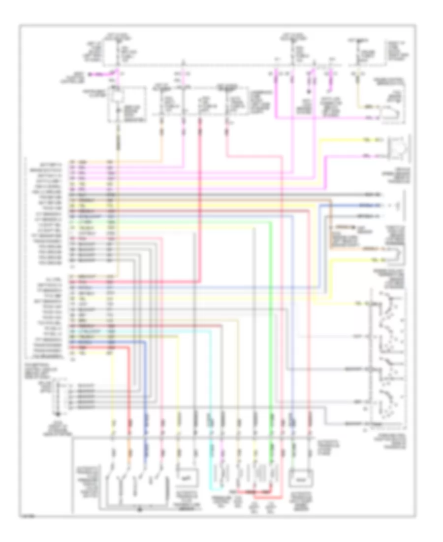
3.1L VIN J, A/T Wiring Diagram for Chevrolet Malibu 2002
List of elements for 3.1L VIN J, A/T Wiring Diagram for Chevrolet Malibu 2002:
- 1-2 shift sol
- 2-3 shift sol
- A/t sensor hi
- A/t sensor lo
- Anti- lock brakes system
- Auto trans fuse 38 10a
- Automatic transaxle (4t40-e/ 4t45-e)
- Automatic transaxle fluid pressure manual valve position switch
- Automatic transaxle fluid temperature sensor
- Automatic transaxle input shaft speed sensor
- B11
- B12
- Battery in
- Body function controller
- Brake switch in
- C1 d2
- Cruise control brake switch
- Cruise fuse d 10a
- Data class ii
- Data link connector (below left side of dash)
- Ect return
- Ect sensor in
- Engine coolant temperature sensor (top rear of engine)
- G102 (front of of engine, near starter)
- Gnd
- Hot at all times
- Hot in acc, run or start
- Hot in run
- Hot in run or start
- Ignition (1) in
- Ignition (2) in
- Instrument cluster
- Ipc/ bfc acc fuse j 10a
- Left i/p fuse block (left end of dash)
- Map sensor
- Mil ctrl
- P,r,n,lo,d4
- Park/neutral position switch (side of transaxle)
- Pc sol hi
- Pc sol lo
- Pcm acc fuse g 10a
- Pcm batt fuse 44 10a
- Pcm ground
- Pcm ign fuse 39 10a
- Pnk
- Powertrain control module (behind left side of dash)
- Pressure control sol
- Red
- Rev,d,2,1
- Right i/p fuse block (right end of dash)
- S102 (engine harn, left rear of engine compt)
- Service engine soon indicator
- Splice pack sp102
- Tan
- Tcc pwm sol
- Tcc release
- Tcc release in
- Tcc/ brake switch
- Tft sensor gnd
- Tft sensor in
- Throttle position sensor (top rear of engine)
- Tp 5v ref
- Tp sensor in
- Tps return
- Tr sw in-a
- Tr sw in-b
- Tr sw in-c
- Tr sw in-p
- Trans range a
- Trans range b
- Trans range c
- Underhood fuse block (left side of engine compt)
- Vehicle speed sensor (rear of transaxle)
- Vss hi (signal)
- Vss lo (ground)
TRUNK, TAILGATE, FUEL DOOR
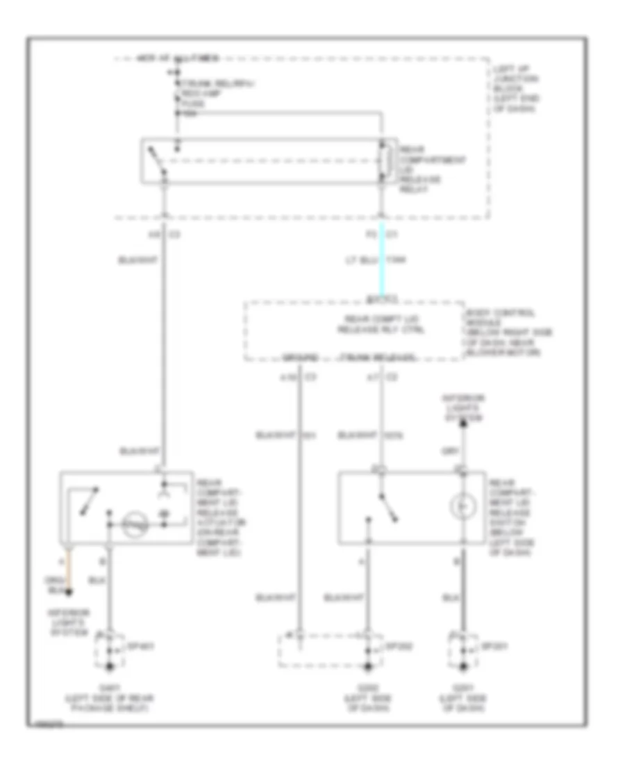
Trunk Release Wiring Diagram for Chevrolet Malibu 2002
List of elements for Trunk Release Wiring Diagram for Chevrolet Malibu 2002:
- A10
- A9 c3
- Body control module (below right side of dash, near blower motor)
- C1 f3
- G201 (left side of dash)
- G202 (left side of dash)
- G401 (left side of rear package shelf)
- Ground
- Hot at all times
- Interior lights system
- Left i/p junction block (left end of dash)
- Rear compart- ment lid release actuator (on rear compart- ment lid)
- Rear compart- ment lid release switch (below left side of dash)
- Rear compartment lid release relay
- Rear compt lid release rly ctrl
- Sp201
- Sp202
- Sp401
- Trunk rel/rfa/ rdo amp fuse 10a
- Trunk release
WARNING SYSTEMS
Warning System Wiring Diagrams for Chevrolet Malibu 2002
List of elements for Warning System Wiring Diagrams for Chevrolet Malibu 2002:
- (below right side of front passenger's seat)
- A/c bfc fuse 10a
- A10
- A11
- A12
- Alc
- B10
- B11
- B12
- B5 c3
- Battery positive voltage
- Bfc batt fuse 10a
- Body control module (bcm) (below right side of dash, near blower motor)
- C12
- C5 c3
- Computer data lines system
- Cruise fuse 10a
- Driver door ajar switch
- Front passenger door ajar switch
- G202 (left side of dash)
- G301 (below left side of driver's seat)
- G302
- G302 (below left side of driver's seat)
- Ground
- Hot at all times
- Hot in accy run, or start
- Hot in run
- Hot in run & start
- Ignition 0 positive voltage
- Ignition 1 positive voltage
- Ignition 3 positive voltage
- Ignition switch (key warning switch)
- Instrument panel cluster (ipc)
- Int lps fuse 10a
- Interior lamps control
- Interior lights system
- Ipc/bfc acc fuse 10a
- Key in ignition input
- Left front door ajar input
- Left i/p fuse block (on left end of dash)
- Left rear door ajar switch
- Nca
- Off
- Other door ajar input
- Park brake input
- Park brake switch (on left side of passenger compt)
- Park lps fuse 15a
- Pnk
- Right i/p fuse block (on right end of dash)
- Right i/p junc- tion block
- Right rear door ajar switch
- Seat belt switch (in driver's seat belt assembly)
- Seat belt switch input
- Serial data (class 2)
- Serial data spi clk
- Serial data spi clock
- Serial data spi data receive
- Serial data spi data transmit
- Serial data spi recei
- Serial data spi trans
- Splice pack sp202
- Splice pack sp301
- Splice pack sp302
- Turn signal multifunction switch
- Underhood fuse block (on left side of engine compt)
WIPER/WASHER
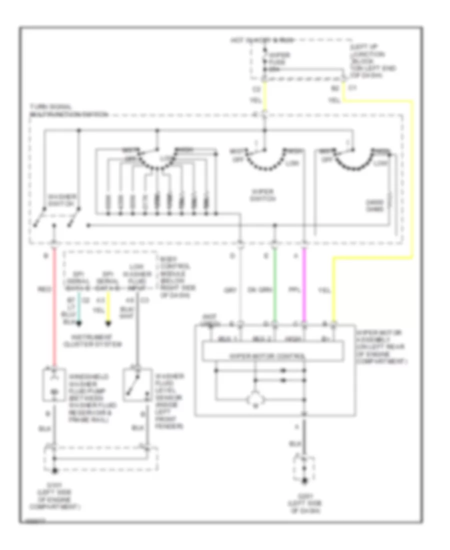
Wiper/Washer Wiring Diagram for Chevrolet Malibu 2002
List of elements for Wiper/Washer Wiring Diagram for Chevrolet Malibu 2002:
- (not used)
- 110k
- 155k
- 217k
- 305k
- 39k
- 430k
- 55k
- 680k
- 75k
- Body control module (below right side of dash)
- G101 (left side of engine compartment)
- G201 (left side of dash)
- High
- Hot in accy & run
- Instrument cluster system
- Left i/p junction block (on left end of dash)
- Low
- Low washer fluid input
- Mist
- Mux 1
- Mux 2
- Off
- Ohms
- Red
- Spi serial data b
- Turn signal multifunction switch
- Washer fluid level sensor (inside left front fender)
- Washer switch
- Windshield washer fluid pump (between washer fluid reservoir & frame rail)
- Wiper fuse 25a
- Wiper motor assembly (on left rear of engine compartment)
- Wiper motor control
- Wiper switch

 Čeština
 Dansk
Dansk Deutsch
 Ελληνικά
 English
 English
 Español
 Suomi
Suomi Français
 עברית
עברית Hrvatski
 Magyar
 Italiano
 日本語
日本語 한국어
한국어 Nederlands
 Polski
 Português
 Português
 Română
 Русский
 Slovenčina
 Slovenščina
 Svenska
 Türkçe
 中文 (中国)