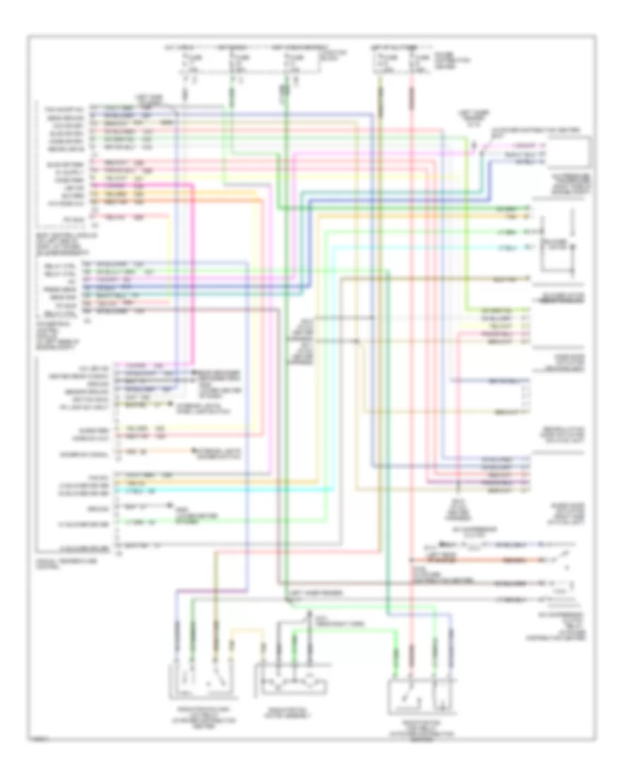
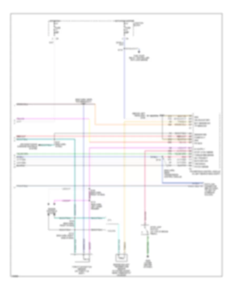
AIR CONDITIONING
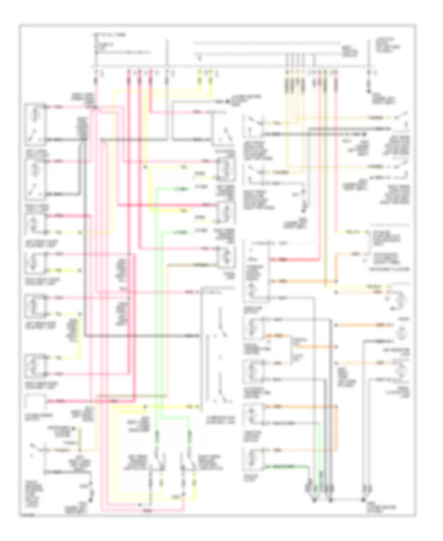
Air Conditioning Wiring Diagrams, Auto A/C for Dodge Intrepid 1998
 https://portal-diagnostov.com/license.html
Automotive Electricians Portal FZCO
Automotive Electricians Portal FZCO
https://portal-diagnostov.com/license.html
https://portal-diagnostov.com/license.html
Automotive Electricians Portal FZCO
Automotive Electricians Portal FZCO
List of elements for Air Conditioning Wiring Diagrams, Auto A/C for Dodge Intrepid 1998:
- (in a/c heater harness) s212
- (in power distribution center)
- (left inner fender)
- (left rear of engine)
- (left side of dash)
- (lower center of dash) g200
- +5v
- A/c compressor clutch
- A/c compressor clutch relay
- A/c pressure transducer (right side of radiator)
- Amb temp
- Ambient temperature sensor (front grille area)
- Aspirator mtr
- Atc motor
- Atc power module (right side of hvac housing)
- Automatic temperature control
- Blend door actuator (right side of hvac unit)
- Blnd dr drv
- Blnd dr fdbk
- Blower motor
- Blwr mtr ctrl
- Body control module (on left end of dash, attached to junction block)
- C10
- C12
- C18
- C24
- C26
- C27
- C28
- C32
- C33
- C34
- C35
- C36
- C37
- C38
- C56
- C57
- Com dr drv
- D25
- Data link connector (left side of steering column)
- Dimmer sw input
- Evap temp sens
- Evaporator temperature sensor (in evaporator)
- F20
- Fuse 10a
- Fuse 30a
- Fuse b 30a
- Fuse e 30a
- G101 (near right horn)
- G114
- G200 (lower center of dash)
- G31
- Ground
- Hot at all times
- Hot in run
- Hot in run or start
- Ignition
- In car temp
- In-car temp sens
- Interior lights system
- Junction block
- Mode door actuator (on hvac unit)
- Mode dr drv
- Mode fdbk
- Nca
- Pci bus
- Pnk
- Power distribution center
- Powertrain control module (in left rear of engine compt)
- Press sens
- Radiator fan high relay (in power distribution center)
- Radiator fan high/ low relay (in power distribution center)
- Radiator fan motor assembly
- Recirc drive
- Recirculation door actuator (on hvac unit)
- Red/tan
- Relay ctrl
- S117 (left inner fender)
- S118
- S125 (in power distribution center)
- S127
- S204
- S208 (left side of dash)
- S210 (in a/c heater harness)
- S211 (in a/c heater harness)
- Sens gnd
- Sens ground
- Sun sens
- Sun sensor/ vtss set led (top center of dash)
- Tan
Air Conditioning Wiring Diagrams, Manual A/C for Dodge Intrepid 1998
List of elements for Air Conditioning Wiring Diagrams, Manual A/C for Dodge Intrepid 1998:
- (in power distribution center)
- (in power distribution center) s127
- (left inner fender)
- (left inner fender) s118
- (left rear of engine)
- (left side of dash)
- +5v
- A/c compressor clutch
- A/c compressor clutch relay
- A/c led ind
- A/c mode mux
- A/c pressure transducer (right side of engine compt)
- Bld req
- Blend door actuator (right side of hvac unit)
- Blend req
- Blnd dr drv
- Blnd dr fdbk
- Blower motor
- Blower motor resistor block
- Body control module (on left end of dash, attached to junction block)
- C10
- C18
- C24
- C26
- C27
- C28
- C32
- C33
- C34
- C35
- C36
- C37
- C48
- C57
- C58
- C59
- C80
- C82
- Com dr drv
- D25
- Dimmer sw signal
- F20
- Fan on/off sw
- Fan sw
- Fuse 10a
- Fuse 30a
- Fuse b 30a
- Fuse e 30a
- G101 (near right horn)
- G114
- G206 (lower center of dash)
- Ground
- Heated rear window
- Hi blower driver
- Hot at all times
- Hot in run
- Hot in run or start
- Ignition (run)
- Interior lights (dimmer switch)
- Interior lights (park lamp switch)
- Junction block
- Led ind
- Lo blower driver
- M1 blower driver
- M2 blower driver
- Manual temperature control
- Mode door actuator (on hvac unit)
- Mode dr drv
- Mode fdbk
- Mode sw mux
- Pci bus
- Pk lamp sw input
- Power distribution center
- Powertrain control module (in left rear of engine compt)
- Press sens
- Radiator fan high relay (in power distribution center)
- Radiator fan high/ low relay (in power distribution center)
- Radiator fan motor assembly
- Rear defogger (defogger grid)
- Recirc drive
- Recirculation door actuator (on hvac unit)
- Red/tan
- Relay ctrl
- S117
- S125 (in power distribution center)
- S208
- S210 (in a/c heater harness)
- S211 (in a/c heater harness)
- S212 (in a/c heater harness)
- Sens gnd
- Sens ground
- Sensor ground
- Tan
ANTI-LOCK BRAKES
Anti-lock Brake Wiring Diagrams for Dodge Intrepid 1998
List of elements for Anti-lock Brake Wiring Diagrams for Dodge Intrepid 1998:
- A10
- A20
- Battery
- Body control module
- Controller anti-lock brake (at left fender side shield, on bottom of hydraulic control unit)
- D25
- F20
- Fuse 17 10a
- Fuse 20 20a
- Fuse h 30a
- Fuse k 40a
- G106 (behind left headlamp)
- Ground
- Hot at all times
- Hot at hot in run
- Ignition
- Junction block
- L50
- Left front wheel speed sensor (on left steering knuckle boss)
- Left rear wheel speed sensor (on left rear caliper adapter)
- Lt ft whl spd
- Lt rear whl spd
- Pci bus
- Power distribution center
- Red
- Red/tan
- Right front wheel speed sensor (on right steering knuckle boss)
- Right rear wheel speed sensor (on right rear caliper adapter)
- Rt ft whl spd
- Rt rear whl spd
- S205 (i/p harn, left side of instrument panel)
- Stop lamp sw out
- Stop lamp switch (top of brake pedal)
ANTI-THEFT
Anti-theft Wiring Diagram for Dodge Intrepid 1998
List of elements for Anti-theft Wiring Diagram for Dodge Intrepid 1998:
- (engine compt harn, near breakout to left front headlight)
- Body control module
- C57
- D25
- Deck lid ground
- Door ajar sense
- Door lock sense
- Fuse 10a
- Fuse 20a
- Fused b (+)
- Fused ign
- G106 (behind left headlamp)
- G119 (right front of engine compt)
- G206 (lower center of dash)
- G26
- G300 (under left front seat)
- G303 (under right rear seat)
- G71
- G72
- G73
- G74
- G75
- Ground
- Horn relay
- Horn rly ctrl
- Horn system (horn switch)
- Hot at all times
- Hot in run or start
- Ignition switch (key-in switch)
- Junction block (at left end of dash)
- Key-in switch
- Knock out switch
- Left front door ajar switch/ lock motor
- Left front door lock cylinder switch
- Left horn (left front engine compt)
- Left rear door ajar switch/ lock motor
- Low beam headlamp relay
- Low beam rly ctrl
- Park lamp relay
- Parklamp rly ctrl
- Pci bus
- Pnk
- Right front door ajar switch/ lock motor
- Right front door lock cylinder switch
- Right horn (right front engine compt)
- Right rear door ajar switch/ lock motor
- S133
- S134
- S135
- S200
- S204
- S301
- S311
- S312
- S313
- S314
- S405
- Sentry key immobilier module (in steering column)
- Sun sensor/ vtss set led (top center of inst panel)
- Tan
- Tan/ red
- Tan/red
- Trunk knock out switch
- Vtss lamp driver
- Z20
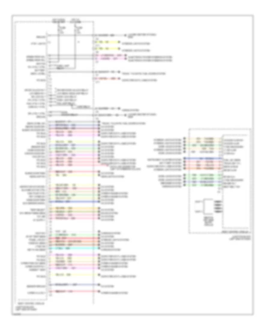
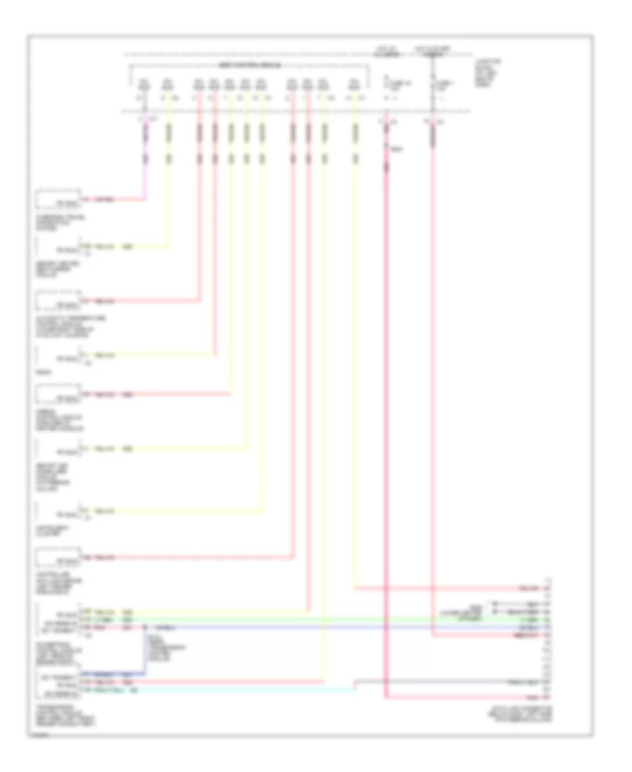
BODY COMPUTER
Body Computer Wiring Diagrams for Dodge Intrepid 1998
List of elements for Body Computer Wiring Diagrams for Dodge Intrepid 1998:
- (lower center of dash) g206
- A/c led
- A/c system
- Ambient temp
- Anti-theft system
- Aspirator motor drv
- Battery
- Blend air door drv
- Blend door fdbk
- Blower motor ctrl
- Body control module
- C10 (or c58)
- C11
- C12
- C26
- C32
- C33
- C34
- C35
- C36
- C37
- C38
- C48
- C56
- C57
- C80
- C82
- Common door drv
- Computer data lines system
- Ctsy lights
- D25
- Data link connector (left of steering column)
- Day brightness sens
- Deck lid rel
- Decklid bus
- Decklid rel sw
- Defogger system
- Door lock relay
- Door locks system
- Door unlock relay
- Dr dr unlock rly
- Dr lk rly ctrl
- Dr lock rly
- Driver door unlock relay
- E17
- E19
- Electronic power steering system
- Evap temp sens
- Fan off sw
- Fog lamp relay
- Fog lp rly ctrl
- Frt wiper sw
- Fuel lev sens
- Fuse 10a
- G10
- G26
- G31
- G52
- G69
- G71
- G72
- G73
- G74
- G75
- Ground
- Hdlp sw
- Headlamp sw
- Headlights system
- Horn relay
- Horn rly ctrl
- Horns system
- Hot at all times
- Hot in run and start
- Ignition
- Instrument cluster system
- Interior lights system
- Junction block (left end of dash)
- Key-in ign sens
- L80
- Lf dr mux
- Low beam headlamp relay
- Low beam rly
- Lr door ajar
- Lr door ajar sw
- Lt dr ajar
- Mode door drv
- Mode door fdbk
- Mode sw sens
- Nca
- P96
- P97
- Panel lps sw
- Park lamp relay
- Pci bus
- Pk lp rly ctrl
- Recirc door drv
- Red
- Red/tan
- Remote keyless entry module
- Rf dr mux
- Rr def rly
- Rr dr ajar
- S76
- S77
- Seat belt sw
- Sensor gnd
- Sensor ground
- Sound system
- Speed prop sol
- Sun sensor signal
- Tan
- Tan/red
- Temp select
- Trunk key cyl
- Trunk, tailgate, fuel doors system
- V10
- V14
- V16
- V52
- V55
- Vtss arm/disarm
- Vtss ind
- Warning system
- Wiper hi/lo rly
- Wiper on/off rly
- Wiper park sw sens
- Wiper/washer system
- Wsh pump ctrl
- Z20
COMPUTER DATA LINES
Computer Data Lines for Dodge Intrepid 1998
List of elements for Computer Data Lines for Dodge Intrepid 1998:
- Airbag control module (forward of center console)
- Automatic temperature control module (lower right side of hvac unit housing)
- Body control module
- C11
- Controller anti-lock brake (left fender side shield)
- D20
- D21
- D25
- Data link connector (below dash, left side of steering column)
- Fuse 1 10a
- Fuse 19 10a
- G206 (lower center of dash)
- Hot at all times
- Hot in start and run
- Instrument cluster
- Junction block (at left end of dash)
- Memory heated seat/mirror module
- Overhead travel information system
- Pci bus
- Pnk
- Powertrain control module (left rear of engine compt)
- Radio
- S115 (near transmission control module)
- S204
- Sci receive
- Sci transmit
- Sentry key immobilizer module (in steering column)
- Transmission control module (between left front fender and battery)
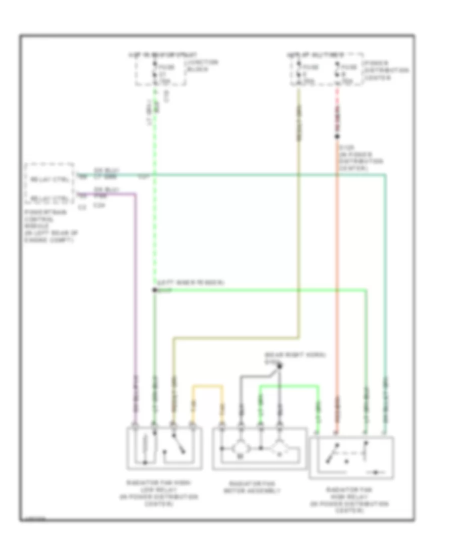
COOLING FAN
Cooling Fan Wiring Diagram for Dodge Intrepid 1998
List of elements for Cooling Fan Wiring Diagram for Dodge Intrepid 1998:
- (left inner fender)
- (near right horn) g101
- C10
- C24
- C27
- Fuse 10a
- Fuse b 30a
- Fuse e 30a
- Hot at all times
- Hot in run or start
- Junction block
- Power distribution center
- Powertrain control module (in left rear of engine compt)
- Radiator fan high relay (in power distribution center)
- Radiator fan high/ low relay (in power distribution center)
- Radiator fan motor assembly
- Relay ctrl
- S117
- S125 (in power distribution center)
- Tan
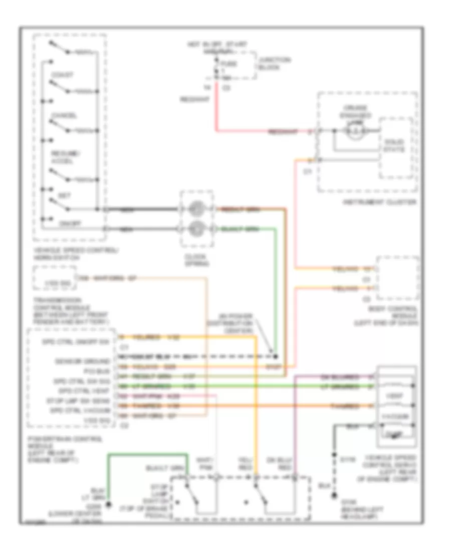
CRUISE CONTROL
Cruise Control Wiring Diagram for Dodge Intrepid 1998
List of elements for Cruise Control Wiring Diagram for Dodge Intrepid 1998:
- (in power distribution center)
- Body control module (left end of dash)
- Cancel
- Clock spring
- Coast
- Cruise engaged lamp
- D25
- Dump
- Fuse 10a
- G106 (behind left headlamp)
- G206 (lower center of dash)
- Hot in off, start and run
- Instrument cluster
- Junction block
- K29
- Nca
- On/off
- Pci bus
- Powertrain control module (left rear of engine compt)
- Resume/ accel
- S119
- S127
- Sensor ground
- Set
- Solid state
- Spd ctrl on/off sw
- Spd ctrl sw sig
- Spd ctrl vacuum
- Spd ctrl vent
- Stop lamp switch (top of brake pedal)
- Stop lmp sw sens
- Tan/red
- Transmission control module (between left front fender and battery)
- V32
- V35
- V36
- V37
- Vacuum
- Vehicle speed control servo (left rear of engine compt)
- Vehicle speed control/ horn switch
- Vent
- Vss sig
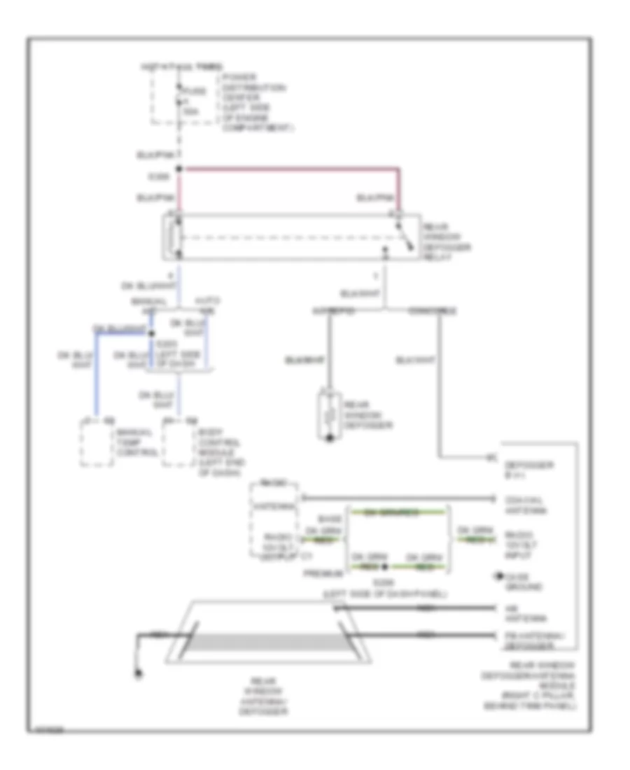
DEFOGGERS
Defogger Wiring Diagram for Dodge Intrepid 1998
List of elements for Defogger Wiring Diagram for Dodge Intrepid 1998:
- (left side of dash panel)
- Am antenna
- Antenna
- Auto a/c
- Base
- Body control module (left end of dash)
- Case ground
- Coaxial antenna
- Concorde
- Defogger b (+)
- Fm antenna/ defogger
- Fuse a 50a
- Hot at all times
- Intrepid
- Manual a/c
- Manual temp control
- Nca
- Of dash
- Power distribution center (left side of engine compartment)
- Premium
- Radio
- Radio 12volt input
- Radio 12volt output
- Rear window antenna/ defogger
- Rear window defogger
- Rear window defogger relay
- Rear window defogger/antenna module (right c pillar, behind trim panel)
- S206
- S306
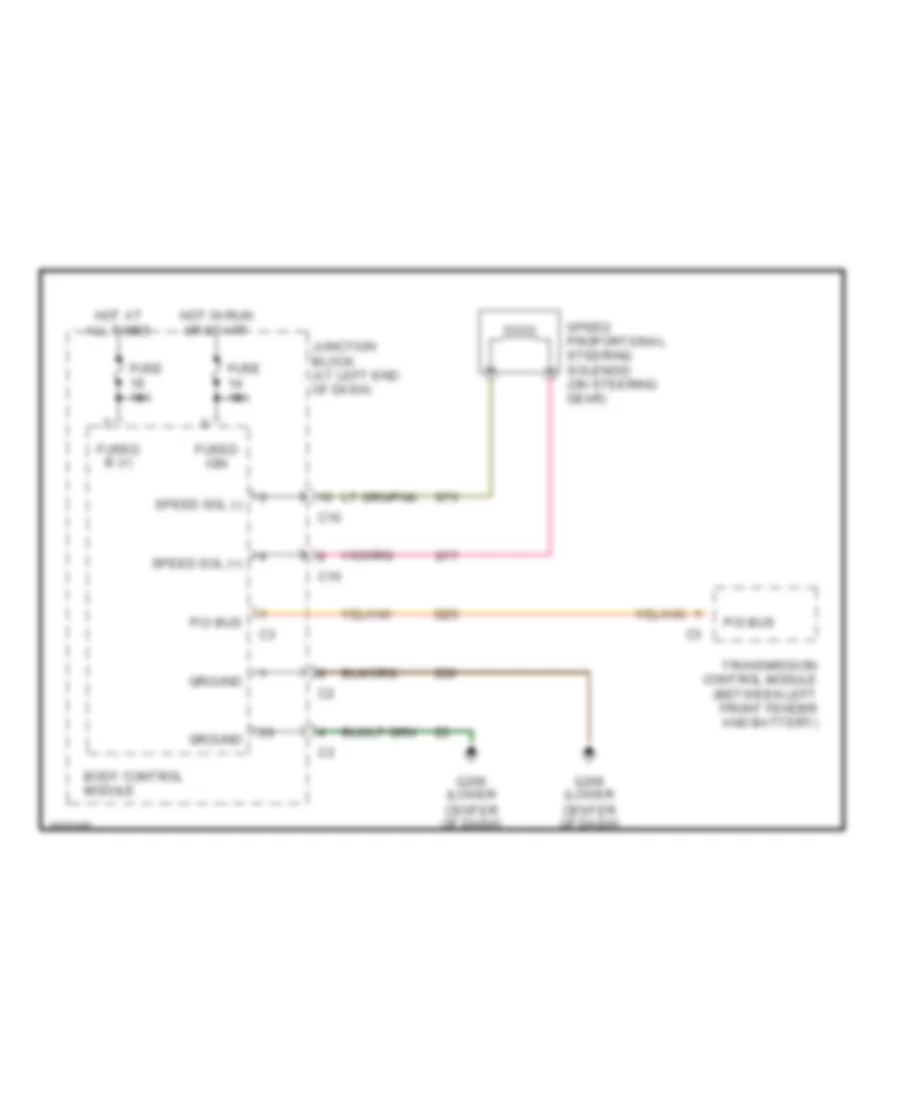
ELECTRONIC POWER STEERING
Electronic Power Steering Wiring Diagram for Dodge Intrepid 1998
List of elements for Electronic Power Steering Wiring Diagram for Dodge Intrepid 1998:
- Body control module
- C10
- D25
- Fuse 10a
- Fused b (+)
- Fused ign
- G206 (lower center of dash)
- Ground
- Hot at all times
- Hot in run or start
- Junction block (at left end of dash)
- Pci bus
- S76
- S77
- Speed proportional steering solenoid (on steering gear)
- Speed sol (+)
- Speed sol (-)
- Transmission control module (between left front fender and battery)
- Z20
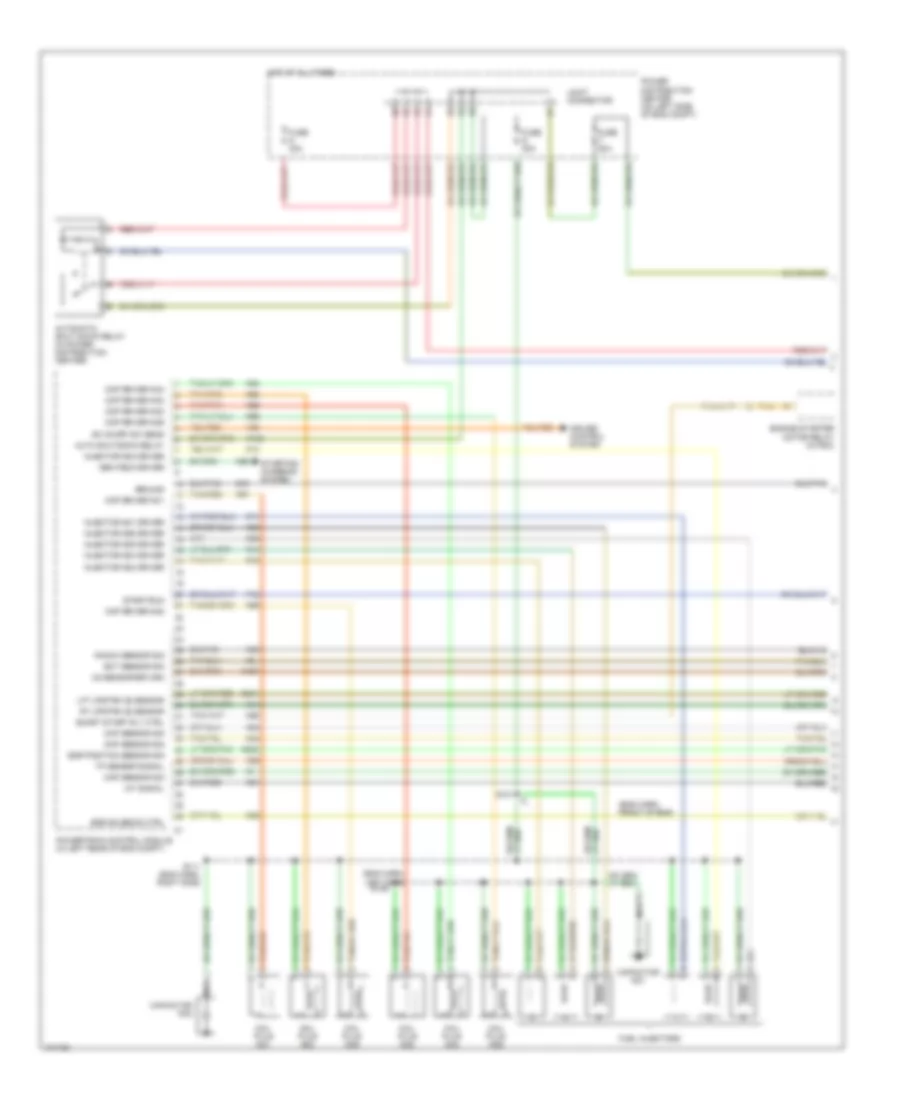
ENGINE PERFORMANCE
2.7L
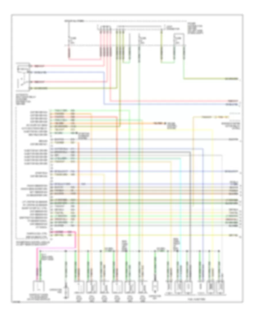
2.7L, Engine Performance Wiring Diagrams (1 of 3) for Dodge Intrepid 1998
List of elements for 2.7L, Engine Performance Wiring Diagrams (1 of 3) for Dodge Intrepid 1998:
- (eng harn, front of eng)
- (eng harn, left side)
- A142
- Auto shutdown relay
- Automatic shut down relay (in power distribution center)
- Capacitor no1
- Capacitor no2
- Ckp sensor sig
- Cmp sensor sig
- Coil plug no1
- Coil plug no2
- Coil plug no3
- Coil plug no4
- Coil plug no5
- Coil plug no6
- Cop driver no1
- Cop driver no2
- Cop driver no3
- Cop driver no4
- Cop driver no5
- Cop driver no6
- Cruise control system
- Ect sensor sig
- Egr position sensor sig
- Egr solenoid ctrl
- Engine starter motor relay (in pdc)
- F12
- Fuel injectors
- Fuse n 30a
- Fuse s 20a
- Fuse t 20a
- Gen field driver
- Ground
- Hot at all times
- Iat signal
- Injector no1 driver
- Injector no2 driver
- Injector no3 driver
- Injector no4 driver
- Injector no5 driver
- Injector no6 driver
- Joint connector
- K11
- K12
- K127
- K13
- K14
- K20
- K21
- K22
- K235
- K24
- K241
- K35
- K38
- K41
- K44
- K45
- K58
- K90
- K91
- K92
- K93
- K94
- K95
- K96
- Knock sensor sig
- Lft upstrm o2 sensor
- Map sensor sig
- Nca
- O2 sensor return
- Power distribution center (on left side of eng compt)
- Powertrain control module (in left rear of eng compt)
- Rt upstrm o2 sensor
- S101
- S109
- S111 (eng harn, right side)
- Sc on/off sw sens
- Smart start rly ctrl
- Start/run
- Starting/ charging system
- Tan
- Tan/pnk
- Tan/red
- Tp sensor signal
- V32
- Z12
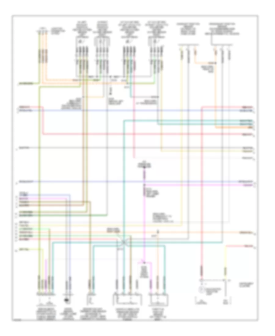
2.7L, Engine Performance Wiring Diagrams (2 of 3) for Dodge Intrepid 1998
List of elements for 2.7L, Engine Performance Wiring Diagrams (2 of 3) for Dodge Intrepid 1998:
- (at outlet end of left catalytic converter) heated oxygen sensor (left downstream)
- (at outlet end of right catalytic converter) heated oxygen sensor (right downstream)
- (eng harn, at transmission)
- (eng harn, front of eng)
- (eng harn, in breakout to powertrain control module)
- (eng harn, right side)
- (in left exhaust manifold) heated oxygen sensor (left upstream)
- (in right exhaust manifold) heated oxygen sensor (right upstream)
- A/c pressure transducer
- Camshaft position sensor (on front of eng's timing case cover)
- Crankshaft position sensor (on passenger's side of trans housing, above differential housing)
- Egr solenoid (on the rear of right cylinder head)
- Engine coolant temperature sensor (on engine, in water jacket, near thermostat housing)
- G106 (behind left headlamp)
- Instrument cluster
- Intake air temperature sensor (in intake manifold)
- Junction connector (in pdc)
- Knock sensor (in side of eng block)
- Malfunction indicator lamp
- Manifold absolute pressure sensor (on left side of intake manifold plenum)
- Mil control
- Nca
- Pci bus
- S100
- S102 (eng harn, in breakout for powertrain control module)
- S103
- S104
- S105
- S106
- S107
- S110
- S118 (eng harn, left inner fender)
- S123
- S141
- S142
- S143
- Throttle position sensor (on throttle body)
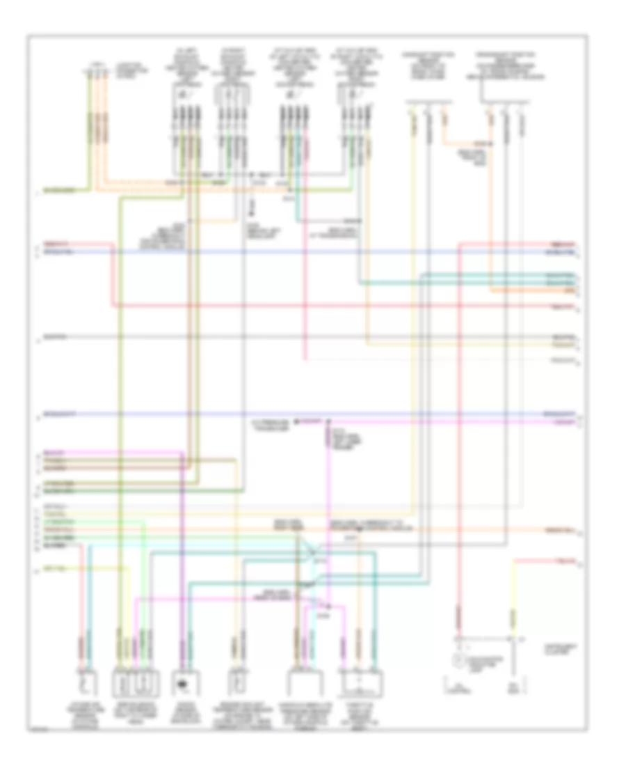
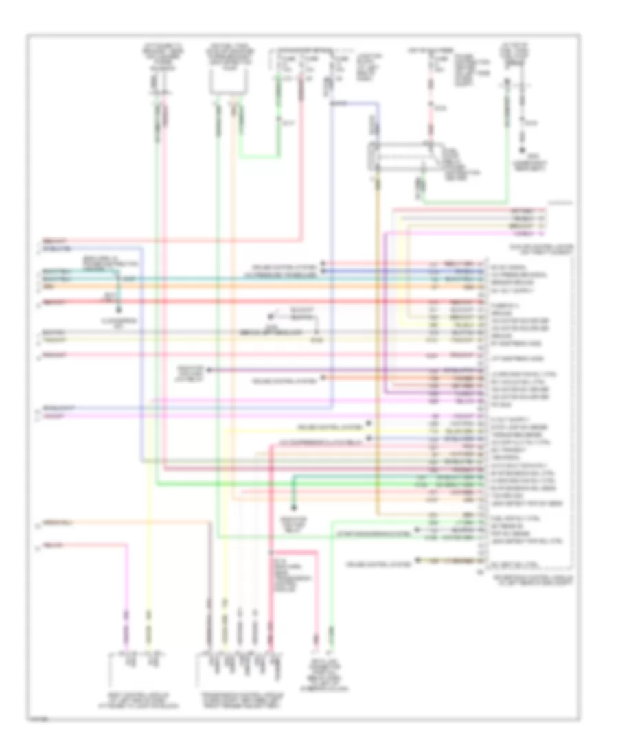
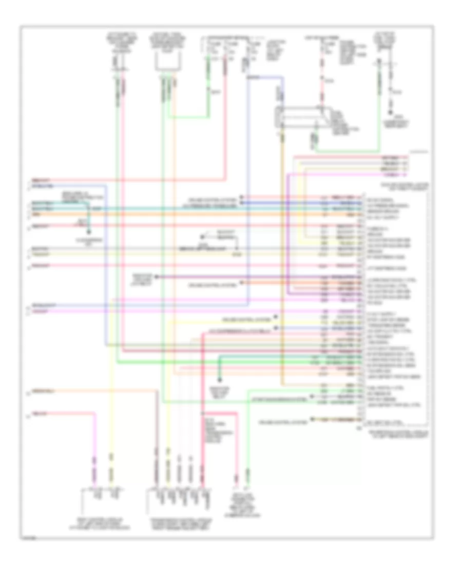
2.7L, Engine Performance Wiring Diagrams (3 of 3) for Dodge Intrepid 1998
List of elements for 2.7L, Engine Performance Wiring Diagrams (3 of 3) for Dodge Intrepid 1998:
- (attached to bracket, near air cleaner) purge solenoid
- (behind left headlamp)
- (eng harn, in power distribution center)
- (in top of fuel tank) fuel pump module
- (on fuel tank, on evap canister purge bracket) leak detection pump
- (under right rear seat)
- A/c cmp clut rly ctrl
- A/c compressor clutch relay
- A/c pressure signal
- A/c pressure transducer
- A14
- Auto shut down rly
- Body control module (at left end of dash, attached to junction block)
- Bus pci
- C18
- C2 c2
- C24
- C27
- C28
- Clockspring no1
- Cruise control system
- D20
- D21
- D25
- Data link connector (partial) (below dash, to left of steering column)
- Evap emission sol ctrl
- Evap emission sol sens
- Fuel pmp rly ctrl
- Fuel pump relay (power distribution center)
- Fuse 10a
- Fuse g 40a
- Fused b (+)
- G106
- G303
- Ground
- Hi spd rad fan rly ctrl
- Hot at all times
- Hot in start or run
- Iac motor no1 driver
- Iac motor no2 driver
- Iac motor no3 driver
- Iac motor no4 driver
- Idle air control motor (on throttle body)
- Junction block (at left end of dash)
- K106
- K107
- K108
- K141
- K22
- K29
- K31
- K341
- K39
- K40
- K51
- K52
- K59
- K60
- K71
- Leak detect pmp sol ctrl
- Leak detect pmp sw sens
- Lft dnstream ho2s
- Lo spd rad fan rly ctrl
- Pci bus
- Pnk
- Pnp sw sense
- Power distribution center (on left side of eng compt)
- Powertrain control module (in left rear of eng compt)
- Radiator fan high relay
- Radiator fan high/ low relay
- Red
- Req sense
- Rpm sig tcm
- Rt dnstream ho2s
- S115 (eng harn, near transmission control module)
- S116
- S117
- S122
- S124
- S127
- S140
- Sc sw signal
- Sc vacuum sol ctrl
- Sc vent sol ctrl
- Sci receive
- Sci transmit
- Sensor ground
- Signal tps
- Starting/charging system
- Stop lamp sw sense
- T10
- T41
- Tan/red
- Tcm rpm sig
- Torque req sense
- Transmission control module (in eng compt, between left front fender and battery)
- V35
- V36
- V37
- Vss signal
- Z11
- Z12
3.2L
3.2L, Engine Performance Wiring Diagrams (1 of 3) for Dodge Intrepid 1998
List of elements for 3.2L, Engine Performance Wiring Diagrams (1 of 3) for Dodge Intrepid 1998:
- (eng harn, front of eng)
- (eng harn, left side)
- A142
- Auto shutdown relay
- Automatic shut down relay (in power distribution center)
- Capacitor no1
- Capacitor no2
- Ckp sensor sig
- Cmp sensor sig
- Coil plug no1
- Coil plug no2
- Coil plug no3
- Coil plug no4
- Coil plug no5
- Coil plug no6
- Cop driver no1
- Cop driver no2
- Cop driver no3
- Cop driver no4
- Cop driver no5
- Cop driver no6
- Cruise control system
- Ect sensor sig
- Egr position sensor sig
- Egr solenoid ctrl
- Engine starter motor relay (in pdc)
- F12
- Fuel injectors
- Fuse n 30a
- Fuse s 20a
- Fuse t 20a
- Gen field driver
- Ground
- Hot at all times
- Iat signal
- Injector no 3 driver
- Injector no1 driver
- Injector no2 driver
- Injector no4 driver
- Injector no5 driver
- Injector no6 driver
- Joint connector
- K11
- K12
- K127
- K13
- K14
- K20
- K21
- K22
- K235
- K24
- K241
- K35
- K36
- K38
- K41
- K44
- K45
- K58
- K90
- K91
- K92
- K93
- K94
- K95
- K96
- Knock sens sig return
- Knock sensor sig
- Lft upstrm o2 sensor
- Manifold sol ctrl
- Manifold tuning valve solenoid (on intake manifold)
- Map sensor sig
- Nca
- O2 sensor return
- Power distribution center (on left side of eng compt)
- Powertrain control module (in left rear of eng compt)
- Rt upstrm o2 sensor
- S109
- S111 (eng harn, right side)
- S112
- Sc on/off sw sens
- Smart start rly ctrl
- Start/run
- Starting/ charging system
- Tan
- Tan/pnk
- Tan/red
- Tp sensor signal
- V32
- Z12
3.2L, Engine Performance Wiring Diagrams (2 of 3) for Dodge Intrepid 1998
List of elements for 3.2L, Engine Performance Wiring Diagrams (2 of 3) for Dodge Intrepid 1998:
- (at outlet end of left catalytic converter) heated oxygen sensor (left downstream)
- (at outlet end of right catalytic converter) heated oxygen sensor (right downstream)
- (eng harn, at transmission)
- (eng harn, front of eng)
- (eng harn, in breakout to powertrain control module)
- (eng harn, right side)
- (in left exhaust manifold) heated oxygen sensor (left upstream)
- (in right exhaust manifold) heated oxygen sensor (right upstream)
- A/c pressure tranducer
- Camshaft position sensor (on front of eng's timing case cover)
- Crankshaft position sensor (on passenger's side of trans housing, above differential housing)
- Egr solenoid (near bottom of intake manifold plenum, beside throttle body)
- Engine coolant temperature sensor (on engine, in water jacket, near thermostat housing)
- G106 (behind left headlamp)
- Instrument cluster
- Junction connector (in pdc)
- Knock sensor (under lower intake manifold)
- Malfunction indicator lamp
- Manifold absolute pressure sensor (on left side of intake manifold plenum)
- Mil control
- Nca
- Pci bus
- S100
- S102 (eng harn, in breakout for powertrain control module)
- S103
- S105
- S106
- S107
- S110
- S118 (eng harn, left inner fender)
- S123
- S141
- S142
- S143
- Throttle position sensor (on throttle body)
3.2L, Engine Performance Wiring Diagrams (3 of 3) for Dodge Intrepid 1998
List of elements for 3.2L, Engine Performance Wiring Diagrams (3 of 3) for Dodge Intrepid 1998:
- (attached to bracket, near air cleaner) purge solenoid
- (behind left headlamp)
- (eng harn, in power distribution center)
- (in top of fuel tank) fuel pump module
- (on fuel tank, on evap canister purge bracket) leak detection pump
- (under right rear seat)
- A/c cmp clut rly ctrl
- A/c compressor clutch relay
- A/c pressure signal
- A/c pressure transducer
- A14
- Auto shut down rly
- Body control module (at left end of dash, attached to junction block)
- C18
- C2 c2
- C24
- C27
- C28
- Clockspring no1
- Cruise control system
- D20
- D21
- D25
- Data link connector (partial) (below dash, to left of steering column)
- Evap emission sol ctrl
- Evap emission sol sens
- Fuel pmp rly ctrl
- Fuel pump relay (power distribution center)
- Fuse 10a
- Fuse g 40a
- Fused b (+)
- G106
- G303
- Ground
- Hi spd rad fan rly ctrl
- Hot at all times
- Hot in start or run
- Iac motor no1 driver
- Iac motor no2 driver
- Iac motor no3 driver
- Iac motor no4 driver
- Idle air control motor (on throttle body)
- Junction block (at left end of dash)
- K106
- K107
- K108
- K141
- K22
- K29
- K31
- K341
- K39
- K40
- K51
- K52
- K59
- K60
- K71
- Leak detect pmp sol ctrl
- Leak detect pmp sw sens
- Lft dnstream ho2s
- Lo spd rad fan rly ctrl
- Pci bus
- Pnk
- Pnp sw sense
- Power distribution center (on left side of eng compt)
- Powertrain control module (in left rear of eng compt)
- Radiator fan high relay
- Radiator fan high/ low relay
- Red
- Req sense
- Rpm sig tcm
- Rt dnstream ho2s
- S115 (eng harn, near transmission control module)
- S116
- S117 s117
- S122
- S124
- S127
- S140
- Sc sw signal
- Sc vacuum sol ctrl
- Sc vent sol ctrl
- Sci receive
- Sci transmit
- Sensor ground
- Signal tps
- Starting/charging system
- Stop lamp sw sense
- T10
- T41
- Tan/red
- Tcm rpm sig
- Torque req sense
- Transmission control module (in eng compt, between left front fender and battery)
- V35
- V36
- V37
- Vss signal
- Z11
- Z12
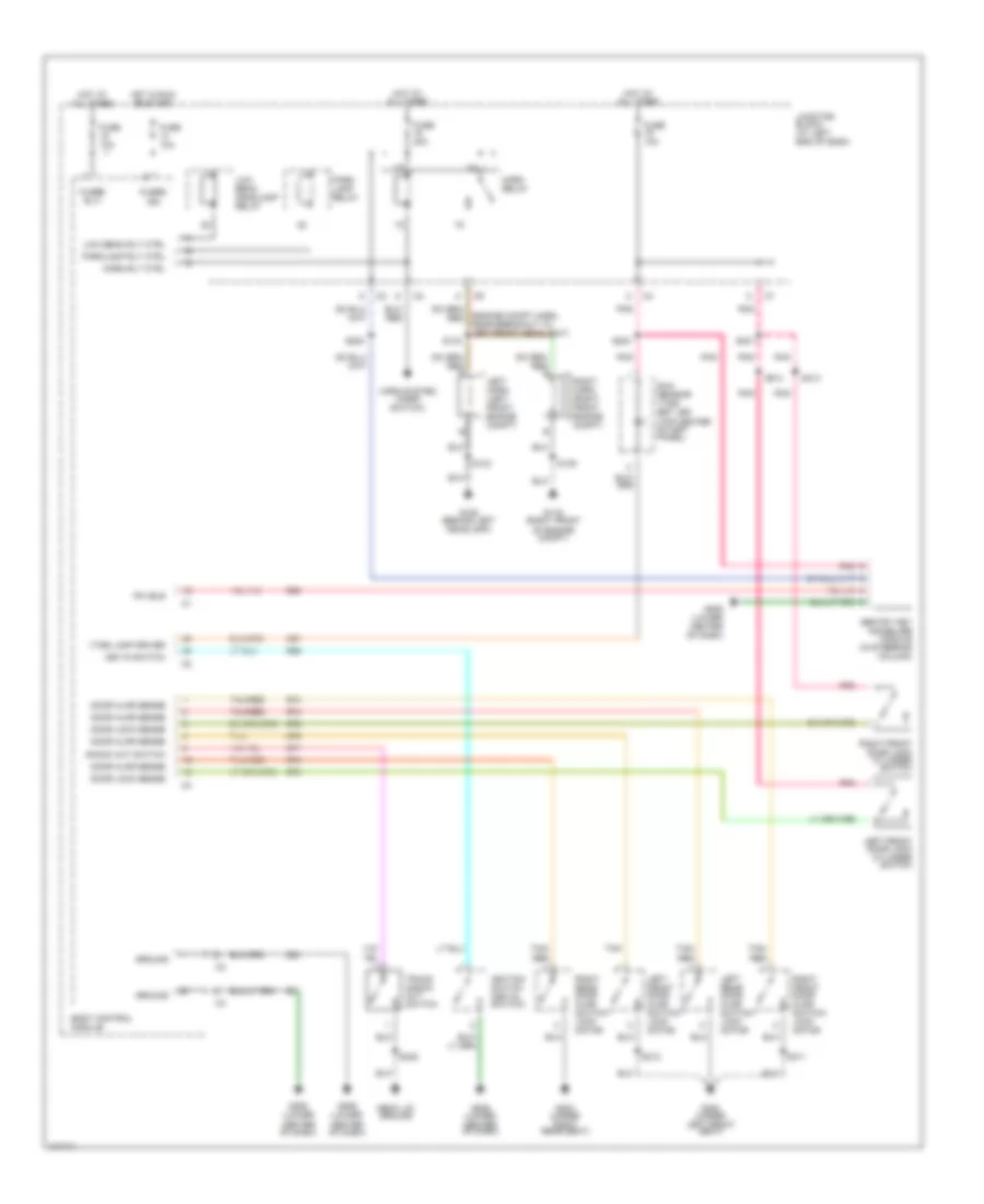
EXTERIOR LIGHTS
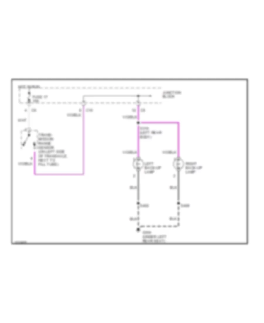
Back-up Lamps Wiring Diagram for Dodge Intrepid 1998
List of elements for Back-up Lamps Wiring Diagram for Dodge Intrepid 1998:
- C10
- Fuse 17 10a
- G304 (under left rear seat)
- Hot in run
- Junction block
- Left back-up lamp
- Right back-up lamp
- S310 (left rear body)
- S402
- S409
- Trans- mission range sensor (on left side of transaxle, next to fill tube)
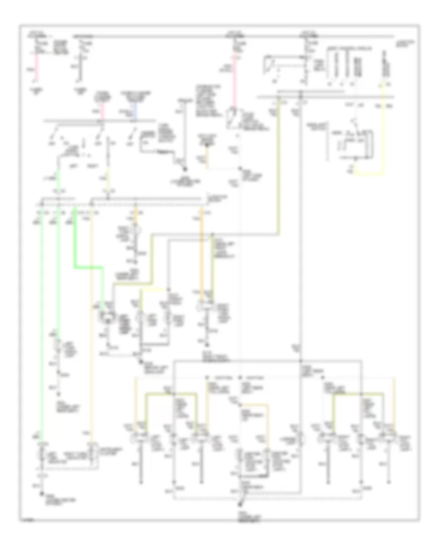
Exterior Lamps Wiring Diagram for Dodge Intrepid 1998
List of elements for Exterior Lamps Wiring Diagram for Dodge Intrepid 1998:
- Anti-lock brake system
- Auto
- Body control module
- C10
- Center high mounted stop lamp 1
- Center high mounted stop lamp 2
- Combination flasher (left side of dash, between junction block and brake pedal)
- Combo flasher output
- Combo flasher switched ground
- Fuse 10a
- Fuse 20a
- Fuse o 20a
- Fused b+
- Fused ign
- G106 (behind left headlamp)
- G119 (right front of eng compt)
- G206 (lower center of dash)
- G304 (under left rear seat)
- Ground
- Hazard switch
- Head
- Headlamp mode rtn
- Headlamp sw output
- Headlamp switch
- Hot at all times
- Hot in run
- Instrument cluster
- Junction block
- Left
- Left left park/ park/ turn turn signal signal lamp lamp
- Left park lamp
- Left tail lamp
- Left tail/ stop lamp 1
- Left tail/ stop lamp 2
- Left turn indicator
- Left turn signal lamp
- License lamp
- Off
- Park
- Park lamp relay
- Pnk
- Power distri- bution center
- Relay cntrl
- Relay output
- Right
- Right park lamp
- Right park/ turn signal lamp
- Right tail lamp
- Right tail/ stop lamp 1
- Right tail/ stop lamp 2
- Right turn indicator
- Right turn signal lamp
- S131 (near left front lamps breakout)
- S134
- S135
- S205 (left side of dash)
- S308 (left rear body)
- S309 (left rear body)
- S402
- S403 (near left tail- lamps)
- S404 (near left taillamps)
- S406 (near deck lid)
- S407 (near left tail- lamps)
- S408 (near left taillamps)
- S409
- Stop lamp switch (at top of brake pedal)
- Tan
- Turn signal switch
- Turn signal/ hazard warning switch
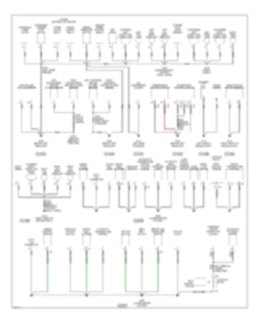
GROUND DISTRIBUTION
Ground Distribution Wiring Diagram (1 of 2) for Dodge Intrepid 1998
List of elements for Ground Distribution Wiring Diagram (1 of 2) for Dodge Intrepid 1998:
- (concorde) left park/turn signal lamp
- (concorde) right park/turn signal lamp
- (intrepid) left park/turn signal lamp
- (intrepid) right park/turn signal lamp
- A/c compressor clutch
- Airbag control module
- Analog clock
- Ash receiver lamp
- Automatic day/night mirror
- Automatic temp- erature control
- Automatic temperature control
- Automatic temperature control power module
- Battery
- Body control module
- Brake pressure switch
- C11
- Cigar lighter
- Combin- ation flasher
- Controller anti-lock brake
- Data link connector
- G101
- G102
- G103
- G104
- G105
- G106
- G106 (behind left headlamp)
- G108
- G112 (left side of engine compt)
- G114 (left rear of engine)
- G119 (right front of engine compt)
- G200
- G201
- G206 (lower center of dash)
- Glove box lamp
- Headlamp switch
- Ignition switch
- Instru- ment cluster
- Junction block
- Left downstream heated oxygen sensor
- Left fog lamp
- Left high beam headlamp
- Left horn
- Left low beam headlamp
- Left park lamp
- Left upstream heated oxygen sensor
- Manual temperature control
- Overhead travel information system
- Power distribution center
- Powertrain control module
- Prndl illum- ination
- Radiator fan motor assembly
- Right downstream heated oxygen sensor
- Right fog lamp
- Right high beam headlamp
- Right horn
- Right low beam headlamp
- Right park lamp
- Right upstream heated oxygen sensor
- S119 (left inner fender)
- S123 (ground breakout from pdc)
- S134 (near breakout for left front lamps)
- S138 (front fascia)
- S321 (premium) (under headliner)
- Seat belt switch
- Sentry key immobilizer module
- Traction control switch
- Trans- mission
- Trans- mission relay
- Transmission control module
- Turn signal/ hazard warning switch
- Vehicle speed control servo
- Washer fluid level sensor
- Windshield washer pump motor
- Windshield wiper motor
- Wiper on/off relay
- Z11
- Z12
- Z13
- Z14
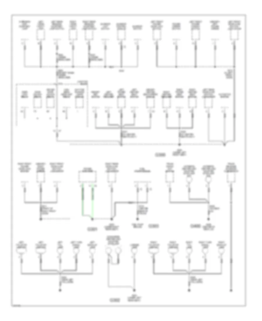
Ground Distribution Wiring Diagram (2 of 2) for Dodge Intrepid 1998
List of elements for Ground Distribution Wiring Diagram (2 of 2) for Dodge Intrepid 1998:
- (concorde) center high mounted stoplamp
- (intrepid) center high mounted stoplamp no1
- (intrepid) center high mounted stoplamp no2
- (memory) left power mirror
- (memory) right power mirror
- Autostick switch
- C11
- Daytime running lamps module
- Door lock relay
- Door unlock relay
- Driver door unlock relay
- Fuel pump ground
- Fuel pump module
- G300
- G300 (under left front seat)
- G301
- G302
- G303
- G303 (under right rear seat)
- G304 (under left rear seat)
- G400
- G406 (center of deck lid)
- High beam headlamp relay
- Junction block
- Left back-up lamp
- Left front door ajar switch/ lock motor
- Left front power door lock switch
- Left front power window switch
- Left heated recliner
- Left heated seat switch
- Left power seat switch
- Left rear door ajar switch/ lock motor
- Left rear reading courtesy lamp switch
- Left tail lamp
- Left tail/stop lamp no1
- Left tail/stop lamp no2
- Left turn signal lamp
- Left visor/ vanity lamp
- License lamp
- Memory heated seat/mirror module
- Memory set switch
- Overhead map/ courtesy lamp
- Power amplifier
- Power mirror switch
- Right back-up lamp
- Right front door ajar switch/ lock motor
- Right front power door lock switch
- Right heated recliner
- Right heated seat switch
- Right power seat switch
- Right rear door ajar switch/ lock motor
- Right rear reading courtesy lamp switch
- Right tail lamp
- Right tail/stop lamp no1
- Right tail/stop lamp no2
- Right turn signal lamp
- Right visor/ vanity lamp
- S140 (center rear of trunk)
- S312 (in left front door)
- S340
- S402 (near left taillamps)
- S405 (on deck lid)
- S409 (near left taillamps)
- Sunroof control module
- Sunroof limit switch
- Sunroof switch
- Trunk knock out switch
- Trunk release solenoid/ ajar switch
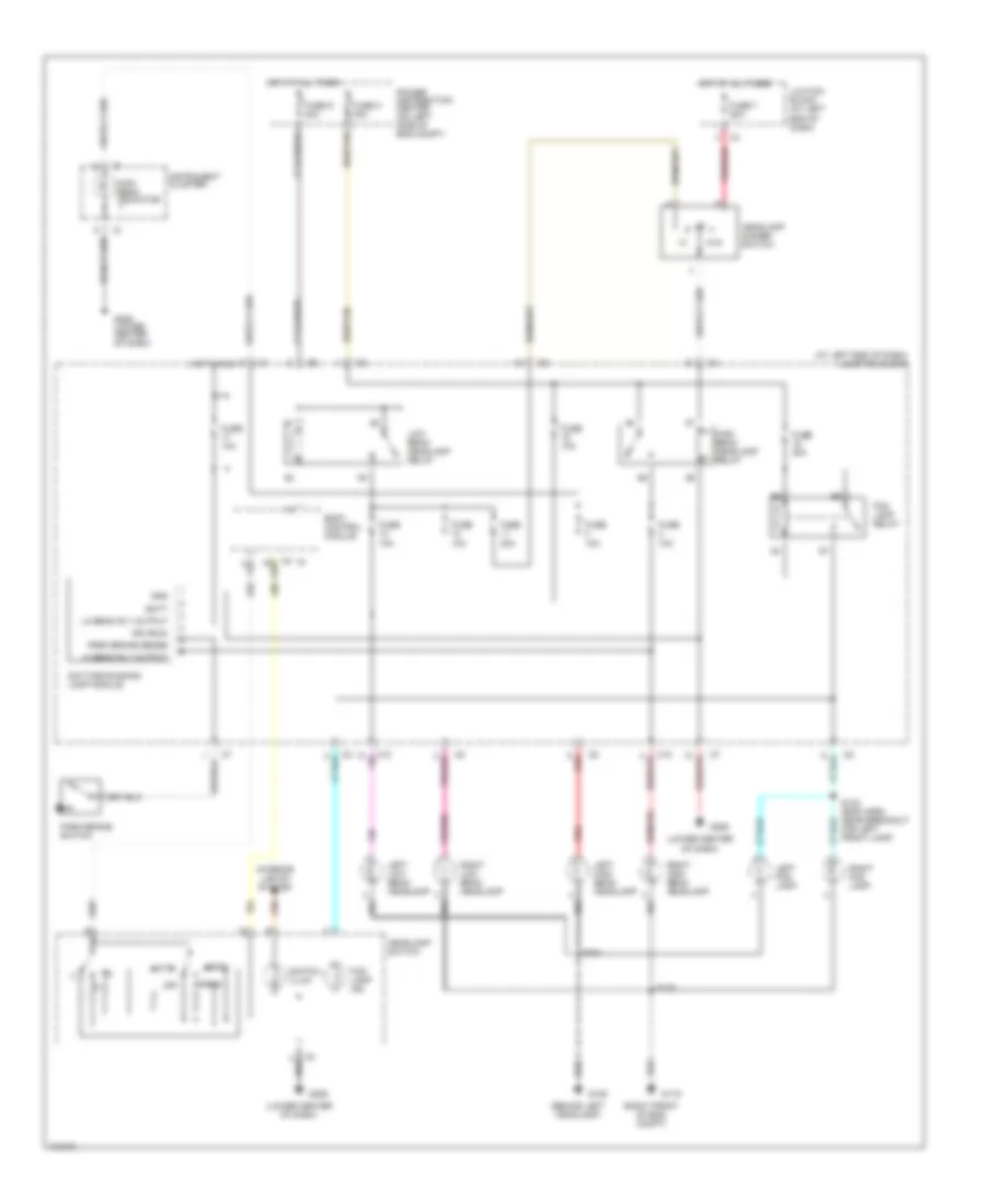
HEADLIGHTS
Headlamps/Fog Lamps Wiring Diagram, with DRL for Dodge Intrepid 1998
List of elements for Headlamps/Fog Lamps Wiring Diagram, with DRL for Dodge Intrepid 1998:
- (at left end of dash) junction block
- (behind left headlamp)
- (lower center of dash)
- (right front of eng compt)
- Auto
- Batt
- Body control module
- C10
- Daytime running lamp module
- Fog lamp ind
- Fog lamp relay
- Ftp
- Fuse 10a
- Fuse 20a
- Fuse 7 20a
- Fuse c 30a
- Fuse d 40a
- G106
- G119
- G206
- G206 (lower center of dash)
- G52
- Gnd
- Head
- Headlamp dimmer switch
- Headlamp switch
- Hi beam rly output
- High beam headlamp relay
- High beam indicator
- Hot at all times
- Hot in run
- Ign (run)
- Instrument cluster
- Interior lights system
- Juction block (at left end of dash)
- L80
- Left fog lamp
- Left high beam headlamp
- Left low beam headlamp
- Lo beam rly output
- Low beam headlamp relay
- Off
- Park
- Park brake sense
- Park brake switch
- Pnk/red
- Power distribution center (on left side of eng compt)
- Red
- Red/tan
- Right fog lamp
- Right high beam headlamp
- Right low beam headlamp
- S132 (eng harn, near breakout for left front lamp)
- S134
- S135
- Switch illum
Headlamps/Fog Lamps Wiring Diagram, without DRL for Dodge Intrepid 1998
List of elements for Headlamps/Fog Lamps Wiring Diagram, without DRL for Dodge Intrepid 1998:
- (at left end of dash) junction block
- (behind left headlamp)
- (lower center of dash)
- (right front of eng compt)
- Auto
- Body control module
- C10
- Fog lamp ind
- Fog lamp relay
- Ftp
- Fuse 10a
- Fuse 20a
- Fuse 7 20a
- Fuse c 30a
- Fuse d 40a
- G106
- G119
- G206
- G206 (lower center of dash)
- G52
- Head
- Headlamp dimmer switch
- Headlamp switch
- High beam headlamp relay
- High beam indicator
- Hot at all times
- Instrument cluster
- Interior lights system
- Juction block (at left end of dash)
- L80
- Left fog lamp
- Left high beam headlamp
- Left low beam headlamp
- Low beam headlamp relay
- Off
- Park
- Pnk/red
- Power distribution center (on left side of eng compt)
- Red
- Red/tan
- Right fog lamp
- Right high beam headlamp
- Right low beam headlamp
- S132 (eng harn, near breakout for left front lamp)
- S134
- S135
- Switch illum
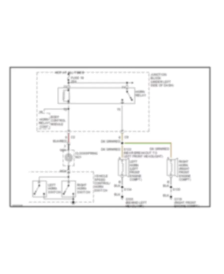
HORN
Horn Wiring Diagram for Dodge Intrepid 1998
List of elements for Horn Wiring Diagram for Dodge Intrepid 1998:
- (near breakout to left front headlight) a
- Body control module
- Clockspring no1
- Fuse 18 20a
- G106 (behind left headlamp)
- G119 (right front engine compt)
- Horn relay
- Horn relay cont
- Hot at all times
- Junction block (under left side of dash)
- Left horn (left front engine compt)
- Left horn switch
- Nca
- Right horn (right front engine compt)
- Right horn switch
- S134
- S135
- Vehicle speed control/ horn switch
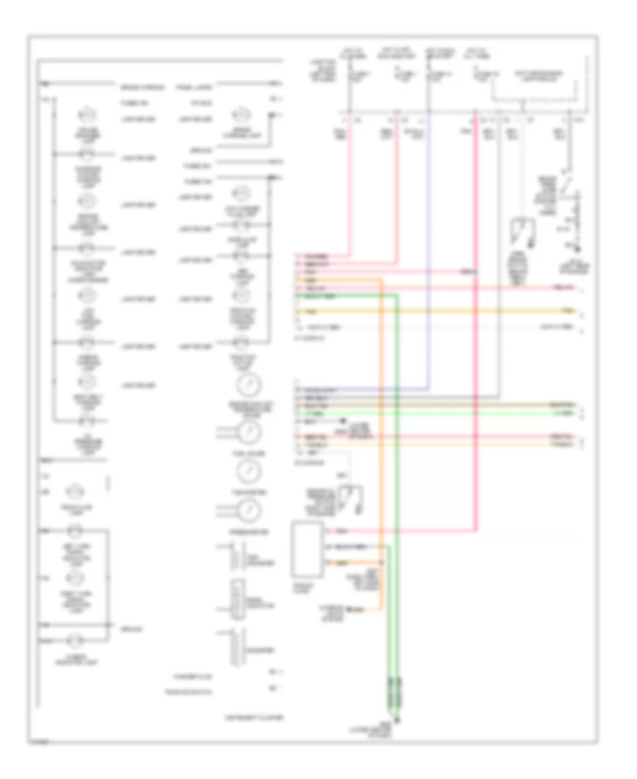
INSTRUMENT CLUSTER
Instrument Cluster Wiring Diagram (1 of 2) for Dodge Intrepid 1998
List of elements for Instrument Cluster Wiring Diagram (1 of 2) for Dodge Intrepid 1998:
- (left rear of engine)
- (lower center of dash)
- A10
- Abs warning lamp
- Airbag warning lamp
- Analog clock
- B10
- Brake pres- sure switch (master cyl- inder)
- Brake warning
- Brake warning lamp
- C1 (conn a)
- C10
- C2 (conn b)
- Charging system warning lamp
- Cruise engaged lamp
- Daytime running lamp module
- Door ajar lamp
- Engine coolant temperature gauge
- Engine coolant temperature lamp
- Engine oil pressure switch (right side of engine)
- Fuel gauge
- Fuse 1 10a
- Fuse 14 10a
- Fuse 19 10a
- Fuse 7 20a
- Fused (b+)
- Fused ign
- G114
- G206
- G206 (lower center of dash)
- Ground
- Hi beam indicator lamp
- Hot at all times
- Hot in off, run or start
- Hot in run or start
- Instrument cluster
- Interior lights system
- Junction block (left end of dash)
- Lamp driver
- Left turn signal indicator lamp
- Low fuel warning lamp
- Low washer fluid lamp
- Malfunction indicator lamp (check engine)
- Odometer
- Oil pressure warning lamp
- P r n d l
- Panel lamps
- Park brake switch (brake pedal assy)
- Pci bus
- Pnk
- Pnk/ red
- Pnk/red
- Prndl indicator
- Right turn signal indicator lamp
- S119
- S204
- S207 (dash harn, left side of dash)
- Seat belt warning lamp
- Speedometer
- Tachometer
- Tan
- Traction active lamp
- Traction control warning lamp
- Traction switch
- Trip odometer
- Trunk ajar lamp
- Washer fluid
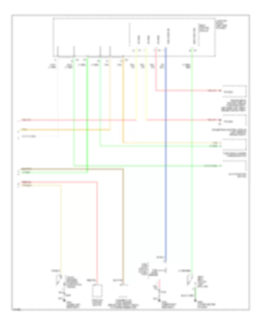
Instrument Cluster Wiring Diagram (2 of 2) for Dodge Intrepid 1998
List of elements for Instrument Cluster Wiring Diagram (2 of 2) for Dodge Intrepid 1998:
- Body control module
- Fuel level in
- Fuel level sensor
- Fuel pump module (in fuel tank)
- G206 (lower center of dash)
- G303 (under right rear seat)
- G304 (under left rear seat)
- Junction block (left end of dash)
- Multi-function switch
- Pci bus
- Powertrain control module (left rear of engine compt)
- S140
- S405
- Seat belt sw
- Seat belt switch (left b-pillar)
- Tan
- Traction control switch
- Transmission control module (in engine compt, between left front fender and battery)
- Trunk release solenoid/ ajar switch (trunk)
- Turn signal/hazard warning switch
- Washer fluid level sensor (behind left front fascia, in washer reservoir)
INTERIOR LIGHTS
Interior Light Wiring Diagram for Dodge Intrepid 1998
List of elements for Interior Light Wiring Diagram for Dodge Intrepid 1998:
- (body harn, under head- liner) s319
- (body harn, under head- liner) s320
- (lower center of dash) g206
- Analog clock
- Ash receiver lamp
- Auto a/c
- Automatic temperature control
- Base
- Body control module
- C11
- Fuse 19 10a
- G206 (lower center of dash)
- G300 (under left front seat)
- G303 (under right front seat)
- G304 (under left rear seat)
- Glove box lamp
- Headlamp switch
- Hot at all times
- Instrument cluster
- Instrument cluster system
- Interior lamps dimming signal
- Junction block (at left end of dash)
- Left front door ajar switch/lock motor assy (left frt door)
- Left front door courtesy lamp
- Left rear door ajar switch/lock motor assy (left rr door)
- Left rear door courtesy lamp
- Left rear reading/ courtesy lamp
- Left rear reading/ courtesy lamp switch
- Left visor/ vanity lamp
- Manual a/c
- Manual temperature control
- Other
- Overhead map/ courtesy lamp
- Pnk
- Power mirror switch
- Prndl illumination lamp
- Radio
- Red
- Right front door ajar switch/lock motor assy (right frt door)
- Right front door courtesy lamp
- Right rear door ajar switch/lock motor assy (right rr door)
- Right rear door courtesy lamp
- Right rear reading/ courtesy lamp
- Right rear reading/ courtesy lamp switch
- Right visor/ vanity lamp
- S207 (body harn, left side of dash)
- S301 (body harn, left front sill)
- S302 (body harn, left front sill)
- S307 (body harn, left rear body)
- S311
- S312
- S314 (body harn, left front door)
- S323 (body harn, under headliner)
- S325
- S327
- S329 (body harn, left side body)
- S405
- Tan
- Tan/red
- Traction control switch
- Trunk lamp
- Trunk release solenoid/ ajar switch (trunk latch)
POWER DISTRIBUTION
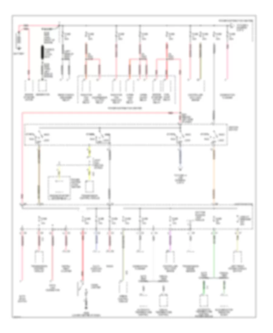
Power Distribution Wiring Diagram (1 of 3) for Dodge Intrepid 1998
List of elements for Power Distribution Wiring Diagram (1 of 3) for Dodge Intrepid 1998:
- (in pdc) s124
- (in pdc) s125
- (in pdc) s128
- (left rear of body) s306
- A/c compressor clutch relay
- A41
- Acc
- Airbag control module
- Auto temp control
- Auto- stick switch
- Automatic temperature control
- Automatic temperature control power module
- Battery
- Blower motor resistor block
- Cigar lighter
- Circuit breaker no1 20a
- Combination flasher
- Controller anti-lock brake
- Data link connector
- Daytime running lamp module
- Engine starter motor
- Engine starter motor relay
- F11
- F23
- Fuel pump relay
- Fuse 10a
- Fuse 15a
- Fuse 30a
- Fuse a 50a
- Fuse b 30a
- Fuse e 40a
- Fuse g 40a
- Fuse h 30a
- Fuse j 40a
- Fuse k 40a
- Fuse m 40a
- Fuse o 20a
- G206 (lower center of dash)
- Generator
- Ignition switch
- Instru- ment cluster
- Joint con- nector (in pdc)
- Junction block
- Left front power window switch
- Lock
- Manual temp control
- Manual temperature control
- Multi- function switch
- Of dash)
- Off
- Pnk
- Power distrib- ution center
- Power distribution center
- Radiator fan high relay
- Radiator fan high/low relay
- Radio
- Rear window defogger relay
- Red
- Relay
- Run
- S106 (eng harn, front of engine)
- S109 (eng harn, left side of engine)
- S201 (behind left side red
- Start
- Tan
- To fuse 14 (j/b) (diagram 2 of 3)
- To fuse c (diagram 2 of 3)
- Transmission control module
- Transmission range sensor
- Wiper high/ low relay
- Wiper on/off relay
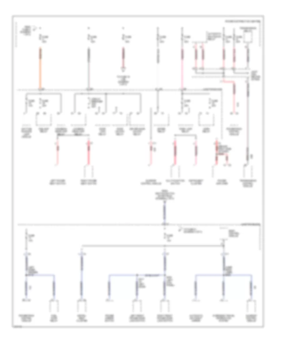
Power Distribution Wiring Diagram (2 of 3) for Dodge Intrepid 1998
List of elements for Power Distribution Wiring Diagram (2 of 3) for Dodge Intrepid 1998:
- (behind red
- (diagram 1 of 3)
- (left inner fender) s116
- (uner head- liner) s322
- A14
- A30
- A37
- Automatic day/night mirror
- Automatic shutdown relay
- Body control module
- C11
- Circuit breaker no2 20a
- Daytime running lamp module
- Door lock relay
- Door unlock relay
- Driver door unlock relay
- F12
- Foglamp relay
- From fuse o a
- From ignition switch (start/run) (diagram 1 of 3)
- Fuel pump relay
- Fuse 10a
- Fuse 20a
- Fuse c 30a
- Fuse d 40a
- Fuse f 20a
- Fuse i 30a
- Fuse l 40a
- Fuse n 30a
- Fuse q 20a
- Highbeam headlamp relay
- Horn relay
- Instru- ment cluster
- Instrument cluster
- Joint con- nector (in pdc)
- Junction block
- Left front power door lock switch
- Left power seat switch
- Lowbeam headlamp relay
- Multi-function switch
- Overhead travel information system
- Park lamp relay
- Pnk/red
- Power amplifier
- Power distribution center
- Power mirror switch
- Powertrain control module
- Red
- Red/tan
- Right front power door lock switch
- Right power seat switch
- Right side of dash) s209
- S300 (left kick panel)
- S317 (in left door)
- Spare relay
- Sunroof control module
- To fuse 19 (j/b) (diagram 3 of 3)
- To fuse 21 (diagram 3 of 3)
- Transmission control module
- Transmission relay
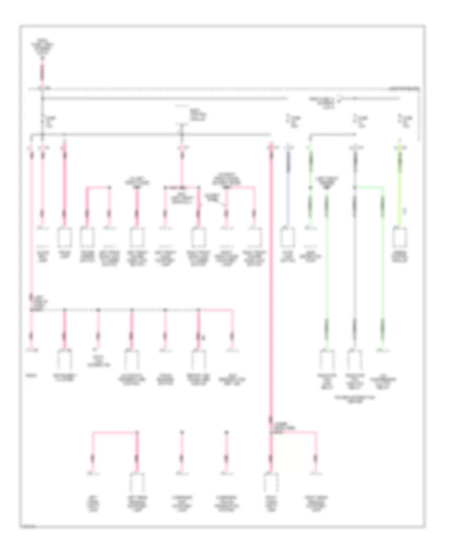
Power Distribution Wiring Diagram (3 of 3) for Dodge Intrepid 1998
List of elements for Power Distribution Wiring Diagram (3 of 3) for Dodge Intrepid 1998:
- (in left front door) s314
- (in right front door) (except base) s313
- (left front fender) s117
- (left side of pnk
- (under pnk
- A/c compressor clutch relay
- Airbag control module
- Automatic temperature control
- Body control module
- C10
- C11
- Dash) s204
- Data link connector
- Except base
- F14
- From fuse 14 d (diagram 2 of 3)
- From fuse i (pdc) (diagram 2 of 3)
- Fuse 10a
- Fuse 20a
- Glove box lamp
- Headliner) s319
- Instrument cluster
- Junction block
- Leak detection pump
- Left front door courtesy lamp
- Left front door lock cylinder switch
- Left front power door lock switch
- Left rear reading courtesy lamp
- Left visor/ vanity lamp
- Overhead map/ courtesy lamp
- Overhead travel information system
- Pnk
- Power distribution center
- Power mirror switch
- Radiator fan high relay
- Radiator fan high/low relay
- Radio
- Right front door courtesy lamp
- Right front door lock cylinder switch
- Right front power door lock switch
- Right rear reading courtesy lamp
- Right visor/ vanity lamp
- S301 (left front door sill)
- Sentry key immobilizer module
- Stop lamp switch
- Sun sensor/vtss set led
- Trunk lamp
- Trunk release switch
POWER DOOR LOCKS
Power Door Lock Wiring Diagram for Dodge Intrepid 1998
List of elements for Power Door Lock Wiring Diagram for Dodge Intrepid 1998:
- (body harn, left rear body)
- (body harn, near fuel pump module) s303
- Body control module
- Circuit breaker 2 20a
- Door ajar sw sense
- Door lock relay
- Door lock relay control
- Door unlock relay
- Door unlock relay control
- Driver door unlock relay
- Fuse 10a
- G300 (under left front seat)
- G303 (under right rear seat)
- G406 (center of deck lid)
- Hot at all times
- Hot in start or run
- Junction block
- Left front door ajar switch/ lock motor
- Left front power door lock switch
- Left lock/ unlock sense
- Left rear door ajar switch/ lock motor
- Left unlock relay control
- Pnk
- Right front door ajar switch/ lock motor
- Right front power door lock switch
- Right rear door ajar switch/ lock motor
- S204
- S300
- S301
- S304
- S311
- S312
- S313 (w/ courtesy lamps)
- S317
- Seats)
- Tan
- Tan/ red
- Trunk release solenoid
- Trunk release solenoid/ ajar switch
- Trunk release switch
POWER MIRRORS
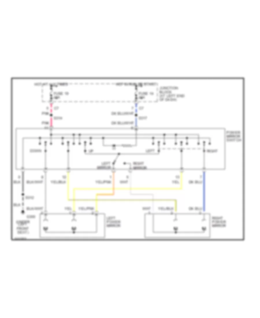
Power Mirror Wiring Diagram for Dodge Intrepid 1998
List of elements for Power Mirror Wiring Diagram for Dodge Intrepid 1998:
- (under left front seat)
- Down
- Fuse 14 10a
- Fuse 19 10a
- G300
- Hot at all times
- Hot in run or start
- Junction block (at left end of dash)
- Left
- Left mirror
- Left power mirror
- Pnk
- Power mirror switch
- Right
- Right mirror
- Right power mirror
- S312
- S314
- S317
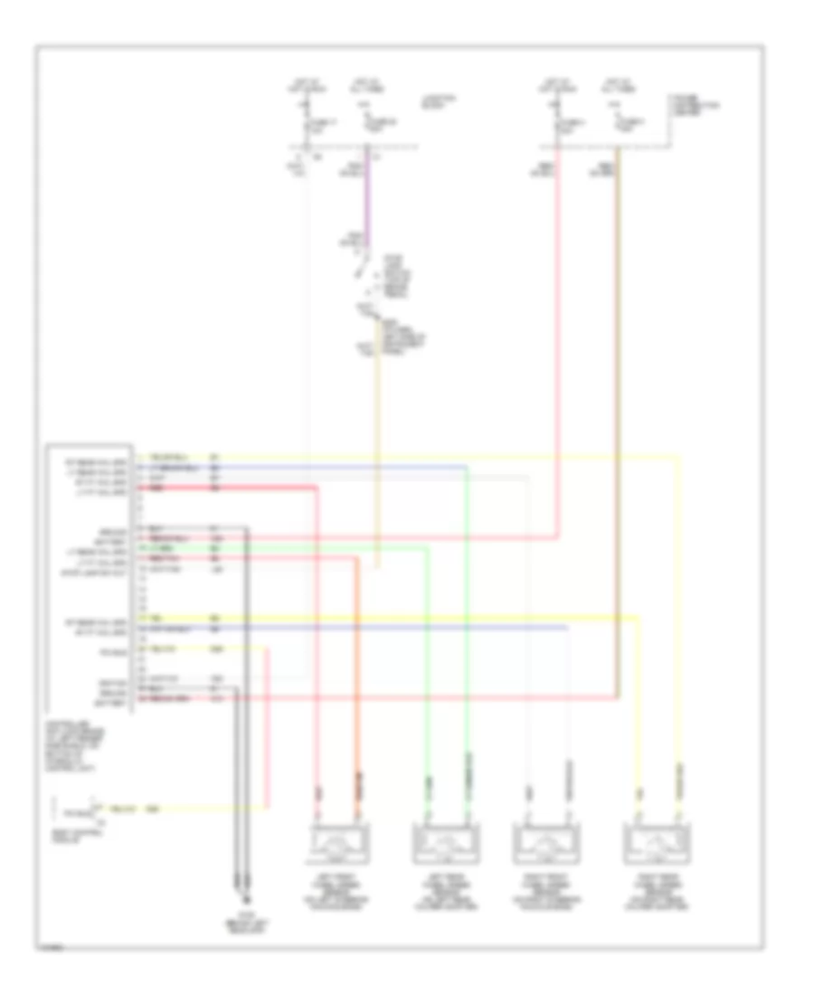
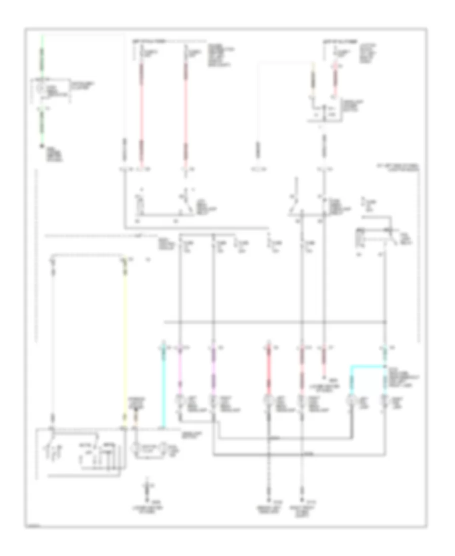
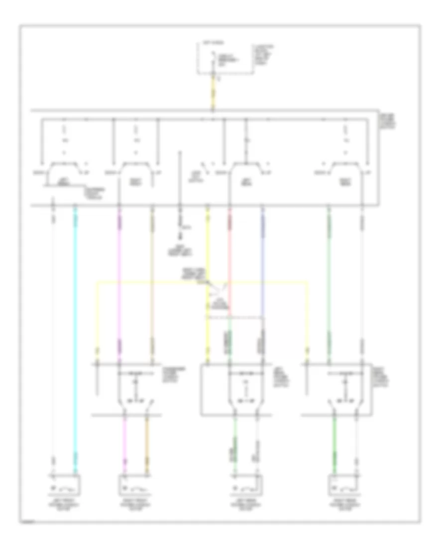
POWER SEATS
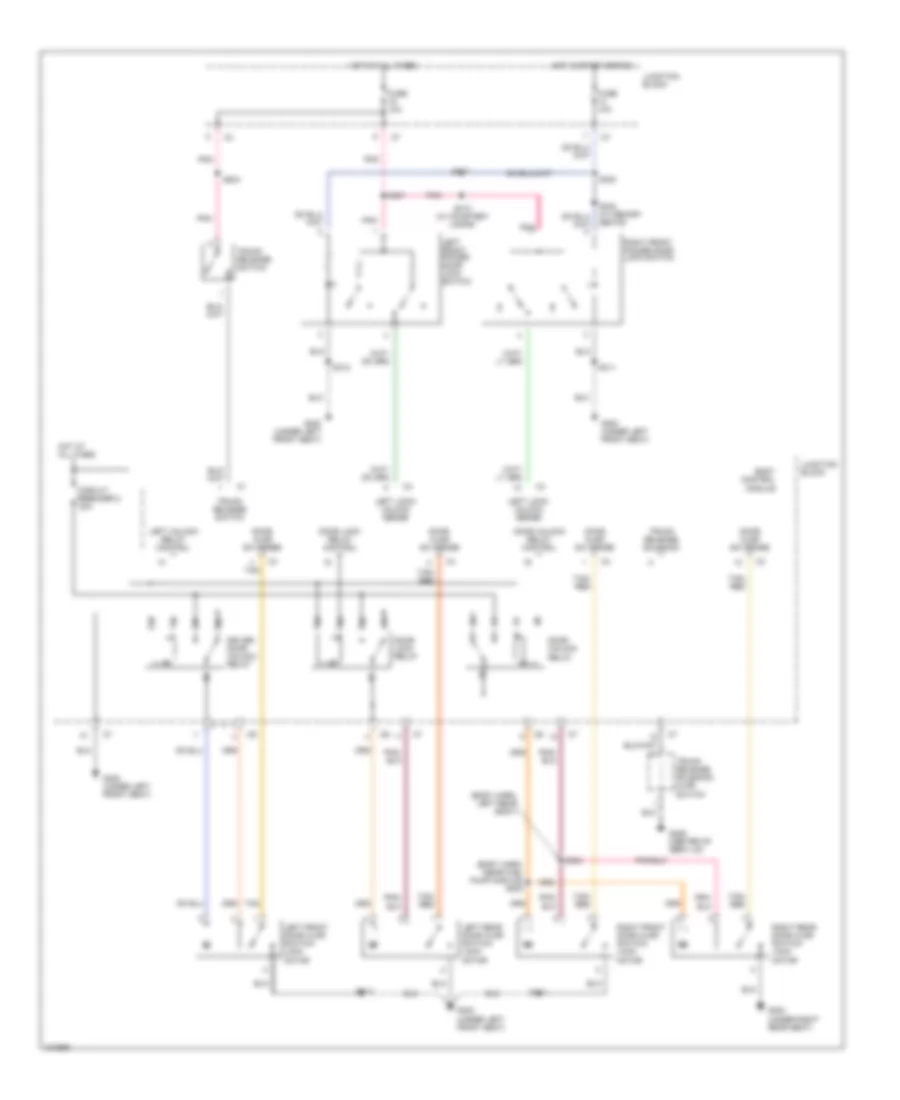
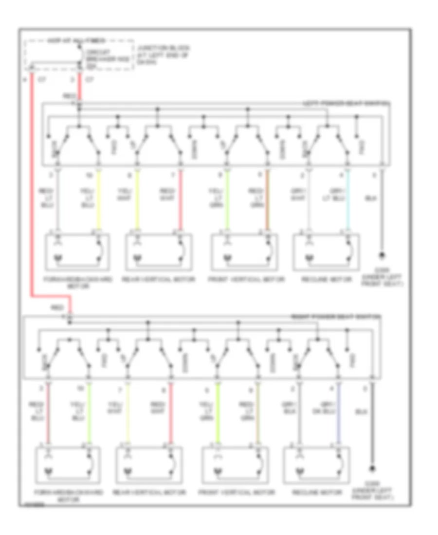
Power Seat Wiring Diagrams for Dodge Intrepid 1998
List of elements for Power Seat Wiring Diagrams for Dodge Intrepid 1998:
- Back
- Circuit breaker no2 20a
- Down
- Forward/backward motor
- Front vertical motor
- Fwd
- G300 (under left front seat)
- Hot at all times
- Junction block (at left end of dash)
- Left power seat switch
- Rear vertical motor
- Recline motor
- Red
- Right power seat switch
POWER TOP/SUNROOF
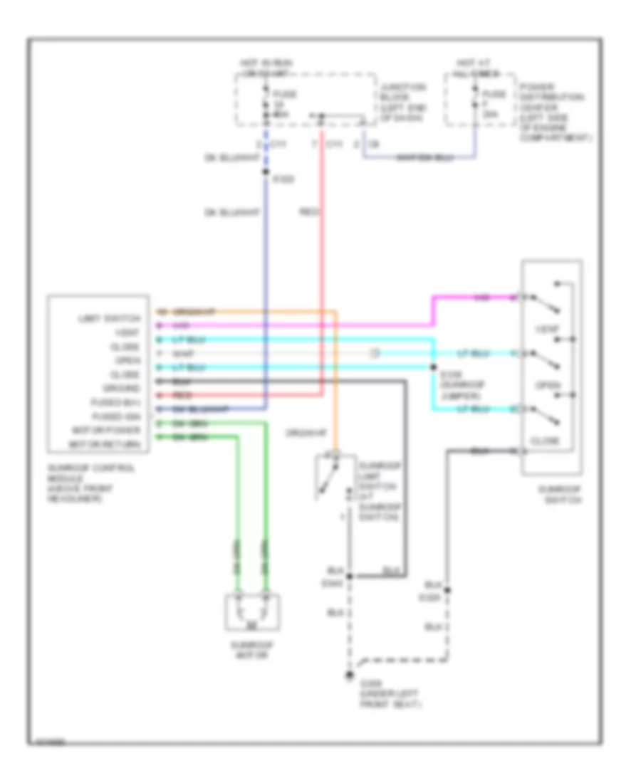
Power Top/Sunroof Wiring Diagrams for Dodge Intrepid 1998
List of elements for Power Top/Sunroof Wiring Diagrams for Dodge Intrepid 1998:
- C11
- Close
- Fuse 10a
- Fuse f 20a
- Fused b(+)
- Fused ign
- G300 (under left front seat)
- Ground
- Hot at all times
- Hot in run or start
- Junction block (left end of dash)
- Limit switch
- Motor power
- Motor return
- Open
- Power distribution center (left side of engine compartment)
- Red
- S320
- S322
- S339 (sunroof jumper)
- S340
- Sunroof control module (above front headliner)
- Sunroof limit switch (at sunroof switch)
- Sunroof motor
- Sunroof switch
- Vent
POWER WINDOWS
Power Window Wiring Diagram for Dodge Intrepid 1998
List of elements for Power Window Wiring Diagram for Dodge Intrepid 1998:
- (body harn, under left front seat) s305
- Circuit breaker 1 20a
- Down
- Driver power window switch
- Express down module
- G300 (under left front seat)
- Hot in run
- Junction block (at left end of dash)
- Left front
- Left front power window motor
- Left rear
- Left rear power window motor
- Left rear power window switch
- Lock out switch
- Passenger power window switch
- Right front
- Right front power window motor
- Right rear
- Right rear power window motor
- Right rear power window switch
- S312
- Tan
- W/0 police package
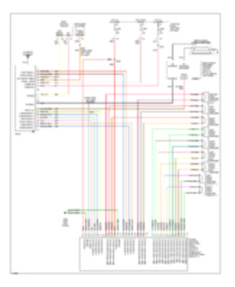
RADIO
Radio Wiring Diagrams, with Amplifier for Dodge Intrepid 1998
List of elements for Radio Wiring Diagrams, with Amplifier for Dodge Intrepid 1998:
- (dash harn, left side of dash)
- (intrepid) antenna
- Am antenna
- Amp center dash spkr (+)
- Amp center dash spkr (-)
- Amp l door sail spkr (+)
- Amp l door sail spkr (-)
- Amp l frnt door spkr (+)
- Amp l frnt door spkr (-)
- Amp l rear door spkr (+)
- Amp l rear door spkr (-)
- Amp l rear shelf spkr (+)
- Amp l rear shelf spkr (-)
- Amp r door sail spkr (+)
- Amp r door sail spkr (-)
- Amp r frnt door spkr (+)
- Amp r frnt door spkr (-)
- Amp r rear door spkr (+)
- Amp r rear door spkr (-)
- Amp r rear shelf spkr (+)
- Amp r rear shelf spkr (-)
- Antenna
- Body control module
- Center dash speaker (infinity i & ii)
- D25
- Day bright sens
- Day bright sense
- E17
- Fm antenna/ defogger
- Fuse 10a
- Fuse 20a
- Fused b(+)
- Fused ign
- G200 (left kick panel)
- Ground
- Hot at all times
- Hot in run or acc
- Instrument cluster
- Junction block (left end of dash)
- L frnt spkr (+)
- L frnt spkr (-)
- L front spkr (+)
- L front spkr (-)
- L rear spkr (+)
- L rear spkr (-)
- Left front door sail speaker
- Left front door speaker
- Left rear door speaker (infinity ii)
- Left rear shelf speaker
- Nca
- Panel lamps
- Panel lamps driver
- Pci bus
- Pnk
- Pnk/red
- Power amplifier (right kick panel) (midline & infinity i) (inner right quarter panel) (infinity ii)
- R frnt spkr (+)
- R frnt spkr (-)
- R front spkr (+)
- R front spkr (-)
- R rear spkr (+)
- R rear spkr (-)
- Radio
- Radio 12 volt output
- Radio 12v
- Rear window antenna/defogger
- Rear window defogger/ antenna module (right "c" pillar, behind trim panel)
- Red
- Right front door sail speaker
- Right front door speaker
- Right rear door speaker (infinity ii)
- Right rear shelf speaker
- S204
- S206
- S207 (dash harn, left side of dash)
- S209
- Tan/red
- X12
- X51
- X52
- X53
- X54
- X55
- X56
- X57
- X58
- X60
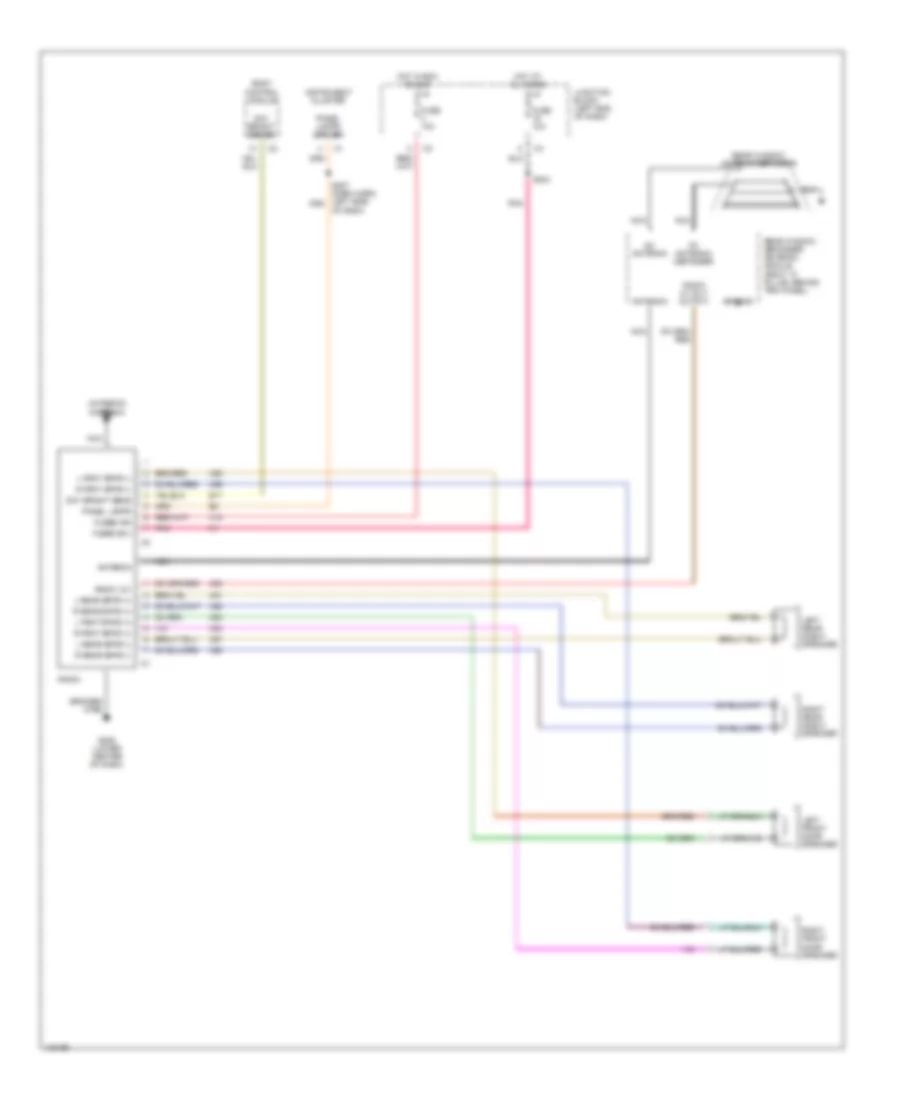
Radio Wiring Diagrams, without Amplifier for Dodge Intrepid 1998
List of elements for Radio Wiring Diagrams, without Amplifier for Dodge Intrepid 1998:
- (intrepid) antenna
- Am antenna
- Antenna
- Body control module
- Braided wire
- Day bright sens
- Day bright sense
- E17
- Fm antenna/ defogger
- Fuse 10a
- Fused b(+)
- Fused ign
- G206 (lower center of dash)
- Ground
- Hot at all times
- Hot in run or acc
- Instrument cluster
- Junction block (left end of dash)
- L frnt spkr (+)
- L frnt spkr (-)
- L rear spkr (+)
- L rear spkr (-)
- Left front door speaker
- Left rear shelf speaker
- Nca
- Of dash)
- Panel lamps
- Panel lamps driver
- Pnk
- R frnt spkr (+)
- R frnt spkr (-)
- R rear spkr (+)
- R rear spkr (-)
- Radio
- Radio 12 volt output
- Radio 12v
- Rear window antenna/defogger
- Rear window defogger/ antenna module (right "c" pillar, behind trim panel)
- Right front door speaker
- Right rear shelf speaker
- S204
- X12
- X51
- X52
- X53
- X54
- X55
- X56
- X57
- X58
- X60
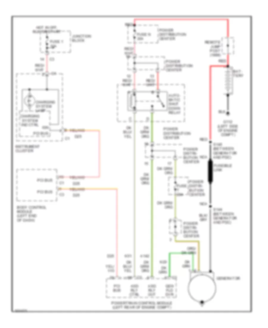
STARTING/CHARGING
Charging Wiring Diagram for Dodge Intrepid 1998
List of elements for Charging Wiring Diagram for Dodge Intrepid 1998:
- A142
- Asd rly ctrl
- Asd rly out
- Auto- matic shut down relay
- Bat- tery
- Body control module (left end of dash)
- Charging system ind ctrl
- Charging system lamp
- D25
- Fuse 1 10a
- Fuse n 30a
- Fuse t 20a
- Fuseible link
- G112 (left side of engine compt)
- Gen fld dvr
- Generator
- Hot in off, run or start
- Ign
- Instrument cluster
- Junction block
- K20
- K51
- Nca
- Pci bus
- Power distri- bution center
- Power distribution center
- Powertrain control module (left rear of engine compt)
- Red
- Remote jump post (1999)
- S144 (between generator and pdc)
- S145 (between generator and pdc)
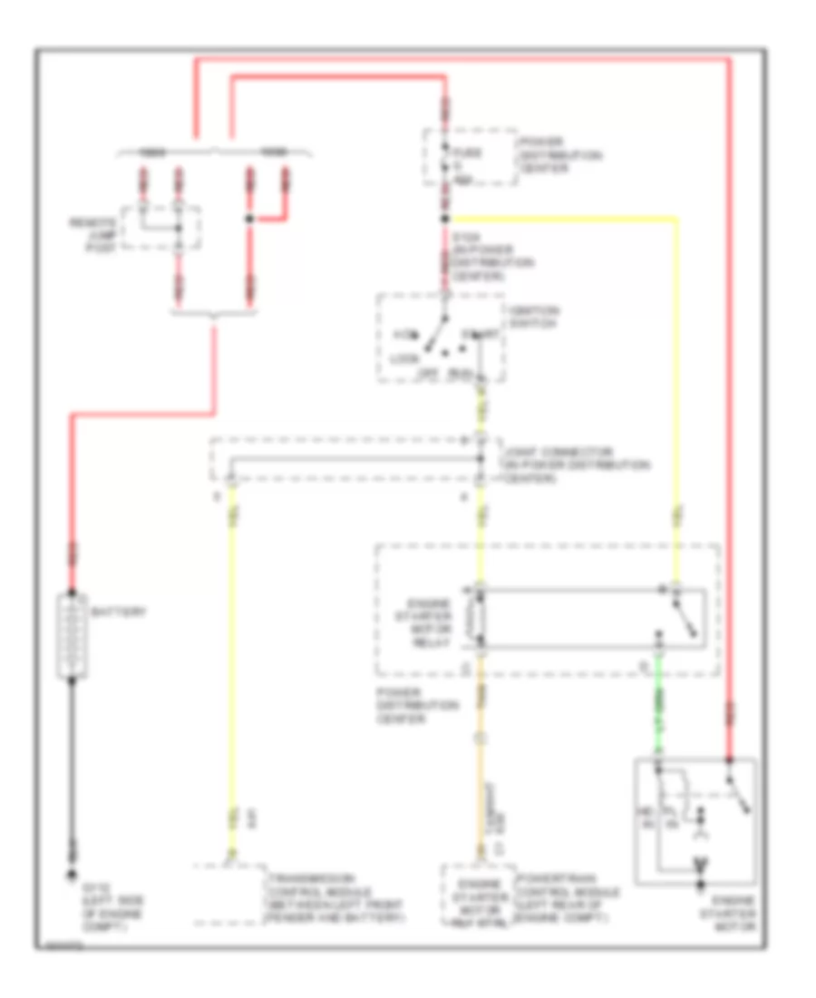
Starting Wiring Diagram for Dodge Intrepid 1998
List of elements for Starting Wiring Diagram for Dodge Intrepid 1998:
- A41
- Acc
- Battery
- Engine starter motor
- Engine starter motor relay
- Engine starter motor rly ctrl
- Fuse g 40a
- G112 (left side of engine compt)
- Hd in
- Ignition switch
- Joint connector (in power distribution center)
- K90
- Lock
- Off
- Pl in
- Power distribution center
- Powertrain control module (left rear of engine compt)
- Red
- Remote jump post
- Run
- S124 (in power distribution center) red
- Start
- Tan
- Transmission control module (between left front fender and battery)
SUPPLEMENTAL RESTRAINTS
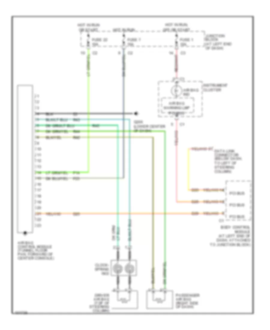
Supplemental Restraint Wiring Diagram for Dodge Intrepid 1998
List of elements for Supplemental Restraint Wiring Diagram for Dodge Intrepid 1998:
- Air bag control module (tunnel floor pan, forward of center console)
- Air bag ind
- Air bag warning lmp
- Body control module (at left end of dash, attached to junction block)
- Clock- spring no2
- D25
- Data link connector (below dash, to left of steering column)
- Driver air bag (top of steering column)
- F14
- F23
- Fuse 1 10a
- Fuse 22 10a
- Fuse 7 10a
- G206 (lower center of dash)
- Hot in run
- Hot in run,
- Instrument cluster
- Junction block (at left end of dash)
- Nca
- Off or start
- Or start
- Passenger air bag (right side of dash)
- Pci bus
- R42
- R43
- R44
- R45
TRANSMISSION
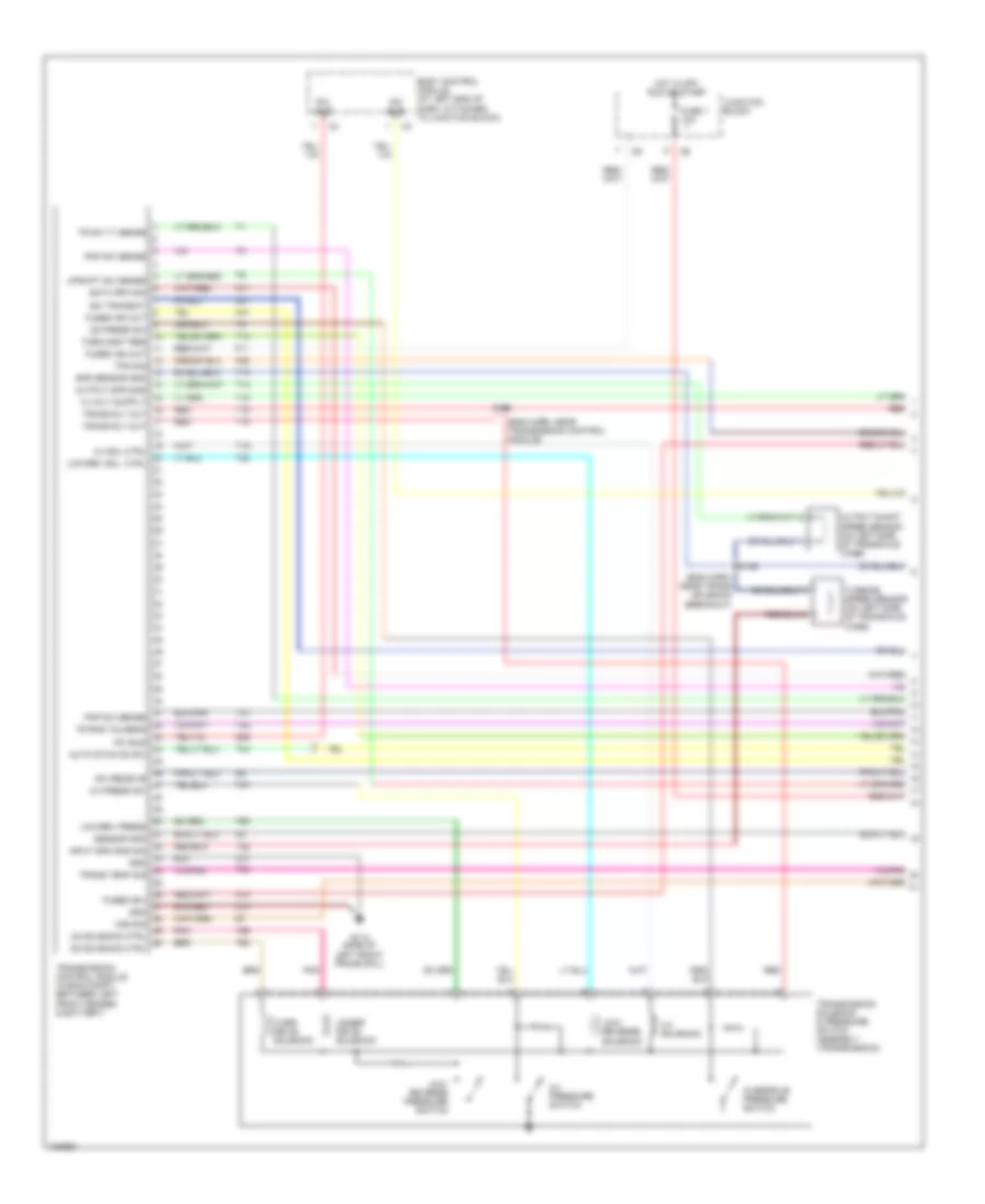
Transmission Wiring Diagram (1 of 3) for Dodge Intrepid 1998
List of elements for Transmission Wiring Diagram (1 of 3) for Dodge Intrepid 1998:
- (eng harn, near trans solenoid breakout)
- (eng harn, near transmission control module)
- 2-4 press sw
- 2-4 pressure switch
- 2-4 sol ctrl
- 2-4 solenoid
- A14
- A41
- Auto stick dn sw
- Body control module (at left end of dash, attached to junction block)
- D21
- D25
- Eatx rpm sig
- F11
- Fuse 1 10a
- Fused (b+)
- Fused ign out
- G113 (side of left front frame rail)
- Gnd
- Hot in off, run or start
- Input spd sns sig
- Junction block
- K22
- K71
- Low/ reverse pressure switch
- Low/ reverse solenoid
- Low/rev press
- Low/rev sol. ctrl
- Od press sw
- Od solenoid ctrl
- Output shaft speed sensor (on left side of transaxle case)
- Output spd sns
- Over- drive solenoid
- Overdrive pressure switch
- Pci bus
- Pnk
- Pnp sw sense
- Red
- S114
- S146
- Sci receive
- Sci transmit
- Sensor gnd
- Spd sensor gnd
- T10
- T13
- T14
- T15
- T16
- T19
- T20
- T41
- T42
- T44
- T47
- T50
- T52
- T54
- T59
- T60
- Torq mgmt req
- Tps sig
- Tr rng t42 sens
- Tr sw t1 sense
- Trans rly out
- Trans temp sig
- Transmission control module (in eng compt, between left front fender & battery)
- Transmission solenoid & pressure switch assembly (transmission)
- Turbine speed sensor (on left side of transaxle case)
- Ud solenoid ctrl
- Under- drive solenoid
- Upshift sw sense
- Vss sig
- Z13
- Z14
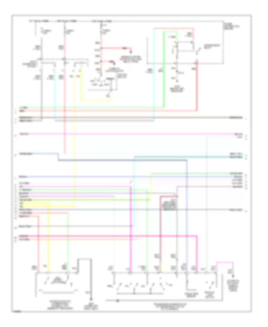
Transmission Wiring Diagram (2 of 3) for Dodge Intrepid 1998
List of elements for Transmission Wiring Diagram (2 of 3) for Dodge Intrepid 1998:
- Acc
- Automatic day/night mirror & backup lights
- Autostick switch (intrepid/300m) (integral with gearshift mechanism)
- Back-up lamp switch
- Engine starter motor & fuel pump relay in pdc
- Fuse 6 in junction block
- Fuse g 40a
- Fuse n 30a
- Fuse q 20a
- G106 (behind left headlamp)
- G300 (under left front seat)
- Hall effect switches
- Hot at all times
- Ignition switch
- Joint connector (in pdc)
- Lock
- Nol
- Off
- P3l
- Power distribution center
- Prnl
- Red
- Run
- S113 (eng harn, near speed proportion breakout)
- S119
- S124
- S201
- Start
- Trans temp sensor
- Transmission range switch (in transmission, on top of valve body)
- Transmission relay
Transmission Wiring Diagram (3 of 3) for Dodge Intrepid 1998
List of elements for Transmission Wiring Diagram (3 of 3) for Dodge Intrepid 1998:
- (behind left headlamp) g106
- (below dash, to left of steering column)
- (eng harn, left inner fender)
- (eng harn, near pcm breakout) s107
- (eng harn, near transmission control module)
- 2.7l
- 3.2l/3.5l
- A14
- Air conditioning & engine controls system
- D21
- D25
- Data link connector
- Eatm rpm sig
- Ect sensor sig
- Engine controls system
- Engine coolant temperature sensor (in water jacket, near thermostat housing)
- F12
- Fuel pump relay, controller anti-lock brake
- Fuse 10a
- Fused b (+)
- G206 (lower center of dash)
- Gnd
- Hot in run
- Hot in run & start
- Ign (run/start)
- Junction block
- K22
- K29
- K71
- P/n sw sense
- Pci bus
- Pnk
- Powertrain control module (in left rear of eng compt)
- S104 (eng harn, front of eng)
- S106 (eng harn, front of eng)
- S110 (eng harn, right side of eng)
- S115
- S116
- S118
- S127 (eng harn, in pdc)
- Sci transmit
- Sensor gnd
- Stop lamp switch (at top of brake pedal)
- Stop lp sw sense
- T10
- T41
- Throttle position sensor (on throttle body)
- Torque req sense
- Tp sens sig
- Vss signal
- Z12
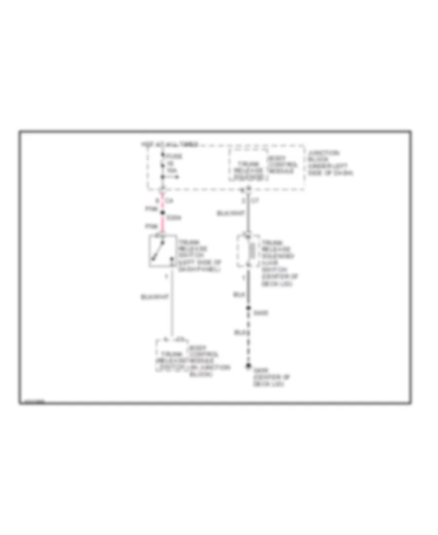
TRUNK, TAILGATE, FUEL DOOR
Trunk Release Wiring Diagram for Dodge Intrepid 1998
List of elements for Trunk Release Wiring Diagram for Dodge Intrepid 1998:
- Body control module
- Body control module (in junction block)
- Fuse 10a
- G406 (center of deck lid)
- Hot at all times
- Junction block (under left side of dash)
- Pnk
- S204
- S405
- Trunk release solenoid
- Trunk release solenoid/ ajar switch (center of deck lid)
- Trunk release switch
- Trunk release switch (left side of dash panel)
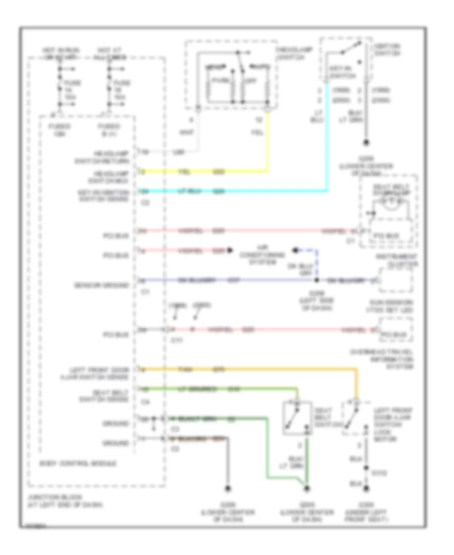
WARNING SYSTEMS
Warning System Wiring Diagrams for Dodge Intrepid 1998
List of elements for Warning System Wiring Diagrams for Dodge Intrepid 1998:
- (1999)
- (2000)
- Air conditioning system
- Auto
- Body control module
- C11
- C57
- D25
- Fuse 10a
- Fused b (+)
- Fused ign
- G10
- G206 (lower center of dash)
- G26
- G300 (under left front seat)
- G52
- G75
- Ground
- Head
- Headlamp switch
- Headlamp switch mux
- Headlamp switch return
- Hot at all times
- Hot in run or start
- Igntion switch
- Instrument cluster
- Junction block (at left end of dash)
- Key-in ignition switch sense
- Key-in switch
- L80
- Left front door ajar switch sense
- Left front door ajar switch/ lock motor
- Off
- Overhead travel information system
- Park
- Pci bus
- S208 (left side of dash)
- S312
- Seat belt switch
- Seat belt switch sense
- Seat belt warn lamp
- Sensor ground
- Sun sensor/ vtss set led
- Tan
- Z20
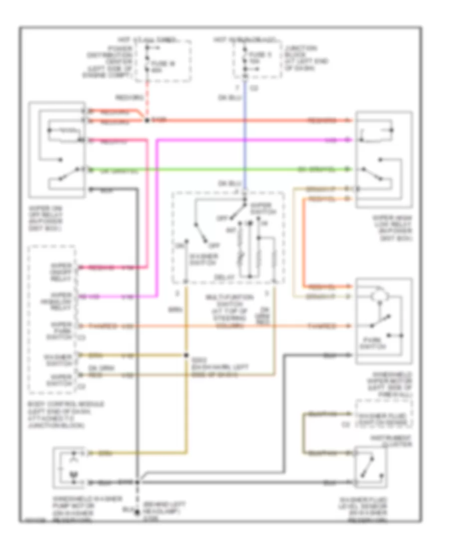
WIPER/WASHER
Wiper/Washer Wiring Diagram for Dodge Intrepid 1998
List of elements for Wiper/Washer Wiring Diagram for Dodge Intrepid 1998:
- (behind left headlamp) g106
- Body control module (left end of dash, attached to junction block)
- Delay
- Fuse 5 10a
- Fuse m 40a
- High/low relay
- Hot at all times
- Hot in run or acc
- Instrument cluster
- Int
- Junction block (at left end of dash)
- Multi-funtion switch (at top of steering column)
- Off
- On/off relay
- Park switch
- Park switch c3
- Power distribution center (left side of engine compt)
- S119
- S128
- S202 (dash harn, left side of dash)
- Tan/red
- V10
- V14
- V16
- V52
- V55
- Washer fluid level sensor (in washer reservoir)
- Washer fluid switch sense
- Washer switch
- Windshield washer pump motor (on washer reservoir)
- Windshield wiper motor (left side of firewall)
- Wiper
- Wiper high/ low relay (in power dist box)
- Wiper on/ off relay (in power dist box)
- Wiper switch
- Wiper switch c2

 Čeština
 Dansk
Dansk Deutsch
 Ελληνικά
 English
 English
 Español
 Suomi
Suomi Français
 עברית
עברית Hrvatski
 Magyar
 Italiano
 日本語
日本語 한국어
한국어 Nederlands
 Polski
 Português
 Português
 Română
 Русский
 Slovenčina
 Slovenščina
 Svenska
 Türkçe
 中文 (中国)