AIR CONDITIONING
A/C Wiring Diagram, Auto A/C for Ford Crown Victoria S 1997
 https://portal-diagnostov.com/license.html
Automotive Electricians Portal FZCO
Automotive Electricians Portal FZCO
https://portal-diagnostov.com/license.html
https://portal-diagnostov.com/license.html
Automotive Electricians Portal FZCO
Automotive Electricians Portal FZCO
List of elements for A/C Wiring Diagram, Auto A/C for Ford Crown Victoria S 1997:
- (engine harn, left rear of eng compt) s110
- (engine harn, near right front fender)
- (i/p harn, behind center of i/p)
- (i/p harn, behind right side of i/p) s200
- (i/p harn, behind top left side of i/p)
- (i/p harn, near data link conn (dlc) breakout)
- (i/p harn, near glove box lamp breakout)
- (not used)
- (top of engine, near fuel injector 1)
- A/c compressor clutch
- A/c clutch cycling pressure switch (right rear of engine compartment)
- A/c clutch diode
- A/c clutch out
- A/c cutout relay (in relay center)
- A/c high pressure cut out switch (right side of engine compartment)
- A/c plenum)
- Ambient temp input
- Ambient temperature sensor (center front of vehicle, on upper radiator support)
- Battery
- Blend door act
- Blend door actuator (behind right side of i/p, top of
- Blend door pot
- Blend door ref
- Blower motor
- Blower motor speed
- Blower motor speed controller (top right center of safety wall)
- Blower spped fback
- C227
- C228
- Cooling fan
- Cooling fan fuse 50a
- Cooling fan relay (engine compartment fuse box)
- Data link (+)
- Data link (-)
- Data link connector (dlc) (behind left side of i/p)
- Electronic automatic temperature control (eatc) module (center of i/p)
- Eng/met conv
- Engine compartment fuse box
- Fuse 15a
- Fuse 30a
- G101 (front of right front fender apron)
- G134
- Ground
- Hot at all times
- Hot in run
- I/p fuse panel
- Ignition
- Illumination
- In car temp sens
- In-car temperature sensor (behind top center of i/p)
- Instrument cluster (digital)
- Interior lights system
- Pcm power relay
- Powertrain control module (pcm) (behind left side of i/p)
- Red
- Relay signal
- S113
- S117
- S118
- S206
- S226
- S227 (i/p harness, behind left side of i/p)
- S251
- Sensor ground
- Sun load sensor (top right side of i/p, above glove box)
- Sunload sens input
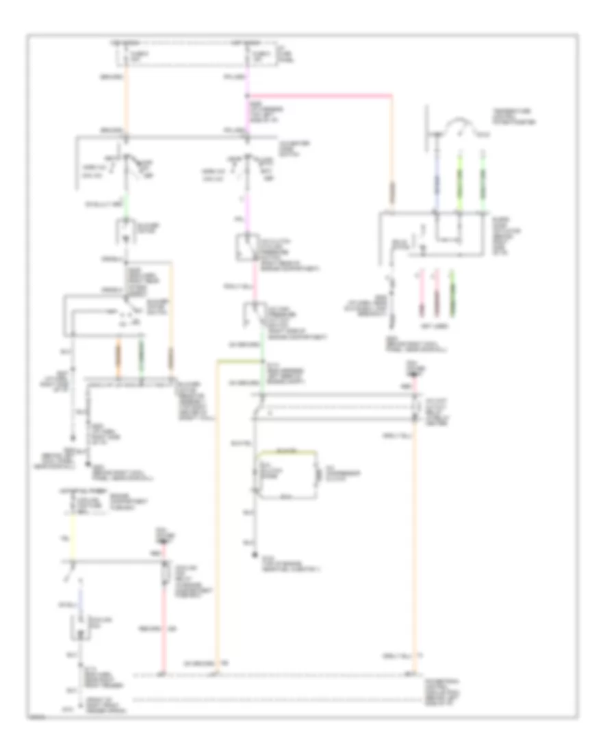
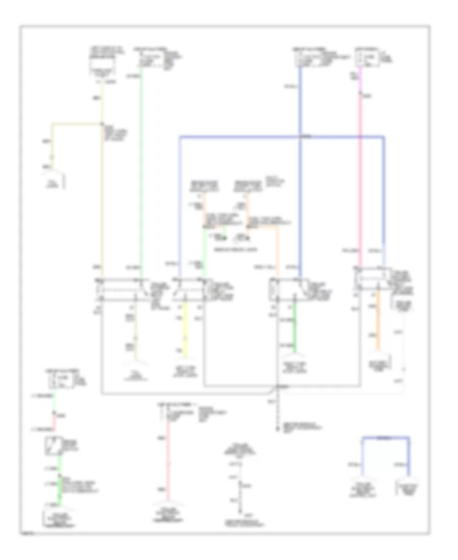
A/C Wiring Diagram, Manual A/C for Ford Crown Victoria S 1997
List of elements for A/C Wiring Diagram, Manual A/C for Ford Crown Victoria S 1997:
- (front of right front fender apron)
- (not used)
- A/c clutch cycling pressure switch (right rear of engine compartment)
- A/c clutch diode
- A/c compressor clutch
- A/c high pressure cut out switch (right side of engine compartment)
- A/c wot cutout relay (in relay center)
- A/c-heater mode switch
- Blend door actuator (behind right side of i/p)
- Blower motor
- Blower motor resistor assembly (top right center of safety wall)
- Blower motor switch
- Cold
- Cooling fan
- Cooling fan fuse 50a
- Cooling fan relay (in engine compartment fuse box)
- Def
- Engine compartment fuse box
- Floor
- Fuse 5 15a
- Fuse 9 30a
- G101
- G134 (top of engine near fuel injector 1)
- G200 (behind left cowl panel, near door sill)
- G203 (behind right cowl panel, near door sill)
- Hot at all times
- Hot in run
- I/p fuse panel
- Max a/c
- Mix
- Norm a/c
- Off
- Pcm power relay
- Pnk
- Powertrain control module (pcm) (behind left side of i/p)
- Red
- S110 (eng harness, left rear of engine compt)
- S113 (eng harn, near right front fender)
- S200 (i/p harn, right side of i/p)
- S206 (i/p harn, near glove box lamp breakout)
- S207 (i/p harn, right side of i/p)
- S226 (i/p harness, top left side of i/p)
- S239 (eng harn, right rear of eng compt)
- Solid state
- Temperature control potentiometer
- Vent
- Warm
ANTI-LOCK BRAKES
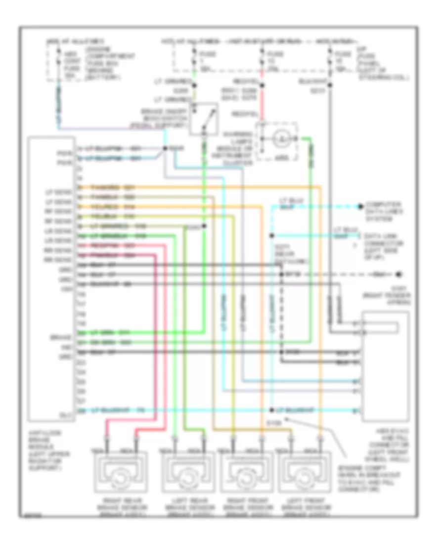
Anti-lock Brake Wiring Diagrams for Ford Crown Victoria S 1997
List of elements for Anti-lock Brake Wiring Diagrams for Ford Crown Victoria S 1997:
- (engine compt harn, in breakout to evac and fill connector)
- (ngv) (gas)
- (right fender apron)
- Abs
- Abs cont fuse 30a
- Abs evac and fill connector (left front wheel well)
- Anti-lock brake module (left upper radiator support)
- Brake
- Brake on/off (boo) switch (pedal support)
- Computer data lines system
- Data link connector (left side of i/p)
- Dlc
- Engine compartment fuse box (behind battery)
- Fuse 10a
- Fuse 15a
- G101
- Grd
- Hot at all times
- Hot in run
- Hot in start or run
- I/p fuse panel (left of steering col.)
- Ign
- Ind
- Left front brake sensor (brake ass'y)
- Left rear brake sensor (brake ass'y)
- Lf sens
- Lr sens
- Nca
- Pwr
- Red/pnk
- Rf sens
- Right front brake sensor (brake ass'y)
- Right rear brake sensor (brake ass'y)
- Rr sens
- S112
- S136
- S146
- S231
- S243
- S265
- S271 (near datalink)
- S299 s276
- Warning lamps module or instrument cluster
COMPUTER DATA LINES
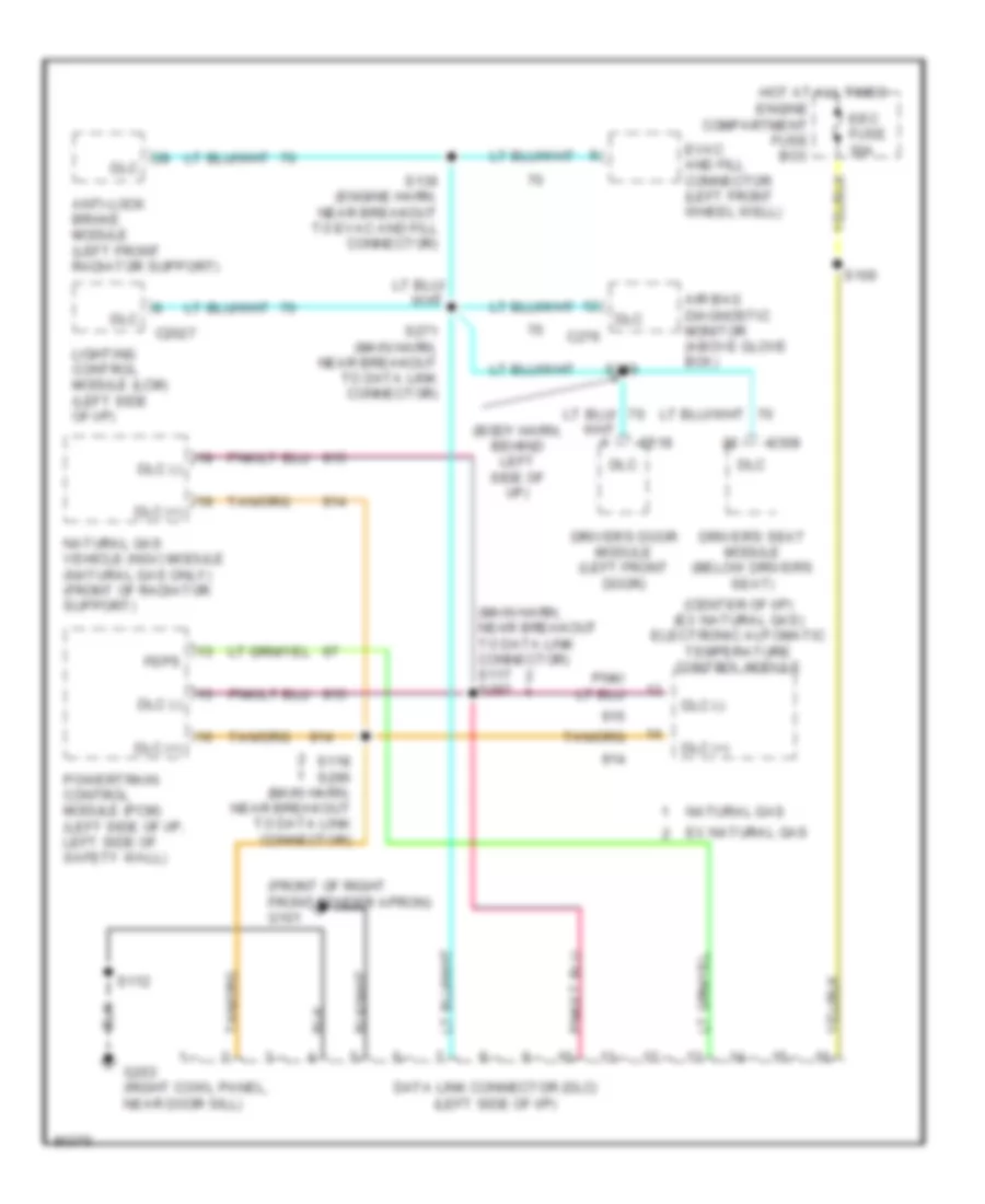
Computer Data Lines for Ford Crown Victoria S 1997
List of elements for Computer Data Lines for Ford Crown Victoria S 1997:
- (body harn, behind left side of i/p)
- (center of i/p) (ex natural gas) electronic automatic temperature control module
- (front of right front fender apron) g101
- (main harn, near breakout to data link connector) s117 s297
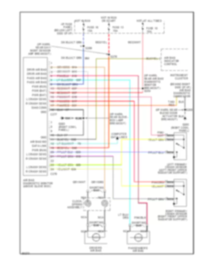
- Air bag diagnostic monitor (above glove box)
- Anti-lock brake module (left front radiator support)
- C2027
- C276
- C308
- C518
- Data link connector (dlc) (left side of i/p)
- Dlc
- Dlc (+)
- Dlc (-)
- Driver's door module (left front door)
- Driver's seat module (below driver's seat)
- Eec fuse 30a
- Engine compartment fuse box
- Evac and fill connector (left front wheel well)
- Ex natural gas
- Feps
- G203 (right cowl panel, near door sill)
- Hot at all times
- Lighting control module (lcm) (left side of i/p)
- Natural gas
- Natural gas vehicle (ngv) module (natural gas only) (front of radiator support)
- Powertrain control module (pcm) (left side of i/p, left side of safety wall)
- S100
- S112
- S118 s296 (main harn, near breakout to data link connector)
- S136 (engine harn, near breakout to evac and fill connector)
- S271 (main harn, near breakout to data link connector)
- S286
COOLING FAN
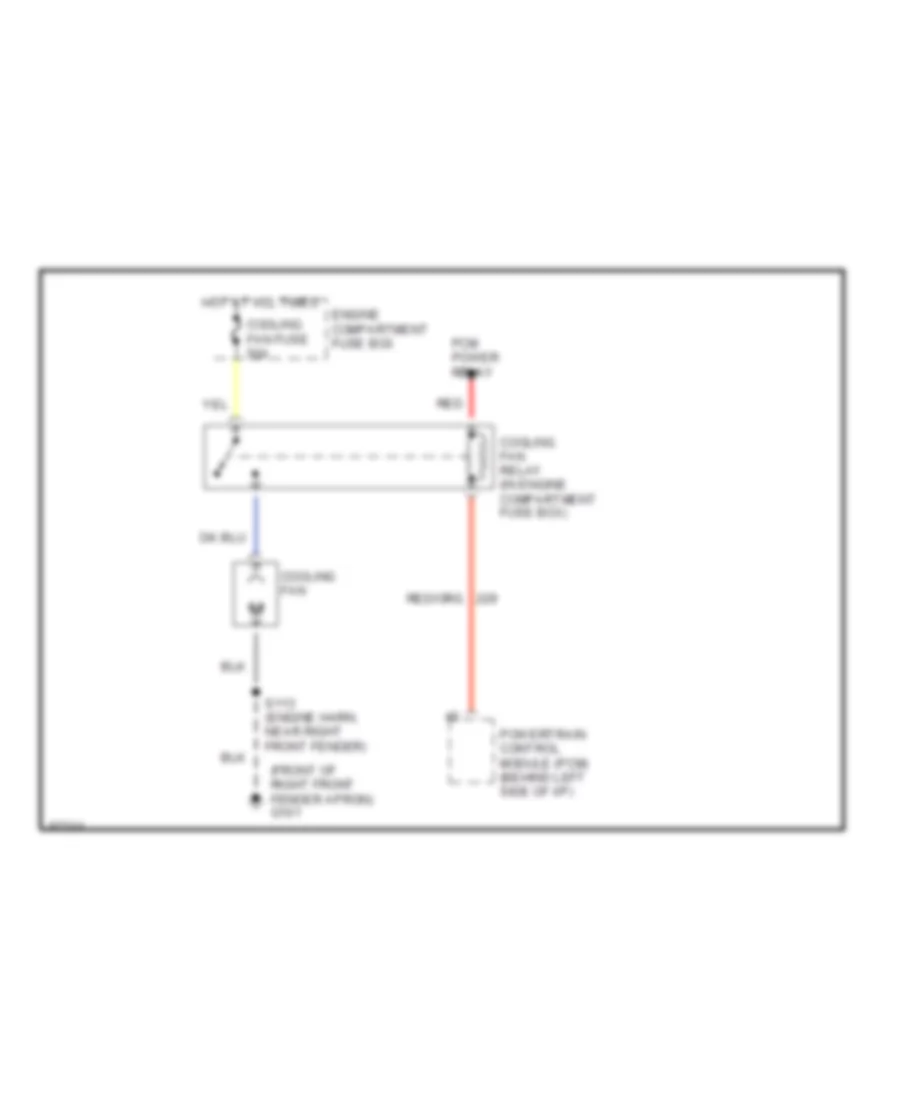
Cooling Fan Wiring Diagram for Ford Crown Victoria S 1997
List of elements for Cooling Fan Wiring Diagram for Ford Crown Victoria S 1997:
- (front of right front fender apron) g101
- Cooling fan
- Cooling fan fuse 50a
- Cooling fan relay (in engine compartment fuse box)
- Engine compartment fuse box
- Hot at all times
- Pcm power relay
- Powertrain control module (pcm) (behind left side of i/p)
- Red
- S113 (engine harn, near right front fender)
CRUISE CONTROL
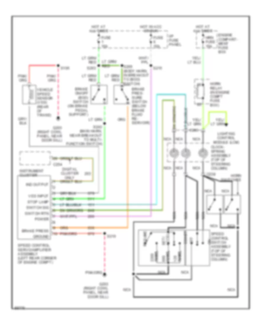
Cruise Control Wiring Diagram for Ford Crown Victoria S 1997
List of elements for Cruise Control Wiring Diagram for Ford Crown Victoria S 1997:
- Brake on/off (boo) switch (on brake pedal support)
- Brake pres- sure switch (below brake fluid re- servoir)
- Brake press
- C238
- C254
- C283
- Clock- spring assembly (top of steering column)
- Coast
- Digital cluster only
- Engine compart- ment fuse box
- Fuse 15a
- G203 (right cowl panel, near door sill)
- Ground
- Horn relay (in engine compt fuse box)
- Horn switches
- Hot at all times
- Hot in acc or run
- Hrn fuse 15a
- I/p fuse panel
- Ind output
- Instrument cluster
- Lighting control module (lcm)
- Nca
- Off
- Ohms
- Power
- Resume
- S105
- S210
- S215
- S243 (main harn, near breakout to multi- function switch)
- S263
- Set/ accel
- Speed control servo/amplifier assembly (left rear corner of engine compt)
- Speed control switch assembly (top of steering column)
- Stop lamp
- Switch rtn
- Switch sig
- To (boo) switch)
- Vehicle speed sensor (vss) (rear of trans)
- Vss input
DEFOGGERS
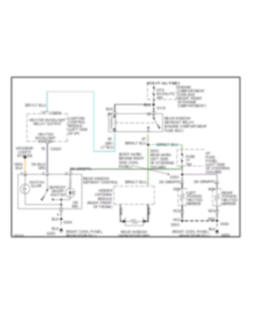
Defogger Wiring Diagram for Ford Crown Victoria S 1997
List of elements for Defogger Wiring Diagram for Ford Crown Victoria S 1997:
- (body harn, behind right side cowl panel)
- (right cowl panel, near door sill)
- C2026
- Defrost on/off switch
- Engine compartment fuse box (right front of engine compartment)
- Fuse 10a
- G203
- Heated backlight relay output
- Heated backlight switch
- Hidden antenna module (right front of trunk)
- Hot at all times
- Htd backlite 40a
- I/p fuse panel (left side of steering column)
- Interior lights system
- Left power/ heated mirror
- Lighting control module (left side of i/p)
- Nca
- On ind.
- Rear window defrost control
- Rear window defrost relay (engine compartment fuse box)
- Rear window defroster grid
- Right power/ heated mirror
- S119
- S204
- S252 (main harn, left side of steering column)
- S253
- S503
- S600
- Switch illum.
ELECTRONIC POWER STEERING
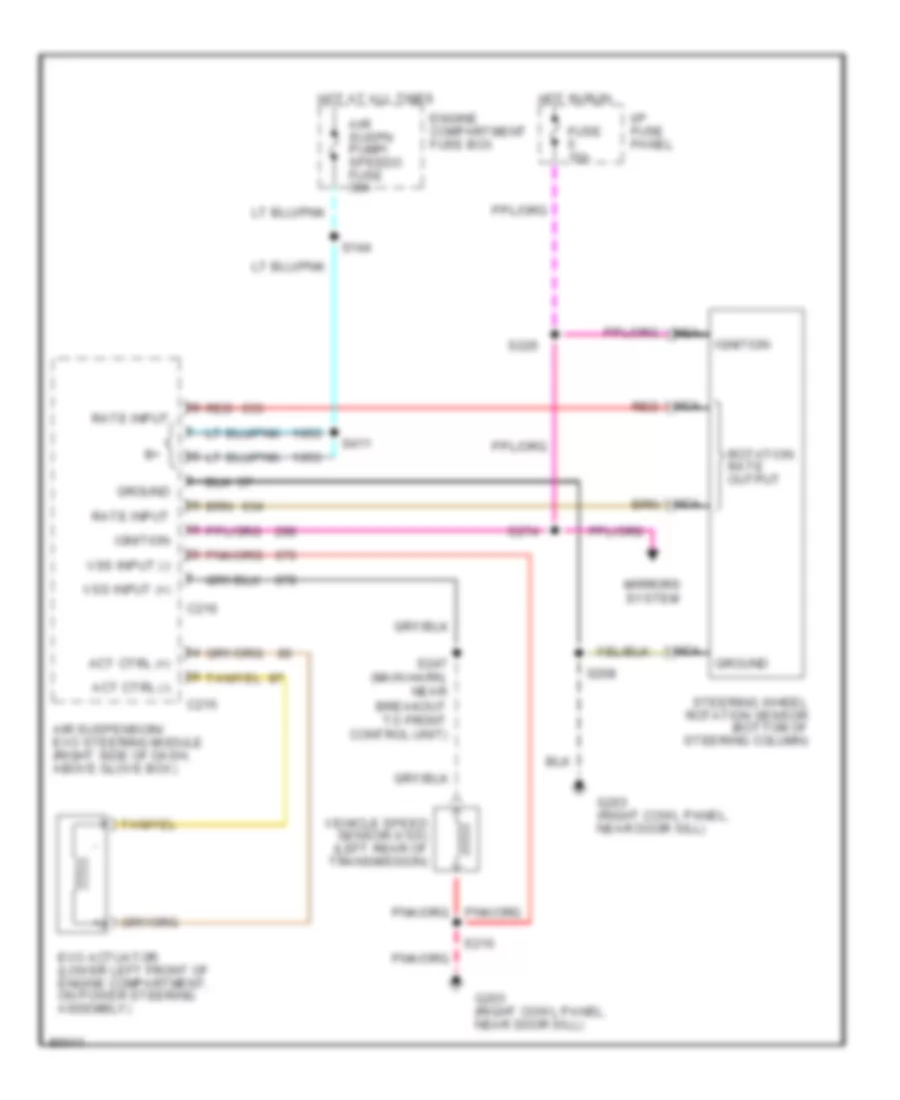
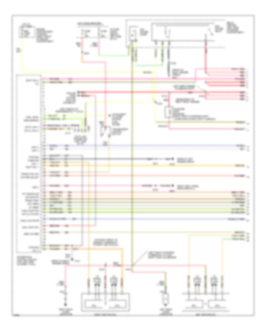
Electronic Power Steering Wiring Diagram, with Air Suspension for Ford Crown Victoria S 1997
List of elements for Electronic Power Steering Wiring Diagram, with Air Suspension for Ford Crown Victoria S 1997:
- Act ctrl (+)
- Act ctrl (-)
- Air suspension/ evo steering module (right side of dash, above glove box)
- Air suspn pump/ speedo fuse 30a
- C215
- C216
- Engine compartment fuse box
- Evo actuator (lower left front of engine compartment, on power steering assembly)
- Fuse 15a
- G203 (right cowl panel, near door sill)
- Ground
- Hot at all times
- Hot in run
- I/p fuse panel
- Ignition
- Mirrors system
- Nca
- Rate input
- Red
- Rotation rate output
- S144
- S208
- S210
- S226
- S247 (main harn, near breakout to front control unit)
- S274
- S411
- Steering wheel rotation sensor (bottom of steering column)
- Vehicle speed sensor (vss) (left rear of transmission)
- Vss input (+)
- Vss input (-)
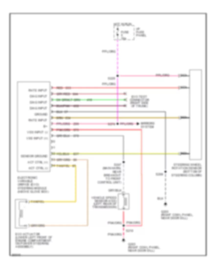
Electronic Power Steering Wiring Diagram, without Air Suspension for Ford Crown Victoria S 1997
List of elements for Electronic Power Steering Wiring Diagram, without Air Suspension for Ford Crown Victoria S 1997:
- Act ctrl (+)
- Act ctrl (-)
- Diag input
- Electronic variable orifice (evo) steering module (above glove box)
- Evo actuator (lower left front of engine compartment, on power steering assembly)
- Evo test connector (right side of trunk)
- Fuse 15a
- G203 (right cowl panel, near door sill)
- Ground
- Hot in run
- I/p fuse panel
- Mirrors system
- Nca
- Rate input
- Red
- S208
- S210
- S226
- S247 (main harn, near breakout to front control unit)
- S274
- Sensor ground
- Steering wheel rotation sensor (bottom of steering column)
- Vehicle speed sensor (vss) (left rear of transmission)
- Vss input (+)
- Vss input (-)
ELECTRONIC SUSPENSION
Electronic Suspension Wiring Diagram for Ford Crown Victoria S 1997
List of elements for Electronic Suspension Wiring Diagram for Ford Crown Victoria S 1997:
- (above glove box)
- (below air cleaner assembly)
- (body harn, near
- (bottom of steering column)
- (engine compartment fuse box)
- (left rear upper control arm)
- (luggage compt harn,
- (main harn, near
- (on power steering assembly)
- (rear of transmission)
- (right cowl panel,
- (right side
- (right side of trunk)
- 15a
- 30a
- 87a
- Air
- Air spring
- Air suspension
- Air suspension compressor
- Air suspension/evo steering module
- Air suspn
- Airbag diagnostic
- All times
- Analog
- Battery pwr
- Breakout to
- C215
- C216
- C251
- C255
- C256
- Check air
- Cluster
- Comp relay ctrl
- Compartment
- Compressor relay
- Connector)
- Diagnostic input
- Digital
- Door open input
- Engine
- Evo actuator
- Evo actuator ctrl +
- Evo actuator ctrl -
- Frt ctrl unit)
- Fuse
- Fuse box
- G101
- G203
- Ground
- Hgt sensor ground
- Hgt sensor input
- Hgt sensor pwr
- Hot at
- Hot in run
- I/p
- Ign
- Ignition on input
- Indicator
- Instrument
- Interior
- L rear spring sol
- Left rear
- Lights
- Linear height sensor
- Motor and vent solenoid
- Near breakout to
- Near door sill)
- Panel
- Pnk
- Pnk 421
- Pump/
- Red
- Red 633
- Right rear
- Right rear speaker)
- Rt rear spring sol
- S112
- S144
- S208
- S210
- S247
- S269
- S274
- S300
- S403
- S411
- S431
- Service input
- Solenoid
- Speedo
- Steering rotate rate
- Steering wheel rotation sensor
- Suspension
- Switch
- System
- Test connector
- Vehicle spd input +
- Vehicle spd input -
- Vehicle speed sensor
- Vent sol ctrl
- Warning lt output
ENGINE PERFORMANCE
4.6L
4.6L CNG, Engine Performance Wiring Diagrams (1 of 5) for Ford Crown Victoria S 1997
List of elements for 4.6L CNG, Engine Performance Wiring Diagrams (1 of 5) for Ford Crown Victoria S 1997:
- (front of right fender apron) g101
- (front of engine compt, near breakout to ngv module)
- (front of right fender apron)
- (left front of engine, in breakout to camshaft position sensor)
- (left rear corner of eng compt)
- (left side of i/p, near breakout to dlc)
- (rear of left fender apron)
- (rear of left front fender apron)
- (right cowl panel, near door sill)
- (top right front of engine, in breakout to right ignition coil)
- A/c clutch sig
- C2021
- Case gnd
- Ckp (+)
- Ckp (-)
- Coil
- Coil 1
- Coil 2
- Cool fan ctrl
- Cooling fans system (cooling fan relay)
- Crankshaft position (ckp) sensor (lower right front of engine)
- Crankshaft position sensor shield
- Data link (+)
- Data link (-)
- Data link connector (left side of i/p)
- Ect sens
- Eec fuse 30a
- Egr vac reg
- Engine compartment fuse box (right front of engine compartment)
- Feps (eprom)
- Fuel pump mon
- Fuel rail sens
- Fuse 15a
- Fuse 25a
- G101
- G104
- G203
- Hot at all times
- Hot in run or start
- I/p fuse panel (below left side of i/p)
- Iat sens
- Left ignition coil
- Left radio noise capacitor
- Maf sig rtn
- Mil
- Nca
- Octane adjust
- Pcm power diode
- Pcm power relay
- Powertrain control module (top left side of safety wall)
- Pwr gnd
- Red
- Relay center (left side of engine compartment)
- Right ignition coil
- Right radio noise capacitor
- S100
- S101
- S102
- S103
- S105
- S114
- S117
- S118
- S129
- S151
- S197
- S276
- Shift sol 1
- Shift sol 2
- To spark plugs 1 & 6
- To spark plugs 2 & 8
- To spark plugs 3 & 5
- To spark plugs 4 & 7
- Trans ctrl sw
- Trans temp
- Transmission control switch
- Vss (-)
4.6L CNG, Engine Performance Wiring Diagrams (2 of 5) for Ford Crown Victoria S 1997
List of elements for 4.6L CNG, Engine Performance Wiring Diagrams (2 of 5) for Ford Crown Victoria S 1997:
- (a/c high pressure cut out switch) air conditioning system
- (left rear of engine compt)
- (left side of engine compt)
- (left side of i/p, near breakout to cluster)
- (lower right rear of engine, near breakout to right heated oxygen sensor 1)
- A/c wot cutout relay
- Differential pressure feedback egr sensor (near right side of intake manifold)
- Engine compartment fuse box (right front of engine compartment)
- Engine coolant temperature sensor (top left front of engine)
- Fuel level input
- Fuel pmp fuse 20a
- Fuel rail pressure sensor (top of engine)
- Fuel rail temperature sensor #1 (top of engine)
- Fuel valve relay
- Ground
- Hot at all times
- Instrument cluster
- Intake air temperature sensor (rear of air cleaner assembly)
- Malfunction indicator lamp
- Octane adjust plug (left side of engine compartment)
- Power
- Red
- Red/pnk
- Relay center (left side of engine compartment)
- S110
- S125
- S126
- S130
- S147 (left side of engine compt)
- S299
- Throttle position sensor (left side of throttle body)
- Transmission control indicator input
- Vss (+)
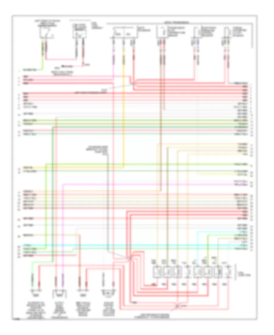
4.6L CNG, Engine Performance Wiring Diagrams (3 of 5) for Ford Crown Victoria S 1997
List of elements for 4.6L CNG, Engine Performance Wiring Diagrams (3 of 5) for Ford Crown Victoria S 1997:
- (center rear of engine, in breakout to dpfe sensor)
- (on engine near breakout to fuel injector 8) s131
- 4r70w transmission
- Egr vacuum regulator solenoid (top center rear of engine)
- Electronic pressure control solenoid
- Fuel injectors
- Idle air control valve (left side of intake manifold)
- Output shaft speed sensor (left rear of transmission)
- Red
- Red/pnk
- S143
- S148 (left side of engine compt)
- Shift solenoids
- Ss1
- Ss2
- Tan
- Tan/ red
- Tan/red
- Torque converter clutch solenoid
- Transmission fluid temperature sensor
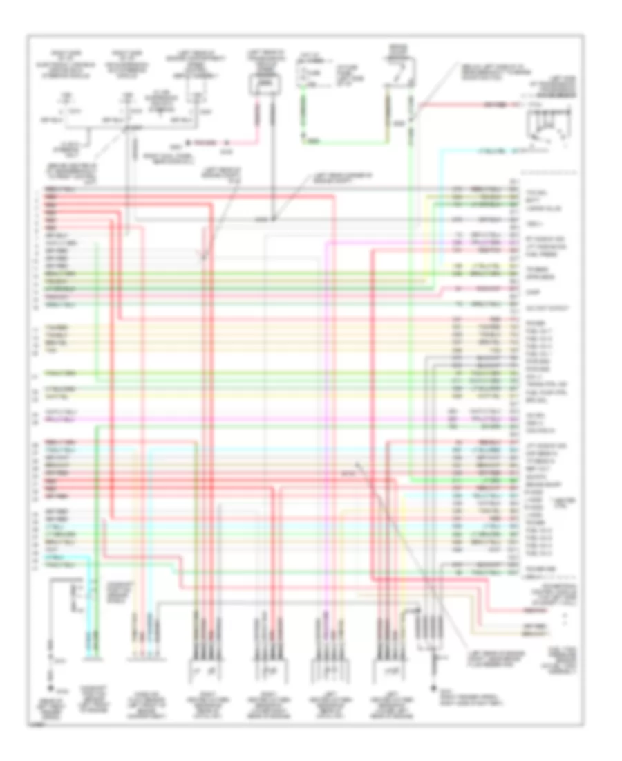
4.6L CNG, Engine Performance Wiring Diagrams (4 of 5) for Ford Crown Victoria S 1997
List of elements for 4.6L CNG, Engine Performance Wiring Diagrams (4 of 5) for Ford Crown Victoria S 1997:
- (behind left cowl panel)
- (center rear of trunk, on support)
- (fuel tank assembly) fuel tank assembly temperature sensor #1
- (fuel tank assembly) fuel tank assembly temperature sensor #2
- (fuel tank assembly) fuel tank pressure sensor
- (fuel tank assembly) fuel tank solenoid valve #1
- (fuel tank assembly) fuel tank solenoid valve #2
- (fuel tank assembly) fuel tank solenoid valve #3
- (fuel tank assembly) fuel tank solenoid valve #4
- (in fuel tank assy, near breakout to fuel tank solenoid valve 4)
- (left side of trunk)
- (left side of trunk) inertia fuel shut-off switch
- (near #1 fuel injector)
- (right front fender apron, right side of battery)
- (top of engine) fuel rail cutoff solenoid
- (top of engine) fuel rail temperature sensor #2
- Data (+)
- Data (-)
- G101
- G101 (right front fender apron, right side of battery)
- G134
- G407
- Ground
- I/p
- Ignition
- Injector #1 input
- Injector #1 out
- Injector #2 input
- Injector #2 out
- Injector #3 input
- Injector #3 out
- Injector #4 input
- Injector #4 out
- Injector #5 input
- Injector #5 out
- Injector #6 input
- Injector #6 out
- Injector #7 input
- Injector #7 out
- Injector #8 input
- Injector #8 out
- Natural gas vehicle (ngv) module (front of engine compartment)
- Power
- Red
- Red/pnk
- Ref voltage
- S112
- S141
- S298
- S405
- S427
- S429
- S430
- Tan
- Tan/red
- Temp sens #1
- Temp sens #2
- Transducer input
- Transducer ret
4.6L CNG, Engine Performance Wiring Diagrams (5 of 5) for Ford Crown Victoria S 1997
List of elements for 4.6L CNG, Engine Performance Wiring Diagrams (5 of 5) for Ford Crown Victoria S 1997:
- (behind center of i/p, near breakout to front control unit)
- (below left side of i/p, near breakout to brake on/off switch)
- (left rear corner of engine compt)
- (left rear of engine compartment) speed control servo assembly
- (left rear of engine compt)
- (left rear of transmission) vehicle speed sensor
- (left side of transmission) transmission range sensor
- (rear of left front fender apron)
- (right cowl panel, near door sill)
- (right side of i/p) air suspension/ evo steering module
- (right side of i/p) electronic variable orifice (evo) steering module
- A/c wot cutout
- Batt
- Brake on/off
- Brake on/off switch
- C214
- C216
- C234
- Cam pos in
- Camshaft position sensor (left front of engine)
- Camshaft position sensor shield
- Coil 3
- Coil 4
- Dpfe sens
- Epc sol
- Fuel inj 1
- Fuel inj 2
- Fuel inj 3
- Fuel inj 4
- Fuel inj 5
- Fuel inj 6
- Fuel inj 7
- Fuel inj 8
- Fuel pump ctrl
- Fuel rail press
- Fuel rail temp
- Fuse 15a
- G101 (right fender apron, right side of battery)
- G104
- G203
- Heater ctrl
- Hot at all times
- I/p fuse panel (left side of i/p)
- Iac sol
- L ho2s
- Left heated oxygen sensor #1 (lower left rear of engine)
- Lft ho2s #1 sig
- Maf sens in
- Mass air flow sensor (left front of engine compartment)
- Nca
- Oss (+)
- Power
- Power gnd
- Powertrain control module (top left side of safety wall)
- Pwr gnd
- R ho2s
- Red
- Red/pnk
- Ref volt
- Right heated oxygen sensor #1 (lower right rear of engine)
- Rt ho2s #1 sig
- S101
- S105
- S106
- S109
- S114
- S147
- S247
- S258
- S263
- Sig rtn
- Tan
- Tan/red
- Tcc sol
- Tp sens in
- Tr sens
- Trans ctrl ind
- Vss (+)
- Vss (-)
- W/ air suspension and evo steering
- W/ evo steering only
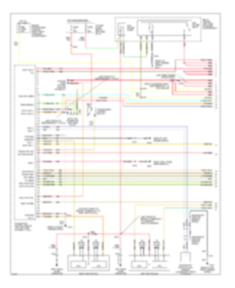
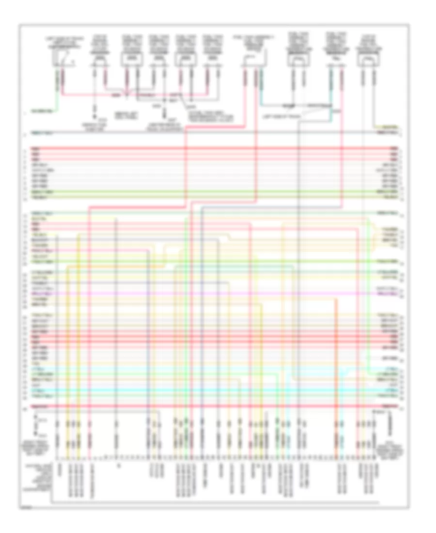
4.6L, Engine Performance Wiring Diagrams (1 of 4) for Ford Crown Victoria S 1997
List of elements for 4.6L, Engine Performance Wiring Diagrams (1 of 4) for Ford Crown Victoria S 1997:
- (front of right fender apron) g101
- (front of right fender apron)
- (inside front of right front fender)
- (left front of engine in breakout to cam- shaft position sensor)
- (left rear corner of engine compt)
- (left side of i/p, near breakout to dlc)
- (rear of left fender apron)
- (right cowl panel, near door sill)
- (top right front of engine, in breakout to right ignition coil)
- A/c clutch sig
- C2021
- Canister vent solenoid (right front of engine compt, lower side of eng compt fuse box)
- Case gnd
- Ckp (+)
- Ckp (-)
- Coil
- Coil 1
- Coil 2
- Cool fan ctrl
- Cooling fans system (cooling fan relay)
- Data link (+)
- Data link (-)
- Data link connector (left side of i/p)
- Ect sens
- Eec fuse 30a
- Egr vac reg
- Engine compartment fuse box (right front of engine compartment)
- Feps (eprom)
- Fuel flow rate
- Fuel level
- Fuel pump mon
- Fuse 15a
- Fuse 25a
- G101
- G104
- G203
- Hot at all times
- Hot in run or start
- I/p fuse panel (below left side of i/p)
- Iat sens
- Instrument cluster system (fuel gauge)
- Left ignition coil
- Left radio noise capacitor
- Maf sig rtn
- Mil
- Nca
- Octane adjust
- Pcm power diode
- Pcm power relay
- Powertrain control module (top left side of safety wall)
- Pwr gnd
- Red
- Relay center (left side of engine compartment)
- Right ignition coil
- Right radio noise capacitor
- Rt ho2s #2 sig
- S100
- S101
- S102
- S103
- S105
- S106
- S116
- S117
- S118
- S129
- S276
- Shift sol 1
- Shift sol 2
- To spark plugs 1 & 6
- To spark plugs 2 & 8
- To spark plugs 3 & 5
- To spark plugs 4 & 7
- Trans ctrl sw
- Trans temp
- Transmission control switch
- Vss (-)
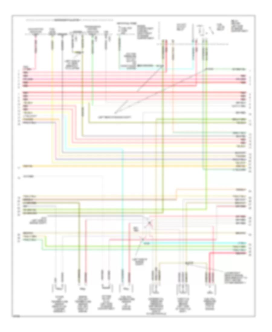
4.6L, Engine Performance Wiring Diagrams (2 of 4) for Ford Crown Victoria S 1997
List of elements for 4.6L, Engine Performance Wiring Diagrams (2 of 4) for Ford Crown Victoria S 1997:
- (a/c high pressure cut out switch) air conditioning system
- (left rear of engine compt)
- (left side of engine compt)
- (left side of engine compt, near breakout to fuel pump prime connector)
- (speedometer/ odometer) vehicle speed input
- C255
- Crankshaft position (ckp) sensor (lower right front of engine)
- Crankshaft position sensor shield
- Differential pressure feedback egr sensor (near right side of intake manifold)
- Digital only
- Engine compartment fuse box (right front of engine compartment)
- Engine coolant temperature sensor (top left front of engine)
- Fuel flow rate input
- Fuel pmp fuse 20a
- Fuel pump prime connector (left side of engine compartment)
- Fuel pump relay
- G104 (rear of left front fender apron)
- Hot at all times
- Instrument cluster
- Intake air temperature sensor (rear of air cleaner assembly)
- Malfunction indicator input
- Octane adjust plug (left side of engine compartment)
- Red
- Relay center (left side of engine compartment)
- S101
- S110
- S124
- S125
- S126 (lower right rear of engine, near breakout to right heated oxygen sensor 1)
- S130
- S147
- Throttle position sensor (left side of throttle body)
- Transmission control indicator input
- Wot cutout relay
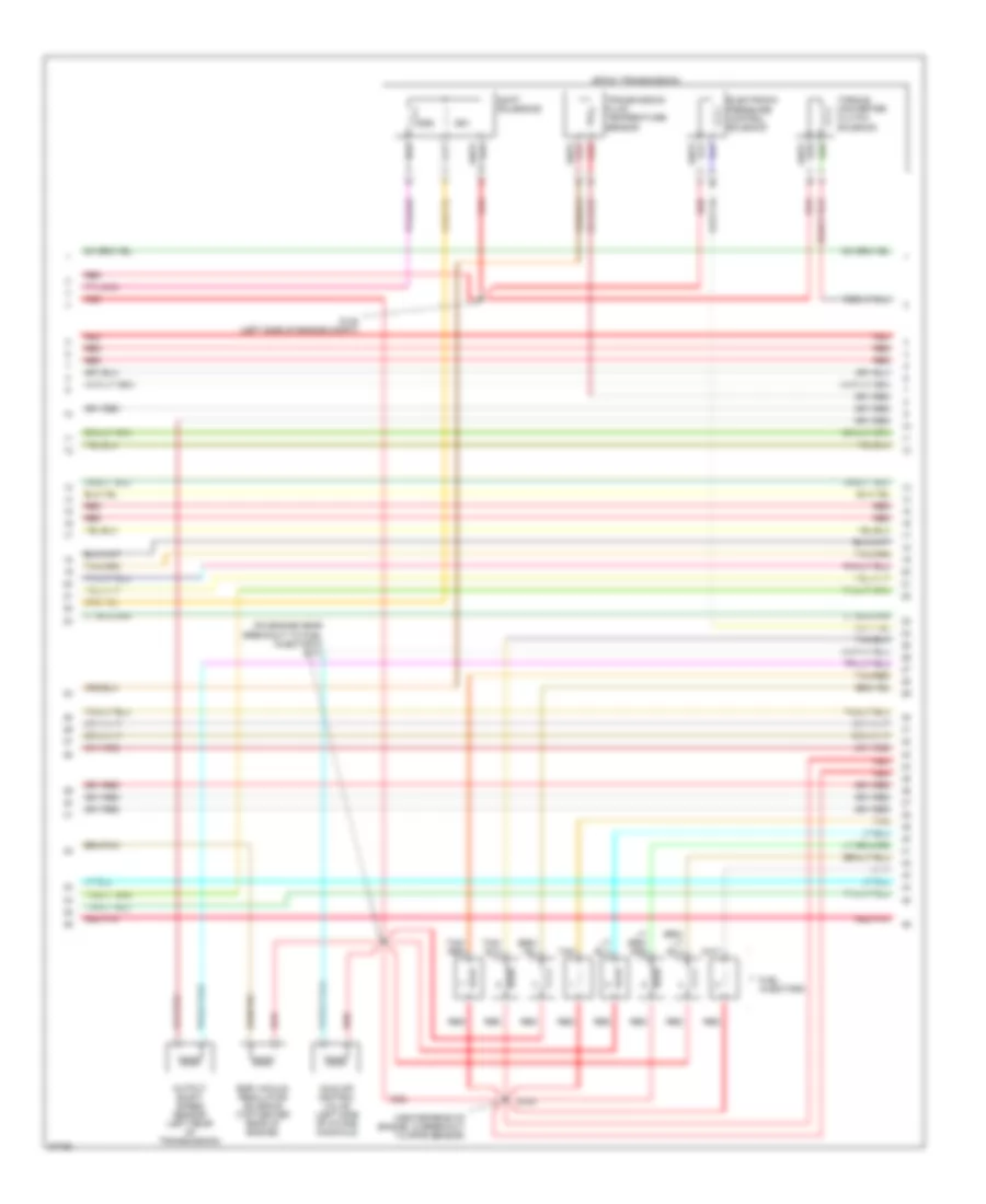
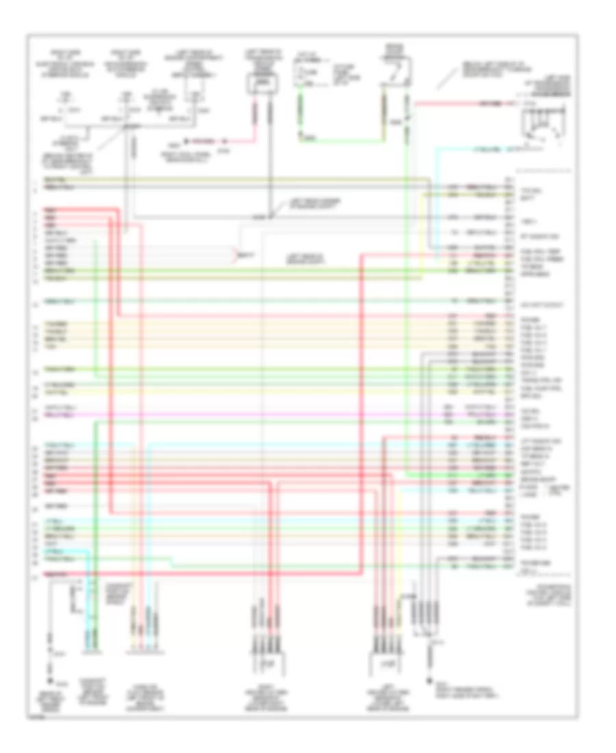
4.6L, Engine Performance Wiring Diagrams (3 of 4) for Ford Crown Victoria S 1997
List of elements for 4.6L, Engine Performance Wiring Diagrams (3 of 4) for Ford Crown Victoria S 1997:
- (center rear of engine, in breakout to dpfe sensor)
- (left front of trunk) inertia fuel shutoff switch
- (on engine, near breakout to fuel injector 8) s131
- (rear center of of engine) compartment)
- (right cowl panel, near door sill)
- 4r70w transmission
- Egr vacuum regulator solenoid (top center rear of engine)
- Electronic pressure control solenoid
- Evaporative emission (evap) canister purge valve
- Fuel injectors
- Fuel pump/ fuel gauge sender
- Fuel tank assembly
- G203
- Idle air control valve (left side of intake manifold)
- Nca
- Output shaft speed sensor (left rear of transmission)
- Red
- S143
- S148 (left side of engine compt)
- S402
- Shift solenoids
- Ss1
- Ss2
- Tan
- Tan/ red
- Tan/red
- Torque converter clutch solenoid
- Transmission fluid temperature sensor
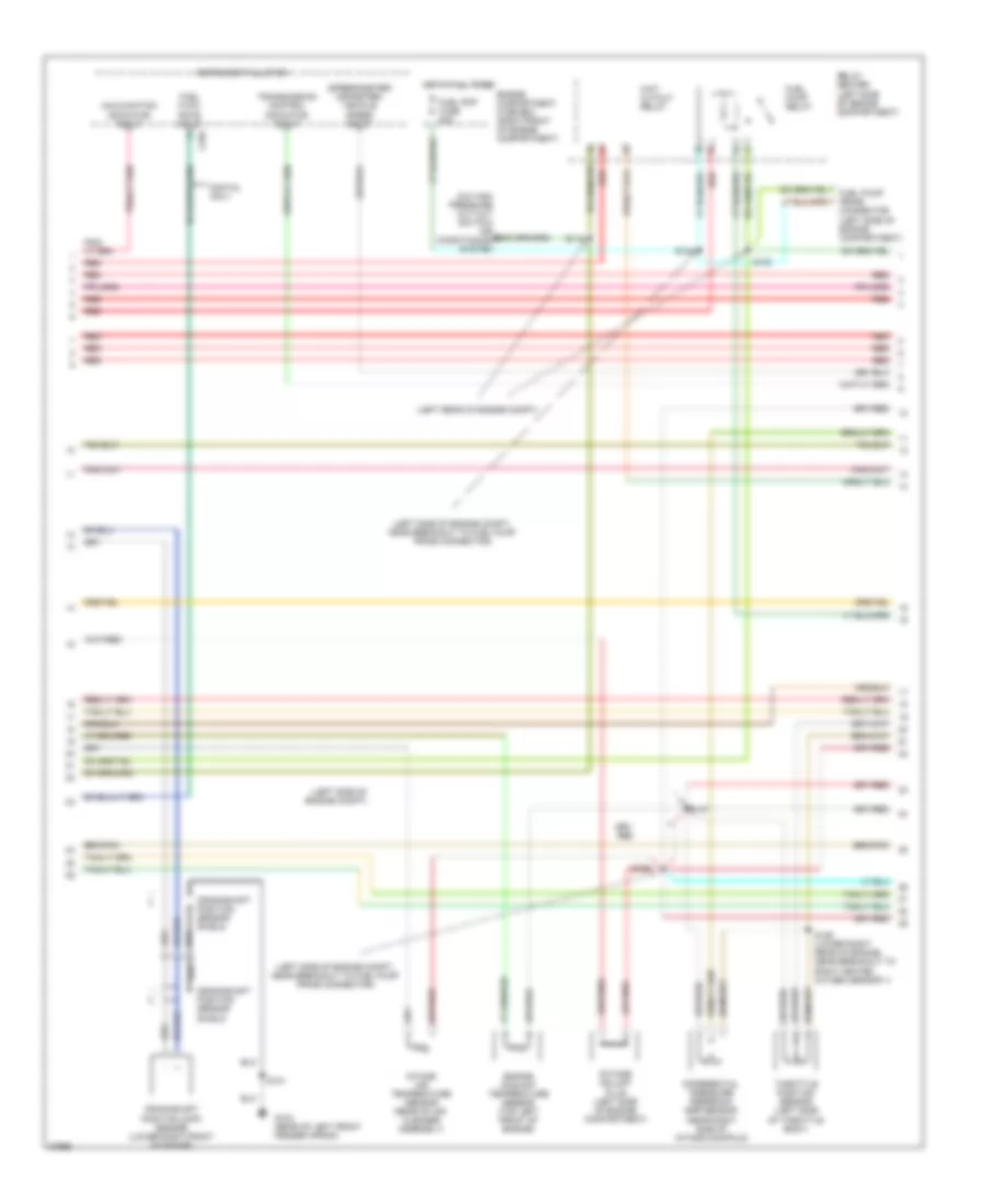
4.6L, Engine Performance Wiring Diagrams (4 of 4) for Ford Crown Victoria S 1997
List of elements for 4.6L, Engine Performance Wiring Diagrams (4 of 4) for Ford Crown Victoria S 1997:
- (behind center of i/p, near breakout to front control unit)
- (below left side of i/p, near breakout to brake on/off switch)
- (left rear corner of engine compt)
- (left rear of engine compartment) speed control servo assembly
- (left rear of engine compt) s147
- (left rear of engine compt, near brake fluid reservoir)
- (left rear of transmission) vehicle speed sensor
- (left side of transmission) transmission range sensor
- (rear of left front fender apron)
- (right cowl panel, near door sill)
- (right side of i/p) air suspension/ evo steering module
- (right side of i/p) electronic variable orifice (evo) steering module
- A/c wot cutout
- Batt
- Brake on/off
- Brake on/off switch
- C214
- C216
- C234
- Cam pos in
- Camshaft position sensor (left front of engine)
- Camshaft position sensor shield
- Canp
- Coil 3
- Coil 4
- Dpfe sens
- Epc sol
- Fuel inj 1
- Fuel inj 2
- Fuel inj 3
- Fuel inj 4
- Fuel inj 5
- Fuel inj 6
- Fuel inj 7
- Fuel inj 8
- Fuel press
- Fuel pump ctrl
- Fuel tank pressure sensor (in fuel tank assembly)
- Fuse 15a
- G101 (right fender apron, right side of battery)
- G104
- G203
- Heater ctrl
- Hot at all times
- I/p fuse panel (left side of i/p)
- Iac sol
- L ho2s
- Left heated oxygen sensor #1 (lower left rear of engine)
- Left heated oxygen sensor #2 (rear of catalyst)
- Lft ho2s #1 sig
- Lft ho2s #2 sig
- Maf sens in
- Mass air flow sensor (left front of engine compartment)
- Nca
- Oss (+)
- Power
- Power gnd
- Powertrain control module (top left side of safety wall)
- Pwr gnd
- R ho2s
- Red
- Red/pnk
- Ref volt
- Right heated oxygen sensor #1 (lower right rear of engine)
- Right heated oxygen sensor #2 (rear of catalyst)
- Rt ho2s #1 sig
- S101
- S105
- S106
- S109
- S114
- S115
- S247
- S258
- S263
- Sig rtn
- Tan
- Tan/red
- Tcc sol
- Tp sens in
- Tr sens
- Trans ctrl ind
- Vapor valve
- Vss (+)
- Vss (-)
- W/ air suspension and evo steering
- W/ evo steering only
EXTERIOR LIGHTS
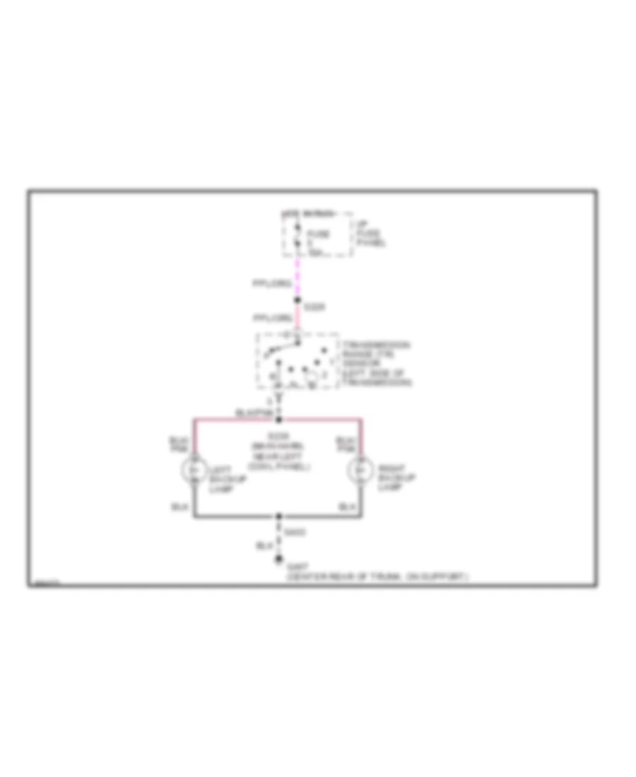
Back-up Lamps Wiring Diagram for Ford Crown Victoria S 1997
List of elements for Back-up Lamps Wiring Diagram for Ford Crown Victoria S 1997:
- Fuse 15a
- G407 (center rear of trunk, on support)
- Hot in run
- I/p fuse panel
- Left backup lamp
- Right backup lamp
- S226
- S230 (main harn, near left cowl panel)
- S403
- Transmission range (tr) sensor (left side of transmission)
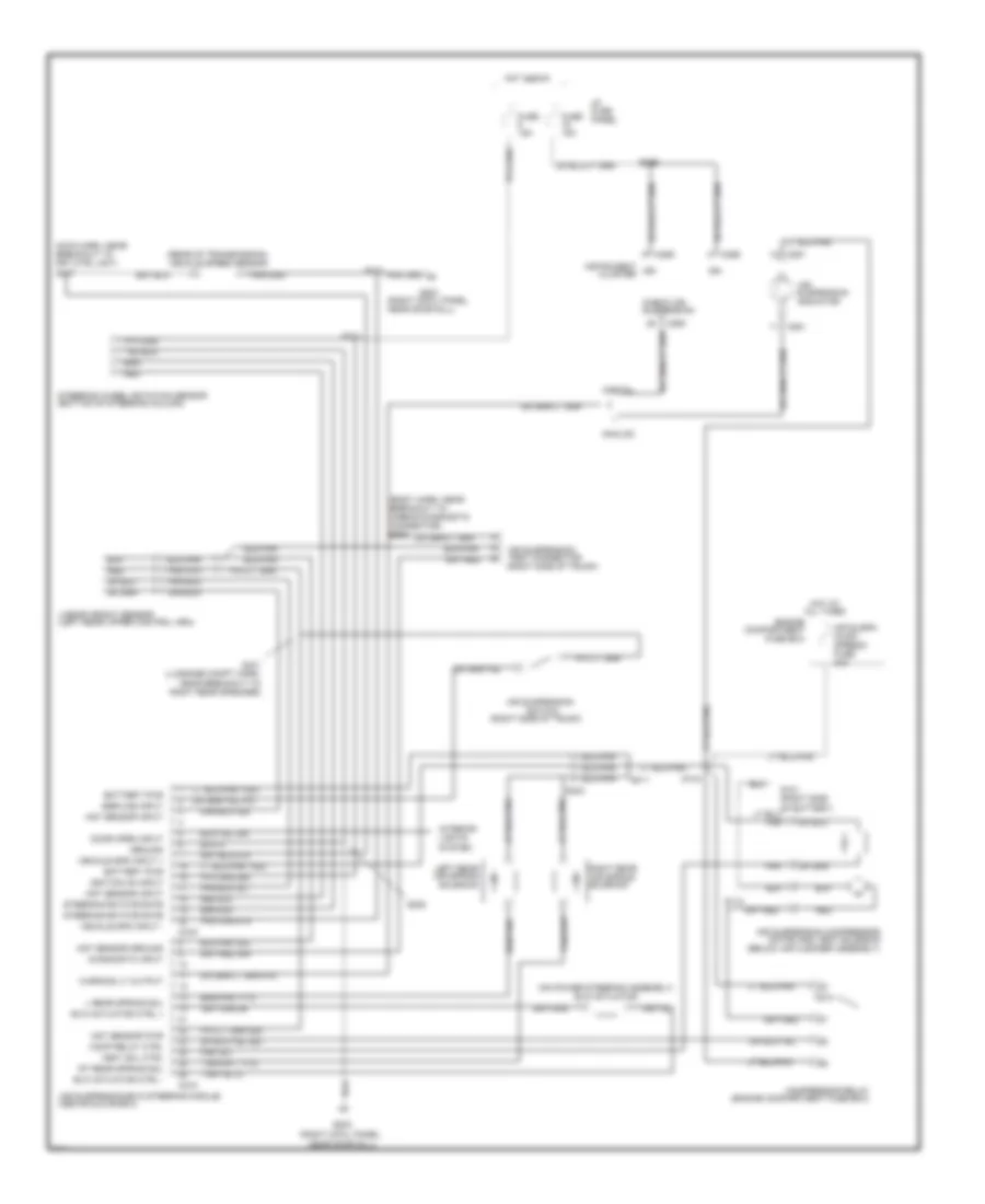
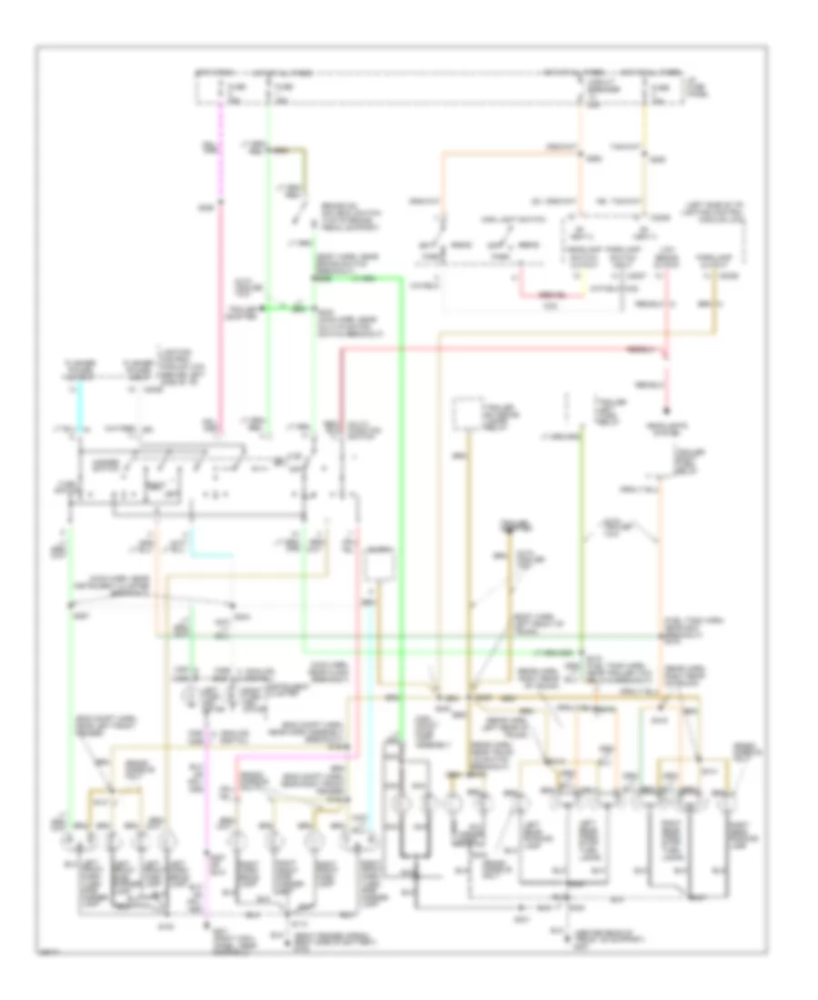
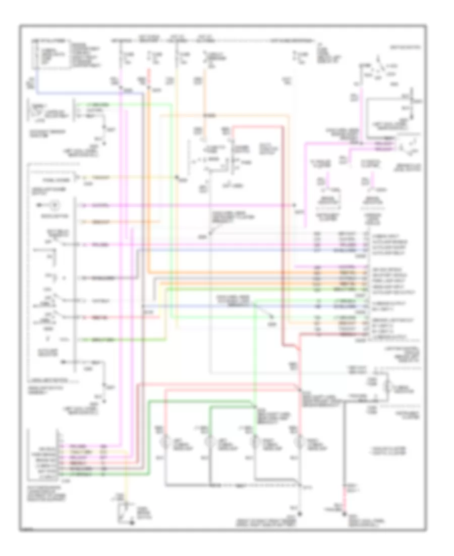
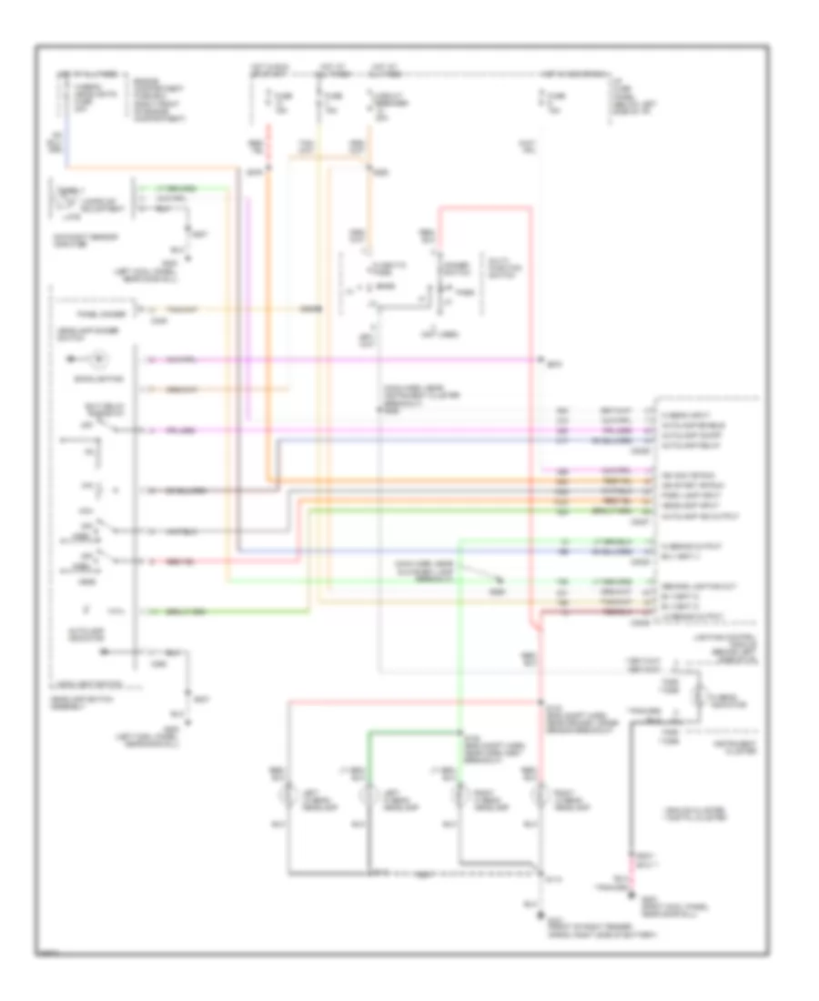
Exterior Lamps Wiring Diagram for Ford Crown Victoria S 1997
List of elements for Exterior Lamps Wiring Diagram for Ford Crown Victoria S 1997:
- (analog) (digital)
- (body harn, left front of trunk)
- (body harn, near brake switch breakout) s258
- (center rear of trunk, on support) g407
- (eng compt harn, near horn assembly breakout) s120
- (eng compt harn, near left front fender)
- (eng compt harn, near right front fender)
- (fuel tank harn, near g407 breakout) s419
- (left side of i/p) lighting control module (lcm)
- (main harn, near clock breakout)
- (main harn, near instrument cluster breakout)
- (rear harn, left rear of trunk)
- (rear harn, near trunk lid switch breakout) s412
- (rear harn, right rear of trunk)
- (right fender apron, right side of battery) g102
- B+ vbat 2
- B+ vbat 3
- Brake on/ off (boo) switch (top of brake pedal support)
- C2027
- C2029
- C250
- C250 c256
- C251 c256
- C256
- Circuit breaker 20a
- Clock
- Flasher power input
- Flasher power output
- Fuse 15a
- G201 (right cowl panel, near door sill)
- Grand marquis only
- Hazard switch
- Head
- Headlamp switch output
- Headlights system
- High mount stop lamp assembly
- Hot at all times
- Hot in run
- I/p fuse panel
- Instrument cluster
- Left
- Left corn- ering lamp
- Left front park lamp
- Left front side marker lamp
- Left rear park/ stop/ turn lamps
- Left turn indi- cator
- License lamps
- Lighting control module (lcm) (behind left side of i/p)
- Low beams output
- Main light switch
- Multi- function switch
- Nca
- Near trailer tow relays breakout)
- Off
- Park
- Parklamp output
- Parklamp switch input
- Right
- Right corn- ering lamp
- Right front park lamp
- Right front park/ turn/ side marker lamp
- Right front side marker lamp
- Right rear park/ stop/ turn lamps
- Right rear running lamp
- Right turn indi- cator
- S108
- S113
- S121
- S122
- S226
- S242
- S243 (main harn, near multi-function switch breakout)
- S257
- S257 or s210
- S262
- S263
- S285
- S301
- S400
- S401
- S402
- S403
- S409
- S413
- S414
- S416
- Trailer adapter
- Trailer exterior lamps relay
- Trailer left turn relay
- Trailer right turn relay
- Turn switch
- With trailer tow
Trailer/Camper Adapter Wiring Diagram for Ford Crown Victoria S 1997
List of elements for Trailer/Camper Adapter Wiring Diagram for Ford Crown Victoria S 1997:
- (center rear of trunk, on support)
- (center rear of trunk, on support) g407
- (fuel tank harn, near g400 breakout) s419
- (fuel tank harn, near trailer relays breakout) s418
- (left side of i/p) lighting control module (lcm)
- Battery charging wire
- Brake on/off & right turn signal output
- Brake on/off or left turn signal output
- Brake on/off switch
- C2029
- Electric brake feed
- Engine compart- ment fuse box
- Engine compartment fuse box
- Fuse 15a
- G407
- Hot at all times
- Hot in run
- I/p fuse panel
- Left turn signal & stop lamps
- Multi- function switch
- Multi-function switch breakout)
- Parklamp output
- Rear exterior lamps
- Red
- Right turn signal & stop lamps
- S226
- S265
- S402
- S404
- S409 (body harn, left front of trunk)
- S425
- Tail lamps
- Tlr brakes fuse 30a
- Tlr tow fuse 20a
- Tlr tow fuse 40a
- Trailer battery charging relay (left side of trunk)
- Trailer electronic brake control unit
- Trailer exterior lamps relay (left side of trunk)
- Trailer ground wire
- Trailer left turn relay (left side of trunk)
- Trailer right turn relay (left side of trunk)
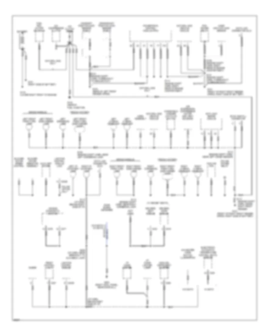
GROUND DISTRIBUTION
Ground Distribution Wiring Diagram (1 of 3) for Ford Crown Victoria S 1997
List of elements for Ground Distribution Wiring Diagram (1 of 3) for Ford Crown Victoria S 1997:
- (analog) instrument cluster
- (engine compt harn, inside right front fender)
- (i/p harn, behind right side of i/p) s204
- (not used)
- A/c clutch diode
- A/c compressor clutch
- A/c-heater mode switch illumination
- Air bag diagnostic monitor
- Air suspension compressor motor and vent solenoid
- Anti-lock brake module
- Auxiliary power
- Battery
- Blower motor resistor assembly
- Blower motor speed control
- C2026
- C2029
- C228
- C250
- C257
- C276
- C277
- C303
- C519
- Camshaft position (cmp) sensor shield
- Clock
- Cooling fan
- Crankshaft position (ckp) sensor shield
- Crown victoria
- Data link connector (dlc)
- Door blend actuator
- Driver's door module
- Driver's seat module
- Electronic automatic temperature control (eatc) module
- Evac and fill connector
- Front control unit
- Fuel rail cutoff solenoid
- G101 (front of right front fender apron, right side of battery)
- G101 (right side of battery)
- G104 (rear of left front fender apron)
- G119 (lower right front of engine)
- G134 (near #1 fuel injector)
- G203 (right cowl panel, near door sill)
- Grand marquis
- Horn assembly
- I/p cigar lighter
- I/p cigar lighter lamp
- Left cornering lamp
- Left front park/turn lamp
- Left front park/turn/ side marker lamp
- Left front side marker lamp
- Left hi beam headlamp
- Left i/p courtesy lamp
- Left lo beam headlamp
- Lighting control module
- Lighting control module (lcm)
- Mass air flow (maf) sensor
- Natural gas only
- Natural gas vehicle module
- Pcm power relay
- Police option only
- Police power relay
- Powertrain control module (pcm)
- Right cornering lamp
- Right front park/turn lamp
- Right front park/turn/ side marker lamp
- Right front side marker lamp
- Right hi beam headlamp
- Right i/p courtesy lamp
- Right lo beam headlamp
- S108 (engine compt harn, near left cornering lamp)
- S112 (engine compt harn, near left crash sensor)
- S112 (engine compt harn, near right cornering lamp)
- S112 (i/p harn, behind right side of i/p)
- S113
- S114 (engine compt harn, right rear of engine compartment)
- S141 (engine compt harn, in breakout to ground g101)
- S206 (i/p harn, near breakout to glovebox lamp)
- W/ eatc
- W/ memory seats
- W/o eatc
- Windshield washer low fluid switch
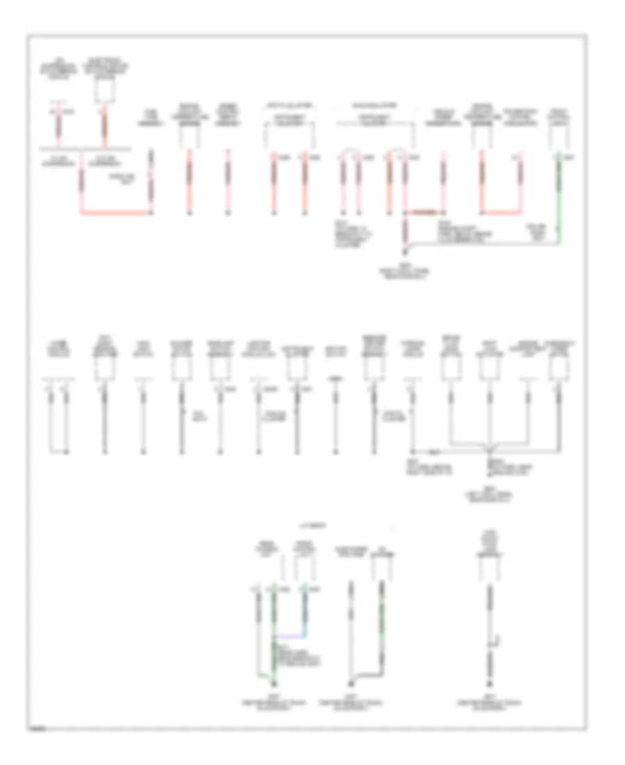
Ground Distribution Wiring Diagram (2 of 3) for Ford Crown Victoria S 1997
List of elements for Ground Distribution Wiring Diagram (2 of 3) for Ford Crown Victoria S 1997:
- 48 (bare)
- Air suspension/ evo steering module
- Analog cluster
- Blower motor switch
- Brake fluid level switch
- C2029
- C216
- C249
- C250
- C251
- C255
- C256
- C257
- C452
- Cd changer
- Day/ night sensor/ amplifier
- Digital cluster
- Electronic variable orifice (evo) steering module
- Engine compartment lamp
- Engine coolant temperature sensor
- Front control unit
- Fuel tank assembly
- G200 (left cowl panel, near door sill)
- G203 (right cowl panel, near door sill)
- G407 (center rear of trunk, on support)
- Gasoline only
- Gnd
- Headlamp switch assembly
- High mount stop lamp assembly
- Ignition switch
- Instrument cluster
- Lighting control module (lcm)
- Lux radio
- Main light switch
- Message center switch assembly
- Midline radio only
- Nca
- Powertrain control module (pcm)
- Rear chassis unit
- S105 (engine compt harn, below brake fluid reservoir)
- S207 (i/p harn, behind right side of i/p)
- S210 (i/p harn, in breakout to instrument cluster)
- Shift lock actuator
- Speed control servo assembly
- Subwoofer amplifier
- Vehicle speed sensor (vss)
- W/ air suspension
- W/o air suspension
- W/o eatc
- Warning lamps module
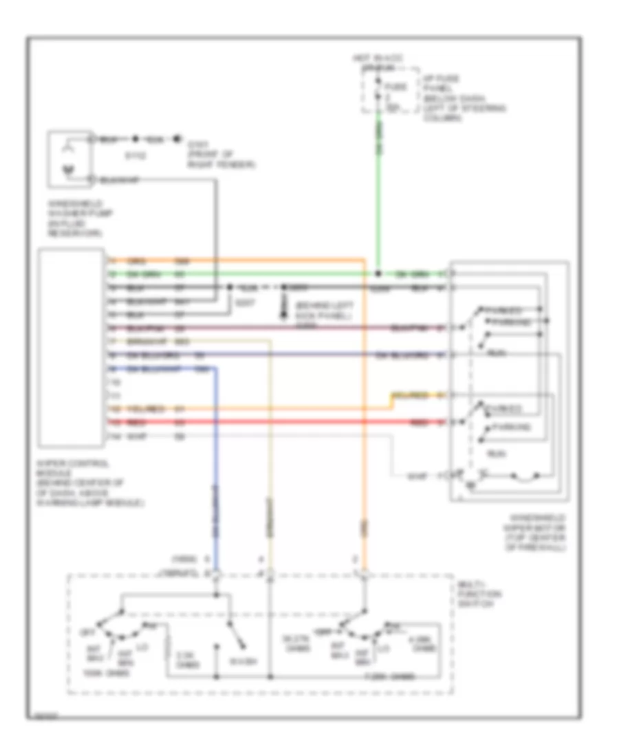
- Windshield wiper motor
- Wiper control module
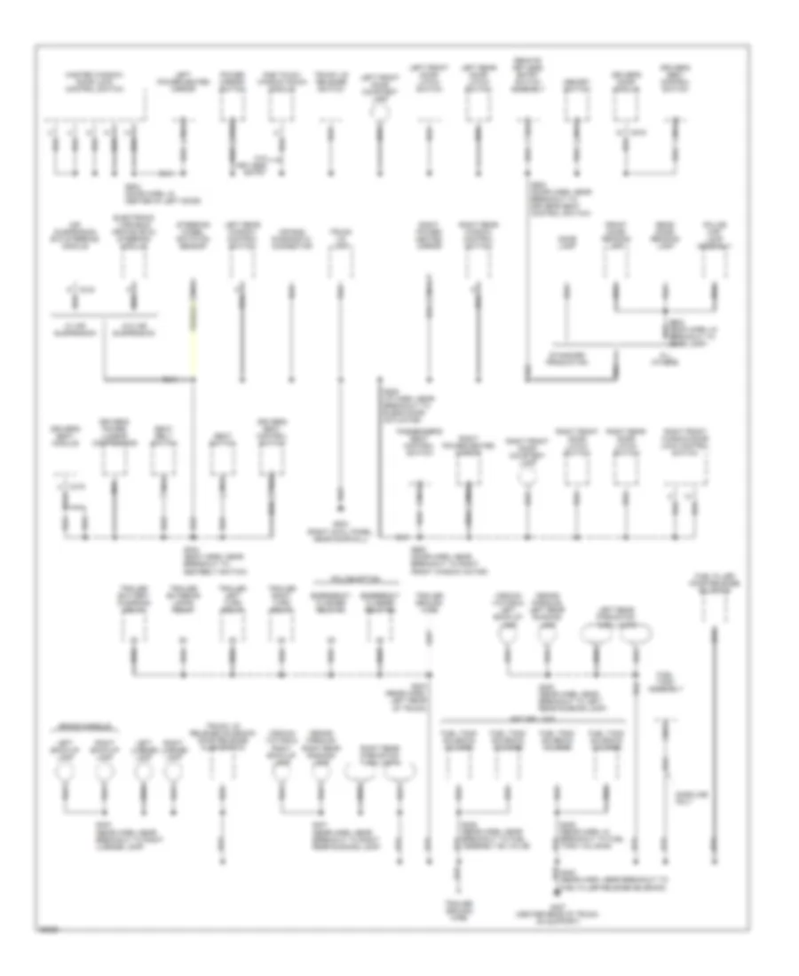
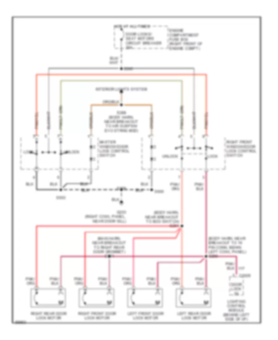
Ground Distribution Wiring Diagram (3 of 3) for Ford Crown Victoria S 1997
List of elements for Ground Distribution Wiring Diagram (3 of 3) for Ford Crown Victoria S 1997:
- (crown victoria) left back-up lamp
- (crown victoria) right back-up lamp
- (grand marquis) left rear running lamp
- (grand marquis) right rear running lamp
- Air bag diagnostic connector
- Air suspension evo steering module
- All others
- C216
- C319
- C519
- Dome lamp
- Driver's door module
- Driver's power lumbar compressor
- Driver's seat control switch
- Driver's seat module
- Electronic variable orifice (evo) steering module
- Emergency flasher relay #1
- Emergency flasher relay #2
- Front dome/ reading lamp
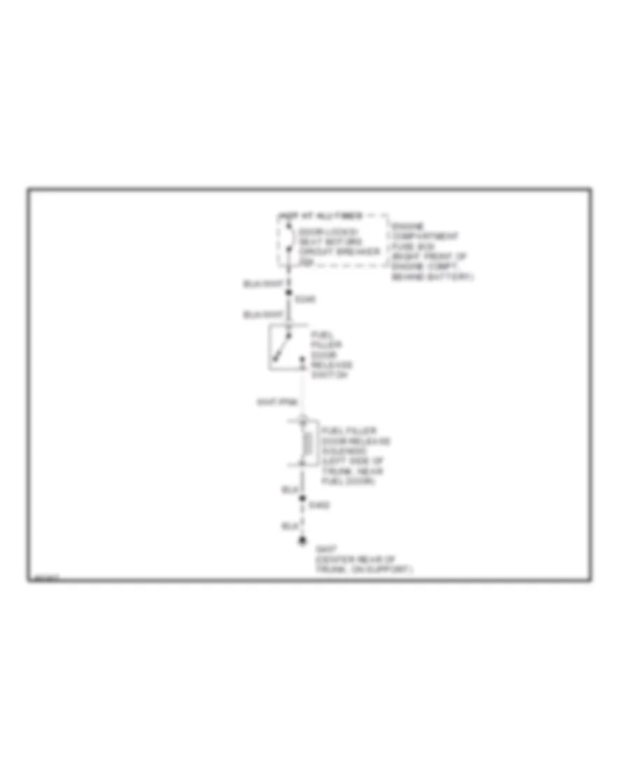
- Fuel filler door release solenoid
- Fuel filler release solenoid)
- Fuel tank assembly
- Fuel tank solenoid valve #1
- Fuel tank solenoid valve #2
- Fuel tank solenoid valve #3
- Fuel tank solenoid valve #4
- G203 (right cowl panel, near door sill)
- G407 (center rear of trunk, on support)
- Gasoline only
- Grand marquis
- Left back-up lamp
- Left front door courtesy lamp
- Left front door latch switch
- Left license lamp
- Left power/heated mirror
- Left rear door latch switch
- Left rear park/stop/ turn lamps
- Left rear window control switch
- Master window/ door lock control switch
- Memory switch
- Natural gas
- Nca
- One touch window down module
- Passenger's seat control switch
- Police map lamp assembly
- Police option
- Power mirror switch
- Rear dome/ reading lamp
- Remote keyless entry switch assembly
- Right back-up lamp
- Right front door courtesy lamp
- Right front door latch switch
- Right front window/door lock control switch
- Right license lamp
- Right power/ heated mirror
- Right power/heated mirror
- Right rear door latch switch
- Right rear park/stop/ turn lamps
- Right rear window control switch
- S208 (i/p harn, near breakout to blend door actuator)
- S304 (body harn, near breakout to seatbelt switch)
- S400 (rear harn, near breakout to left rear running lamp)
- S401 (rear harn, near breakout to right rear running lamp)
- S403 (rear harn, near breakout to right license lamp)
- S404 (rear harn, left rear of trunk)
- S405 (rear harn, in breakout to fuel tank valve #4)
- S428 (rear harn, near breakout to fuel assembly #2 valve)
- S500 (door harn, near breakout to driver's seat control switch)
- S503 (door harn, in center of left door)
- S600 (door harn, near breakout to right front window motor)
- Seat belt switch
- Seat switch
- Standard production
- Steering wheel rotation sensor
- Trailer battery charging relay
- Trailer exterior lamps relay
- Trailer ground wire
- Trailer left turn relay
- Trailer right turn relay
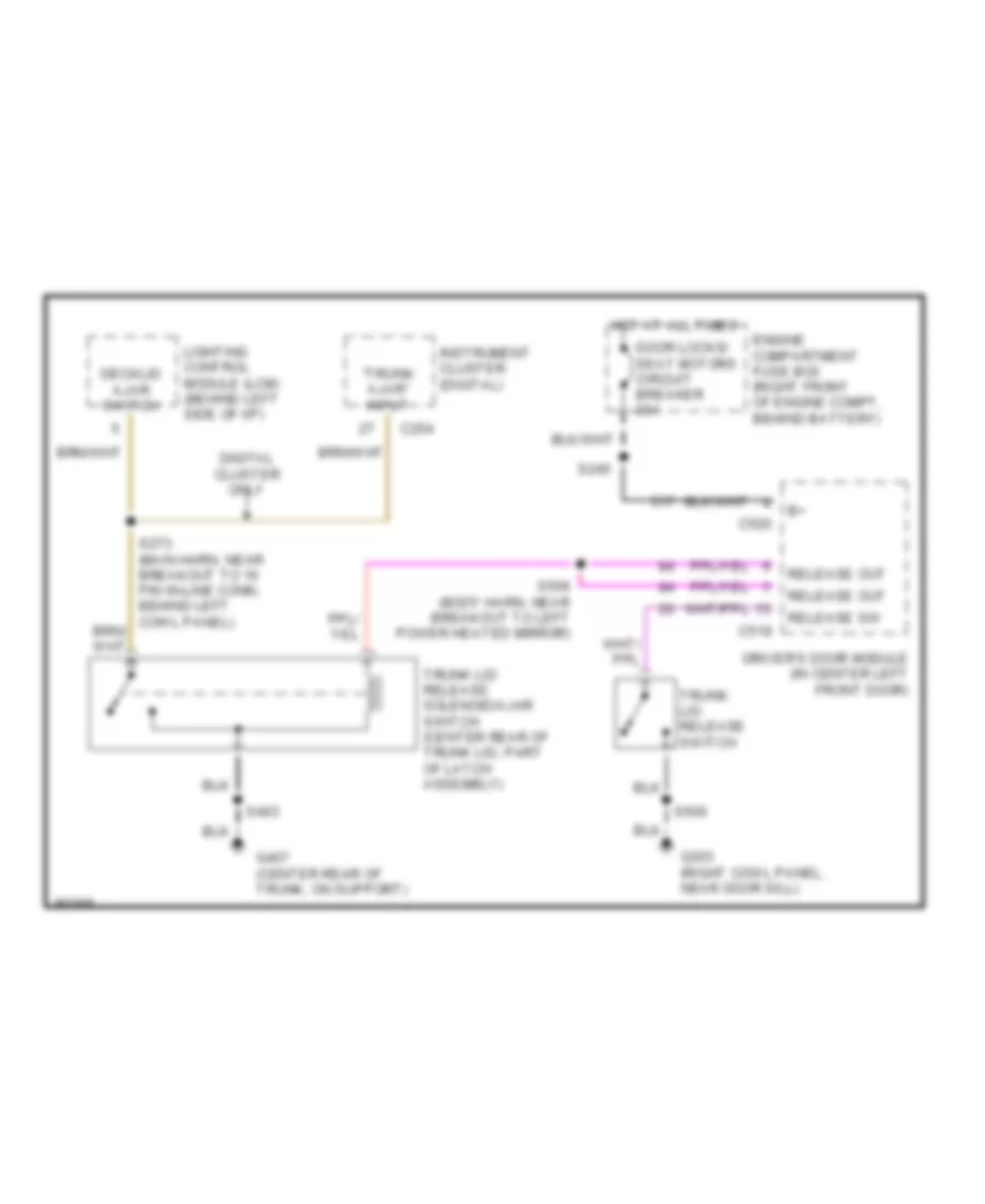
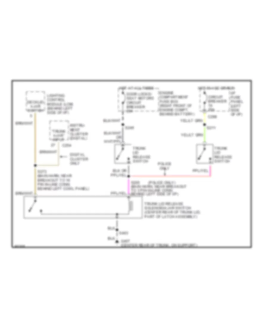
- Trunk lid lamp
- Trunk lid release solenoid/ door release ajar switch
- Trunk lid release switch
- W/ air suspension
- W/o air suspension
- W/o keyless entry
HEADLIGHTS
Headlamps Wiring Diagram, with DRL for Ford Crown Victoria S 1997
List of elements for Headlamps Wiring Diagram, with DRL for Ford Crown Victoria S 1997:
- "lamps on" adjustment
- (main harn, near engine compt grommet) s248
- (main harn, near glove box lamp breakout)
- (main harn, near instrument cluster breakout)
- (not used)
- * analog cluster
- ** digital cluster
- **c256
- *c250
- Acc
- Aut0lamp enable
- Autolamp delay
- Autolamp ind output
- Autolamp indicator
- Autolamp on/off
- B(+) vbat 4
- B+ (vbat 2)
- B+ (vbat 3)
- Backlighting
- Bat pwr
- Brake fluid level switch
- Brake ind
- Brake indicator
- C180
- C2004
- C2026
- C2027
- C2028
- C2029
- C249
- C250
- C262
- Circuit breaker 20a
- Day/night sensor amplifier
- Daytime running lamps module (on front of upper radiator support)
- Demand lighting out
- Dimmer switch
- Early
- Engine compartment fuse box (right front of engine compartment)
- Exit delay rheostat
- Flash-to- pass
- Fuse 15a
- G101 (front of right front fender apron, right side of battery)
- G200 (left cowl panel, near door sill)
- G203 (right cowl panel, near door sill)
- Gnd
- Head
- Headlamp dimmer switch
- Headlamp input
- Headlamp switch assembly
- Hi beam indicator
- Hi beams output
- Hi input
- Hi-beam headlights fuse 20a
- Hi-beam input
- Hot at all times
- Hot in acc or or run
- Hot in run
- Hot in run or start
- I/p fuse panel (below left side of i/p)
- Ign (run)
- Ign acc or run
- Ign start or run
- Ignition switch
- Instrument cluster
- Late
- Left hi beam headlamp
- Left lo beam headlamp
- Lighting control module (behind left side of i/p)
- Lo beam in
- Lo beams output
- Lock
- Low
- Main light switch
- Max
- Min
- Multi- function switch
- Off
- Panel dimmer
- Park
- Park brake
- Park brake switch
- Park lamp input
- Pass
- Right hi beam headlamp
- Right lo beam headlamp
- Run
- S112
- S113
- S138 (eng compt harn, near horn assy breakout)
- S140 (eng compt harn, near primary crash sensor breakout)
- S149
- S203
- S204 *
- S207
- S210 **
- S226
- S262
- S276
- S278
- S280
- S285
- S290
- Start
- W/ analog cluster
- W/ digital cluster
- Warning lamps module
Headlamps Wiring Diagram, without DRL for Ford Crown Victoria S 1997
List of elements for Headlamps Wiring Diagram, without DRL for Ford Crown Victoria S 1997:
- "lamps on" adjustment
- (main harn, near glove box lamp breakout)
- (main harn, near instrument cluster breakout) s280
- (not used)
- * analog cluster ** digital cluster
- **c256
- *c250
- Aut0lamp enable
- Autolamp delay
- Autolamp ind output
- Autolamp indicator
- Autolamp on/off
- B(+) vbat 4
- B+ (vbat 2)
- B+ (vbat 3)
- Backlighting
- C2026
- C2027
- C2028
- C2029
- C249
- C262
- Circuit breaker 20a
- Day/night sensor amplifier
- Demand lighting out
- Dimmer switch
- Early
- Engine compartment fuse box (right front of engine compartment)
- Exit delay rheostat
- Flash-to- pass
- Fuse 15a
- G101 (front of right fender apron, right side of battery)
- G200 (left cowl panel, near door sill)
- G203 (right cowl panel, near door sill)
- Head
- Headlamp dimmer switch
- Headlamp input
- Headlamp switch assembly
- Hi beam indicator
- Hi beam input
- Hi beams output
- Hi-beam headlights fuse 20a
- Hot at all times
- Hot in acc or run
- Hot in run or start
- I/p fuse panel (below left side of i/p)
- Ign acc or run
- Ign start or run
- Instrument cluster
- Late
- Left hi beam headlamp
- Left lo beam headlamp
- Lighting control module (behind left side of i/p)
- Lo beams output
- Main light switch
- Max
- Min
- Multi- function switch
- Off
- Panel dimmer
- Park
- Park lamp input
- Pass
- Right hi beam headlamp
- Right lo beam headlamp
- S112
- S113
- S138 (eng compt harn, near horn assy breakout)
- S140 (eng compt harn, near primary crash sensor breakout)
- S204 *
- S207
- S210 **
- S262
- S276
- S278
- S285
- S290
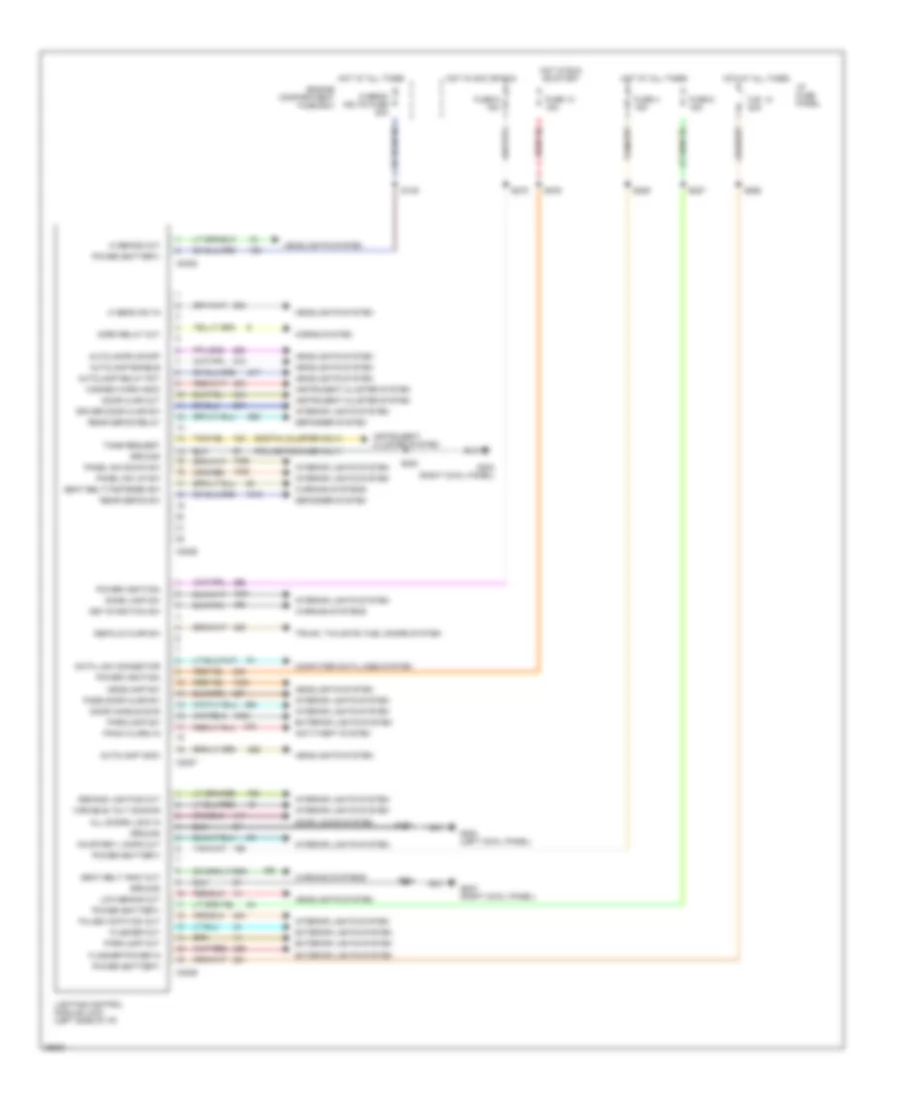
Lighting Control Module Wiring Diagram for Ford Crown Victoria S 1997
List of elements for Lighting Control Module Wiring Diagram for Ford Crown Victoria S 1997:
- (digital cluster only)
- (police package only)
- All doors lock in
- Anti-theft system
- Autolamp delay pot
- Autolamp enable
- Autolamp indic
- Autolamps on/off
- C.b. 12 20a
- C2026
- C2027
- C2028
- C2029
- Computer data lines system
- Courtesy lamps out
- Data link connector
- Decklid ajar sw
- Defogger system
- Demand lighting out
- Dome lamp sw
- Door ajar out
- Door handle sws
- Door locks system
- Driver door ajar sw
- Engine compartment fuse box
- Exterior lights system
- Flasher out
- Flasher power in
- Fuse 13 15a
- Fuse 4 15a
- Fuse 6 15a
- Fuse 8 15a
- G200 (left cowl panel)
- G203 (right cowl panel)
- Ground
- Hazard warn indic
- Headlamp sw
- Headlights system
- Hi beam sw in
- Hi beams out
- Hi-beam hdlts fuse 20a
- Horn relay out
- Horns system
- Hot at all times
- Hot in acc or run
- Hot in run or start
- I/p fuse panel
- Instrument cluster system
- Interior lights system
- Key-in-ignition sw
- Lighting control module (lcm) (left side of i/p)
- Low beams out
- Panel dim down sw
- Panel dim up sw
- Panic alarm in
- Parklamp out
- Parklamp sw
- Pass door ajar sw
- Power (battery)
- Power (ignition)
- Pulse width dim out
- Rear defog relay
- Rear defog sw
- S149
- S200
- S204
- S207
- S227
- S262
- S276
- S278
- S285
- Seat belt fastened sw
- Seat belt indic out
- Tone request
- Trunk, tailgate, fuel doors system
- Variable volt dimming
- Warning systems
HORN
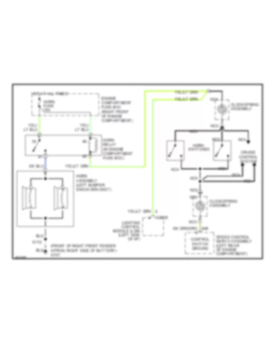
Horn Wiring Diagram for Ford Crown Victoria S 1997
List of elements for Horn Wiring Diagram for Ford Crown Victoria S 1997:
-
- (front of right front fender apron, right side of battery) g101
- C2026
- Clockspring assembly
- Control switch ground
- Cruise control system
- Engine compartment fuse box (right front of engine compartment)
- Horn
- Horn assembly (left bumper shock bracket)
- Horn fuse 15a
- Horn relay (in engine compartment fuse box)
- Hot at all times
- Lighting control module (lcm) (left side of i/p)
- Nca
- S112
- Speed control servo assembly (left rear of engine compartment)
- Switches
INSTRUMENT CLUSTER
Analog Cluster Wiring Diagram for Ford Crown Victoria S 1997
List of elements for Analog Cluster Wiring Diagram for Ford Crown Victoria S 1997:
- "air bag"
- "anti-lock"
- (above glove box)
- (above oil
- (behind left cowl
- (brake fluid
- (check engine)
- (front center of upper
- (left front upper
- (left rear of
- (left side
- (left side of i/p)
- (left side of instrument
- (main harn,
- (main harn, near
- (multi-function switch)
- (qty. 6)
- (rear of
- (right cowl panel,
- (right front of
- (right side of
- (top of park
- (top right front
- 10a
- 15a
- 30a
- Acc
- Air
- Air suspension
- Air suspension/evo steering
- Airbag diagnostic monitor
- Airbag indicator
- Anti-lock brake module
- Anti-slosh
- Assembly
- At all
- Belts indicator
- Brake
- Brake assembly)
- Brake fluid
- Breakout to airbag
- C2029
- C215
- C250
- C251
- C276
- C459
- Charge
- Compartment
- Control
- Coolant
- Daytime running
- Diag conn)
- Dimming output
- Drl
- Drl disable
- Electronic
- Engine
- Engine compartment)
- Engine coolant
- Engine oil
- Engine oil pressure
- Exterior lights system
- Fasten
- Filter)
- Fuel
- Fuel tank)
- Fuse
- Fuse box
- G200
- G203
- Gauge
- Generator/
- Gnd
- Guage
- Headlights system
- Hi beam
- Hot
- Hot in
- I/p
- Ignition switch
- Illumination lamps
- In run
- Indicator
- Indicator control
- Indicator output
- Instrument cluster
- Lamp (tcil)
- Lamps (drl) module
- Left turn
- Level switch
- Lighting control module
- Lock
- Low
- Low fuel
- Malfunction
- Mil output
- Module
- Near door sill)
- Near grommet
- Normal
- Odometer
- Of engine)
- Of i/p)
- Off
- Ohms
- Or run
- Panel
- Panel, near door sill)
- Panel, on left
- Park
- Powertrain control module (pcm)
- Pressure
- Pump/
- Radiator support)
- Regulator
- Reservoir)
- Right turn
- Run
- S105
- S144
- S203
- S204
- S210
- S231
- S248
- S276
- S300
- Sender
- Sensor
- Side of safety wall)
- Speed
- Speedo
- Speedometer/
- Start
- Suspension
- Suspn
- Switch
- Tank
- Tcil
- Temperature
- Test connector
- Times
- To eng compt)
- Transmission
- Transmission)
- Trunk)
- Vehicle
- Voltage
- Voltmeter
- W/o
Analog Cluster Wiring Diagram, with Natural Gas for Ford Crown Victoria S 1997
List of elements for Analog Cluster Wiring Diagram, with Natural Gas for Ford Crown Victoria S 1997:
- "air bag"
- "anti-lock"
- (above glove box)
- (above oil
- (behind left cowl
- (body harn, near
- (brake fluid
- (check engine)
- (front center of upper
- (front of
- (left front upper
- (left rear of
- (left side
- (left side of i/p)
- (left side of instrument
- (main harn,
- (main harn, near
- (multi-function switch)
- (qty. 6)
- (right cowl panel,
- (right front of
- (right side of
- (top of park
- (top right front
- 10a
- 30a
- Acc
- Air
- Air suspension
- Air suspension/evo steering
- Airbag diagnostic monitor
- Airbag indicator
- Anti-lock brake module
- Anti-slosh
- Belts indicator
- Brake
- Brake assembly)
- Brake fluid
- Breakout to
- Breakout to airbag
- C2029
- C215
- C250
- C251
- C276
- C459
- Charge
- Cluster
- Compartment
- Compartment)
- Control
- Coolant
- Daytime running
- Diag conn)
- Dimming output
- Drl
- Drl disable
- Electronic
- Engine
- Engine compartment)
- Engine coolant
- Engine oil
- Engine oil pressure
- Exterior lights system
- Fasten
- Filter)
- Fuel
- Fuse
- Fuse box
- G200
- G203
- Gas vehicle
- Gauge
- Generator/
- Gnd
- Ground
- Guage
- Headlights system
- Hi beam
- Hot at all times
- Hot in run
- I/p
- Ignition switch
- Illumination lamps
- Indicator
- Indicator control
- Indicator output
- Inst cluster)
- Instrument cluster
- Lamp (tcil)
- Lamps (drl) module
- Left turn
- Level switch
- Lighting control module
- Lock
- Low
- Low fuel
- Malfunction
- Mil output
- Module
- Natural
- Near door sill)
- Near grommet
- Normal
- Odometer
- Of engine)
- Of i/p)
- Off
- Ohms
- Panel
- Panel, near door sill)
- Panel, on left
- Park
- Power
- Powertrain control module (pcm)
- Pressure
- Pump/
- Radiator support)
- Regulator
- Reservoir)
- Right turn
- Run
- S105
- S144
- S203
- S204
- S210
- S231
- S248
- S299
- S300
- Sender
- Sensor
- Side of safety wall)
- Signal
- Speed
- Speedo
- Speedometer/
- Start
- Suspension
- Suspn
- Switch
- Tcil
- Temperature
- Test connector
- To eng compt)
- Transmission
- Transmission)
- Trunk)
- Vehicle
- Voltage
- Voltmeter
- W/o
Electronic Cluster Wiring Diagram (1 of 2) for Ford Crown Victoria S 1997
List of elements for Electronic Cluster Wiring Diagram (1 of 2) for Ford Crown Victoria S 1997:
- (above oil filter)
- (behind right
- (body harn, near
- (front of right front fender
- (in fluid reservoir)
- (left rear
- (left rear of
- (left side of safety wall)
- (main harn, near
- (rear of
- (right front cowl
- (right side of trunk)
- (top right
- 15a
- 17400 ohm
- 2670 ohm
- 7320 ohm
- Air bag
- Air susp in
- Air suspension
- Air suspension/
- Airbag diagnostic
- Airbag ind in
- All times
- Apron, right side of battery)
- Assembly
- Automatic
- Battery power
- Breakout to
- C215
- C227
- C254
- C255
- C256
- C276
- Charge ind in
- Cluster)
- Connector)
- Control (eatc)
- Coolant temp sens in
- Deck lid open
- Diagnostic
- Dim display in
- Door ajar in
- Door sill)
- E/m
- Electronic
- Engine compartment)
- Engine coolant temperature
- Engine oil
- English/metric
- Evo steering module
- Exterior lights system
- Fasten belts in
- Front of engine)
- Fuel
- Fuel flow rate in
- Fuel level in
- Fuel tank)
- Fuse
- G101
- G203
- Headlights system
- Hi beam in
- Hot at
- Hot in run
- I/p
- Ind
- Instrument cluster
- Interior
- Interior lights system
- Left turn signal
- Lights
- Low fluid switch
- Low washer fluid in
- Malfunction ind
- Message center switch assembly
- Module
- Monitor
- Of transmission)
- Oil pres ind in
- Out
- Output
- Panel
- Panel, near
- Power ground
- Powertrain control module
- Pressure switch
- Prndl illum
- Red 506
- Reset
- Right turn signal
- S105
- S109
- S112
- S202
- S210
- S227
- S269
- S300
- Select
- Sens ground
- Sensor
- Servo assembly
- Side of i/p)
- Sound tone output
- Speed control
- Speed control in
- Switch assembly in
- Switched power
- Tank
- Temperature
- Test connector
- Trans ctrl ind lt
- Vehicle speed
- Vehicle speed in +
- Windshield washer
Electronic Cluster Wiring Diagram (2 of 2) for Ford Crown Victoria S 1997
List of elements for Electronic Cluster Wiring Diagram (2 of 2) for Ford Crown Victoria S 1997:
- (above glove box)
- (behind right
- (body harn, at
- (body harn, near
- (center rear
- (left front door)
- (left side of i/p)
- (main harn,
- (main harn, near
- (part of
- (right cowl panel,
- 10a
- A pillar)
- Air suspension
- Airbag diagnostic
- Ajar
- Ajar lamp output
- Behind left
- Breakout to
- C2026
- C2027
- C2029
- C216
- C518
- Center of right
- Closed
- Connector)
- Cowl panel,
- Decklid jar
- Door
- Door ajar
- Driver's ajar switch
- Driver's door
- Evo steering module
- Front
- Fuse
- G203
- G407
- Generator/voltage regulator
- Hot
- I/p
- In run
- Input
- Kick panel)
- Latch
- Latch assembly)
- Left
- Lid
- Lighting control module
- Lighting ctrl
- Module
- Module)
- Near door sill)
- Of trunk
- On support)
- Panel
- Pass. ajar switch
- Rear
- Right
- S231
- S257
- S268
- S273
- S277
- S304
- S403
- S500
- S600
- Seat belt
- Seatbelt ind out
- Seatbelt switch
- Solenoid ajar switch
- Switch
- Tone request
- Trunk lid release
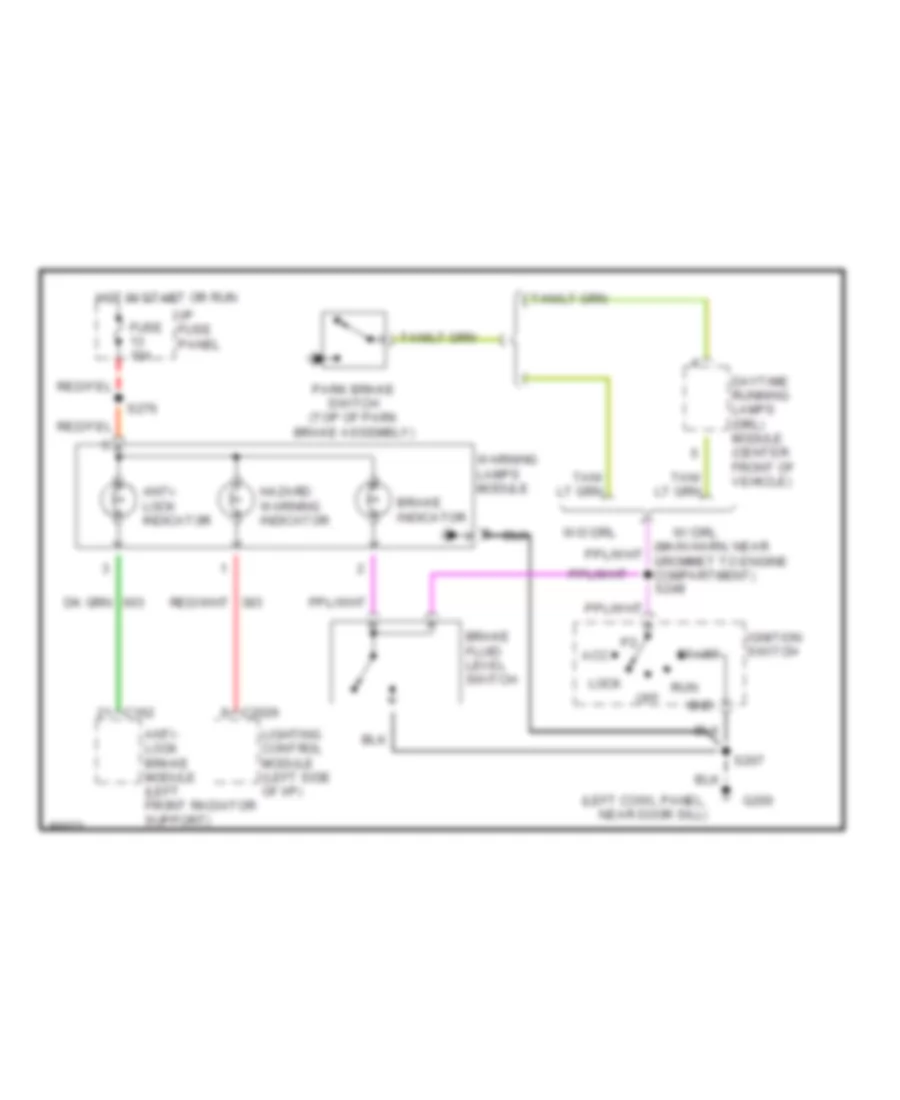
Warning Lights Wiring Diagram for Ford Crown Victoria S 1997
List of elements for Warning Lights Wiring Diagram for Ford Crown Victoria S 1997:
- (left cowl panel, near door sill)
- Acc
- Anti- lock brake module (left front radiator support)
- Anti- lock indicator
- Brake fluid level switch
- Brake indicator
- C162
- C2026
- Daytime running lamps (drl) module (center front of vehicle)
- Fuse 15a
- G200
- Gnd
- Hazard warning indicator
- Hot in start or run
- I/p fuse panel
- Ignition switch
- Lighting control module (left side of i/p)
- Lock
- Off
- Park brake switch (top of park brake assembly)
- Run
- S207
- S276
- Start
- W/ drl
- W/o drl
- Warning lamps module
INTERIOR LIGHTS
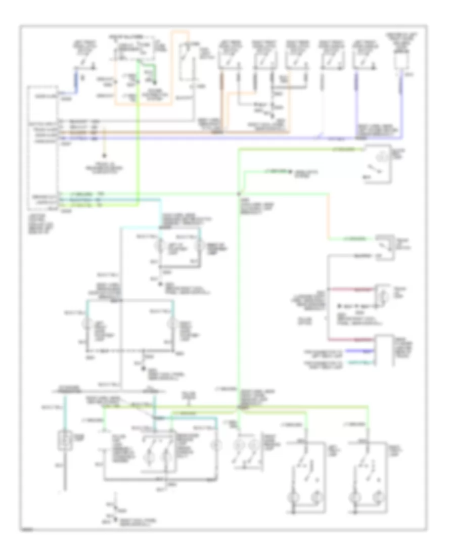
Courtesy Lamps Wiring Diagram for Ford Crown Victoria S 1997
List of elements for Courtesy Lamps Wiring Diagram for Ford Crown Victoria S 1997:
- (body harn, near blend door actuator breakout) s237
- (body harn, near left power heated mirror breakout) s505
- (body harn, near right "a" pillar) s259
- (center of left front door) driver's door module
- (main harn, near message center switch assembly breakout) s236
- (right cowl panel, near door sill)
- (roof harn, near center of right "a" pillar)
- (roof harn, near front dome/ reading lamp breakout) s900
- All others
- B (+)
- C2026
- C2027
- C2029
- C262
- C518
- Circuit breaker 20a
- Demand out
- Dome lamp
- Door ajar
- For connection to left deck lamp
- For connection to right deck lamp
- Front dome/ reading lamp
- Fuse 15a
- G203
- G203 (behind right cowl panel, near door sill)
- G203 (right cowl panel, near door sill)
- Glove box lamp
- Handle sw
- Headlights system
- Hot at all times
- I/p fuse panel
- Lamps out
- Left front door courtesy lamp
- Left front door handle switch
- Left front door latch switch
- Left i/p courtesy lamp
- Left rear door latch switch
- Left vanity lamp
- Lighting control module (lcm) (behind left side of i/p)
- Main light switch
- Nca
- Police map lamp assembly (center of windshield header)
- Police option
- Power distribution system
- Rear dome/ reading lamp (grand marquis only)
- Rear flasher (center rear of trunk)
- Right front door courtesy lamp
- Right front door handle switch
- Right front door latch switch
- Right i/p right i/p courtesy courtesy lamp lamp
- Right rear door latch switch
- Right vanity lamp
- S200
- S208
- S227
- S262
- S290 (main harn, near glove box lamp breakout)
- S431 (luggage compt harn, near right rear speaker breakout)
- S500
- S600
- S901
- S902
- Standard production
- Switch input
- Trunk ajar
- Trunk lid lamp
- Trunk lid release solenoid/ ajar switch
- Trunk lid switch
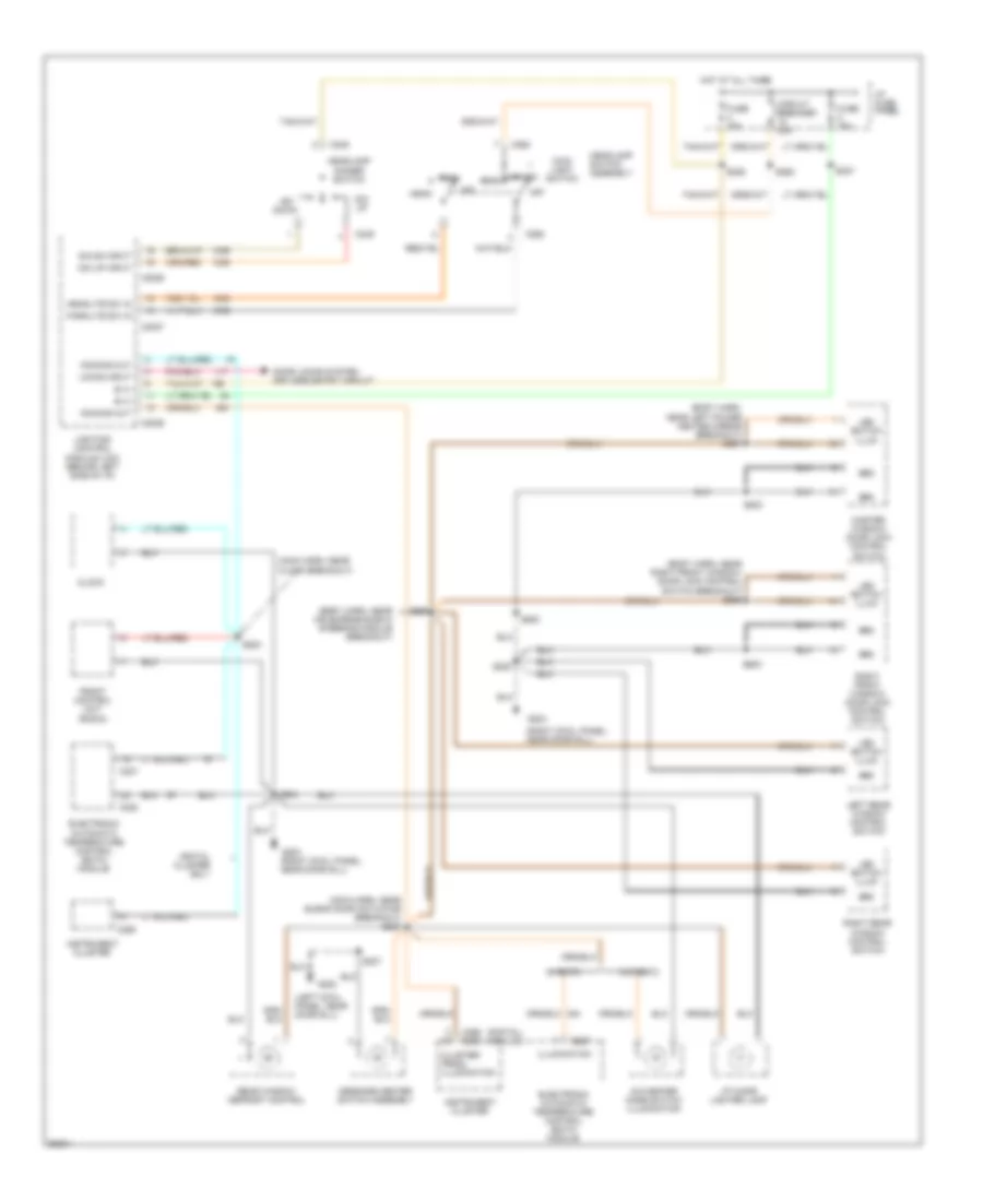
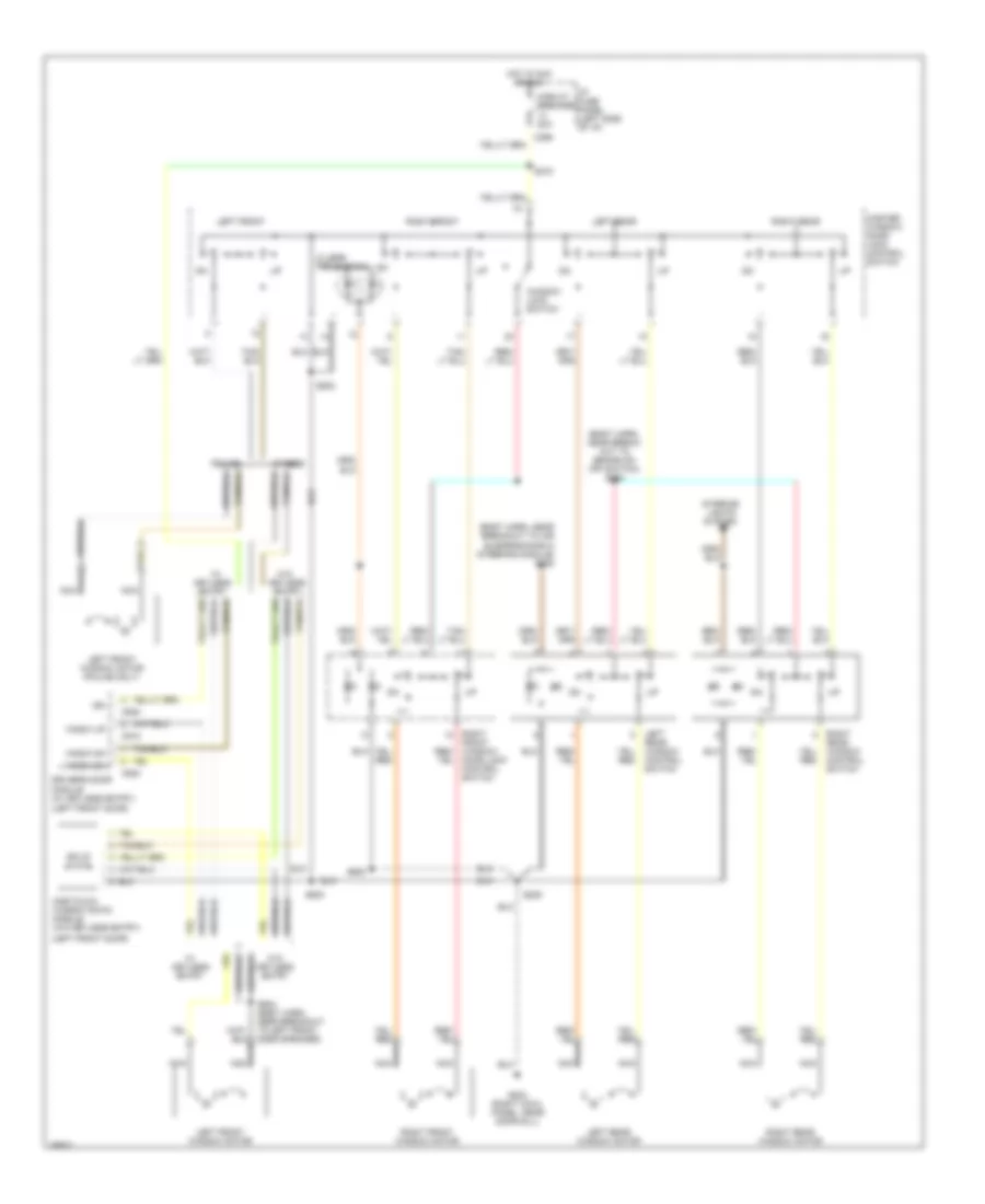
Instrument Illumination Wiring Diagram for Ford Crown Victoria S 1997
List of elements for Instrument Illumination Wiring Diagram for Ford Crown Victoria S 1997:
- (body harn, near air supension/evo steering module breakout)
- (body harn, near left power heated mirror breakout) s507
- (body harn, near right front window/ door lock control switch breakout) s289
- (digital) (analog)
- (left cowl panel, near door sill)
- (main harn, near blend door actuator breakout) s287
- (main harn, near clock breakout)
- (right cowl panel, near door sill)
- A/c-heater mode switch illumination
- B (+)
- C2026
- C2027
- C2029
- C227
- C228
- C249
- C255
- C256 c250
- C262
- Circuit breaker 20a
- Clock
- Cluster/ prndl illumination
- Digital cluster only
- Dim dn input
- Dim down
- Dim up
- Dim up input
- Dimming out
- Door locks system keyless entry circuit
- Electronic automatic temperature control (eatc) module
- Front control unit (radio)
- Fuse 15a
- G200
- G203
- Grd
- Head
- Headlamp dimmer switch
- Headlamp switch assembly
- Headlite sw in
- Hot at all times
- I/p cigar lighter lamp
- I/p fuse panel
- Illumination
- Instrument cluster
- Led switch illum
- Left rear window control switch
- Lighting control module (lcm) (behind left side of i/p)
- Locks input
- Main light switch
- Master window/ door lock control switch
- Message center switch assembly
- Off
- Park
- Parklite sw in
- Rear window defrost control
- Right front window/ door lock control switch
- Right rear window control switch
- S204
- S207
- S208
- S227
- S262
- S285
- S288
- S500
- S503
- S523
- S600
- W/ eatc
- W/o eatc
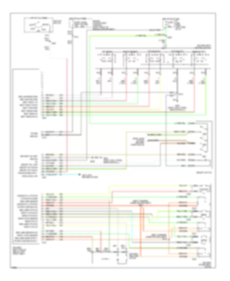
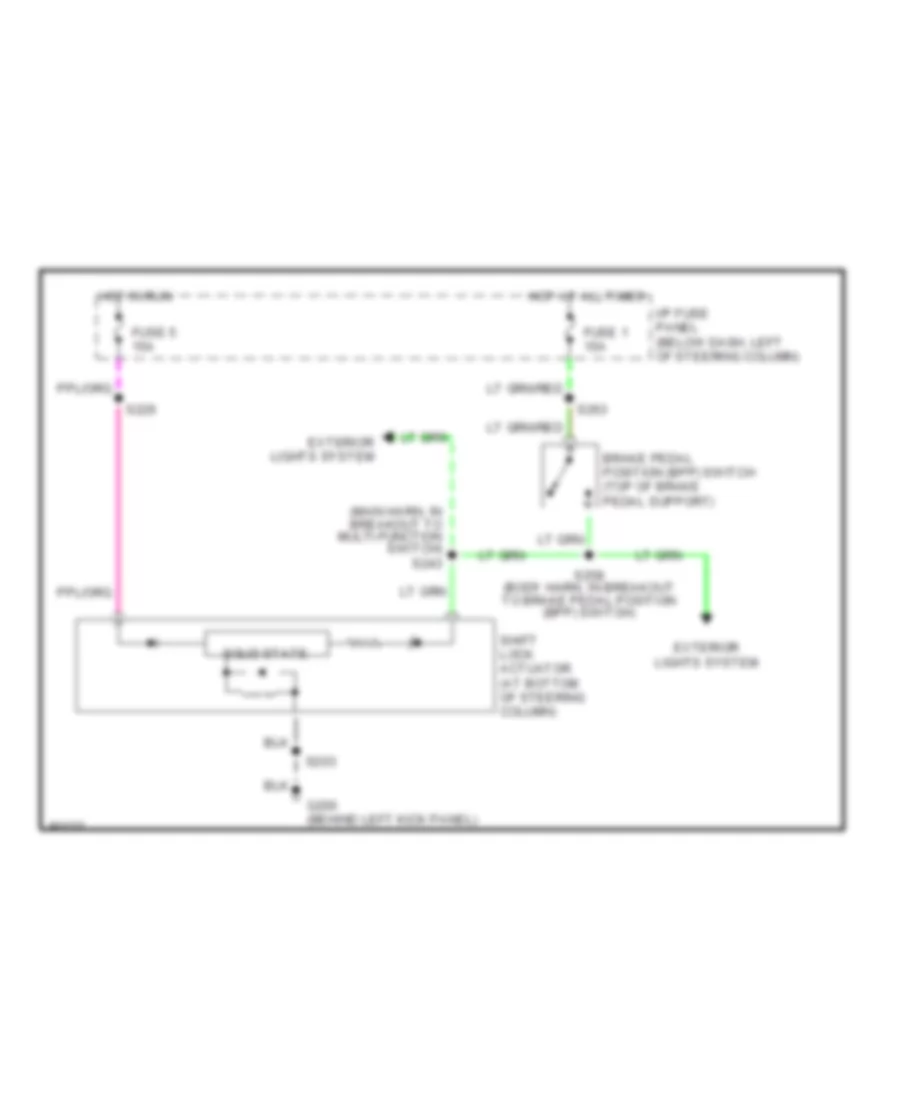
MEMORY SYSTEMS
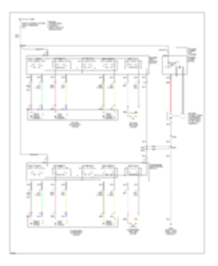
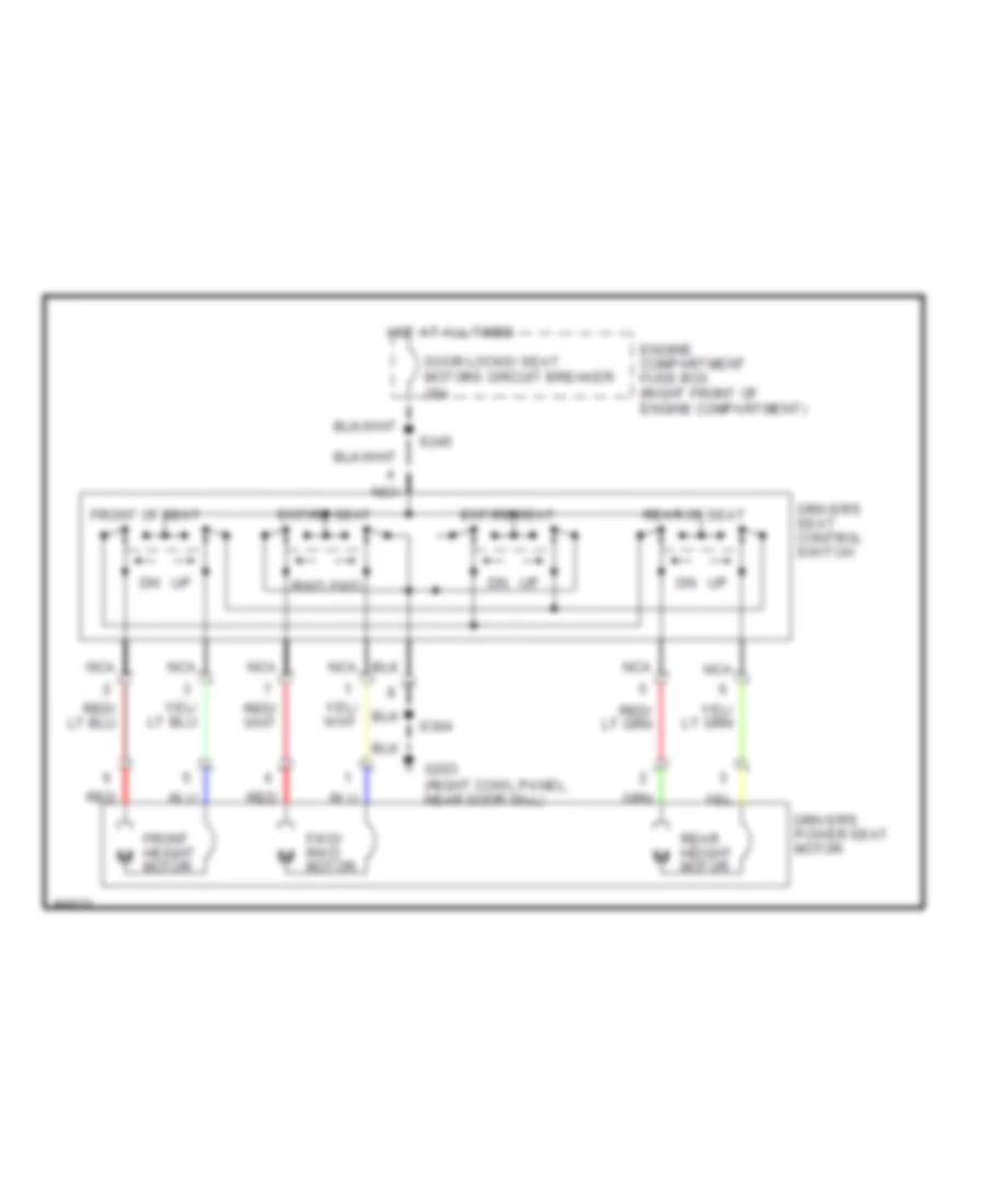
Memory System Wiring Diagrams for Ford Crown Victoria S 1997
List of elements for Memory System Wiring Diagrams for Ford Crown Victoria S 1997:
- (seat harness, under driver's seat) s314
- (seat harness, under driver's seat) s315
- 20a
- Acc
- Anti-lock brakes system
- C302
- C303
- C318
- C319
- C320
- C321
- C322
- C325
- Door locks system (driver's door module)
- Door locks/ seat motors c.b.
- Driver's power seat motor
- Driver's recliner motor
- Driver's seat control switch
- Driver's seat module (below left front seat)
- Engine compartment fuse box (right front of engine compartment)
- Entire seat
- Front
- Front mtr down
- Front mtr up
- Front of seat
- Front up/dn sensor
- Fuse 15a
- Fwd
- Fwd/rwd
- G203 (right cowl panel, near door sill)
- Ground
- Horizontal mtr fwd
- Horizontal mtr rwd
- Hot at all times
- I/p fuse panel (left side of i/p)
- Ignition switch
- Lf rwd/fwd snsr
- Lock
- Mem
- Mem seat sw set
- Memory sw lamp
- Memory sw pos #1
- Memory sw pos #2
- Memory switch
- Module iso link
- Nca
- Off
- Potentiometer com
- Power
- Rear
- Rear mtr down
- Rear mtr up
- Rear of seat
- Rear up/dn sensor
- Recline forward
- Recline rearward
- Recliner mtr fwd
- Recliner mtr rwd
- Recliner sensor
- Recliner sensor com
- Run
- Rwd
- S228
- S229
- S267
- S310
- S312
- Seat forward
- Seat front down
- Seat front up
- Seat rear down
- Seat rear up
- Seat rearward
- Seatback
- Set
- Sta
- Start
- Trans range input
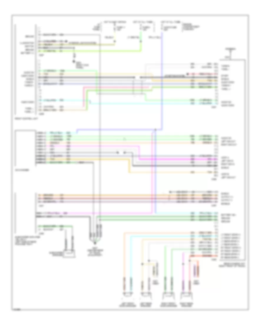
POWER DISTRIBUTION
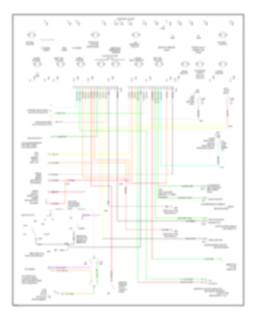
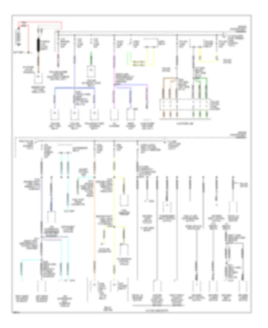
Power Distribution Wiring Diagram (1 of 4) for Ford Crown Victoria S 1997
List of elements for Power Distribution Wiring Diagram (1 of 4) for Ford Crown Victoria S 1997:
- (engine compt harn, near breakout to fuse box) s100
- (i/p harn, behind left side of i/p) s283
- (i/p harn, in breakout to blend door actuator) s245
- (rear harn, near breakout to right rear speaker)
- (rear harn, near breakout to right rear speaker) s407
- (seat harn, near recliner sensor) s310
- Air suspension compressor motor/ vent solenoid
- Air suspension/ evo steering module
- Air suspn pump/ speedo fuse 30a
- Audio fuse 25a
- Base vehicle and police
- Battery
- C216
- C251
- C319
- C452
- C520
- Cd changer
- Compressor relay
- Customer use
- Datalink connector
- Door locks/ seat motors circuit breaker 20a
- Driver's door module
- Driver's lumbar switch
- Driver's seat control switch
- Driver's seat module
- Eec fuse 30a
- Engine compartment fuse box
- Except natural gas
- From police a fuse (diagram 1 of 4)
- Fuel filler door release switch
- Fuel indicator module
- Fuel pump fuse 20a
- Fuel pump prime connector
- Fuel pump relay or fuel valve relay
- Fusible link (12 ga) (gray)
- Generator/ voltage regulator
- Horn fuse 15a
- Horn relay
- Instrument cluster (analog)
- Left rear air spring solenoid
- Master window/ door lock control switch
- Nca
- Passenger's seat control switch
- Pcm power relay
- Police fuse 30a
- Police fuse 50a
- Police option
- Police option fuse holder
- Police power relay
- Powertrain control module
- Rear chassis unit
- Red
- Relay center
- Right front window/ door lock control switch
- Right rear air spring solenoid
- S124 (engine harn, near breakout to fuel pump prime)
- S144 (engine compt harn, near breakout to fuse box)
- S151 (engine compt harn, near breakout to right headlamp)
- S282 (i/p harn, behind left side of i/p)
- S311 (seat harn, near driver's seat module)
- S406 (rear harn, near breakout to rear air spring solenoid)
- S411
- S425 (trunk harn, near breakout to trailer relays)
- Starter/ motor solenoid
- Subwoofer amplifier (jbl only)
- Tlr brakes fuse 30a
- Tlr tow fuse 20a
- Tlr tow fuse 40a
- To abs cont fuse (diagram 2 of 4)
- To air suspn pump/ speedo fuse (diagram 1 of 4)
- Trailer battery charging relay
- Trailer exterior lamps relay
- Trailer left turn relay
- Trailer right turn relay
- Trailer/camper adapter (electronic brake control unit)
- Trunk lid release switch
- W/ keyless entry
- W/ memory seats
- W/o keyless entry
- W/o memory seats
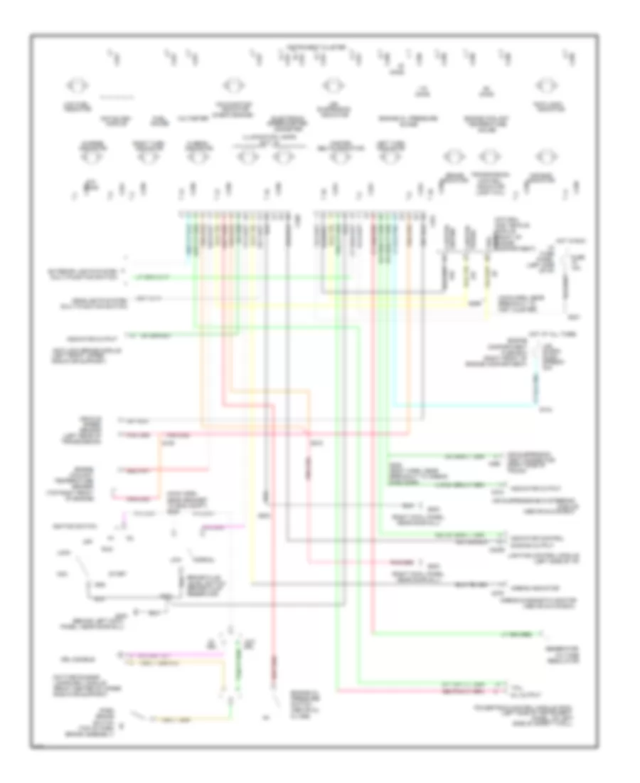
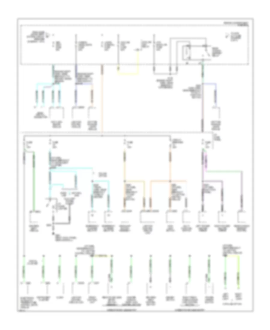
Power Distribution Wiring Diagram (2 of 4) for Ford Crown Victoria S 1997
List of elements for Power Distribution Wiring Diagram (2 of 4) for Ford Crown Victoria S 1997:
- (engine compt harn, near breakout to ground g101) s149
- (engine compt harn, near breakout to primary crash sensor) s146
- (i/p harn, near breakout to instrument cluster) s294
- (i/p harn, near breakout to lighting control module) s228
- Abs cont fuse 30a
- Anti-lock brake module
- Auxiliary power outlet
- C2028
- C2029
- C228
- C249
- C255
- C257
- C262
- C303
- Circuit breaker 20a
- Clock
- Cooling fan fuse 50a
- Cooling fan relay
- Daytime running lamps module
- Digital cluster
- Driver's seat control switch
- Driver's seat module
- Electronic automatic temperature control (eatc) module
- Emergency flasher relay #1
- Emergency flasher relay #2
- Engine compartment fuse box
- Evac and fill connector
- From door locks/ seat motors circuit breaker (diagram 1 of 4)
- Front control unit
- Fuse 10a
- Fuse 15a
- Fuse 20a
- G203 (right cowl panel, near door sill)
- Gaso- line
- Headlamp switch assembly
- Hi-beam headlights fuse 20a
- Htd backlite fuse 40a
- I/p cigar lighter
- I/p fuse panel
- Instrument cluster
- Lamps fuse pnl fuse 40a
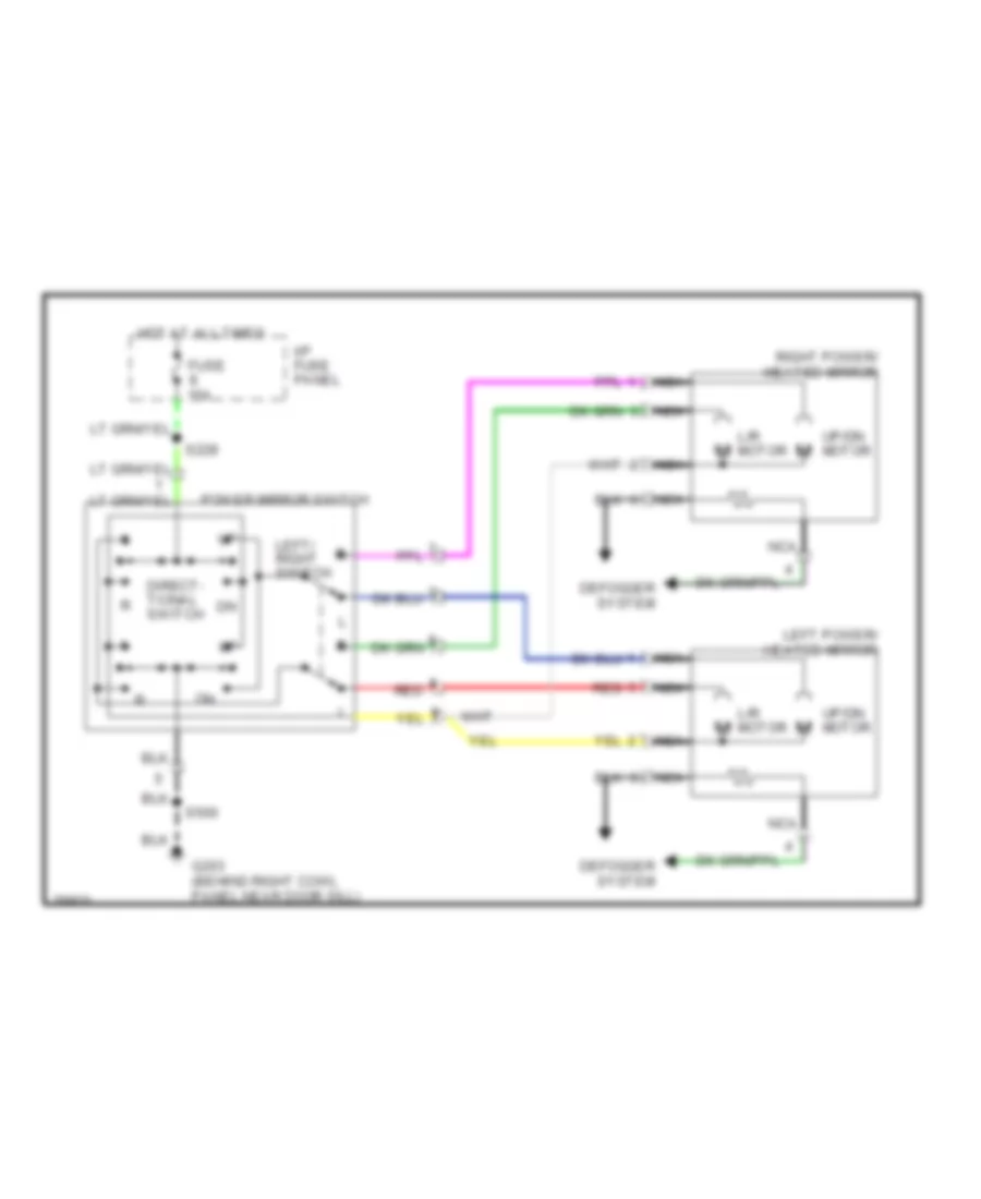
- Left power/ heated mirror
- Left spot light
- Lighting control module
- Lighting control module (lcm)
- Main light switch
- Master window/ door lock control switch
- Memory switch
- Multi- function switch
- Natural gas
- Nca
- Police option
- Power mirror switch
- Rear window defrost control
- Rear window defrost relay
- Remote keyless entry switch assembly
- Right front window/door lock control switch
- Right power/ heated mirror
- Right spot light
- S119 (engine compt harn, near breakout to fuse box)
- S206
- S252 (main harn, near breakout to multi- function switch)
- S253 (i/p harn, right kick panel)
- S262 (i/p harn, near breakout to lighting control module)
- S285 (i/p harn, near breakout to main light switch)
- S426 (trunk harn, near breakout to relay center)
- To str alt fuse (diagram 3 of 4)
- W/police option
- W/remote keyless entry
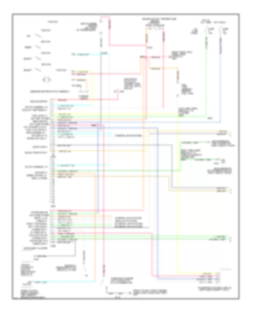
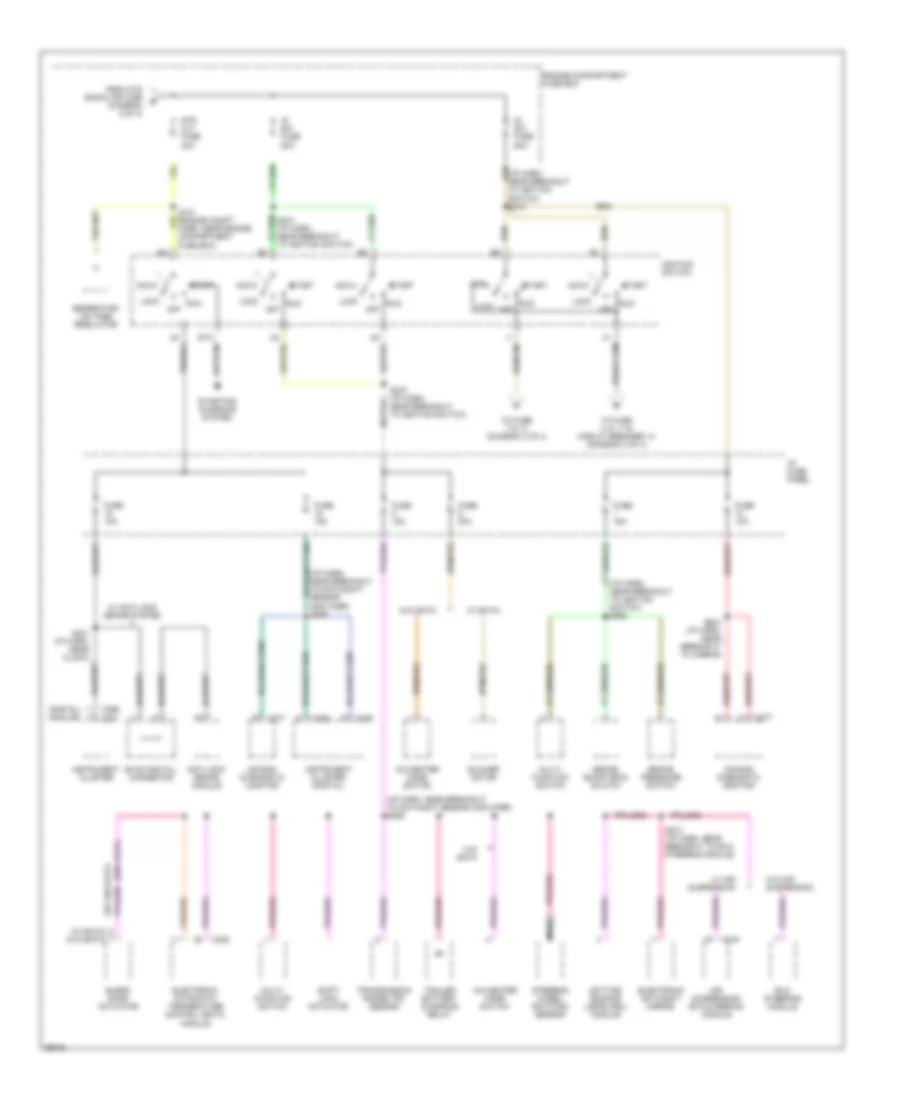
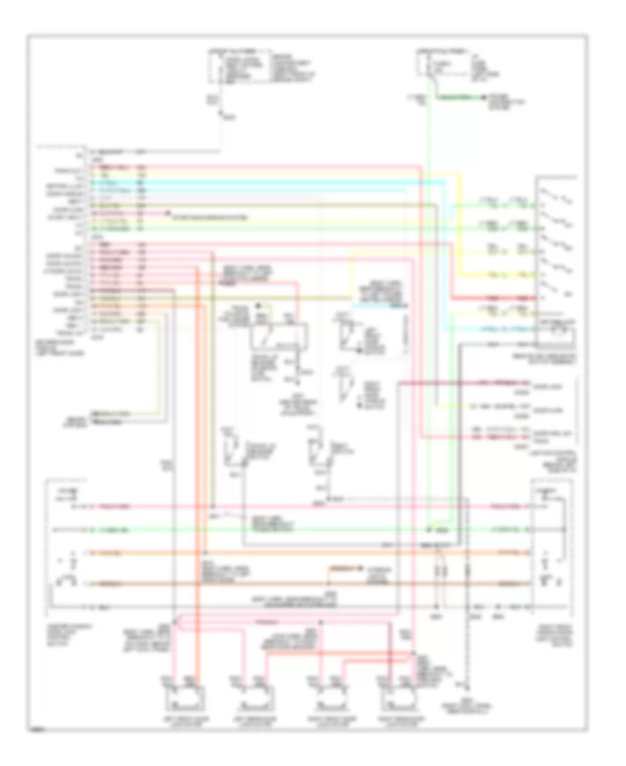
Power Distribution Wiring Diagram (3 of 4) for Ford Crown Victoria S 1997
List of elements for Power Distribution Wiring Diagram (3 of 4) for Ford Crown Victoria S 1997:
- (digital) (analog)
- (i/p harn, near breakout to day/night sensor amplifier) s226
- (i/p harn, near breakout to day/night/ sensor amplifier) s269
- (i/p harn, near breakout to ignition switch) s263
- (w/ eatc)
- (w/ eatc) (w/o eatc)
- (w/o eatc)
- A/c-heater mode switch
- Acc
- Air bag diagnostic monitor
- Air suspension/ evo steering module
- Anti-lock brake module
- Blend door actuator
- Blower motor
- Brake on/off (boo) switch
- Brake pressure switch
- C216
- C228
- C255
- C256
- C256 c251
- C277
- Daytime running lamps (drl) module
- Electronic automatic temperature control (eatc) module
- Electronic day/night mirror
- Engine compartment fuse box
- Evac and fill connector
- Evo steering module
- From htd backlite fuse (diagram 2 of 4)
- Fuse 10a
- Fuse 15a
- Fuse 30a
- Generator/ voltage regulator
- I/p fuse panel
- Ig sw fuse 50a
- Ignition switch
- Instrument cluster
- Instrument cluster (digital)
- Lock
- Multi- function switch
- Nca
- Near breakout to ignition switch)
- Off
- Run
- S231 (i/p harn, near clock)
- S254 (i/p harn, near breakout to airbag)
- S272 (i/p harn, near breakout to ignition switch)
- S274 (i/p harn, near breakout to evo steering module)
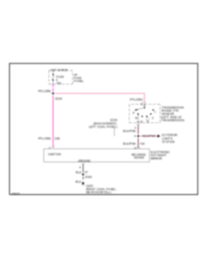
- Shift lock actuator
- Start
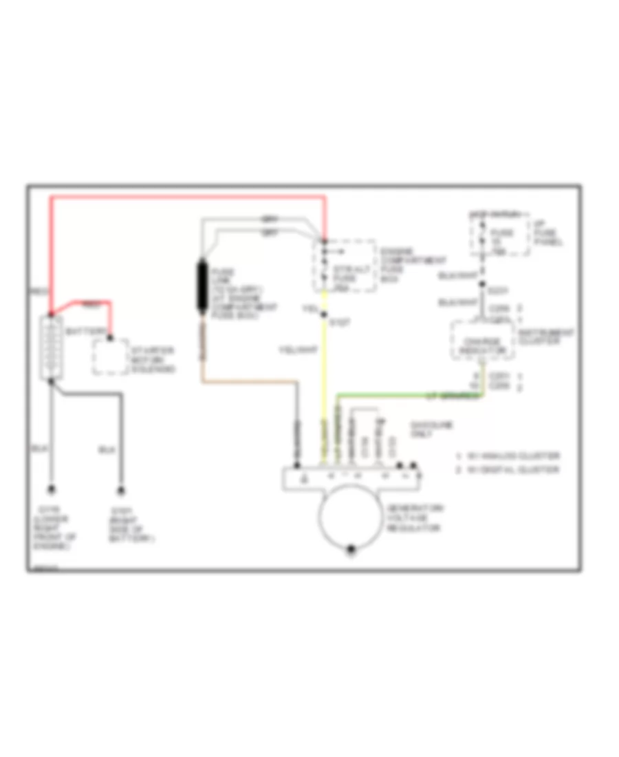
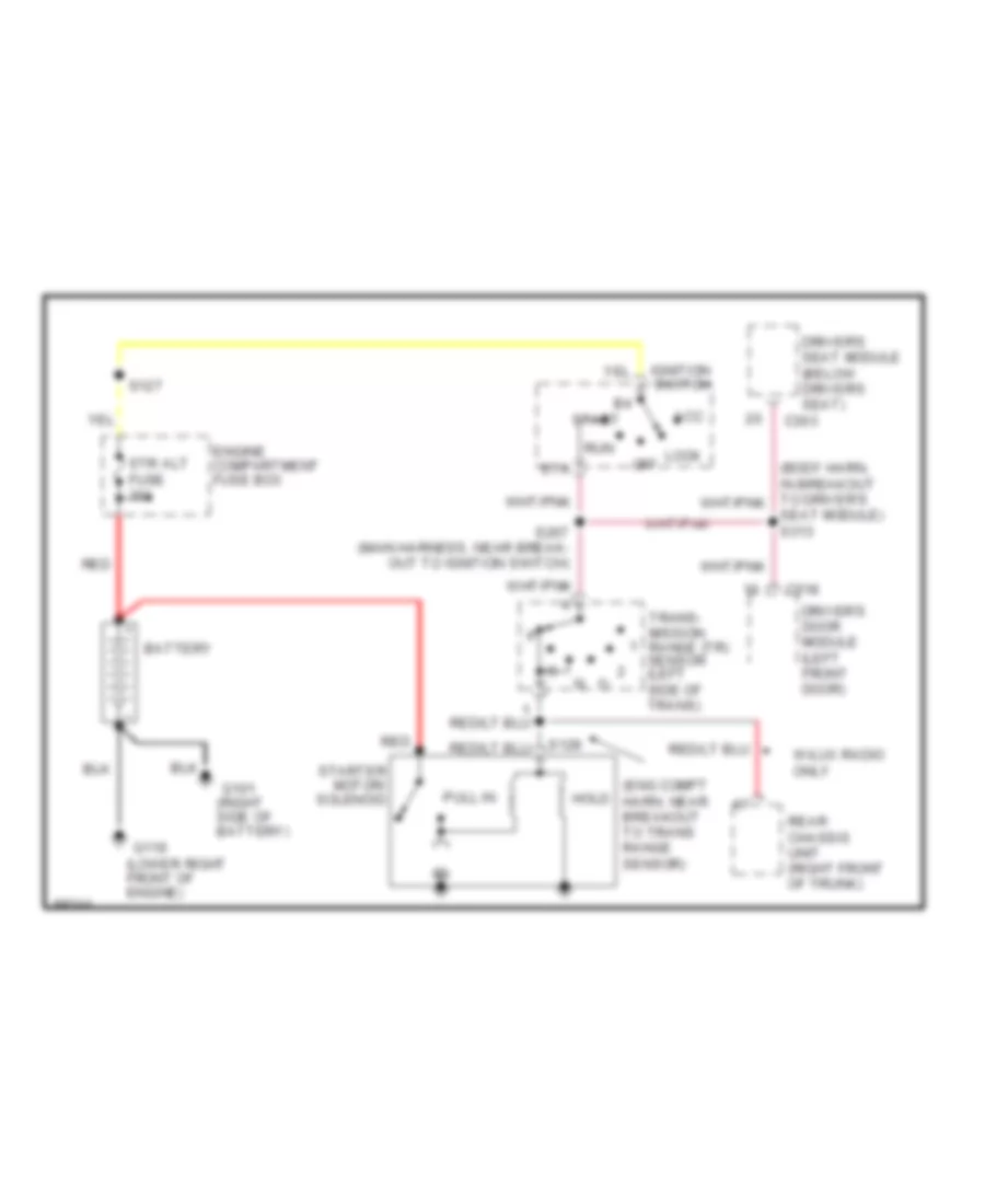
- Starting/ charging system
- Steering wheel rotation sensor
- Str alt fuse 30a
- To fuse 2, 6, 11 & circuit breaker 14 (diagram 4 of 4)
- To fuse 7 & 13 (diagram 4 of 4)
- Trailer battery charging relay
- Transmission range (tr) sensor
- W/ air suspension
- W/ anti-lock brake system
- W/ eatc
- W/o air suspension
- W/o eatc
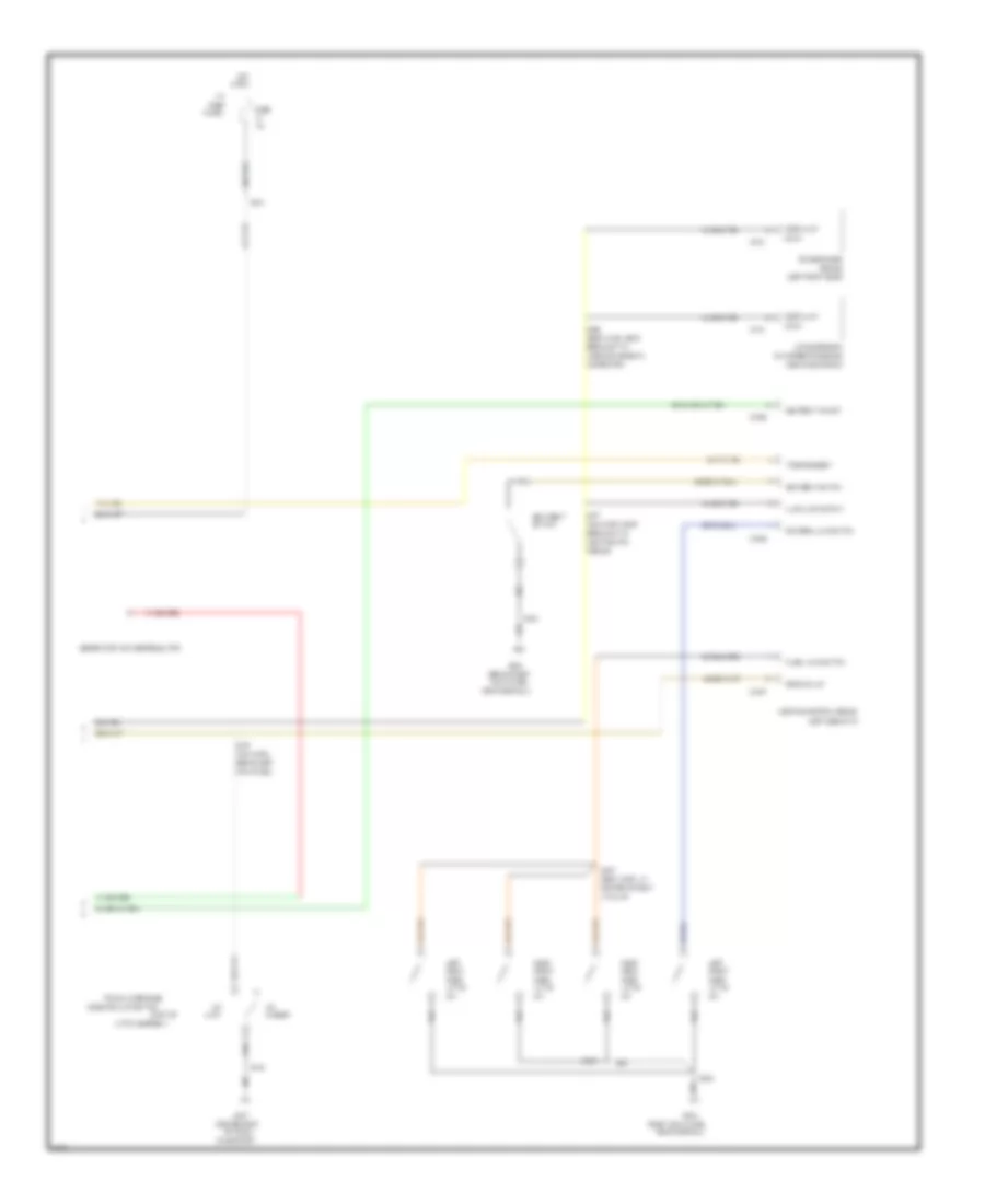
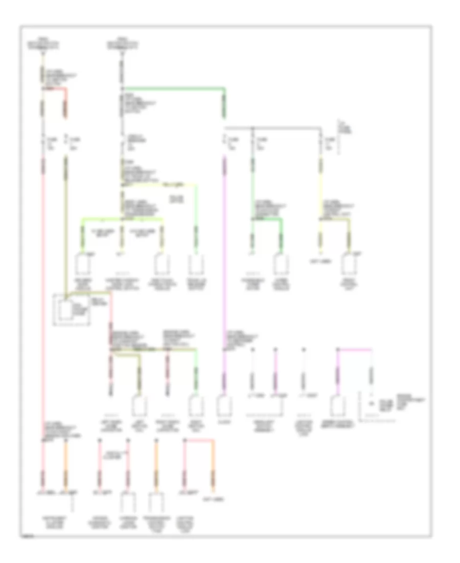
Power Distribution Wiring Diagram (4 of 4) for Ford Crown Victoria S 1997
List of elements for Power Distribution Wiring Diagram (4 of 4) for Ford Crown Victoria S 1997:
- (body harn, near breakout to transmission range sensor) s128
- (engine harn, near breakout to right ignition coil) s102
- (i/p harn, near breakout to datalink connector) s266
- (i/p harn, near breakout to day/night sensor amplifier) s276
- (i/p harn, near breakout to defogger control) s278
- (i/p harn, near breakout to front control unit) s224
- (i/p harn, near breakout to ignition switch) s221
- (i/p harn, near breakout to trunk lid release switch) s211
- (not used)
- Air bag diagnostic monitor
- C2027
- C249
- C250
- C251
- C257
- C262
- C276
- C520
- Circuit breaker 20a
- Clock
- Digital cluster
- Driver's door module
- Engine compartment fuse box
- From ignition switch (diagram 3 of 4)
- Front control unit
- Fuse 15a
- Fuse 25a
- Fuse 30a
- Headlight switch assembly
- I/p fuse panel
- Instrument cluster (analog)
- Left ignition coil
- Left radio noise capacitor
- Lighting control module (lcm)
- Master window/ door lock control switch
- Nca
- One touch window down module
- Pcm power diode
- Police option
- Police power relay
- Relay center
- Right ignition coil
- Right radio noise capacitor
- S103
- S225 (i/p harn, near breakout to ignition switch)
- Speed control servo assembly
- Transmission control switch (tcs)
- Trunk lid release switch
- W/ keyless entry
- W/o keyless entry
- Warning lamps monitor
- Windshield wiper motor
- Wiper control module
POWER DOOR LOCKS
Door Lock Wiring Diagram for Ford Crown Victoria S 1997
List of elements for Door Lock Wiring Diagram for Ford Crown Victoria S 1997:
- (body harn, near breakout to 16 pin conn, behin left cowl panel) s260
- (body harn, near breakout to boo switch) s261
- (main harn, near breakout to right rear door grommet) s291
- C2029
- Door lock in
- Door locks/ seat motors circuit breaker 20a
- Engine compartment fuse box (right front of engine compt)
- G203 (right cowl panel, near door sill)
- Hot at all times
- Interior lights system
- Left front door lock motor
- Left rear door lock motor
- Lighting control module (behind left side of i/p)
- Lock
- Master window/door lock control switch
- Right front door lock motor
- Right front window/door lock control switch
- Right rear door lock motor
- S208
- S245
- S288 (body harn, near breakout to air suspsn/ evo strng mod)
- S503
- S600
- Unlock
Keyless Entry Wiring Diagram for Ford Crown Victoria S 1997
List of elements for Keyless Entry Wiring Diagram for Ford Crown Victoria S 1997:
- (body harn, near breakout to boo switch)
- (body harn, near breakout to left power heated mirror) s506
- (body harn, near breakout to left pwr htd mirror) s506
- 1/2
- 3/4
- 5/6
- 7/8
- 9/0
- C2026
- C2027
- C2029
- C518
- C519
- C520
- Door ajar
- Door handle
- Door hndl sw
- Door lock
- Door locks/ seat motors circuit breaker 20a
- Door unlock
- Driver's door module (left front door)
- Engine compartment fuse box (right front of engine compt)
- Fuse 8 15a
- G203 (right cowl panel, near door sill)
- G407 (center rear of trunk, on support)
- Hot at all times
- I/p fuse panel (left side of i/p)
- Interior lights system
- Keypad illum
- Keypad lamp
- Left front door handle switch
- Left front door lock motor
- Left rear door lock motor
- Lf door unlck
- Lighting control module (behind left side of i/p)
- Lock
- Master window/ door lock control switch
- Mem 1
- Mem 2
- Memory systems
- Nca
- Panic
- Panic out
- Power distribution system
- Red
- Remote keyless entry switch assembly
- Right front door handle switch
- Right front door lock motor
- Right front window/door lock control switch
- Right rear door lock motor
- S208
- S228
- S245
- S260 (body harn, near breakout to 16 pin conn, behind left cowl panel)
- S261 (body harn, near breakout to park boo switch)
- S288 (body harn, near breakout to air suspsn/ evo strg mod)
- S291 (main harn, near breakout to right rear door grommet)
- S304
- S403
- S500
- S503
- S510 (body harn, near breakout to left front door)
- S511
- S600
- Seat
- Seat switch
- Start input
- Starting/charging system
- Trunk
- Trunk lid
- Trunk lid release solenoid/ ajar switch
- Trunk lid release switch
- Trunk, tailgate, fuel doors system
- Unlock
POWER MIRRORS
Photochromic Mirror Wiring Diagram for Ford Crown Victoria S 1997
List of elements for Photochromic Mirror Wiring Diagram for Ford Crown Victoria S 1997:
- Electronic day/night mirror
- Exterior lights system
- Fuse 15a
- G203 (right cowl panel, near door sill)
- Ground
- Hot in run
- I/p fuse panel
- Ignition
- Reverse
- S226
- S230 (main harness, left cowl panel)
- S500
- Transmission range (tr) sensor (left side of transmission)
Power Mirror Wiring Diagram for Ford Crown Victoria S 1997
List of elements for Power Mirror Wiring Diagram for Ford Crown Victoria S 1997:
- Defogger system
- Direct- tional switch
- Fuse 15a
- G203 (behind right cowl panel near door sill)
- Hot at all times
- I/p fuse panel
- L/r motor
- Left power/ heated mirror
- Left/ right switch
- Nca
- Power mirror switch
- Red
- Right power/ heated mirror
- S228
- S500
- Up/dn motor
POWER SEATS
6-Way, Recliner & Lumbar Power Seat Wiring Diagram for Ford Crown Victoria S 1997
List of elements for 6-Way, Recliner & Lumbar Power Seat Wiring Diagram for Ford Crown Victoria S 1997:
- nca
- Door lock/seat motors circuit breaker 20a
- Driver's lumbar air bladder
- Driver's lumbar switch
- Driver's power lumbar compressor (under front of left seat assembly)
- Driver's power seat motor
- Driver's recliner motor
- Driver's seat control switch
- Engine compartment fuse box (right front of engine compt)
- Entire seat
- Front height motor
- Front of seat
- Fwd
- Fwd/ rwd motor
- G203 (right cowl panel, near door sill)
- Hot at all times
- Inflate
- Nca
- Passenger's power seat motor
- Passenger's recliner motor
- Passenger's seat control switch
- Rear height motor
- Rear of seat
- Red
- Red
- Rwd
- S208
- S245
- S304
- S500
- S600
- Seat back
- Vent
Driver Power Seat Wiring Diagram for Ford Crown Victoria S 1997
List of elements for Driver Power Seat Wiring Diagram for Ford Crown Victoria S 1997:
- Door locks/ seat motors circuit breaker 20a
- Driver's power seat motor
- Driver's seat control switch
- Engine compartment fuse box (right front of engine compartment)
- Entire seat
- Front height motor
- Front of seat
- Fwd
- Fwd/ rwd motor
- G203 (right cowl panel, near door sill)
- Hot at all times
- Nca
- Rear height motor
- Rear of seat
- Red
- Rwd
- S245
- S304
POWER WINDOWS
Power Window Wiring Diagram for Ford Crown Victoria S 1997
List of elements for Power Window Wiring Diagram for Ford Crown Victoria S 1997:
- (2 led's per switch)
- (body harn, near break- out to brake on/ off switch) s264
- (body harn, near breakout to air suspension/evo steering module) s288
- (left front door)
- C298
- C518
- C520
- Circuit breaker 20a
- Door lock control switch
- Driver's door module (w/ keyless entry)
- Entry
- G203 (right cowl panel, near door sill)
- Hot in acc or run
- I/p fuse panel (left side of i/p)
- Ign
- Interior lights system
- Keyless
- Left
- Left front
- Left front window motor
- Left front window motor (police only)
- Left rear
- Left rear window motor
- Master window/ door lock control switch
- Nca
- One touch window down module (w/o keyless entry)
- Others
- Police
- Rear window control switch
- Right
- Right front
- Right front window motor
- Right rear
- Right rear window motor
- S208
- S218
- S500
- S503
- S504 (body harn, near breakout to left front door speaker)
- S600
- Solid state
- W/ keyless entry
- W/o
- W/o keyless entry
- Window lock switch
- Wndw dn
- Wndw up
RADIO
Base Radio for Ford Crown Victoria S 1997
List of elements for Base Radio for Ford Crown Victoria S 1997:
- Battery (b+)
- C257
- C258
- Front control unit
- Fuse 11 15a
- Fuse 8 15a
- G203 (right kick panel)
- Ground
- Hot at all times
- Hot in accy or run
- I/p fuse panel
- Ignition
- Illumination
- Interior lights system
- Left front door speaker
- Left frt
- Left rear speaker
- Left rr
- Right front door speaker
- Right frt
- Right rear speaker
- Right rr
Premium Sound Radio Wiring Diagram for Ford Crown Victoria S 1997
List of elements for Premium Sound Radio Wiring Diagram for Ford Crown Victoria S 1997:
- (acp) a
- (acp) b
- (jbl only)
- (not used)
- Antenna
- Audio comm
- Audio fuse 25a
- Audio on
- Battery (+)
- Battery (b+)
- C257
- C259
- C401
- C451
- C452
- C490
- C497
- C498
- Cd changer
- Enable
- Engine compartment fuse box
- Front control unit
- Fuse 11 15a
- Fuse 8 15a
- G203 (right kick panel)
- G407 (center rear of trunk, on support)
- Ground
- Hot at all times
- Hot in accy or run
- I/p fuse panel
- Ignition
- Illumination
- Interior lights system
- Left front door speaker
- Left rear speaker
- Left sig in
- Left sig out
- Lt front spkr (+)
- Lt front spkr (-)
- Lt rear spkr (+)
- Lt rear spkr (-)
- Nca
- Output (+)
- Output (-)
- Rear chassis unit (right front of trunk)
- Right front door speaker
- Right rear speaker
- Right sig in
- Right sig out
- Rt front spkr (+)
- Rt front spkr (-)
- Rt rear spkr (+)
- Rt rear spkr (-)
- Shield
- Start
- Starting system
- Subwoofer amplifier (jbl only) (left side of rear package tray)
- Subwoofer speaker
- Tan
- Tape l +
- Tape l -
- Tape r +
- Tape r -
SHIFT INTERLOCKS
Shift Interlock Wiring Diagram for Ford Crown Victoria S 1997
List of elements for Shift Interlock Wiring Diagram for Ford Crown Victoria S 1997:
- (main harn, in breakout to multi-function switch) s243
- Brake pedal position (bpp) switch (top of brake pedal support)
- Exterior lights system
- Fuse 1 15a
- Fuse 5 15a
- G200 (behind left kick panel)
- Hot at all times
- Hot in run
- I/p fuse panel (below dash, left of steering column)
- S203
- S226
- S258 (body harn, in breakout to brake pedal position (bpp) switch)
- S263
- Shift lock actuator (at bottom of steering column)
- Solid state
STARTING/CHARGING
Charging Wiring Diagram for Ford Crown Victoria S 1997
List of elements for Charging Wiring Diagram for Ford Crown Victoria S 1997:
- Battery
- C153
- C154
- C251
- C251 c256
- C256
- Charge indicator
- Engine compartment fuse box
- Fuse 10a
- G101 (right side of battery)
- G119 (lower right front of engine)
- Gasoline only
- Generator/ voltage regulator
- Hot in run
- I/p fuse panel
- Instrument cluster
- Red
- S127
- S231
- Starter motor/ solenoid
- Str alt fuse 30a
- W/ analog cluster
- W/ digital cluster
Starting Wiring Diagram for Ford Crown Victoria S 1997
List of elements for Starting Wiring Diagram for Ford Crown Victoria S 1997:
- (eng compt harn, near breakout to trans range sensor)
- (lower right front of engine)
- Acc
- Battery
- C303
- C518
- Driver's door module (left front door)
- Driver's seat module (below driver's seat)
- Engine compartment fuse box
- G101 (right side of battery)
- G119
- Hold
- Ignition switch
- Lock
- Off
- Pull in
- Rear chassis unit (right front of trunk)
- Red
- Run
- S127
- S128
- S267 (main harness, near break- out to ignition switch)
- Seat module) s313
- Sta
- Start
- Starter motor/ solenoid
- Str alt fuse 30a
- Trans- mission range (tr) sensor (left side of trans)
- W/lux radio only
SUPPLEMENTAL RESTRAINTS
Supplemental Restraint Wiring Diagram for Ford Crown Victoria S 1997
List of elements for Supplemental Restraint Wiring Diagram for Ford Crown Victoria S 1997:
- (behind right side of i/p) air bag diagnostic connector
- (i/p harn, near air bag diagnostic monitor breakout) s254
- (i/p harn, near blend door actuator breakout)
- (i/p harn, near day/ night sensor amp breakout)
- (i/p harn, near glove- box lamp breakout)
- Air bag diagnostic monitor (above glove box)
- Air bag ind
- Air bag indicator control
- C276
- C277
- Clock- spring assembly
- Computer data lines
- Data link
- Diag conn
- Driver's air bag
- Drvr air bag
- Fuse 10 10a
- Fuse 13 15a
- Fuse 18 15a
- G203 (right cowl panel)
- Gnd
- Hot at all times
- Hot in run
- Hot in run or start
- I/p fuse panel (below left side of i/p)
- Instrument cluster
- L crash sens
- Left primary crash sensor (left front upper radiator support)
- Nca
- Pass air bag
- Passenger's air bag
- Pwr (bat)
- Pwr (run)
- R crash sens
- Right primary crash sensor (right front upper radiator support)
- S206
- S208
- S269
- S276
- Shorting bar
- Tan/ red
- Tan/red
TRANSMISSION
Transmission Wiring Diagram for Ford Crown Victoria S 1997
List of elements for Transmission Wiring Diagram for Ford Crown Victoria S 1997:
- (harness 7c078, left rear of engine compartment)
- (harness 7c078, left rear of engine compt) s125
- (harness 9d930, lower right rear of engine compt)
- (harness 9d930, near injector 8) s126
- (in harn 12a581, left rear of engine compt)
- (left side of transmission) transmission range (tr) sensor
- (ngv) (gas)
- 4r70w transmission
- A/c cycling
- Airbag diagnostic monitor, lighting control module, instrument cluster
- Analog
- Boo switch input
- Brake on/off (boo) switch (near top of brake pedal)
- Brake press switch, multi- function switch
- C250
- C255
- Data link +
- Data link -
- Data link connector
- Data link power
- Digital
- Eec fuse 30a
- Elect press cntrl
- Electronic pressure control (epc) solenoid
- Engine compartment fuse box (right front of engine compartment)
- Engine controls system
- Engine coolant temperature (ect) sensor (on top left front of engine)
- Fuse 25a
- G101 (side of battery)
- G203 (behind
- Ground
- Hot at all times
- Hot in run or start
- I/p fuse panel (below dash, left of steering column)
- I/p fuse panel (below dash, left of steering column)
- Ignition coils, radio noise capacitors
- Ignition power
- Instrument cluster
- Instrument cluster, cruise control
- Intake air temp
- Intake air temperature (iat) sensor (on rear of air cleaner assembly)
- Kapwr
- Maf return
- Maf sensor sig
- Mass air flow (maf) sensor (behind air cleaner assembly)
- Output shaft sig
- Output shaft speed (oss) sensor (left rear of trans- mission)
- Pcm data link connector (partial) (behind left side of dash)
- Pcm power diode
- Pcm power relay
- Powertrain control module (pcm) (behind left side of dash)
- Red
- Red red
- Ref votage
- Relay center (left side of engine compartment)
- Right kick panel)
- S100
- S105
- S106
- S109
- S114
- S123
- S129 (in harness 21a581, left rear of engine compt)
- S147
- S148
- S243 s295
- S263
- S276
- S296 s118
- S297 s117
- Shift sol 1
- Shift solenoid 2
- Shift solenoids
- Signal control
- Ss1
- Ss2
- Tci lamp
- Temp sens
- Throttle position (tp) sensor (on throttle body)
- To a/c system
- Torque conv sol
- Torque converter clutch (tcc) solenoid
- Tps signal
- Tr sens/pnp sw
- Trans cntrl sw
- Trans control indicator lamp
- Trans temp
- Transmission control switch (tcs) (bottom of steering column)
- Transmission fluid temperature sensor
- Vehicle speed sensor (left rear of trans- mission)
- Vss (-)
- Vss signal
TRUNK, TAILGATE, FUEL DOOR
Fuel Door Release Wiring Diagram for Ford Crown Victoria S 1997
List of elements for Fuel Door Release Wiring Diagram for Ford Crown Victoria S 1997:
- Door locks/ seat motors circuit breaker 20a
- Engine compartment fuse box (right front of engine compt, behind battery)
- Fuel filler door release solenoid (left side of trunk, near fuel door)
- Fuel filler door release switch
- G407 (center rear of trunk, on support)
- Hot at all times
- S245
- S402
Trunk Release Wiring Diagram, with Keyless Entry for Ford Crown Victoria S 1997
List of elements for Trunk Release Wiring Diagram, with Keyless Entry for Ford Crown Victoria S 1997:
- "trunk ajar" input
- C254
- C519
- C520
- Decklid ajar switch
- Digital cluster only
- Door locks/ seat motors circuit breaker 20a
- Driver's door module (in center left front door)
- Engine compartment fuse box (right front of engine compt, behind battery)
- G203 (right cowl panel, near door sill)
- G407 (center rear of trunk, on support)
- Hot at all times
- Instrument cluster (digital)
- Lighting control module (lcm) (behind left side of i/p)
- Release out
- Release sw
- S245
- S403
- S500
- S506 (body harn, near breakout to left power heated mirror)
- Trunk lid release solenoid/ajar switch (center rear of trunk lid, part of latch assembly)
- Trunk lid release switch
Trunk Release Wiring Diagram, without Keyless Entry for Ford Crown Victoria S 1997
List of elements for Trunk Release Wiring Diagram, without Keyless Entry for Ford Crown Victoria S 1997:
- "trunk ajar" input
- (police only)
- C254
- C298
- Circuit breaker 20a
- Decklid ajar switch
- Digital cluster only
- Door locks/ seat motors circuit breaker 20a
- Engine compartment fuse box (right front of engine compt, behind battery)
- G407 (center rear of trunk, on support)
- Hot at all times
- Hot in acc or run
- I/p fuse panel (left side of i/p)
- Instru- ment cluster (digital)
- Lighting control module (lcm) (behind left side of i/p)
- Police only
- S205 (main harn, near breakout to 3 pin in-line conn, behind left side of i/p)
- S211
- S245
- S273 (main harn, near breakout to 16 pin in-line conn, behind left cowl panel)
- S403
- Trunk lid release solenoid/ajar switch (center rear of trunk lid, part of latch assembly)
- Trunk lid release switch
WARNING SYSTEMS
Warning System Wiring Diagrams for Ford Crown Victoria S 1997
List of elements for Warning System Wiring Diagrams for Ford Crown Victoria S 1997:
- (bady harn, near right "a" pillar)
- (left cowl panel, near door sill)
- (police)
- (right cowl panel, near door sill)
- *10 **11
- *analog **digital
- Ajar lamp output
- Autolamp delay
- Autolamp enable
- Autolamp ind
- Autolamp on/off
- B(+) vbat 4
- B+ to module
- C2026
- C2027
- C2028
- C2029
- C255
- C262
- Circuit breaker 20a
- Computer data lines system
- Courtesy lps out
- Decklid ajar
- Defogger system
- Demand lt out
- Dimming out
- Dimming output
- Dlc
- Dome lamp sw
- Door handle sw
- Door locks input
- Door locks system
- Driver's ajar sw
- Except police
- Exterior lights system
- Fasten belts input *c251 **c256
- Flasher output
- Flasher pwr in
- Fuse 15a
- G200
- G203
- G203 (right cowl panel, near door sill)
- Ground
- Hazard ind
- Head
- Headlamp sw
- Headlamp switch assembly
- Headlights system
- Heated backlt sw
- Hi beam sw input
- Hi beams out
- Horn relay output
- Horns system
- Hot at all times
- Hot in accy or run
- Hot in start or run
- I/p fuse panel (left side of i/p)
- Ignition
- Instrument cluster
- Instrument cluster system
- Interior lights system
- Key in
- Key warning switch
- Left front door latch switch
- Left rear door latch switch
- Lighting control module (lcm) (left side of i/p)
- Low beams out
- Nca
- Off
- Panel dim down
- Panel dim up
- Panic alarm
- Park
- Parklamp output
- Parklamp sw
- Pass. ajar sw
- Police
- Relay output
- Right front door latch switch
- Right rear door latch switch
- S200
- S204
- S207
- S208
- S227
- S259
- S262
- S275
- S276
- S285
- S304
- S500
- Seat belt switch
- Seatbelt ind
- Seatbelt sw
- Sound tone output (digital only)
- Tone req or grd
- Trunk, tailgate, fuel doors system
WIPER/WASHER
Wiper/Washer Wiring Diagram for Ford Crown Victoria S 1997
List of elements for Wiper/Washer Wiring Diagram for Ford Crown Victoria S 1997:
- (1996-97)
- (1998)
- (behind left kick panel) g200
- 100k ohms
- 3.3k ohms
- 4.08k
- 7.25k
- Fuse 30a
- G101 (front of right fender)
- Hot in acc or run
- I/p fuse panel (below dash, left of steering column)
- Int max
- Int min
- Multi- function switch
- Off
- Off 36.27k ohms
- Ohms
- Parked
- Parking
- Red
- Run
- S112
- S207
- S266
- Wash
- Windshield washer pump (in fluid reservoir)
- Windshield wiper motor (top center of firewall)
- Wiper control module (behind center of of dash, above warning lamp module)

 Čeština
 Dansk
Dansk Deutsch
 Ελληνικά
 English
 English
 Español
 Suomi
Suomi Français
 עברית
עברית Hrvatski
 Magyar
 Italiano
 日本語
日本語 한국어
한국어 Nederlands
 Polski
 Português
 Português
 Română
 Русский
 Slovenčina
 Slovenščina
 Svenska
 Türkçe
 中文 (中国)