AIR CONDITIONING
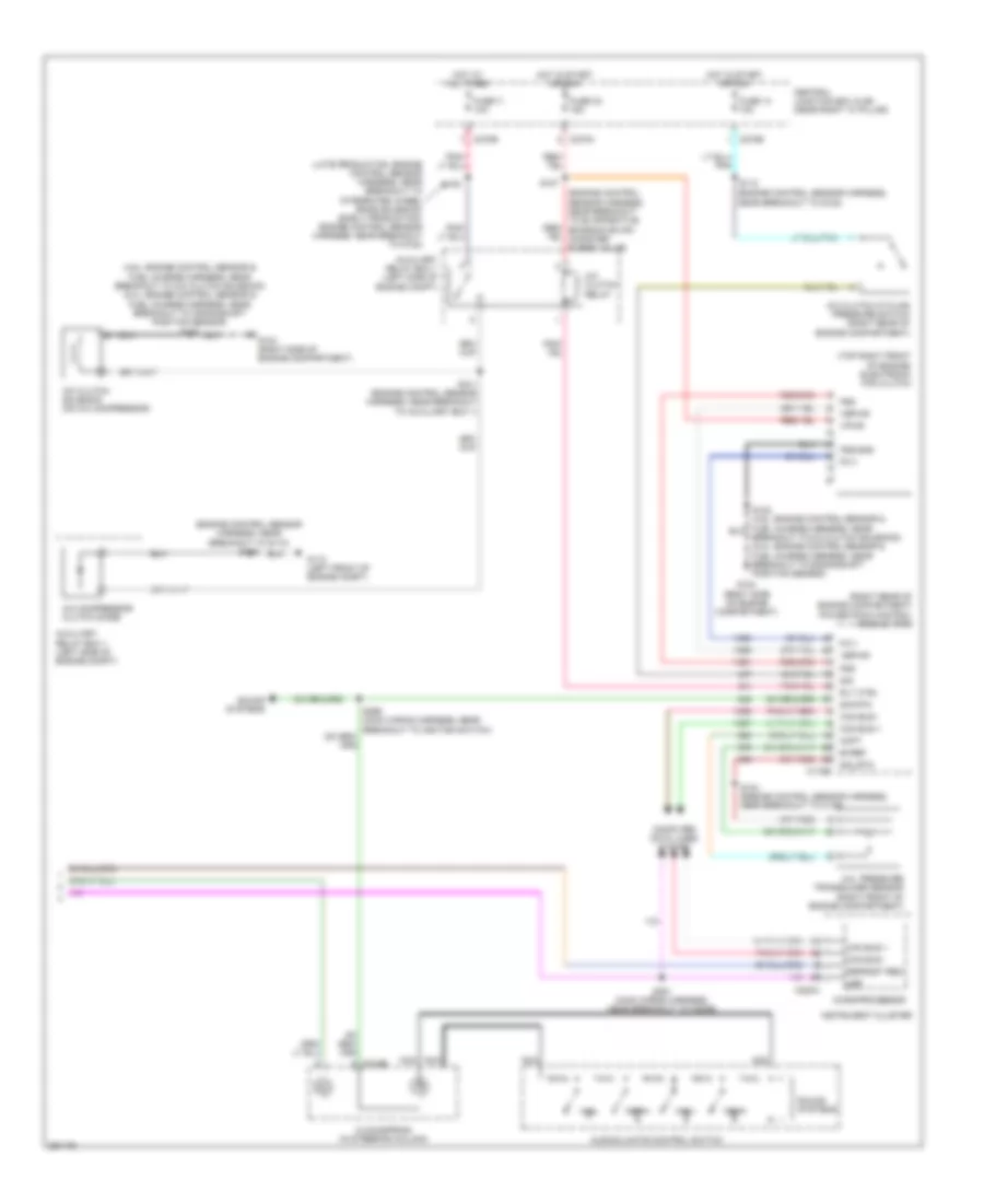
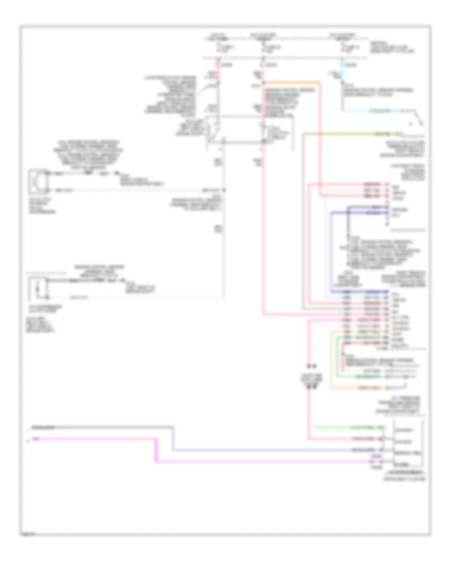
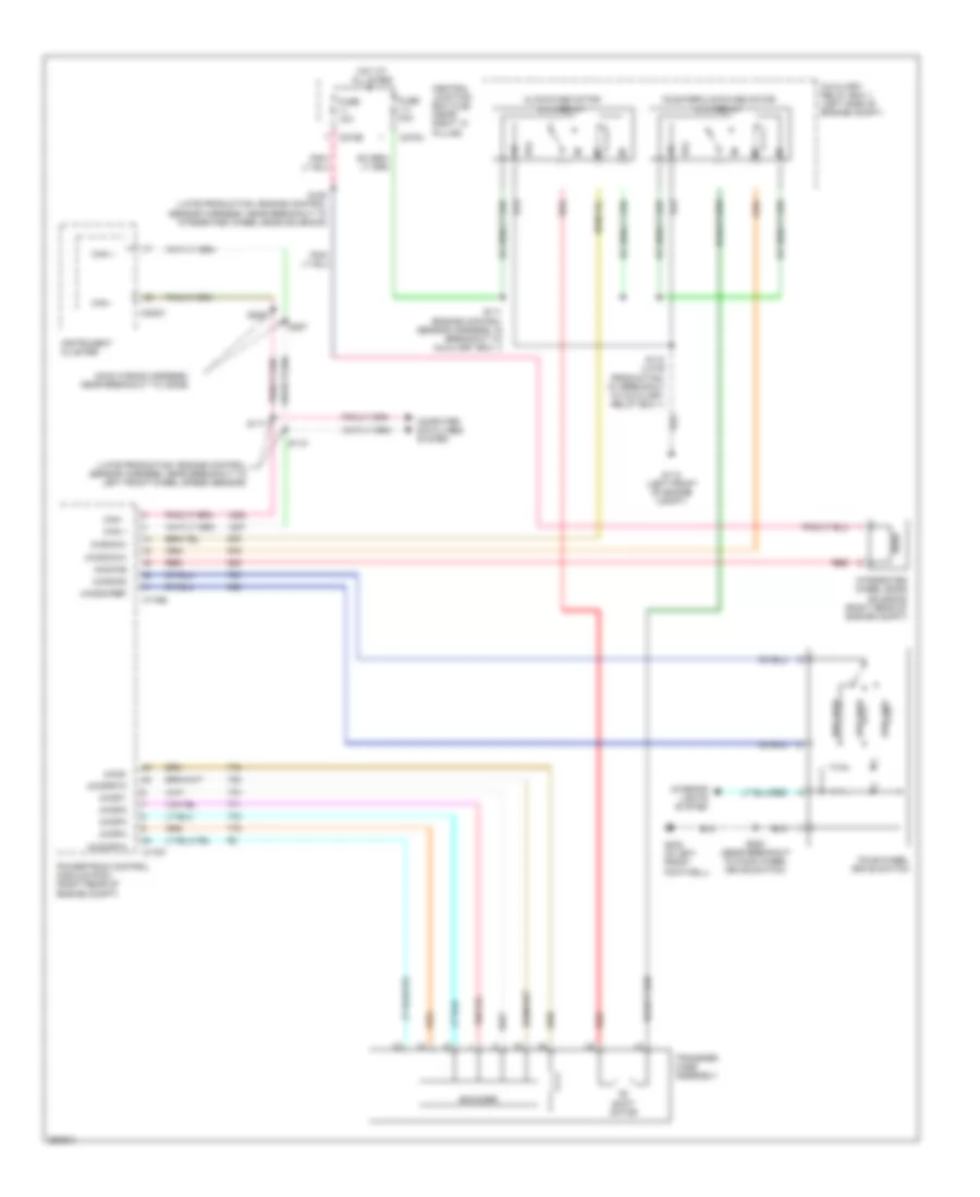
Automatic A/C Wiring Diagram (1 of 2) for Ford Pickup F150 2007
 https://portal-diagnostov.com/license.html
Automotive Electricians Portal FZCO
Automotive Electricians Portal FZCO
https://portal-diagnostov.com/license.html
https://portal-diagnostov.com/license.html
Automotive Electricians Portal FZCO
Automotive Electricians Portal FZCO
List of elements for Automatic A/C Wiring Diagram (1 of 2) for Ford Pickup F150 2007:
- (heater blower motor wiring harness, in breakout to c299)
- (in right front footwell) g203
- +/-
- Anti- theft system
- Autolamp/sunload sensor (top left side of dash)
- C228a
- C228b
- C270e
- C270g
- C3008b
- Central junction box (cjb) (near right "a" pillar)
- Defogger system
- Defrost req
- Electronic automatic temperature control (eatc) module (center of dash)
- Fresh/recirculation door actuator (behind right side of dash)
- Front blower motor (behind dash)
- Front blower motor relay
- Front blower motor speed controller (right "a" pillar)
- Fuse 116 30a
- Fuse 13 10a
- Fuse 5 7.5a
- G200 (left "a" pillar)
- Gnd
- High ind sig
- High/low on/off sig vref
- Hot at all times
- Hot in start or run
- In-vehicle temperature sensor (behind dash panel)
- Interior lights system
- Light sensor
- Low ind sig
- Low ind sig high/low on/off sig
- Mtr ctrl
- Panel mode actuator (behind center of dash)
- Pats ind
- Red
- Rly ctrl
- Rly sw pwr
- S202
- S204 (heater blower motor wiring harness, in breakout to c299)
- S208
- S208 (main wiring harness, near breakout to indicator flasher relay)
- S210 (main wiring harness, in breakout to electronic manual temperature control (emtc) module)
- S236 (main wiring harness)
- S286 (main wiring harness, near breakout to front blower motor speed controller)
- Seats system
- Sens
- Sig
- Sig rtn
- Sun sensor
- Temperature blend door actuator (behind center of dash)
- Ubp
- Vbatt
- Vehicle security module (left rear of cab)
- Vpwr
- Vref
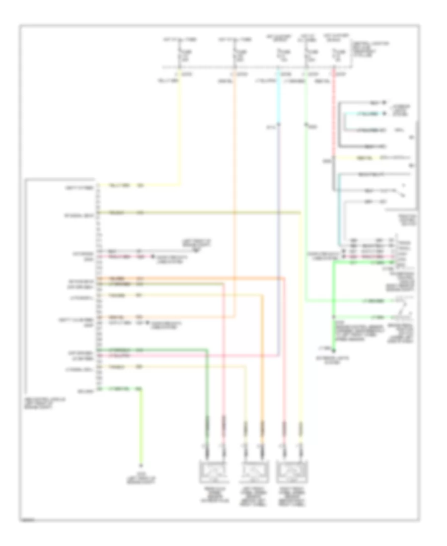
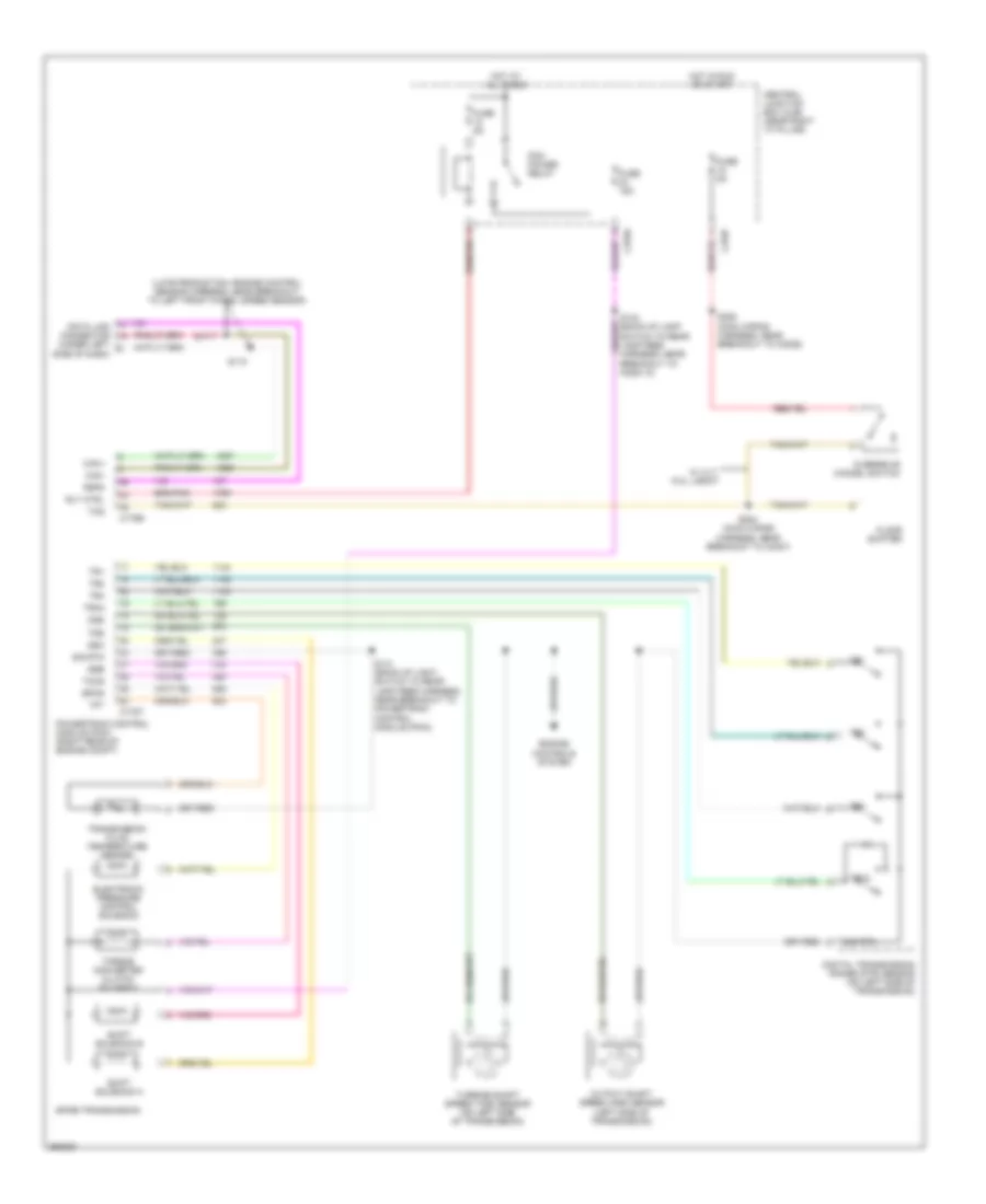
Automatic A/C Wiring Diagram (2 of 2) for Ford Pickup F150 2007
List of elements for Automatic A/C Wiring Diagram (2 of 2) for Ford Pickup F150 2007:
- (4.6l: engine control sensor & fuel charge harness, near breakout to a/c clutch solenoid) (5.4l: engine control sensor & fuel charge harness, near breakout to crankshaft position sensor) s122
- (engine control sensor harness, near breakout to g102)
- (engine control sensor harness, near breakout to g110) s116
- (late production: engine control sensor harness, near breakout to integrated wheel ends solenoid) (early production: engine control sensor harness, near breakout to g102)
- (right rear of engine compartment) powertrain control module (pcm)
- (top right front of engine) electronic fan clutch
- A/c pressure transducer sensor (right front of engine compartment)
- A/c clutch cycling pressure switch (right rear of engine compartment)
- A/c clutch relay
- A/c clutch solenoid (on a/c compressor)
- A/c compressor clutch diode
- Acpt
- Audio/climate control switch
- Auxiliary relay box 1 (left side of engine compt)
- Breakout to a/c clutch solenoid) (5.4l: engine control sensor & fuel charge harness, near breakout to crankshaft position sensor)
- Bvref
- C175b
- C218b
- C220a
- C270a
- C270b
- Can bus +
- Can bus -
- Central junction box (cjb) (near right "a" pillar)
- Clockspring (in steering column)
- Computer data lines system
- Defrost req
- Fan+
- Fan-
- Fc-v
- Fss
- Fss-gnd
- Fuse 11 10a
- Fuse 14 10a
- Fuse 32 15a
- G104 (right side of engine compartment)
- G110 (left front of engine compt)
- Hot at all times
- Hot in start or run
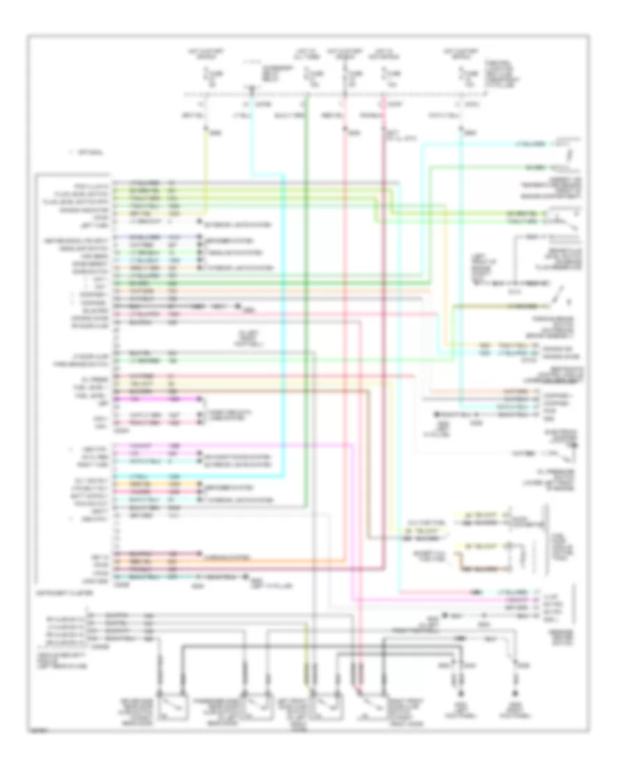
- Instrument cluster
- Microprocessor
- Nca
- Rly ctrl
- S101 (engine control sensor harness, near breakout to auxiliary box 1)
- S104 (engine control sensor harness, near breakout to c139)
- S105
- S107
- S112
- S281 (main wiring harness, near breakout to c2026)
- Sig
- Sig rtn
- Sig_rtn
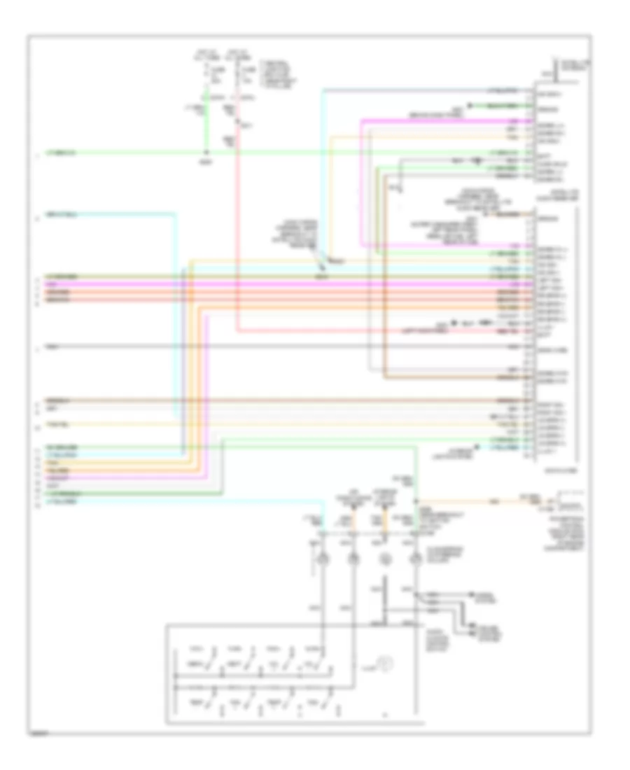
- Sound systems
- Temp+
- Temp-
- Ubp
- Vbpwr
- Vpwr
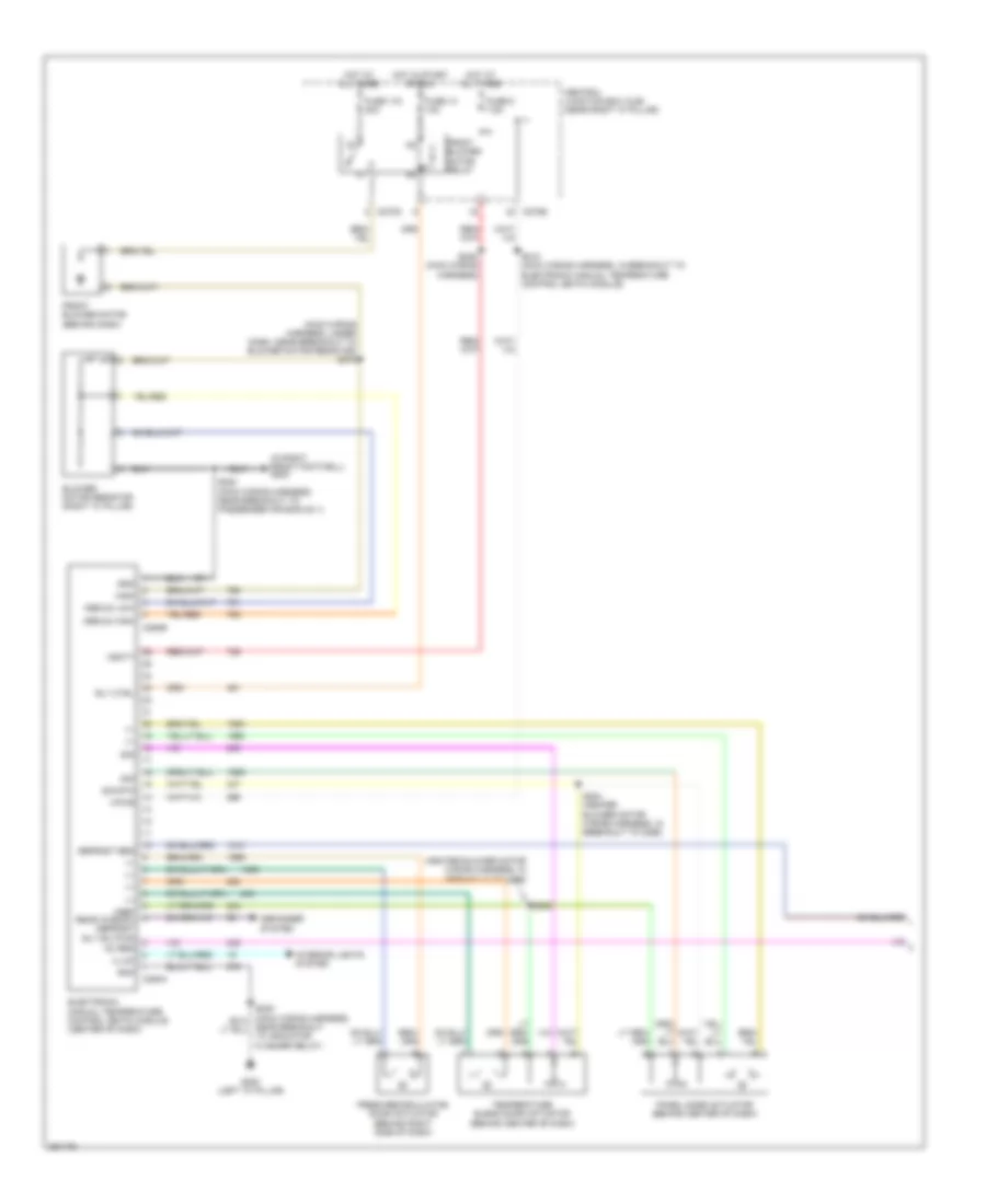
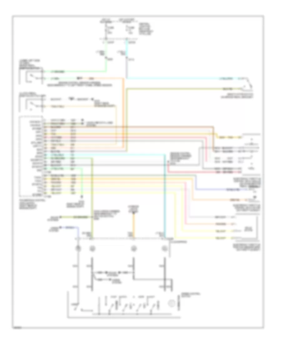
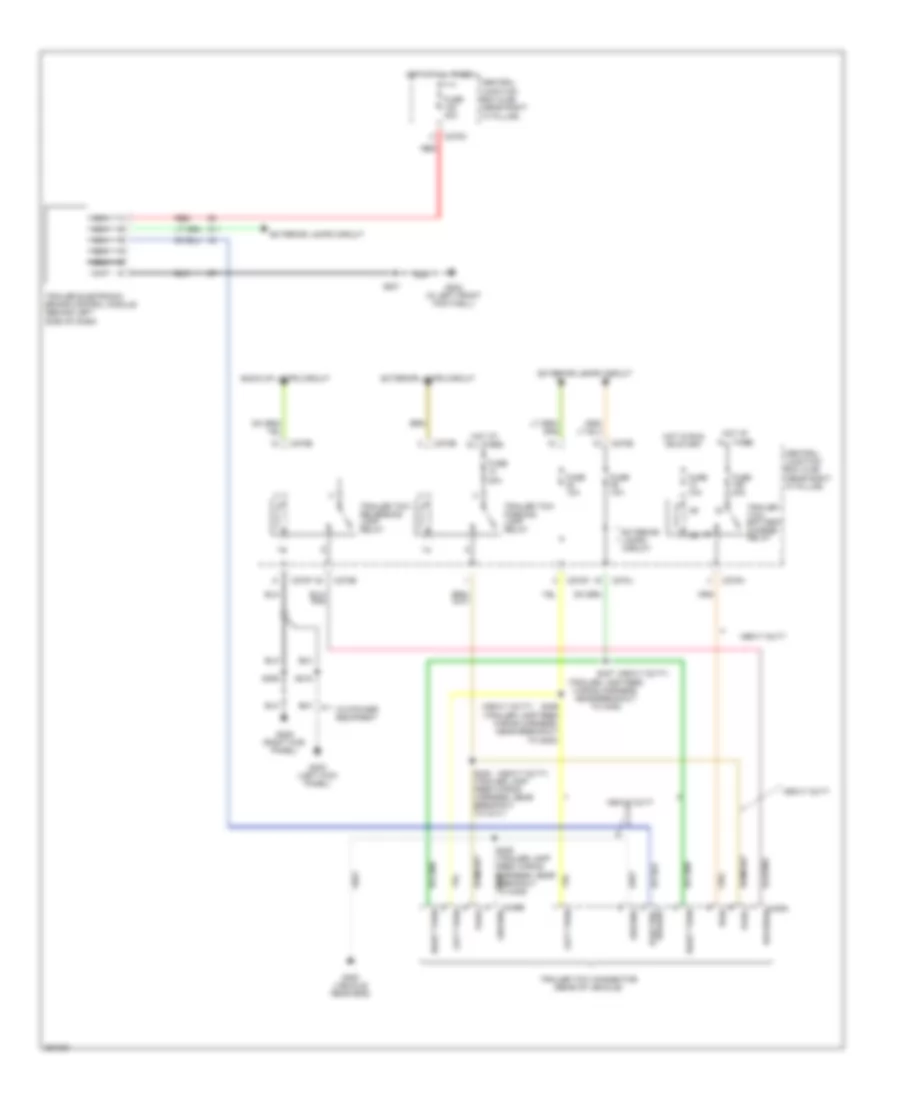
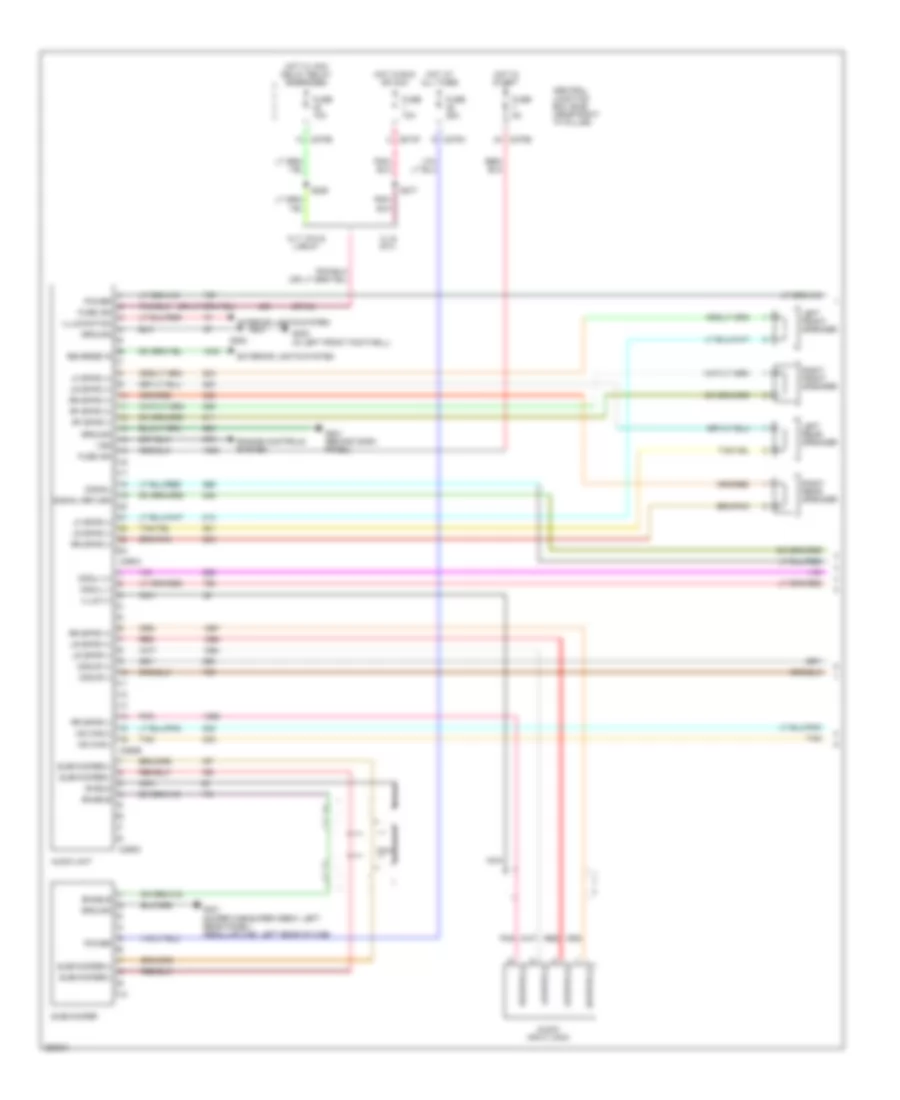
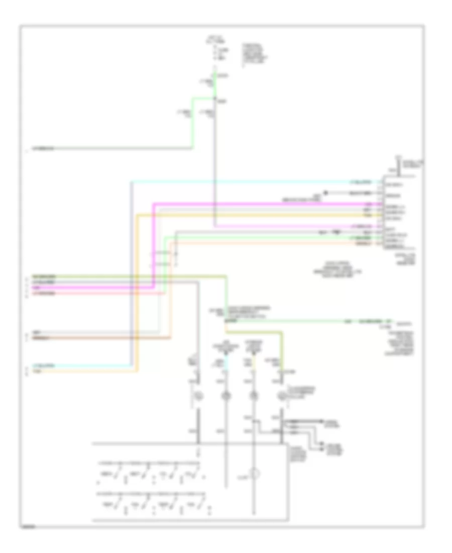
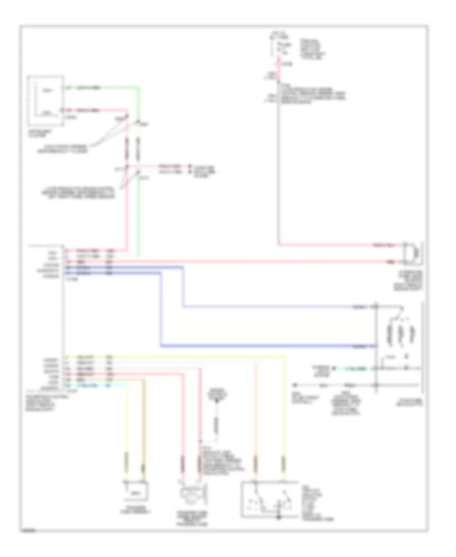
Manual A/C Wiring Diagram (1 of 2) for Ford Pickup F150 2007
List of elements for Manual A/C Wiring Diagram (1 of 2) for Ford Pickup F150 2007:
- (heater blower motor wiring harness, in breakout to c299)
- (in right front footwell) g203
- (main wiring harness, under dash, near breakout to blower motor resistor) s275
- +/-
- Ac req
- Blower motor resistor (right "a" pillar)
- C270e
- C270g
- C294a
- C294b
- Central junction box (cjb) (near right "a" pillar)
- Defogger system
- Defrost req
- Electronic manual temperature control (emtc) module (center of dash)
- Fresh/recirculation door actuator (behind right side of dash)
- Front blower motor (behind dash)
- Front blower motor relay
- Fuse 116 30a
- Fuse 13 10a
- Fuse 5 7.5a
- G200 (left "a" pillar)
- Gnd
- High
- Hot at all times
- Hot in start or run
- Illum
- Interior lights system
- Medium high
- Medium low
- Near breakout to indicator flasher relay)
- Panel mode actuator (behind center of dash)
- Rly ctrl
- S200 (main wiring harness, near breakout to passenger air bag no.1)
- S202
- S204 (heater blower motor wiring harness, in breakout to c299)
- S210 (main wiring harness, in breakout to electronic manual temperature control (emtc) module)
- S236 (main wiring harness)
- Sig
- Sig rtn
- Temperature blend door actuator (behind center of dash)
- Vbatt
- Vpwr
- Vref rear window defrost rly sw pwr
Manual A/C Wiring Diagram (2 of 2) for Ford Pickup F150 2007
List of elements for Manual A/C Wiring Diagram (2 of 2) for Ford Pickup F150 2007:
- (4.6l: engine control sensor & fuel charge harness, near breakout to a/c clutch solenoid) (5.4l: engine control sensor & fuel charge harness, near breakout to crankshaft position sensor) s122
- (engine control sensor harness, near breakout to g102)
- (engine control sensor harness, near breakout to g110) s116
- (late production: engine control sensor harness, near breakout to integrated wheel ends solenoid) (early production: engine control sensor harness, near breakout to g102)
- (right rear of engine compartment) powertrain control module (pcm)
- (top right front of engine) electronic fan clutch
- A/c pressure transducer sensor (right front of engine compartment)
- A/c clutch cycling pressure switch (right rear of engine compartment)
- A/c clutch relay
- A/c clutch solenoid (on a/c compressor)
- A/c compressor clutch diode
- Ac req
- Acpt
- Auxiliary relay box 1 (left side of engine compt)
- Breakout to a/c clutch solenoid) (5.4l: engine control sensor & fuel charge harness, near breakout to crankshaft position sensor)
- Bvref
- C175b
- C220a
- C220b
- C270a
- C270b
- Can bus +
- Can bus -
- Central junction box (cjb) (near right "a" pillar)
- Computer data lines system
- Defrost req
- Fc-v
- Fss
- Fss-gnd
- Fuse 11 10a
- Fuse 14 10a
- Fuse 32 15a
- G104 (right side of engine compartment)
- G110 (left front of engine compt)
- Hot at all times
- Hot in start or run
- Instrument cluster
- Microprocessor
- Rly ctrl
- S101 (engine control sensor harness, near breakout to auxiliary box 1)
- S104 (engine control sensor harness, near breakout to c139)
- S105
- S107
- S112
- Sig
- Sig_rtn
- Vbpwr
- Vpwr
ANTI-LOCK BRAKES
Anti-lock Brakes Wiring Diagram for Ford Pickup F150 2007
List of elements for Anti-lock Brakes Wiring Diagram for Ford Pickup F150 2007:
- (left front of engine compt) g110
- Abs control module (left front of engine compt)
- Boo
- Brake pedal position switch (under left side of dash)
- C175b
- C270b
- C270c
- C270d
- C270f
- Can+
- Can-
- Canm
- Canp
- Central junction box (cjb) (near right "a" pillar)
- Computer data
- Computer data lines system
- Diff spd sen+
- Diff spd sen-
- Ecu gnd
- Exterior lights
- Fuse 10a
- Fuse 20a
- Fuse 40a
- Fuse 5a
- G108 (left front of engine compt)
- Hot at all times
- Hot in start
- Hot in start or run
- Interior lights system
- Left front wheel speed sensor (behind left front wheel)
- Lf pwr dpvl
- Lf signal dsvl
- Lines system
- Motor gnd
- Nca
- Or run
- Powertrain control module (right rear of engine compt)
- Rear axle speed sensor (on rear axle)
- Rf pwr dpvr
- Rf signal dsvr
- Right front wheel speed sensor (behind right front wheel)
- S109 (engine control sensor harness, near breakout to left front wheel speed sensor)
- S112
- S220
- S225
- System
- Tracil
- Tracs
- Traction control switch
- Uz ign feed
- Vbatt mt feed
- Vbatt valve feed
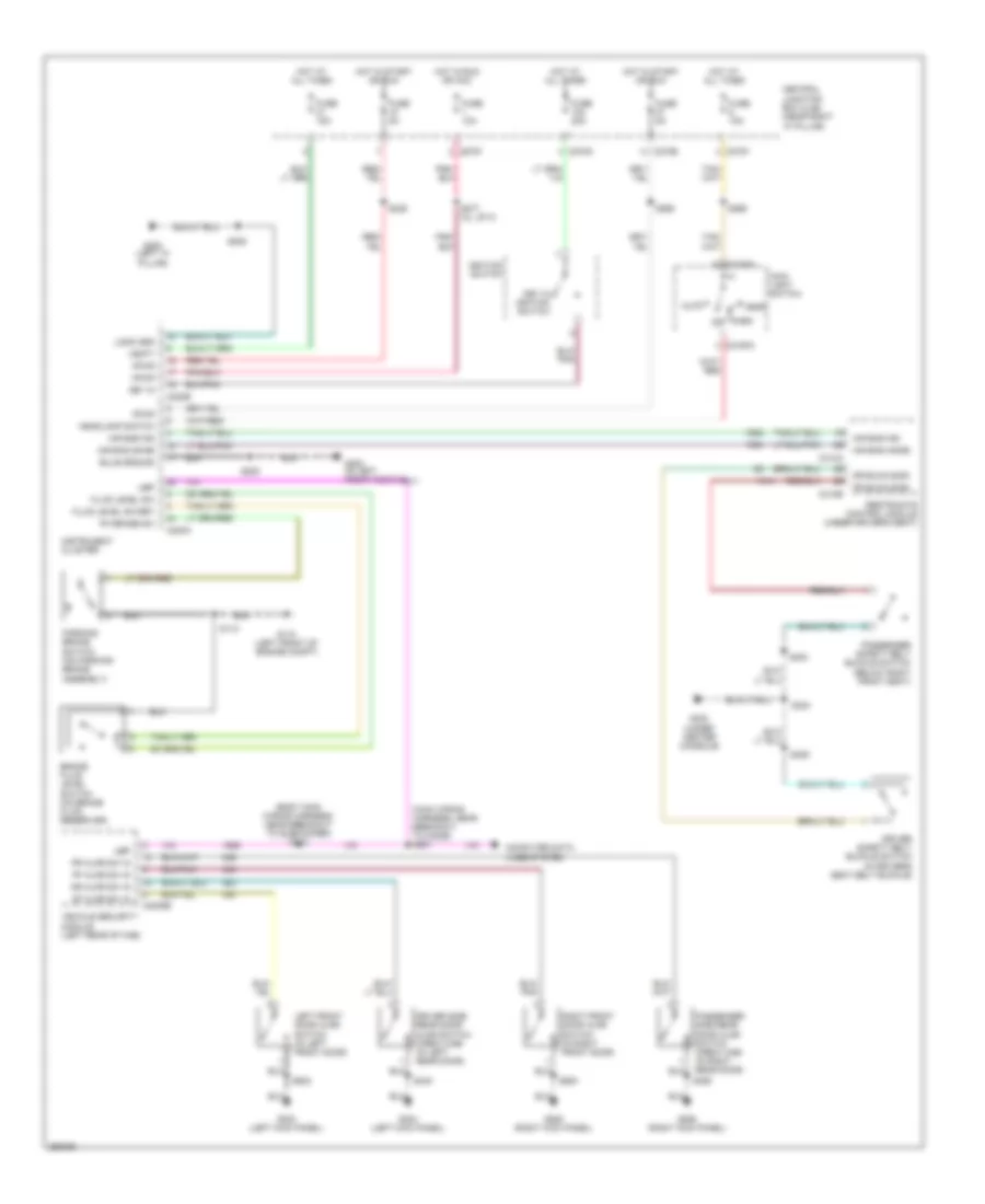
ANTI-THEFT
Forced Entry Wiring Diagram for Ford Pickup F150 2007
List of elements for Forced Entry Wiring Diagram for Ford Pickup F150 2007:
- (body main wiring harness, near breakout to c339) s342
- (in right rear door) (w/ super crew) passenger side rear door ajar switch
- (left kick panel) g303
- (regular cab: body main wiring harness, near breakout to subwoofer) (super cab/super crew: body main wiring harness, near breakout to c339)
- (regular cab: left rear of cab) (super cab/super crew: left rear panel) g300
- (right kick panel) g206
- (w/o power equipment) s216
- 1/2
- 3/4
- 5/6
- 7/8
- 9/0
- Air conditioning system
- All lock rly out
- Autolp sn
- Autolp sw in
- Batt
- C270f
- C270h
- C270j
- C270n
- C3008a
- C3008b
- Central junction box (cjb) (near right "a" pillar)
- Computer data lines system
- Df ajar sw in
- Df unlock rly out
- Dr ajar sw in
- Driver side door lock switch
- Driver side rear door ajar switch (w/ super crew) (in left rear door)
- Exterior lights system
- Fuse 10a
- Fuse 15a
- Fuse 20a
- Fuse 30a
- G303 (left kick panel)
- Hdlp pwr
- Hdlp rly out
- Headlights system
- Horn rly ctrl
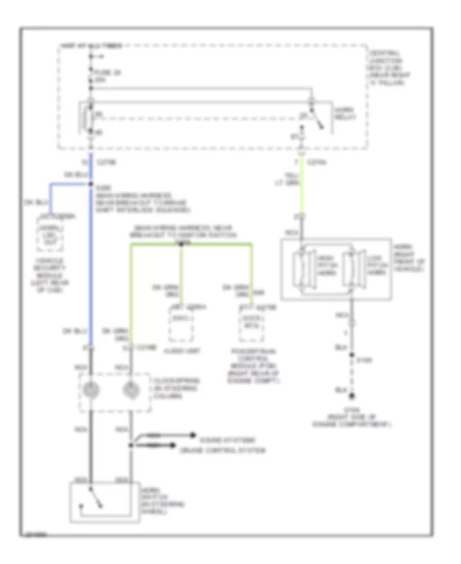
- Horns system
- Hot at all times
- Hot in run or start
- Illumination
- Interior lights system
- Keypad a sw in
- Keypad b sw in
- Keypad c sw in
- Keypad ill gnd
- Keypad ill out
- Keypad keyless entry
- Left front door ajar switch (in left front door)
- Left front door lock actuator (in left front door)
- Left rear door lock actuator (in left rear door)
- Lock
- Lock sw in
- Passenger side door lock switch
- Pf ajar sw in
- Pklp pwr
- Pklp rly out
- Pr ajar sw in
- Pwr gnd
- R/s pwr
- Red
- Right front door ajar switch (in right front door)
- Right front door lock actuator (in right front door)
- Right rear door lock actuator (in right rear door)
- S212
- S228
- S266
- S339
- S340
- S341 (body main wiring harness, near breakout to c339)
- S343
- S355
- S502
- S600
- Sig gnd
- Ubp bus
- Unlock
- Unlock rly out
- Unlock sw in
- Vehicle security module (left rear of cab)
- W/ super crew
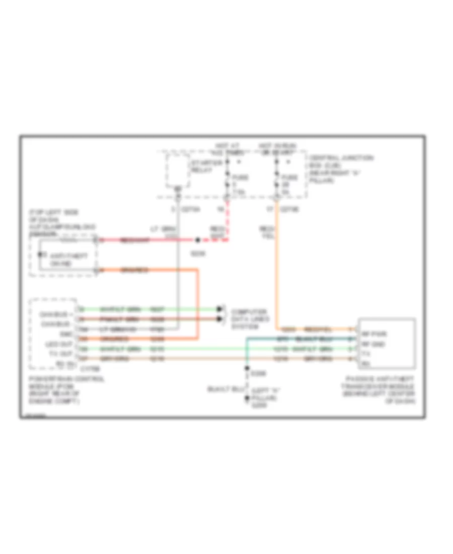
Passive Anti-theft Wiring Diagram for Ford Pickup F150 2007
List of elements for Passive Anti-theft Wiring Diagram for Ford Pickup F150 2007:
- (top left side of dash) autolamp/sunload sensor
- Anti-theft on ind
- C175b
- C270a
- C270e
- Can bus +
- Can bus -
- Central junction box (cjb) (near right "a" pillar)
- Computer data lines system
- Fuse 5a
- Fuse 7.5a
- Hot at all times
- Hot in run or start
- Led out
- Passive anti-theft transceiver module (behind left center of dash)
- Powertrain control module (pcm) (right rear of engine compt)
- Rf gnd
- Rf pwr
- Rx in
- S208
- S236
- Smc
- Starter relay
- Tx out
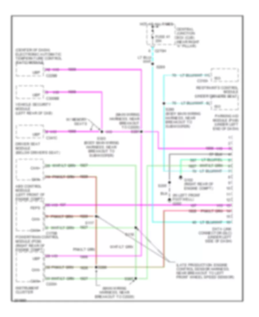
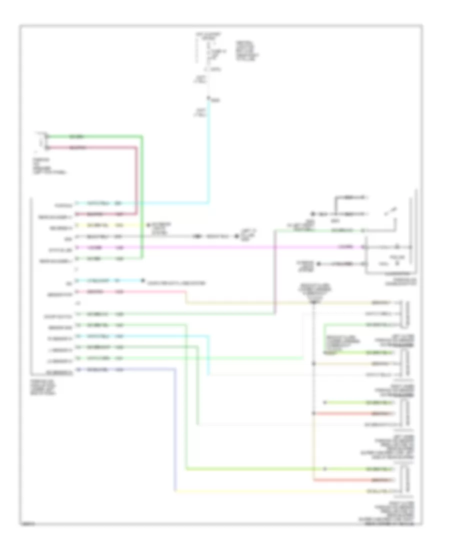
COMPUTER DATA LINES
Computer Data Lines Wiring Diagram for Ford Pickup F150 2007
List of elements for Computer Data Lines Wiring Diagram for Ford Pickup F150 2007:
- (center of dash) electronic automatic temperature control (eatc) module
- (in left front footwell) g202
- (late production: engine control sensor harness, near breakout to left front wheel speed sensor)
- (main wiring harness, near breakout to c2026)
- (main wiring harness, near breakout to c2026) s281
- Abs control module (left front of engine compt)
- C175b
- C220a
- C228b
- C270h
- C3008b
- C310a
- C341c
- Can+
- Can-
- Central junction box (cjb) (near right "a" pillar)
- Data link connector (dlc) (under left side of dash)
- Driver seat module (below driver's seat)
- Feps
- Fuse 41 20a
- G102 (right rear of engine compt)
- Hot at all times
- Instrument cluster
- Iso
- Parking aid module (pam) (under left end of dash)
- Powertrain control module (pcm) (right rear of engine compt)
- Restraints control module (under driver's seat)
- S117
- S118
- S205
- S280 (body main wiring harness, near breakout to subwoofer)
- S287
- S288
- S289
- S303 (body main wiring harness, near breakout to subwoofer)
- Ubp
- Vehicle security module (left rear of cab)
- W/ memory seats
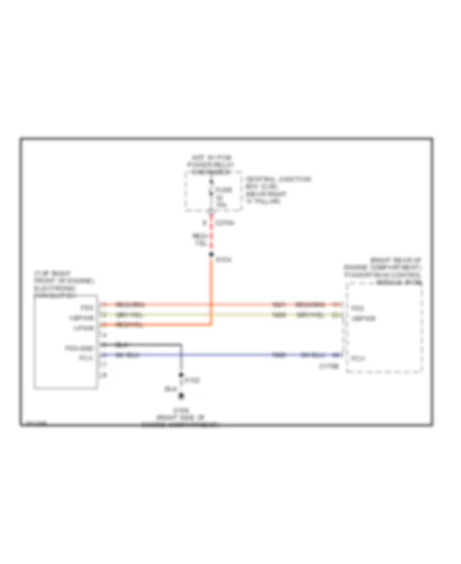
COOLING FAN
Cooling Fan Wiring Diagram for Ford Pickup F150 2007
List of elements for Cooling Fan Wiring Diagram for Ford Pickup F150 2007:
- (right rear of engine compartment) powertrain control module (pcm)
- (top right front of engine) electronic fan clutch
- C175b
- C270a
- Central junction box (cjb) (near right "a" pillar)
- Fc-v
- Fss
- Fss-gnd
- Fuse 15a
- G104 (right side of engine compartment)
- Hot w/ pcm power relay energized
- S122
- S154
- Vbpwr
- Vpwr
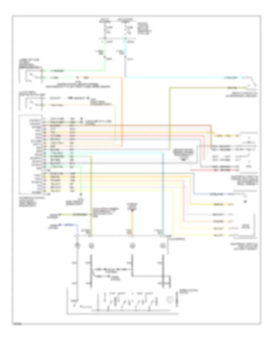
CRUISE CONTROL
4.2L
4.2L, Cruise Control Wiring Diagram for Ford Pickup F150 2007
List of elements for 4.2L, Cruise Control Wiring Diagram for Ford Pickup F150 2007:
- (engine control sensor harness, near breakout to c139) s104
- (main wiring harness, near breakout to ignition switch) s296
- (under left side of dash) brake pedal position switch
- App1
- App2
- App3
- Boo
- Bps
- C175b
- C175e
- C218b
- C270b
- C270f
- Can bus +
- Can bus -
- Cancel
- Central junction box (cjb) (near right "a" pillar)
- Clockspring
- Clutch pedal position switch (cpp)
- Computer data lines system
- Cpp-tt
- Deactivator switch (on brake pedal bracket)
- Electronic throttle control (etc) module (on accelerator pedal assembly)
- Electronic throttle position motor (on throttle body)
- Etcref
- Etcrtn
- Etc_ref
- Fuse 10a
- Fuse 20a
- G102 (right rear of engine compt)
- G103 (right rear of engine compt)
- Gnd
- Horn
- Horns system
- Hot at all times
- Hot in start or run
- Illumination
- Interior lights system
- Nca
- Powertrain control module (pcm) (right rear of engine compt)
- Resume
- S102
- S109 (engine control sensor harness, near breakout to left front wheel speed sensor)
- S112
- S220
- Sccs
- Sccsrtn
- Set +
- Set -
- Sig rtn
- Solid state
- Sound systems
- Speed control switch
- Tacm+
- Tacm-
- Tan
- Tp1
- Tp2
4.6L
4.6L, Cruise Control Wiring Diagram for Ford Pickup F150 2007
List of elements for 4.6L, Cruise Control Wiring Diagram for Ford Pickup F150 2007:
- (engine control sensor harness, near breakout to c139) s104
- (engine control sensor harness, near breakout to left front wheel speed sensor)
- (main wiring harness, near breakout to ignition switch) s296
- (under left side of dash) brake pedal position switch
- App1
- App2
- App3
- Boo
- Bps
- C175b
- C175e
- C218b
- C270b
- C270f
- Can bus +
- Can bus -
- Cancel
- Central junction box (cjb) (near right "a" pillar)
- Clockspring
- Clutch pedal position switch (cpp)
- Computer data lines system
- Cpp-tt
- Deactivator switch (on brake pedal bracket)
- Electronic throttle control (etc) module (on accelerator pedal assembly)
- Electronic throttle control (etc) motor (on throttle body)
- Electronic throttle position sensor (eps) (on throttle body)
- Etcref
- Etcrtn
- Etc_ref
- Fuse 10a
- Fuse 20a
- G102 (right rear of engine compt)
- G103 (right rear of engine compt)
- Gnd
- Horn
- Horns system
- Hot at all times
- Hot in start or run
- Illumination
- Interior lights system
- Nca
- Powertrain control module (pcm) (right rear of engine compt)
- Resume
- S102
- S109
- S112
- S220
- Sccs
- Sccsrtn
- Set +
- Set -
- Sig rtn
- Solid state
- Sound systems
- Speed control switch
- Tacm+
- Tacm-
- Tan
- Tp1
- Tp2
5.4L
5.4L, Cruise Control Wiring Diagram for Ford Pickup F150 2007
List of elements for 5.4L, Cruise Control Wiring Diagram for Ford Pickup F150 2007:
- (engine control sensor harness, near breakout to c139) s104
- (engine control sensor harness, near breakout to left front wheel speed sensor)
- (main wiring harness, near breakout to ignition switch) s296
- (under left side of dash) brake pedal position switch
- App1
- App2
- App3
- Boo
- Bps
- C175b
- C175e
- C218b
- C270b
- C270f
- Can bus +
- Can bus -
- Cancel
- Central junction box (cjb) (near right "a" pillar)
- Clockspring
- Clutch pedal position switch (cpp)
- Computer data lines system
- Cpp-tt
- Deactivator switch (on brake pedal bracket)
- Electronic throttle control (etc) module (on accelerator pedal assembly)
- Electronic throttle control (etc) motor (on throttle body)
- Electronic throttle position sensor (eps) (on throttle body)
- Etcref
- Etcrtn
- Etc_ref
- Fuse 10a
- Fuse 20a
- G102 (right rear of engine compt)
- G103 (right rear of engine compt)
- Gnd
- Horn
- Horns system
- Hot at all times
- Hot in start or run
- Illumination
- Interior lights system
- Nca
- Powertrain control module (pcm) (right rear of engine compt)
- Resume
- S102
- S109
- S112
- S220
- Sccs
- Sccsrtn
- Set +
- Set -
- Sig rtn
- Solid state
- Sound systems
- Speed control switch
- Tacm+
- Tacm-
- Tan
- Tp1
- Tp2
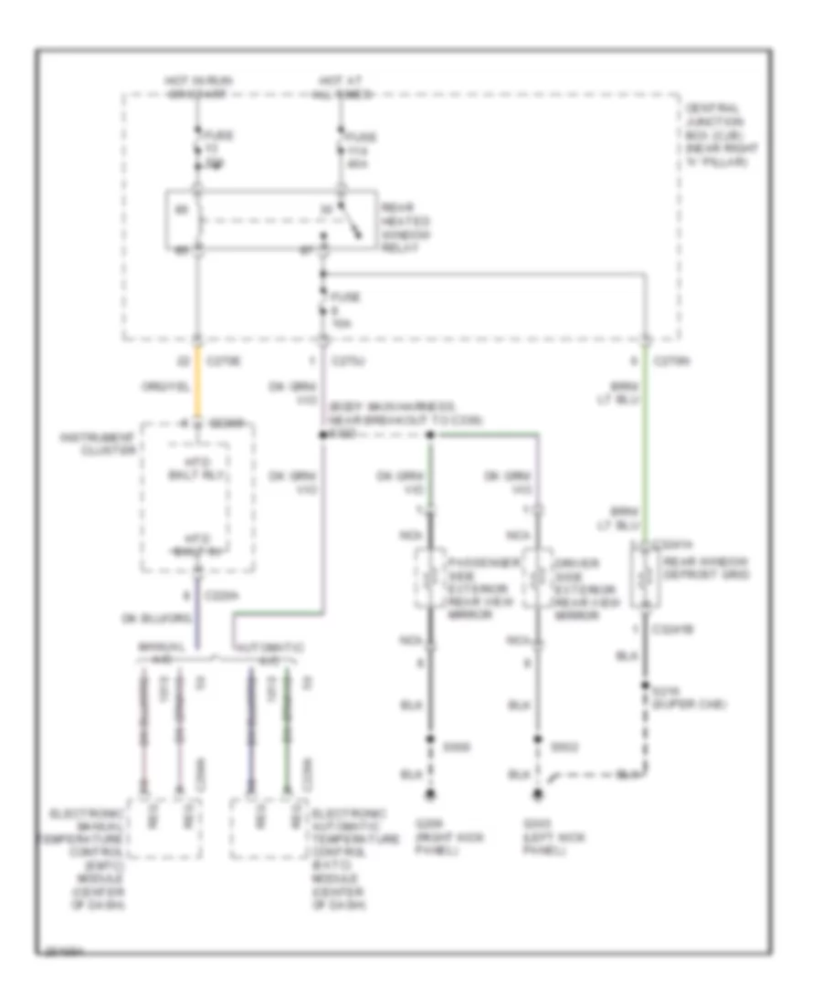
DEFOGGERS
Defoggers Wiring Diagram for Ford Pickup F150 2007
List of elements for Defoggers Wiring Diagram for Ford Pickup F150 2007:
- Automatic a/c
- C220a
- C220b
- C228a
- C270e
- C270j
- C270n
- C294a
- C3241a
- C3241b
- Central junction box (cjb) (near right "a" pillar)
- Driver side exterior rear view mirror
- Electronic automatic temperature control (eatc)
- Electronic manual temperature control (emtc) module (center of dash)
- Fuse 10a
- Fuse 40a
- G206 (right kick panel)
- G303 (left kick panel)
- Hot at all times
- Hot in run or start
- Htd bklt in
- Htd bklt rly
- Instrument cluster
- Manual a/c
- Module (center of dash)
- Nca
- Passenger side exterior rear view mirror
- Rear heated window relay
- Rear window defrost grid
- Req
- S216 (super cab)
- S502
- S600
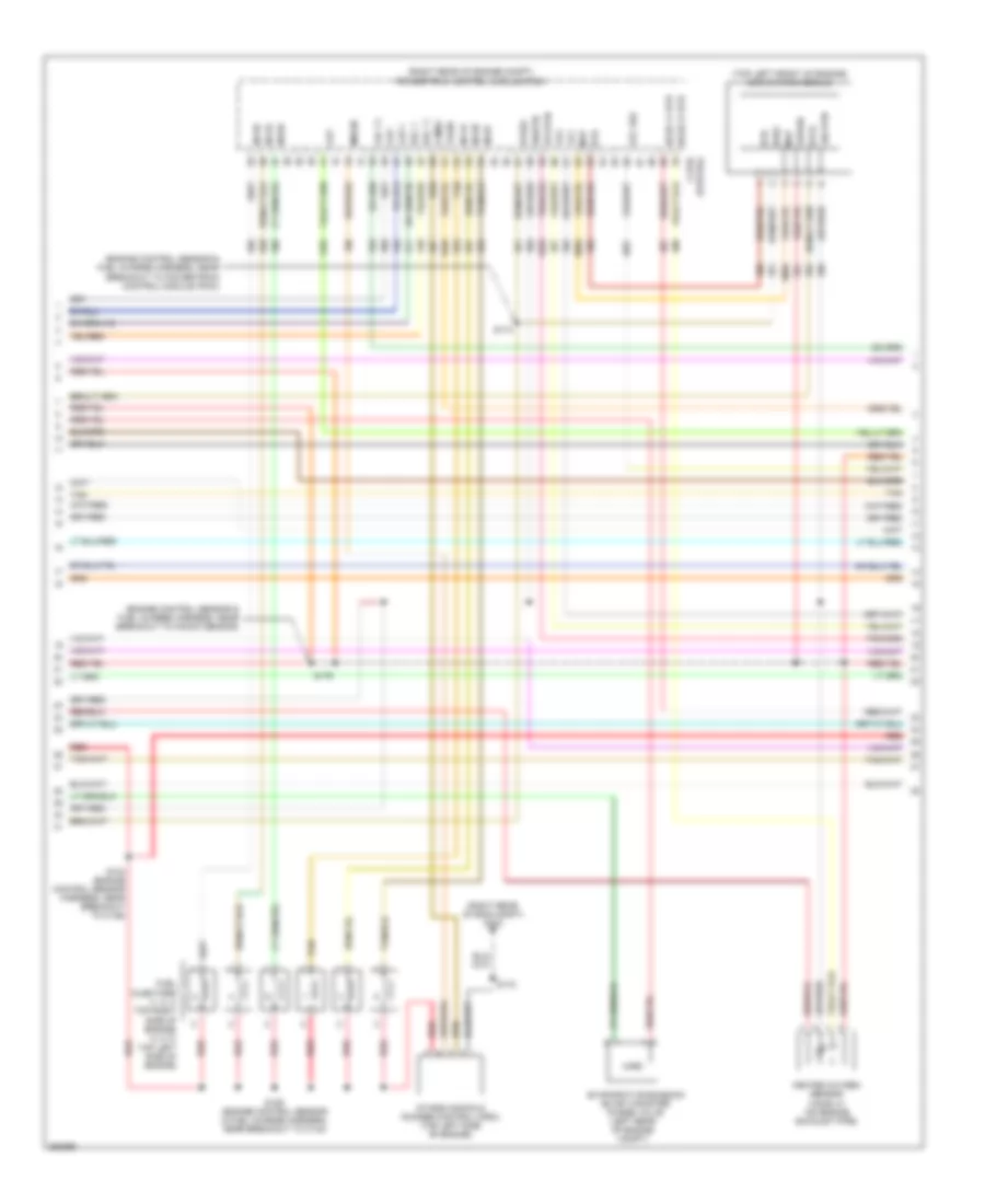
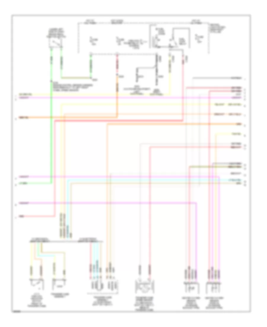
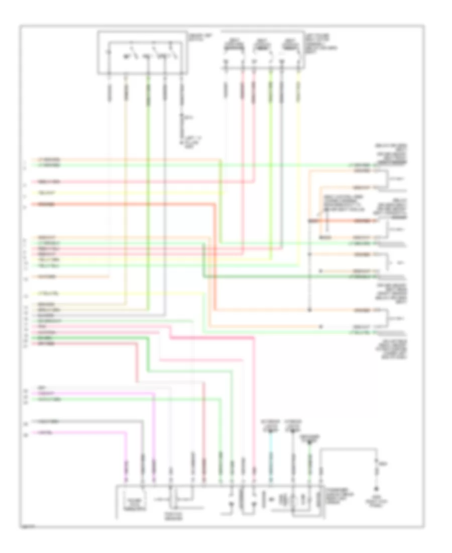
ENGINE PERFORMANCE
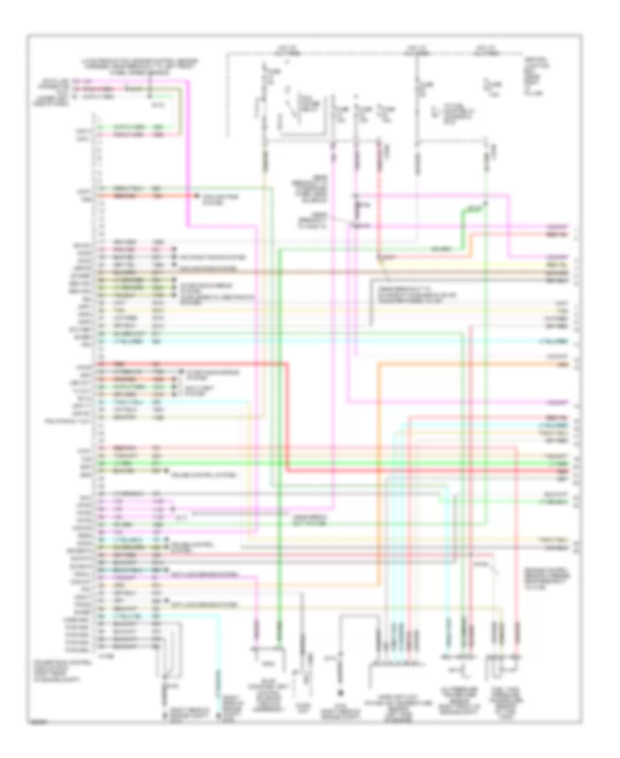
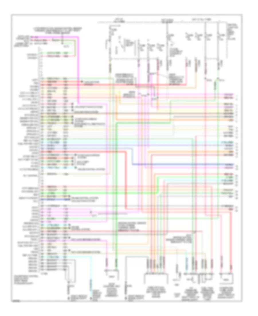
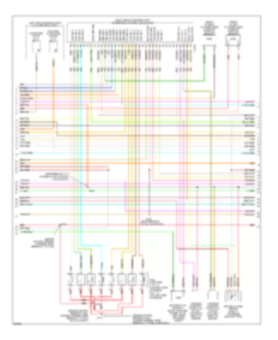
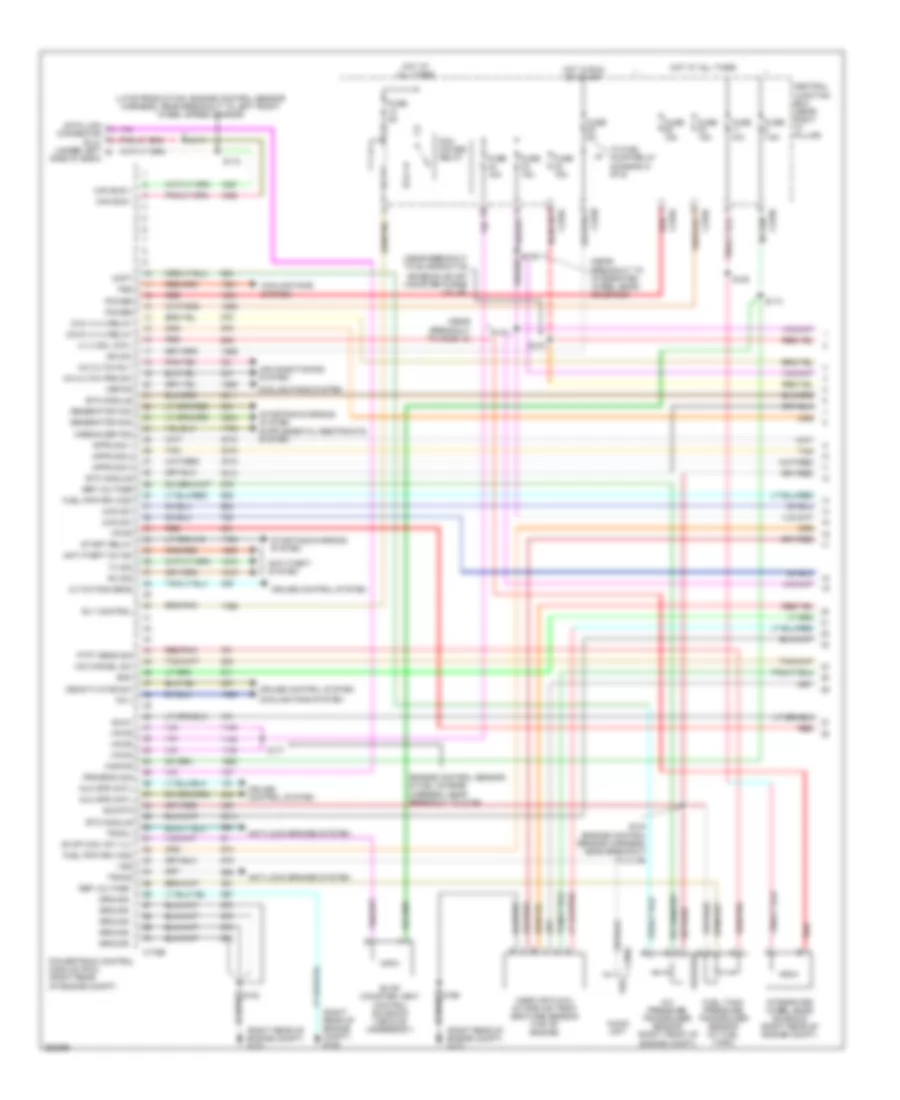
4.2L
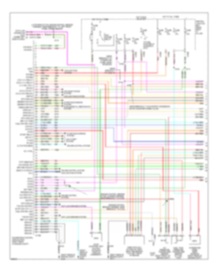
4.2L, Engine Performance Wiring Diagram (1 of 6) for Ford Pickup F150 2007
List of elements for 4.2L, Engine Performance Wiring Diagram (1 of 6) for Ford Pickup F150 2007:
- (engine control sensor harness, near breakout to c139)
- (late production: engine control sensor harness, near breakout to left front wheel speed sensor)
- (near break- out to c139)
- (near breakout to evaporative emission (evap) canister purge valve)
- (near breakout to ho2s 12)
- (near breakout to integrated wheel ends solenoid)
- (right rear of engine compt) g102
- (right rear of engine compt) g103
- A/c pressure transducer sensor (right front of engine compt)
- Accr
- Accs
- Acpt
- Air conditioning system
- Anti-lock brake system
- Anti-theft system
- App1
- App2
- App3
- Audio unit
- Boo
- Bps
- Bvref
- C175b
- C290a
- Can h
- Can l
- Canvnt
- Case gnd
- Central junction box (near right "a" pillar)
- Connector (dlc) (under left side of dash)
- Cooling fans system
- Cpp bt
- Cpp tt
- Cruise control system
- Data link
- Etc ref
- Etcref
- Etcrtn
- Evap canister vent control solenoid (vehicle underbody)
- Evm
- Feps
- Fpc
- Fpm
- Fss
- Ftpt
- Fuel tank pressure transducer sensor (at fuel tank)
- Fuse 15a
- Fuse 5a
- Fuse 7.5a
- G103 (right rear of engine compt)
- Gen com
- Gen mon
- Hot at all times
- Ign sw
- Kapwr
- Led out
- Mass air flow/ intake air temperature sensor (left side of engine)
- Pcm power relay
- Pcm pwr rly out
- Powertrain control module (pcm) (right rear of engine compt)
- Pwr gnd
- Rdi
- Red
- Red/pnk
- Rx in
- S102
- S104
- S107
- S113
- S117
- S118
- S140
- S172
- S177
- Sccs
- Sccsrtn
- Sig rtn
- Smc
- Starting/charging system
- Tan
- Tcs
- To fuel pump relay (diagram 5 of 6)
- Tracil
- Tracs
- Tx out
- Vbpwr
- Vpwr
- Vsout
- Vss
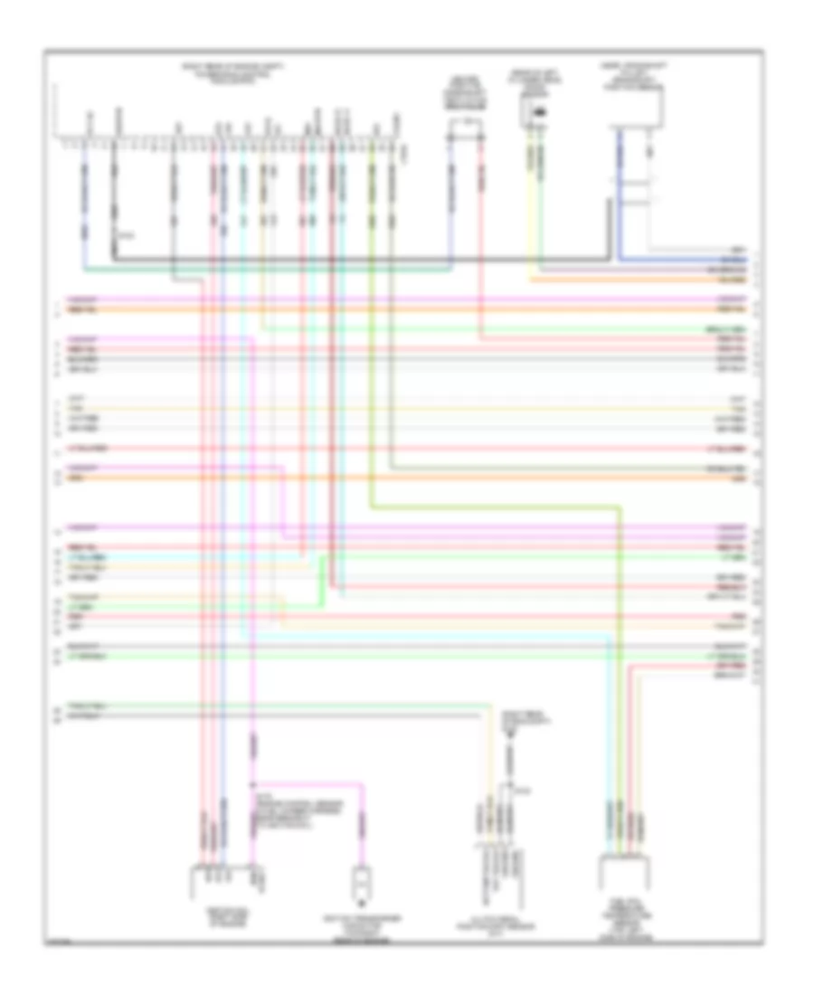
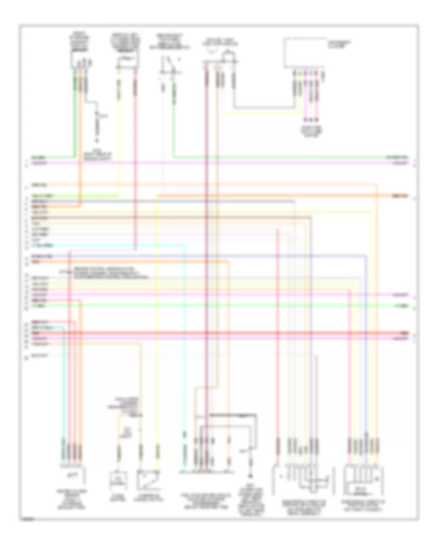
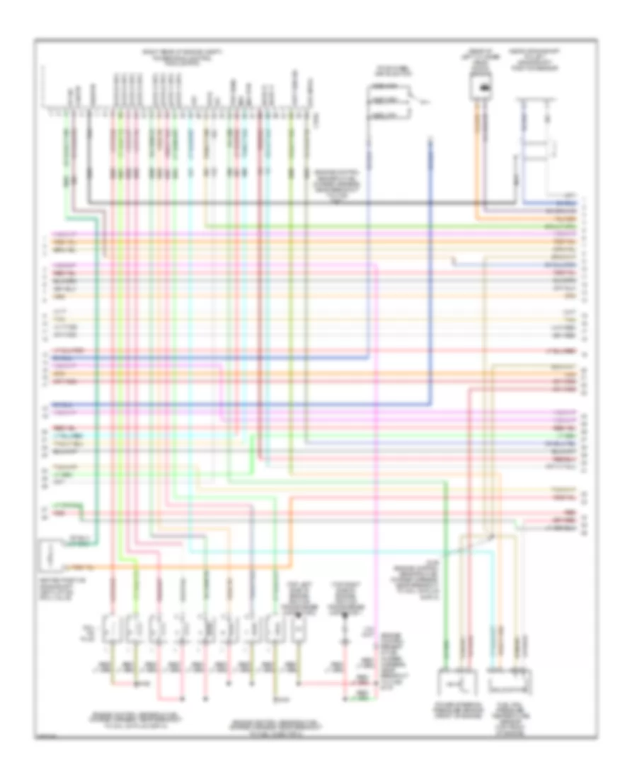
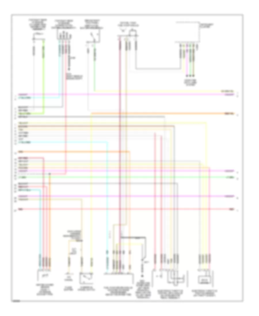
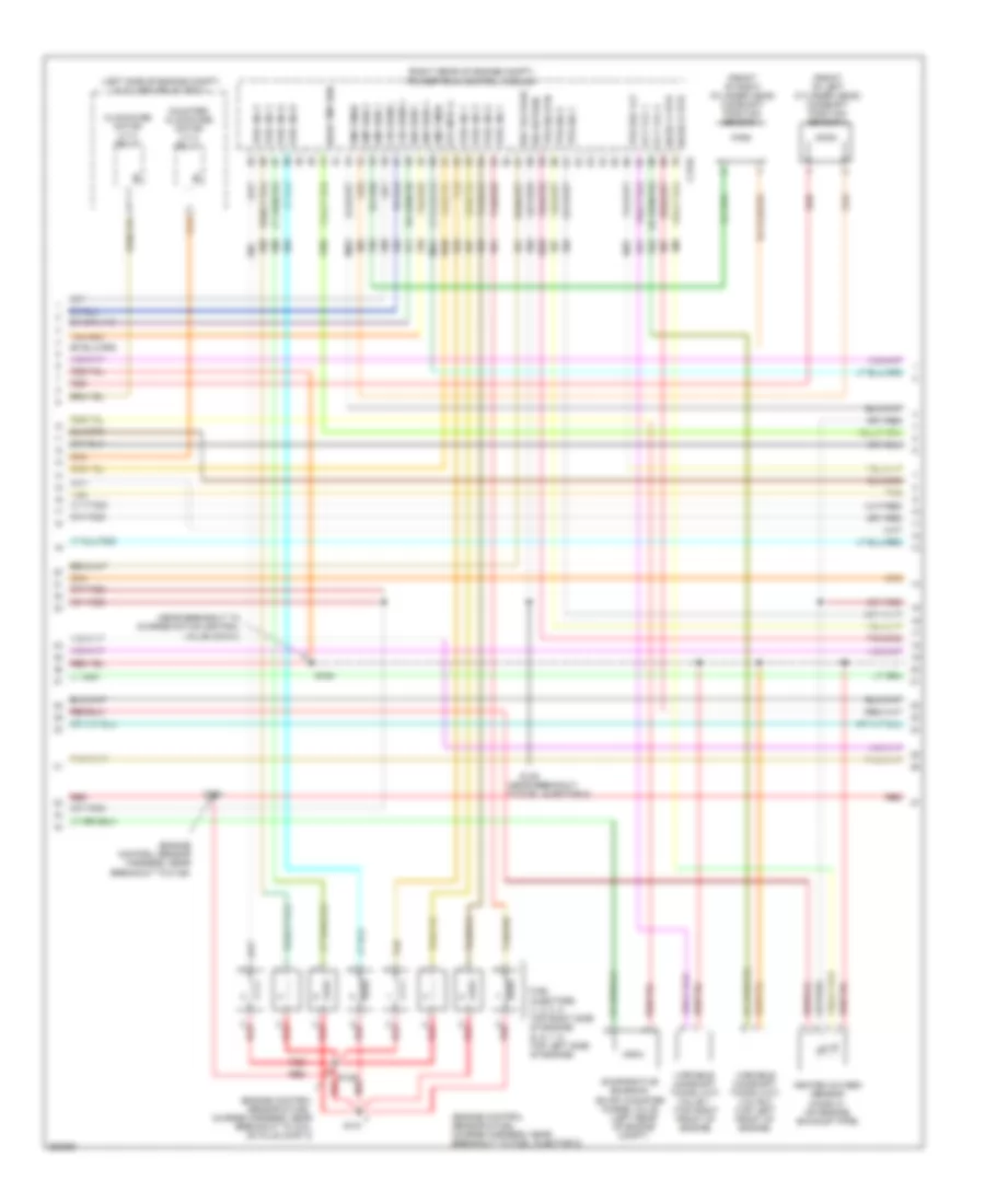
4.2L, Engine Performance Wiring Diagram (2 of 6) for Ford Pickup F150 2007
List of elements for 4.2L, Engine Performance Wiring Diagram (2 of 6) for Ford Pickup F150 2007:
- (near crankshaft pulley) crankshaft position sensor
- (rear of left cylinder head) knock sensor
- (right rear of eng compt) g103
- (right rear of engine compt) powertrain control module (pcm)
- 1a5
- 2c6
- 4b3
- Bottom travel
- C175e
- Clutch pedal position (cpp) sensor (m/t)
- Dpfe
- Frt
- Fuel rail pressure temperature sensor (top left side of engine)
- Ground
- Heated positive crankshaft ventilation (pcv) valve
- Ho2s 11
- Ho2s 21
- Iat
- Ignition coil (right side of engine)
- Ignition transformer capacitor (top right rear of engine)
- Ips
- Maf
- Mafrtn
- Nca
- Pcv hc
- Red
- Run/ start
- S102
- S123
- Shdrtn
- Tacm +
- Tan
- Top travel
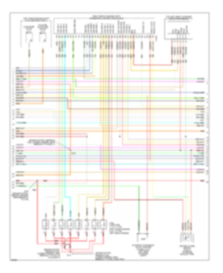
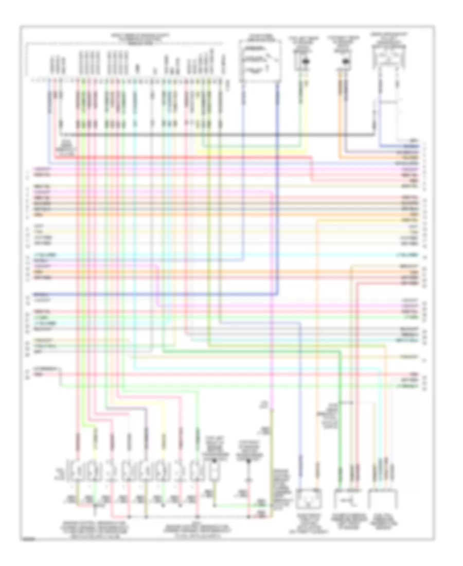
4.2L, Engine Performance Wiring Diagram (3 of 6) for Ford Pickup F150 2007
List of elements for 4.2L, Engine Performance Wiring Diagram (3 of 6) for Ford Pickup F150 2007:
- (engine control sensor & fuel charge harness, near breakout to knock sensor)
- (engine control sensor & fuel charge harness, near breakout to powertrain control module (pcm))
- (partial)
- (right rear of eng compt) g103
- (right rear of engine compt) powertrain control module (pcm)
- (top left front of engine) egr system module
- Bref
- Bvref
- C175e
- Cht
- Cid 1 v
- Ckp +
- Ckp -
- Dpfe
- E imrc
- Etc ref
- Etcrtn
- Evaporative emission (evap) canister purge valve (left rear of engine compt)
- Evr
- Fuel injectors (1, 2, 3: top right side of engine) (4, 5, 6: top left side of engine)
- Heated oxygen sensor (ho2s) 21 (on engine exhaust pipe)
- Ho2s 11 htr
- Ho2s 21 htr
- Imrcm
- Inj1a
- Inj2d
- Inj3b
- Inj4g
- Inj5f
- Inj6e
- Intake manifold runner control (imrc) (top left side of engine)
- Ksl 1 +
- Ksl 1 -
- Map
- Red
- S103 (engine control sensor harness, near breakout to c139)
- S129 (engine control sensor & fuel charge harness, near breakout to c144)
- S172
- S174
- S176
- Sig rtn
- Sigrtn
- Tacm -
- Tan
- Tp1
- Tp2
- Vbpwr
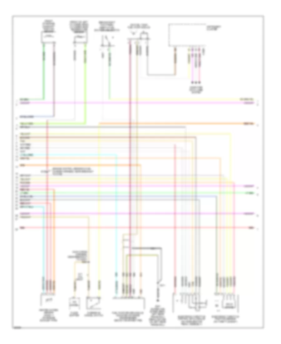
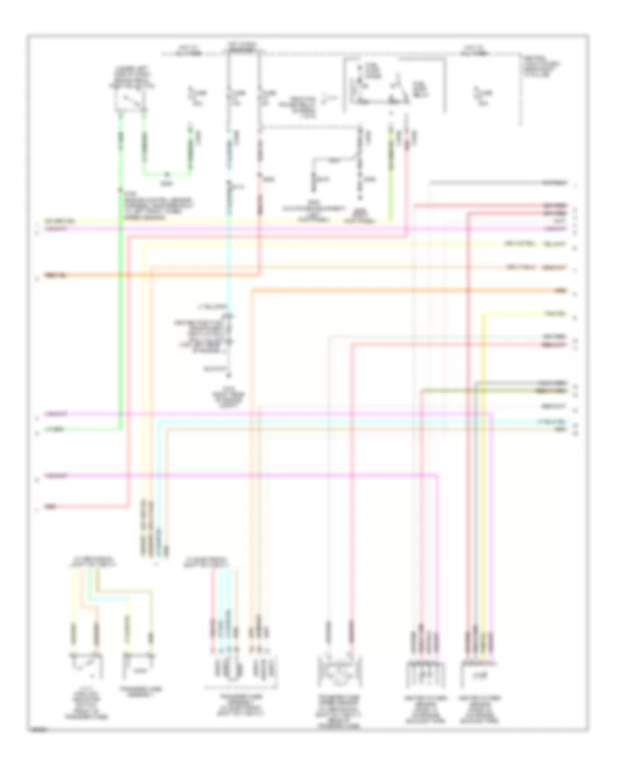
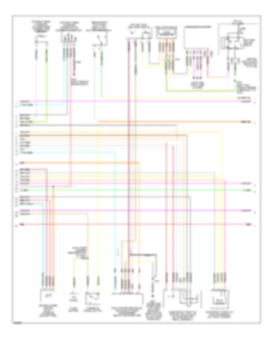
4.2L, Engine Performance Wiring Diagram (4 of 6) for Ford Pickup F150 2007
List of elements for 4.2L, Engine Performance Wiring Diagram (4 of 6) for Ford Pickup F150 2007:
- (behind right kick panel) inertia fuel shutoff (ifs) switch
- (engine control sensor & fuel
- (front of engine) camshaft position sensor
- (main wiring harness, near breakout to c3007) s284
- (on fuel tank) fuel pump module
- (rear of left cylinder head) cylinder head temperature sensor
- (super cab/ super crew: left rear frame rail) (regular cab: on left rear frame rail)
- C220a
- Cancel
- Charge harness, near breakout to powertrain control module (pcm))
- Computer data lines system
- Electronic throttle control (etc) module (on accelerator pedal assembly)
- Electronic throttle position motor (on throttle body)
- Floor shifter
- Fuel pump driver module (mounted on frame crossmember, above the spare tire)
- G103 (right rear of engine compt)
- G401
- Gnd
- Heated oxygen sensor (ho2s) 11 (on engine exhaust pipe)
- Instrument cluster
- Nca
- O/d
- Overdrive cancel switch
- Pwr
- Red
- S172
- S173
- S411
- Sig
- Solid
- State
- Tan
- Xlt, fx4, lariat
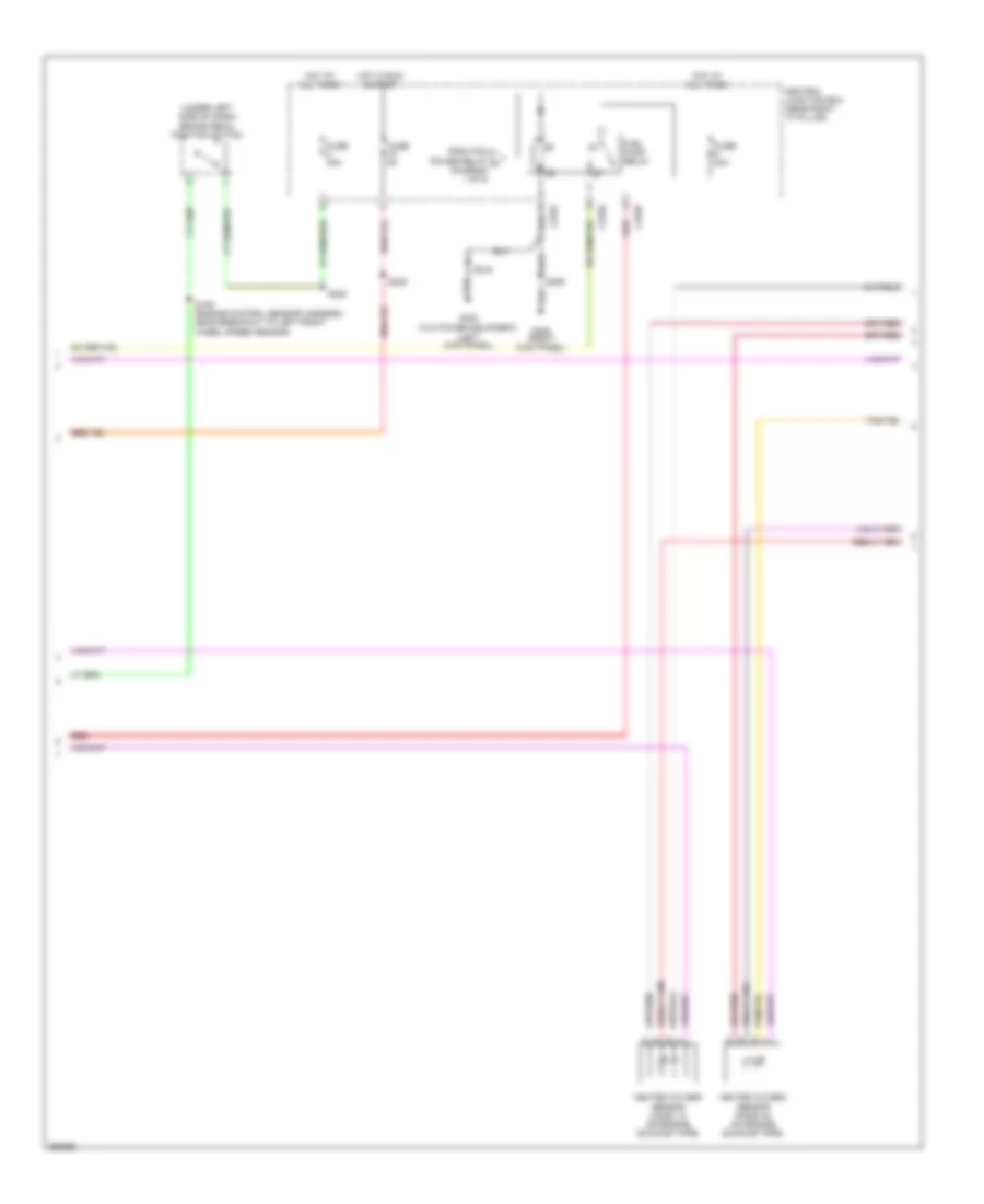
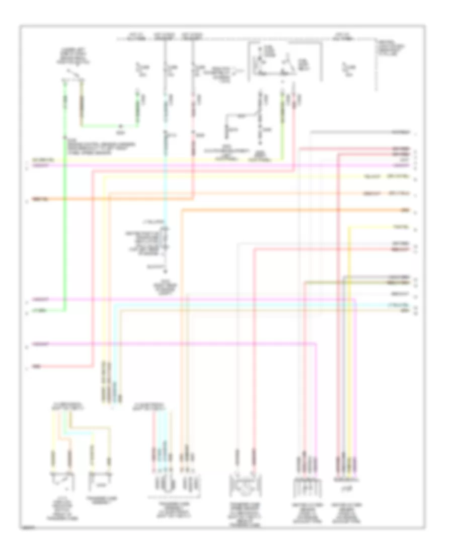
4.2L, Engine Performance Wiring Diagram (5 of 6) for Ford Pickup F150 2007
List of elements for 4.2L, Engine Performance Wiring Diagram (5 of 6) for Ford Pickup F150 2007:
- (under left side of dash) brake pedal position switch
- C270a red
- Central junction box (near right "a" pillar)
- From pcm power relay a (diagram 1 of 6)
- Fuel pump relay
- Fuse 20a
- Fuse 5a
- G206 (right kick panel)
- G303 (w/o power equipment) (left kick panel)
- Heated oxygen sensor (ho2s) 12 (on engine exhaust pipe)
- Heated oxygen sensor (ho2s) 22 (on engine exhaust pipe)
- Hot at all times
- Hot in run & start
- Red
- S109 (engine control sensor harness, near breakout to left front wheel speed sensor)
- S216
- S220
- S225
- S355
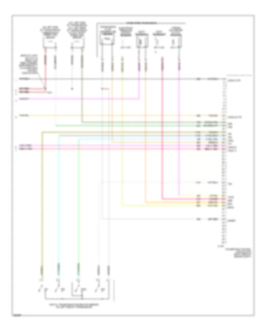
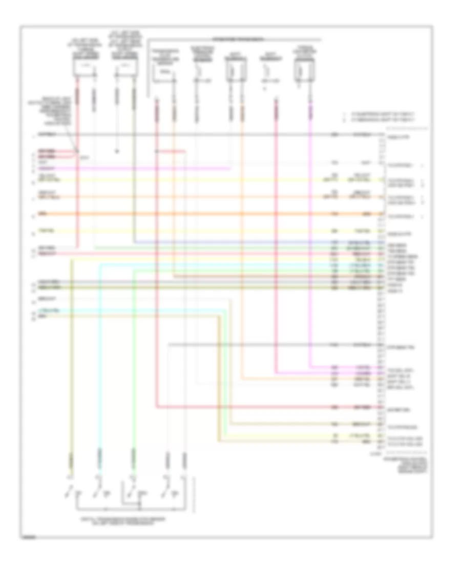
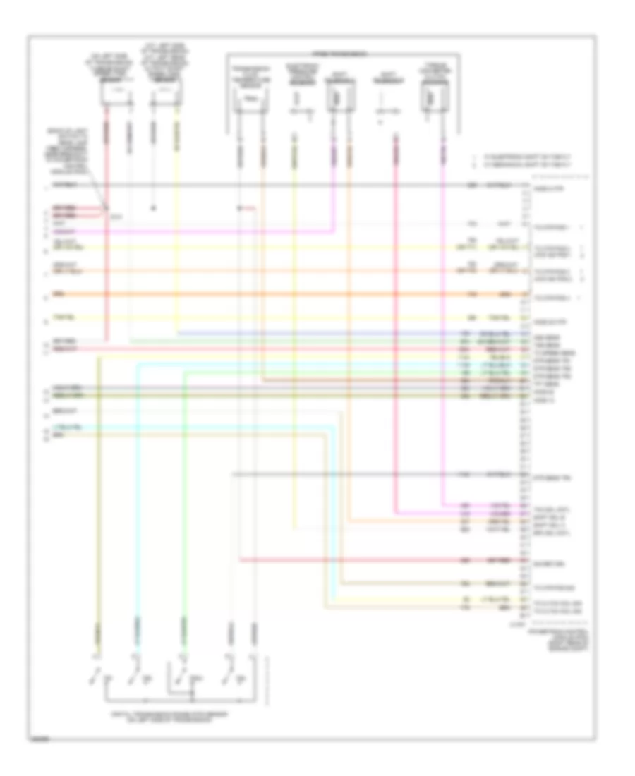
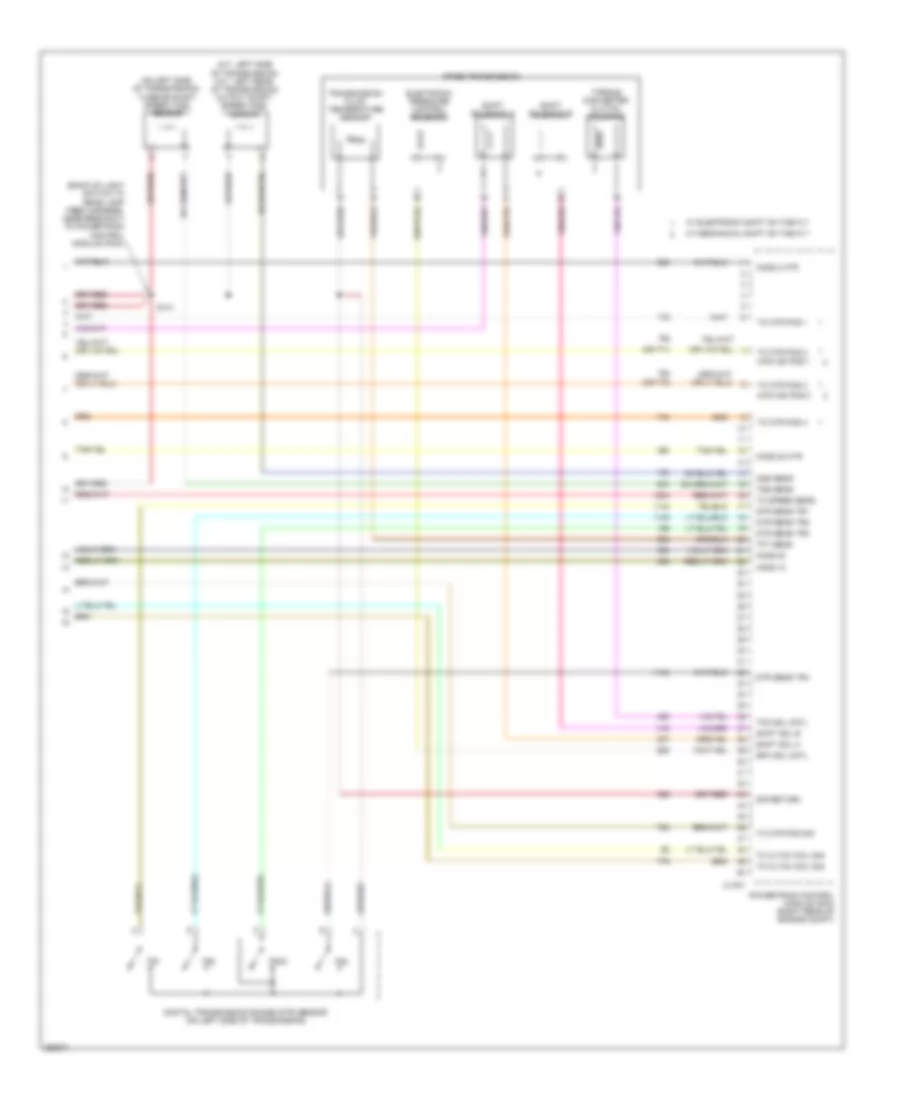
4.2L, Engine Performance Wiring Diagram (6 of 6) for Ford Pickup F150 2007
List of elements for 4.2L, Engine Performance Wiring Diagram (6 of 6) for Ford Pickup F150 2007:
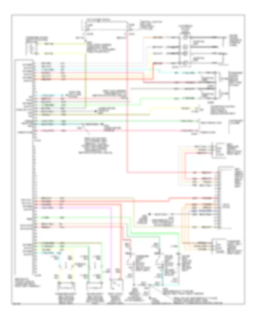
- (a/t: left side of transmission) (m/t: left rear of transmission) output shaft speed (oss) sensor
- (back-up light switch to rear lamp feed harness, near breakout to powertrain control module (pcm))
- (on left side of transmission) turbine shaft speed (tss) sensor
- 4r70e/4r75e transmission
- C175t
- Digital transmission range (dtr) sensor (on left side of transmission)
- Electronic pressure control solenoid
- Epcs
- Ho2s 12
- Ho2s 2 htr
- Ho2s 22
- Ho2s 22 htr
- Oss
- Powertrain control module (pcm) (right rear of engine compt)
- S141
- Shift solenoid a
- Shift solenoid b
- Sigret
- Ssa
- Ssb
- Tccs
- Tft
- Torque converter clutch solenoid
- Tr1
- Tr2
- Tr3a
- Tr4
- Transmission fluid temperature sensor
- Tss
4.6L
4.6L, Engine Performance Wiring Diagram (1 of 6) for Ford Pickup F150 2007
List of elements for 4.6L, Engine Performance Wiring Diagram (1 of 6) for Ford Pickup F150 2007:
- (ccw) 4 x 4 relay
- (cw) 4 x 4 relay
- (engine control sensor & fuel charge harness, near breakout to c139)
- (engine control sensor harness, near breakout to c139)
- (evap) canister purge valve)
- (late production: engine control sensor harness, near breakout to left front wheel speed sensor)
- (near breakout to evaporative emission
- (near breakout to ho2s 12)
- (near breakout to integrated wheel ends solenoid)
- (right front of
- (right rear of engine compt) g102
- (right rear of engine compt) g103
- 4 x 4 sol cntl
- 4wd sw
- A/c cltch prs sw
- A/c cltch rly
- A/c pressure transducer sensor
- Acpt
- Air conditioning system
- Airbag dep sig
- Anti-lock brakes system
- Anti-theft system
- Apps sig 1
- Apps sig 2
- Apps sig 3
- Audio unit
- Aux spd cntl
- Battery
- Brk ped pos sw
- C175b
- C270b
- C270d
- C270g
- C290a
- Can bus +
- Can bus -
- Central junction box (near right "a" pillar)
- Cltch pos sens
- Cooling fans system
- Cruise control system
- Data link connector (dlc) (under left side of dash)
- Deactivator sw
- Engine compt)
- Etc module
- Evap can vnt vlv
- Evap canister vent control solenoid (vehicle underbody)
- Evmv
- Fc-v
- Fss
- Ftpt sens sig
- Fuel pmp drv mod
- Fuel tank pressure transducer sensor (at fuel tank)
- Fuse 10a
- Fuse 15a
- Fuse 5a
- Fuse 7.5a
- Generator com
- Generator mon
- Ground
- Hot at all times
- Hot in run or start
- Ign sw
- Integrated wheel ends solenoid (right rear of engine compt)
- Led out
- Mass air flow/ intake air temp- erature sensor (top left front of engine)
- O/d cancel sw
- Pcm power relay
- Power
- Powertrain control module (pcm) (right rear of engine compt)
- Program sig
- Red
- Red/pnk
- Ref voltage
- Rly ctrl
- Rx sig
- S102
- S104
- S105
- S106
- S107
- S113
- S117
- S118
- S140
- S177
- S199
- Sig rtn
- Start relay
- Starting/charging system
- Tan
- Tcs ind control
- Tcs sw sig
- To fuel pump relay (diagram 5 of 6)
- Tx sig
- Vbpwr
- Vpwr
- Vss
4.6L, Engine Performance Wiring Diagram (2 of 6) for Ford Pickup F150 2007
List of elements for 4.6L, Engine Performance Wiring Diagram (2 of 6) for Ford Pickup F150 2007:
- (cop) 1 cntl
- (cop) 2 cntl
- (cop) 3 cntl
- (cop) 4 cntl
- (cop) 5 cntl
- (cop) 6 cntl
- (cop) 7 cntl
- (cop) 8 cntl
- (cop) 8)
- (engine control sensor & fuel charge harness, near breakout to c139) s170
- (engine control sensor & fuel charge harness, near breakout to coil on plug (cop) 8)
- (engine control sensor & fuel charge harness, near breakout to c139) s123
- (engine control sensor & fuel charge harness, near breakout to fuel injector 3)
- (near crankshaft pulley) crankshaft position sensor
- (rear of left cylinder head) knock sensor
- (right rear of engine compt) powertrain control module (pcm)
- (top left side of engine) ignition transformer capacitor 2
- (top right side of engine) ignition transformer capacitor 1
- 2wd high
- 4wd high
- 4wd low
- C175e
- Cidrtn
- Coil on plug
- Dpfe
- Etc mtr+/-
- Four-wheel drive switch
- Frpt sen sig
- Frt
- Fuel rail pressure temperature sensor (top front of engine)
- Heated positive crankshaft ventilation (pcv) valve
- Ho2s 11
- Ho2s 21
- Iat
- Maf
- Maf rtn
- Nca
- Pcvhc
- Power steering pressure sensor (front of engine)
- Psp sens
- Red
- S136 (engine control sensor & fuel charge harness, near breakout to coil on plug
- S161
- S162
- Shdrtn
- Solid state
- Tan
4.6L, Engine Performance Wiring Diagram (3 of 6) for Ford Pickup F150 2007
List of elements for 4.6L, Engine Performance Wiring Diagram (3 of 6) for Ford Pickup F150 2007:
- (engine control sensor & fuel charge harness, near breakout to coil on plug (cop) 3)
- (engine control sensor & fuel charge harness, near breakout to fuel injector 8)
- (engine control sensor & fuel charge harness, near breakout to ho2s 11)
- (left side of engine compt) auxiliary relay box 1
- (right rear of engine compt) powertrain control module (pcm)
- (top left front of engine) egr system module
- C175e
- Clockwise motor 4 x 4 relay
- Cmp sen
- Counter- clockwise motor 4 x 4 relay
- Crk sens +
- Crk sens -
- Dpfe
- Etc mtr +/-
- Evaporative emission (evap) canister purge valve (left rear of engine compt)
- Evr
- Fuel inj 1
- Fuel inj 2
- Fuel inj 3
- Fuel inj 4
- Fuel inj 5
- Fuel inj 6
- Fuel inj 7
- Fuel inj 8
- Fuel injectors (1, 2, 3, 4: top right side of engine) (5, 6, 7, 8: top left side of engine)
- Head tmp sen
- Heated oxygen sensor (ho2s) 21 (on engine exhaust pipe)
- Ho2s 11 htr
- Ho2s 21 htr
- Knk sen1 +
- Knk sen1 -
- Map
- Red
- Ref voltage
- S103 (engine control sensor harness, near breakout to c139)
- S129
- S131
- S154
- Sig return
- Sig rtn
- Tan
- Tan/red
- Tps ref vlt
- Tps sig 1
- Tps sig 2
- Tps sig rtn
- Vpwr
- Vref
4.6L, Engine Performance Wiring Diagram (4 of 6) for Ford Pickup F150 2007
List of elements for 4.6L, Engine Performance Wiring Diagram (4 of 6) for Ford Pickup F150 2007:
- (behind right kick panel) inertia fuel shutoff (ifs) switch
- (engine control sensor & fuel
- (front of engine) camshaft position sensor
- (front of left cylinder head) cylinder head temperature sensor
- (main wiring harness, near breakout to c3007) s284
- (on fuel tank) fuel pump module
- C220a
- Cancel
- Charge harness, near breakout to c139)
- Computer data lines system
- Electronic throttle control (etc) module (on accelerator pedal assembly)
- Electronic throttle position sensor (on throttle body)
- Floor shifter
- Fuel pump driver module (mounted on frame crossmember, above the spare tire)
- G401 (super cab/ super crew: left rear frame rail) (regular cab: on left rear frame rail)
- Heated oxygen sensor (ho2s) 11 (on engine exhaust pipe)
- Instrument cluster
- Nca
- O/d
- Overdrive cancel switch
- Red
- S135
- S411
- Solid
- State
- Tan
- Xlt, fx4, lariat
4.6L, Engine Performance Wiring Diagram (5 of 6) for Ford Pickup F150 2007
List of elements for 4.6L, Engine Performance Wiring Diagram (5 of 6) for Ford Pickup F150 2007:
- (diagram 1 of 6)
- (under left side of dash) brake pedal position switch
- 4 x 4 high/low indicator switch (front of transfer case)
- 4wdp1
- 4wdp2
- 4wdp3
- 4wdp4
- 4wdrtn
- C270a red
- Central junction box (near right "a" pillar)
- From pcm power relay a
- Fuel pump diode
- Fuel pump relay
- Fuse 20a
- Fuse 5a
- G206 (right kick panel)
- G303 (w/o power equipment) (left kick panel)
- Heated oxygen sensor (ho2s) 12 (on engine exhaust pipe)
- Heated oxygen sensor (ho2s) 22 (on engine exhaust pipe)
- Hot at all times
- Hot in run or start
- Red
- S109 (engine control sensor harness, near breakout to left front wheel speed sensor)
- S220
- S225
- S355
- Transfer case assembly
- Transfer case assembly (w/ electronic shift on the fly)
- Transfer case speed sensor (w/ mechanical shift on the fly) (rear of transfer case)
- W/ electronic shift on the fly
- W/ mechanical shift on the fly
4.6L, Engine Performance Wiring Diagram (6 of 6) for Ford Pickup F150 2007
List of elements for 4.6L, Engine Performance Wiring Diagram (6 of 6) for Ford Pickup F150 2007:
- (a/t: left side of transmission) (m/t: left rear of transmission) output shaft speed (oss) sensor
- (back-up light switch to rear lamp feed harness, near breakout powertrain control module (pcm))
- (on left side
- (or 771)
- (or 772)
- 4r70e/4r75e transmission
- 4wd ind pos 1
- 4wd ind pos 2
- C175t
- Digital transmission range (dtr) sensor (on left side of transmission)
- Dtr sens tr1
- Dtr sens tr2
- Dtr sens tr3
- Dtr sens tr4
- Electronic pressure control solenoid
- Epc sol cntl
- Ho2s 12
- Ho2s 2 htr
- Ho2s 22
- Ho2s 22 htr
- Of transmission)
- Oss sens
- Powertrain control module (pcm) (right rear of engine compt)
- S141
- Shift sol a
- Shift sol b
- Shift solenoid a
- Shift solenoid b
- Sig return
- Tc cltch coil sig
- Tc mtr pos 1
- Tc mtr pos 2
- Tc mtr pos 3
- Tc mtr pos 4
- Tc mtr pos sig
- Tc speed sens
- Tcc sol cntl
- Tft sens
- Torque converter clutch solenoid
- Tr1
- Tr2
- Tr3a
- Tr4
- Transmission fluid temperature sensor
- Tss sens
- Turbine shaft speed (tss) sensor
- W/ electronic shift on the fly
- W/ mechanical shift on the fly
5.4L
5.4L, Engine Performance Wiring Diagram (1 of 6) for Ford Pickup F150 2007
List of elements for 5.4L, Engine Performance Wiring Diagram (1 of 6) for Ford Pickup F150 2007:
- (ccw) 4 x 4 relay
- (cw) 4 x 4 relay
- (engine control sensor & fuel charge harness, near breakout to c139)
- (engine control sensor harness, near breakout to c139)
- (late production: engine control sensor harness, near breakout to left front wheel speed sensor)
- (near breakout to evaporative
- (near breakout to ho2s 12)
- (near breakout to integrated wheel ends solenoid)
- (right front of engine compt)
- (right rear of engine compt) g102
- (right rear of engine compt) g103
- 4 x 4 sol cntl
- 4wd sw
- A/c cltch prs sw
- A/c cltch rly
- A/c pressure transducer sensor
- Acpt
- Air conditioning system
- Airbag dep sig
- Anti-lock brakes system
- Anti-theft on ind
- Anti-theft system
- Apps sig 1
- Apps sig 2
- Apps sig 3
- Audio unit
- Aux spd cntl
- Boo
- C175b
- C270g red
- C290a
- Can bus +
- Can bus -
- Central junction box (near right "a" pillar)
- Cltch pos sens
- Cooling fans system
- Cruise control system
- Data link connector (dlc) (under left
- Deactivator sw
- Emission (evap) canister purge valve)
- Etc module
- Evap can vnt vlv
- Evap canister vent control solenoid (vehicle underbody)
- Evmv
- Fc-v
- Fss
- Ftpt sens sig
- Fuel pmp drv mod
- Fuel tank pressure transducer sensor (at fuel tank)
- Fuse 10a
- Fuse 15a
- Fuse 5a
- Fuse 7.5a
- Generator com
- Generator mon
- Ground
- Hot at all times
- Hot in run or start
- Ign sn
- Integrated wheel ends solenoid (right rear of engine compt)
- Kapwr
- Mass air flow/ intake air temp- erature sensor (top of engine)
- O/d cancel sw
- Pcm power relay
- Power
- Powertrain control module (pcm) (right rear of engine compt)
- Program sig
- Red
- Red/pnk
- Ref voltage
- Rly control
- Rx sig
- S102
- S104
- S105
- S107
- S113
- S117
- S118
- S140
- S177
- S199
- Side of dash)
- Sig rtn
- Start relay
- Starting/charging system
- Tan
- To fuel pump relay (diagram 5 of 6)
- Tracil
- Tracs
- Tx sig
- Vbpwr
- Vpwr
- Vss
5.4L, Engine Performance Wiring Diagram (2 of 6) for Ford Pickup F150 2007
List of elements for 5.4L, Engine Performance Wiring Diagram (2 of 6) for Ford Pickup F150 2007:
- (cop) 1 cntl
- (cop) 2 cntl
- (cop) 3 cntl
- (cop) 4 cntl
- (cop) 5 cntl
- (cop) 6 cntl
- (cop) 7 cntl
- (cop) 8 cntl
- (engine control sensor & fuel charge harness, near breakout to c139) s170
- (engine control sensor & fuel charge harness, near breakout
- (engine control sensor & fuel charge harness, near breakout to heated positive crankcase
- (near crankshaft pulley) crankshaft position sensor
- (right rear of engine compt) powertrain control module (pcm)
- (top left front of engine) ignition transformer capacitor 2
- (top left rear of engine)
- (top right of engine) ignition transformer capacitor 1
- (top right rear of engine) knock sensor 1
- 2wd high
- 4wd high
- 4wd low
- C175e
- Coil on plug
- Electronic throttle control (etc) motor (on throttle body)
- Etc mtr+/-
- Four-wheel drive switch
- Frpt sen sig
- Fuel rail pressure temperature sensor
- Ho2s 11
- Ho2s 21
- Iat
- Knk sen 2 +
- Knk sen 2 -
- Knock sensor 2
- Maf
- Maf rtn
- Nca
- Power steering pressure sensor (left front of engine)
- Psp sens
- Red
- S123 (near breakout to c139)
- S136 (near breakout to coil on plug (cop) 8)
- S161
- S162
- Shd rtn
- Tan
- Temp
- To coil on plug (cop) 3)
- Ventilation (pcv) valve)
- Vrsrtn 1
- Vrsrtn 2
5.4L, Engine Performance Wiring Diagram (3 of 6) for Ford Pickup F150 2007
List of elements for 5.4L, Engine Performance Wiring Diagram (3 of 6) for Ford Pickup F150 2007:
- (engine control sensor & fuel charge harness, near breakout to coil on plug (cop) 3)
- (engine control sensor & fuel charge harness, near breakout to fuel injector 8)
- (engine control sensor harness, near breakout to c139)
- (front of left cylinder head) camshaft position sensor 2
- (front of right cylinder head) camshaft position sensor 1
- (left side of engine compt) auxiliary relay box 1
- (near breakout to fuel injector 8)
- (near breakout to charge motion control valve (cmcv))
- (right rear of engine compt) powertrain control module (pcm)
- C175e
- Clockwise motor 4 x 4 relay
- Cmcv mon
- Cmp sen 1
- Cmp sen 2
- Counter- clockwise motor 4 x 4 relay
- Crk sens +
- Crk sens -
- Etc mtr +/-
- Evaporative emission (evap) canister purge valve (left rear of engine compt)
- Fuel inj 1
- Fuel inj 2
- Fuel inj 3
- Fuel inj 4
- Fuel inj 5
- Fuel inj 6
- Fuel inj 7
- Fuel inj 8
- Fuel injectors (1, 2, 3, 4: top right side of engine) (5, 6, 7, 8: top left side of engine)
- Head tmp sen
- Heated oxygen sensor (ho2s) 21 (on engine exhaust pipe)
- Ho2s 11 htr
- Ho2s 21 htr
- Knk sen1 +
- Knk sen1 -
- Red
- Ref voltage
- S103
- S129
- S131
- S135
- S154
- Sig return
- Tan
- Tan/red
- Tps ref vlt
- Tps sig 1
- Tps sig 2
- Tps sig rtn
- Variable camshaft timing (vct) valve 1 (top right front of engine)
- Variable camshaft timing (vct) valve 2 (top left front of engine)
- Vct vlv 1
- Vct vlv 2
5.4L, Engine Performance Wiring Diagram (4 of 6) for Ford Pickup F150 2007
List of elements for 5.4L, Engine Performance Wiring Diagram (4 of 6) for Ford Pickup F150 2007:
- (behind right kick panel)
- (main wiring harness, near breakout to c3007) s284
- (on fuel tank) fuel pump module
- (top right rear of engine) charge motion control valve (cmcv)
- (top right rear of engine) cylinder head temperature sensor
- C220a
- Cancel
- Cmcv
- Cmcvm
- Computer data lines system
- Electronic throttle control (etc) module (on accelerator pedal assembly)
- Electronic throttle position sensor (on throttle body)
- Floor shifter
- Fuel pump driver module (mounted on frame crossmember, above the spare tire)
- G103 (right rear of engine compt)
- G401 (super cab/ super crew: left rear frame rail) (regular cab: on left rear frame rail)
- Gnd
- Heated oxygen sensor (ho2s) 11 (on engine exhaust pipe)
- Inertia fuel shutoff (ifs) switch
- Instrument cluster
- Nca
- O/d
- Overdrive cancel switch
- Red
- S411
- Solid
- State
- Tan
- Vpwr
- Xlt, fx4, lariat
5.4L, Engine Performance Wiring Diagram (5 of 6) for Ford Pickup F150 2007
List of elements for 5.4L, Engine Performance Wiring Diagram (5 of 6) for Ford Pickup F150 2007:
- (pcv) valve (top left rear of engine)
- (under left side of dash) brake pedal position switch
- 4 x 4 high/low indicator switch (front of transfer case)
- 4wdp1
- 4wdp2
- 4wdp3
- 4wdp4
- 4wdrtn
- C270a red
- Central junction box (near right "a" pillar)
- From pcm power relay (diagram 1 of 6)
- Fuel pump diode
- Fuel pump relay
- Fuse 10a
- Fuse 20a
- Fuse 5a
- G103 (right rear of engine compt)
- G206 (right kick panel)
- G303 (w/o power equipment) (left kick panel)
- Heated oxygen sensor (ho2s) 12 (on engine exhaust pipe)
- Heated oxygen sensor (ho2s) 22 (on engine exhaust pipe)
- Heated positive crankcase ventilation
- Hot at all times
- Hot in run or start
- Red
- S109 (engine control sensor harness, near breakout to left front wheel speed sensor)
- S220
- S225
- Transfer case assembly
- Transfer case assembly (w/ electronic shift on the fly)
- Transfer case speed sensor (w/ mechanical shift on the fly) (rear of transfer case)
- W/ electronic shift on the fly
- W/ mechanical shift on the fly
5.4L, Engine Performance Wiring Diagram (6 of 6) for Ford Pickup F150 2007
List of elements for 5.4L, Engine Performance Wiring Diagram (6 of 6) for Ford Pickup F150 2007:
- (a/t: left side of transmission) (m/t: left rear of transmission) output shaft speed (oss) sensor
- (back-up light switch to rear lamp feed harness, near breakout to powertrain control module (pcm))
- (on left side of transmission) turbine shaft speed (tss) sensor
- (or 771)
- (or 772)
- 4r75e transmission
- 4wd ind pos 1
- 4wd ind pos 2
- C175t
- Digital transmission range (dtr) sensor (on left side of transmission)
- Dtr sens tr1
- Dtr sens tr2
- Dtr sens tr3
- Dtr sens tr4
- Electronic pressure control solenoid
- Epc sol cntl
- Ho2s 12
- Ho2s 2 htr
- Ho2s 22
- Ho2s 22 htr
- Oss sens
- Powertrain control module (pcm) (right rear of engine compt)
- S141
- Shift sol a
- Shift sol b
- Shift solenoid a
- Shift solenoid b
- Sig return
- Tc cltch coil sig
- Tc mtr pos 1
- Tc mtr pos 2
- Tc mtr pos 3
- Tc mtr pos 4
- Tc mtr pos sig
- Tc speed sens
- Tcc sol cntl
- Tft sens
- Torque converter clutch solenoid
- Tr1
- Tr2
- Tr3a
- Tr4
- Transmission fluid temperature sensor
- Tss sens
- W/ electronic shift on the fly
- W/ mechanical shift on the fly
5.4L FLEX FUEL
5.4L Flex Fuel, Engine Performance Wiring Diagram (1 of 6) for Ford Pickup F150 2007
List of elements for 5.4L Flex Fuel, Engine Performance Wiring Diagram (1 of 6) for Ford Pickup F150 2007:
- (ccw) 4 x 4 relay
- (cw) 4 x 4 relay
- (engine control sensor & fuel charge harness, near breakout to c139)
- (late production: engine control sensor harness, near breakout to left front wheel speed sensor)
- (near breakout to evaporative
- (near breakout to ho2s 12)
- (near breakout to integrated wheel ends solenoid)
- (right rear of engine compt) g102
- (right rear of engine compt) g103
- 4 x 4 sol cntl
- 4wd sw
- A/c cltch prs sw
- A/c cltch rly
- A/c pressure transducer sensor (right front of engine compt)
- Acpt
- Air conditioning system
- Airbag dep sig
- Anti-lock brakes system
- Anti-theft on ind
- Anti-theft system
- Apps sig 1
- Apps sig 2
- Apps sig 3
- Audio unit
- Aux spd cntl
- Boo
- C175b
- C270g red
- C290a
- Can bus +
- Can bus -
- Central junction box (near right "a" pillar)
- Cltch pos sens
- Cooling fans system
- Cruise control system
- Data link connector (dlc) (under left side of dash)
- Deactivator sw
- Emission (evap) canister purge valve)
- Etc module
- Evap can vnt vlv
- Evap canister vent control solenoid (vehicle underbody)
- Evmv
- Fc-v
- Fss
- Ftpt sens sig
- Fuel pmp drv mod
- Fuel tank pressure transducer sensor (at fuel tank)
- Fuse 10a
- Fuse 15a
- Fuse 5a
- Fuse 7.5a
- Generator com
- Generator mon
- Ground
- Hot at all times
- Hot in run or start
- Ign sw
- Integrated wheel ends solenoid (right rear of engine compt)
- Kapwr
- Mass air flow/ intake air temp- erature sensor (top of engine)
- O/d cancel sw
- Pcm power relay
- Power
- Powertrain control module (pcm) (right rear of engine compt)
- Program sig
- Red
- Red/pnk
- Ref voltage
- Rly control
- Rx sig
- S102
- S104 (engine control sensor harness, near breakout to c139)
- S105
- S107
- S113
- S117
- S118
- S140
- S177
- S199
- Sig rtn
- Start relay
- Starting/charging system
- Tan
- To fuel pump relay (diagram 5 of 6)
- Tracil
- Tracs
- Tx sig
- Vbpwr
- Vpwr
- Vss
5.4L Flex Fuel, Engine Performance Wiring Diagram (2 of 6) for Ford Pickup F150 2007
List of elements for 5.4L Flex Fuel, Engine Performance Wiring Diagram (2 of 6) for Ford Pickup F150 2007:
- (cop) 1 cntl
- (cop) 2 cntl
- (cop) 3 cntl
- (cop) 4 cntl
- (cop) 5 cntl
- (cop) 6 cntl
- (cop) 7 cntl
- (cop) 8 cntl
- (engine control sensor & fuel charge harness, near breakout to c139) s170
- (engine control sensor & fuel charge harness, near breakout
- (engine control sensor & fuel charge harness, near breakout to heated positive crankcase
- (near breakout to c139)
- (near crankshaft pulley) crankshaft position sensor
- (right rear of engine compt) powertrain control module (pcm)
- (top left front of engine) ignition transformer capacitor 2
- (top left rear of engine)
- (top right of engine) ignition transformer capacitor 1
- (top right rear of engine) knock sensor 1
- 2wd high
- 4wd high
- 4wd low
- C175e
- Coil on plug
- Electronic throttle control (etc) motor (on throttle body)
- Etc mtr+/-
- Four-wheel drive switch
- Frpt sen sig
- Fuel rail pressure temperature sensor (top left side of engine)
- Ho2s 11
- Ho2s 21
- Iat
- Knk sen 2 +
- Knk sen 2 -
- Knock sensor 2
- Maf
- Maf rtn
- Nca
- Power steering pressure sensor (left front of engine)
- Psp sens
- Red
- S123
- S136 (near breakout to coil on plug (cop) 8)
- S161
- S162
- Shdrtn
- Tan
- Temp
- To coil on plug (cop) 3)
- Ventilation (pcv) valve)
- Vrsrtn 1
- Vrsrtn 2
5.4L Flex Fuel, Engine Performance Wiring Diagram (3 of 6) for Ford Pickup F150 2007
List of elements for 5.4L Flex Fuel, Engine Performance Wiring Diagram (3 of 6) for Ford Pickup F150 2007:
- (engine control sensor & fuel charge harness, near breakout to coil on plug (cop) 3)
- (engine control sensor & fuel charge harness, near breakout to fuel injector 8)
- (engine control sensor harness, near breakout to c139)
- (front of left cylinder head) camshaft position sensor 2
- (front of right cylinder head) camshaft position sensor 1
- (left side of engine compt) auxiliary relay box 1
- (near breakout to fuel injector 8)
- (near breakout to charge motion control valve (cmcv))
- (right rear of engine compt) powertrain control module
- C175e
- Clockwise motor 4 x 4 relay
- Cmcv mon
- Cmp sen 1
- Cmp sen 2
- Counter- clockwise motor 4 x 4 relay
- Crk sens +
- Crk sens -
- Etc mtr +/-
- Evaporative emission (evap) canister purge valve (left rear of engine compt)
- Fuel inj 1
- Fuel inj 2
- Fuel inj 3
- Fuel inj 4
- Fuel inj 5
- Fuel inj 6
- Fuel inj 7
- Fuel inj 8
- Fuel injectors (1, 2, 3, 4: top right side of engine) (5, 6, 7, 8: top left side of engine)
- Head tmp sen
- Heated oxygen sensor (ho2s) 21 (on engine exhaust pipe)
- Ho2s 11 htr
- Ho2s 21 htr
- Knk sen1 +
- Knk sen1 -
- Red
- Ref voltage
- S103
- S129
- S131
- S135
- S154
- Sig return
- Tan
- Tan/red
- Tps ref vlt
- Tps sig 1
- Tps sig 2
- Tps sig rtn
- Variable camshaft timing (vct) valve 1 (top right front of engine)
- Variable camshaft timing (vct) valve 2 (top left front of engine)
- Vct vlv 1
- Vct vlv 2
5.4L Flex Fuel, Engine Performance Wiring Diagram (4 of 6) for Ford Pickup F150 2007
List of elements for 5.4L Flex Fuel, Engine Performance Wiring Diagram (4 of 6) for Ford Pickup F150 2007:
- (behind right kick panel)
- (main wiring harness, near breakout to c3007) s284
- (on fuel tank) fuel pump module
- (top right rear of engine) charge motion control valve (cmcv)
- (top right rear of engine) cylinder head temperature sensor
- Ac/dc converter
- Battery saver relay
- C220a
- C220b
- C431
- Cancel
- Central junction box (near right "a" pillar)
- Cmcv
- Cmcvm
- Computer data lines system
- Electronic throttle control (etc) module (on accelerator pedal assembly)
- Electronic throttle position sensor (on throttle body)
- Floor shifter
- Fuel pump driver module (mounted on frame crossmember, above the spare tire)
- Fuel pump module
- Fuse 15a
- G103 (right rear of engine compt)
- G401 (super cab/ super crew: left rear frame rail) (regular cab: on left rear frame rail)
- Gnd
- Heated oxygen sensor (ho2s) 11 (on engine exhaust pipe)
- Hot at all times
- Inertia fuel shutoff (ifs) switch
- Instrument cluster
- Nca
- O/d
- Overdrive cancel switch
- Red
- S240 (body main wiring harness, in breakout to c219)
- S411
- Solid
- State
- Tan
- Vpwr
5.4L Flex Fuel, Engine Performance Wiring Diagram (5 of 6) for Ford Pickup F150 2007
List of elements for 5.4L Flex Fuel, Engine Performance Wiring Diagram (5 of 6) for Ford Pickup F150 2007:
- (pcv) valve (top left rear of engine)
- (under left side of dash) brake pedal position switch
- 4 x 4 high/low indicator switch (front of transfer case)
- 4wdp1
- 4wdp2
- 4wdp3
- 4wdp4
- 4wdrtn
- C270a red
- Central junction box (near right "a" pillar)
- From pcm power relay a (diagram 1 of 6)
- Fuel pump diode
- Fuel pump relay
- Fuse 10a
- Fuse 20a
- Fuse 5a
- G103 (right rear of engine compt)
- G206 (right kick panel)
- G303 (w/o power equipment) (left kick panel)
- Heated oxygen sensor (ho2s) 12 (on engine exhaust pipe)
- Heated oxygen sensor (ho2s) 22 (on engine exhaust pipe)
- Heated positive crankcase ventilation
- Hot at all times
- Hot in run or start
- Red
- S109 (engine control sensor harness, near breakout to left front wheel speed sensor)
- S220
- S225
- Transfer case assembly
- Transfer case assembly (w/ electronic shift on the fly)
- Transfer case speed sensor (w/ mechanical shift on the fly) (rear of transfer case)
- W/ electronic shift on the fly
- W/ mechanical shift on the fly
5.4L Flex Fuel, Engine Performance Wiring Diagram (6 of 6) for Ford Pickup F150 2007
List of elements for 5.4L Flex Fuel, Engine Performance Wiring Diagram (6 of 6) for Ford Pickup F150 2007:
- (a/t: left side of transmission) (m/t: left rear of transmission) output shaft speed (oss) sensor
- (back-up light switch to rear lamp feed harness, near breakout to powertrain control module (pcm))
- (on left side of transmission) turbine shaft speed (tss) sensor
- (or 771)
- (or 772)
- 4r75e transmission
- 4wd ind pos 1
- 4wd ind pos 2
- C175t
- Digital transmission range (dtr) sensor (on left side of transmission)
- Dtr sens tr1
- Dtr sens tr2
- Dtr sens tr3
- Dtr sens tr4
- Electronic pressure control solenoid
- Epc sol cntl
- Ho2s 12
- Ho2s 2 htr
- Ho2s 22
- Ho2s 22 htr
- Oss sens
- Powertrain control module (pcm) (right rear of engine compt)
- S141
- Shift sol a
- Shift sol b
- Shift solenoid a
- Shift solenoid b
- Sig return
- Tc cltch coil sig
- Tc mtr pos 1
- Tc mtr pos 2
- Tc mtr pos 3
- Tc mtr pos 4
- Tc mtr pos sig
- Tc speed sens
- Tcc sol cntl
- Tft sens
- Torque converter clutch solenoid
- Tr1
- Tr2
- Tr3a
- Tr4
- Transmission fluid temperature sensor
- Tss sens
- W/ electronic shift on the fly
- W/ mechanical shift on the fly
EXTERIOR LIGHTS
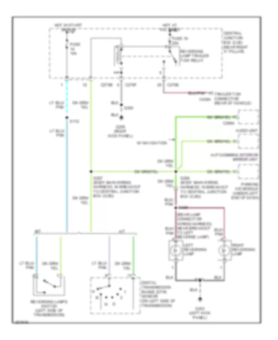
Back-up Lamps Wiring Diagram for Ford Pickup F150 2007
List of elements for Back-up Lamps Wiring Diagram for Ford Pickup F150 2007:
- (rear of vehicle)
- A/t
- Audio unit
- Auto-dimming interior mirror unit
- C270b
- C270e
- C270f
- C290a
- Central junction box (cjb) (near right "a" pillar)
- Digital transmission range (dtr) sensor (on left side of transmission)
- Fuse 10 20a
- Fuse 10a
- G206 (right kick panel)
- G303 (left kick panel)
- Hot at all times
- Hot in start or run
- Left reversing lamp
- M/t
- Parking aid module (under left end of dash)
- Reversing lamp trailer tow relay
- Reversing lamps switch (left side of transmission)
- Right reversing lamp
- S112
- S290 (body main wiring harness, in breakout to central junction box (cjb))
- S297 (body main wiring harness, in breakout to central junction box (cjb))
- S355
- S401
- S405
- To left reverse lamp)
- Trailer tow connector c439a
- W/ navigation
Exterior Lamps Wiring Diagram (1 of 2) for Ford Pickup F150 2007
List of elements for Exterior Lamps Wiring Diagram (1 of 2) for Ford Pickup F150 2007:
- (in left front footwell) g202
- Auto
- Brake pedal position switch (under left side of dash)
- C202c
- C2150a
- C220a
- C220b
- C270e
- C270f
- Central junction box (cjb) (near right "a" pillar)
- Driver side exterior rear view mirror
- Ends in harness
- Fuse 10a
- Fuse 15a
- Fuse 20a
- G104 (right side of engine compt)
- G110 (left front of engine compt)
- G202 (in left front footwell)
- G206 (right kick panel)
- G303 (left kick panel)
- Hazard
- Head
- High mounted stop lamp
- Hot at all times
- Hot in start or run
- Indicator flasher relay (behind left side of dash)
- Instrument cluster
- Interior lights system
- Left front park/ turn lamp
- Left front side lamp
- Left turn
- Left turn indicator
- Main light switch
- Microprocessor
- Multi-function switch
- Nca
- Off
- Park
- Parking lamp trailer tow relay
- Passenger side exterior rear view mirror
- Right front park/ turn lamp
- Right front side lamp
- Right turn
- Right turn indicator
- S100
- S115 (engine control sensor harness, near breakout to left front wheel speed sensor)
- S116
- S205
- S210
- S216
- S220
- S224 (main wiring harness, near breakout to indicator flasher relay)
- S231 (main wiring harness, near breakout to indicator flasher relay)
- S246 (main wiring harness, near breakout to indicator flasher relay)
- S247 (main wiring harness, near breakout to c2026)
- S266
- S355
- S502
- S600
- Trailer electronic brake control module (behind left side of dash)
- Turn signal
- W/o power equipment
Exterior Lamps Wiring Diagram (2 of 2) for Ford Pickup F150 2007
List of elements for Exterior Lamps Wiring Diagram (2 of 2) for Ford Pickup F150 2007:
- C270e
- C270j
- C270k
- C3008a
- Central junction box (cjb) (near right "a" pillar)
- Fuse 10a
- G303 (left kick panel)
- Left license plate lamp
- Left rear park/ stop/ turn lamp
- Right license plate lamp
- Right rear park/ stop/ turn lamp
- S332 (regular cab: body main wiring harness, near breakout to subwoofer) (super cab/super crew: body main wiring harness, near breakout to c313)
- S401
- S403 (rear lamp connector wiring harness, near breakout to left license plate lamp)
- Trailer/camper adapter circuit
- Vehicle security module (left rear of cab)
Trailer/Camper Adapter Wiring Diagram for Ford Pickup F150 2007
List of elements for Trailer/Camper Adapter Wiring Diagram for Ford Pickup F150 2007:
- (heavy duty)
- Back-up lamps circuit
- Brakes
- C270b
- C270e
- C270f
- C270j
- C270k
- C270n
- C439a reverse
- C439b
- Central junction box (cjb) (near right "a" pillar)
- Electric
- Exterior lamps circuit
- Fuse 10a
- Fuse 20a
- Fuse 30a
- G202 (in left front footwell)
- G206 (right kick panel)
- G303 (left kick panel)
- G400 (vehicle rear end)
- Ground
- Heavy duty
- Hot at all times
- Hot in run or start
- Left turn
- Nca
- Park
- Pwr
- Red
- Right turn
- S201
- S216
- S355
- S406 (trailer lamp feed wiring harness, near breakout to g400)
- S407 (trailer lamp feed wiring harness, near breakout to c405)
- S408 (trailer lamp feed wiring harness, near breakout to c411)
- Trailer electronic brake control module (behind left side of dash)
- Trailer tow battery charge relay
- Trailer tow connector (rear of vehicle)
- Trailer tow parking lamp relay
- Trailer tow reversing lamp relay
- W/o power equipment
GROUND DISTRIBUTION
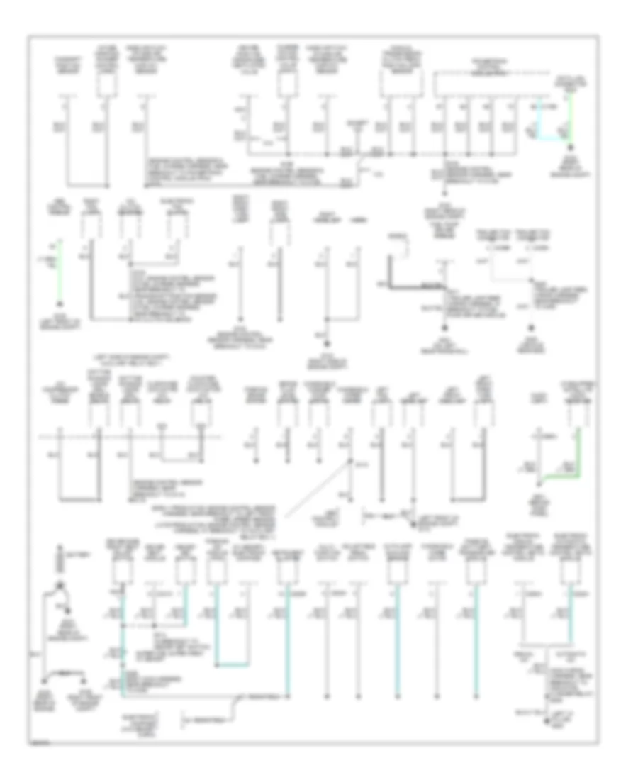
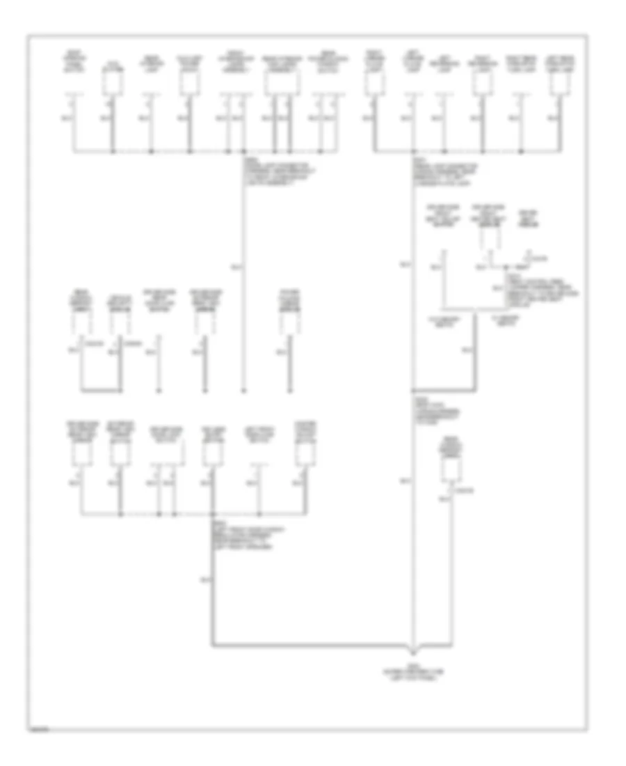
Ground Distribution Wiring Diagram (1 of 4) for Ford Pickup F150 2007
List of elements for Ground Distribution Wiring Diagram (1 of 4) for Ford Pickup F150 2007:
- (4.6l: engine control sensor & fuel charge harness, near breakout to a/c clutch solenoid)
- (early production: engine control sensor harness, near breakout to left front wheel speed sensor) (late production: engine control sensor harness, at breakout to auxiliary relay box 1)
- (engine control sensor & fuel charge harness, near breakout to powertrain control module (pcm)) s172
- (engine control sensor harness, near breakout to g110) s116
- (if equipped) satellite audio receiver
- (left "a" pillar) g200
- (left front of engine compt) g110
- (left side of engine compt) auxiliary relay box 1
- (main wiring harness, near breakout to indicator flasher relay) s208
- (manual transmission) clutch pedal position (cpp) sensor
- (w/ memory) electronic compass
- 4.2l
- 5.4l
- 87a
- A/c clutch solenoid
- A/c compressor clutch diode
- Abs control module
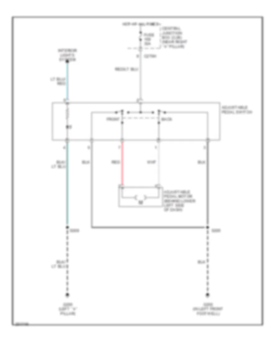
- Adjustable pedal switch
- Audio unit
- Autolamp/ sunload sensor
- Automatic a/c
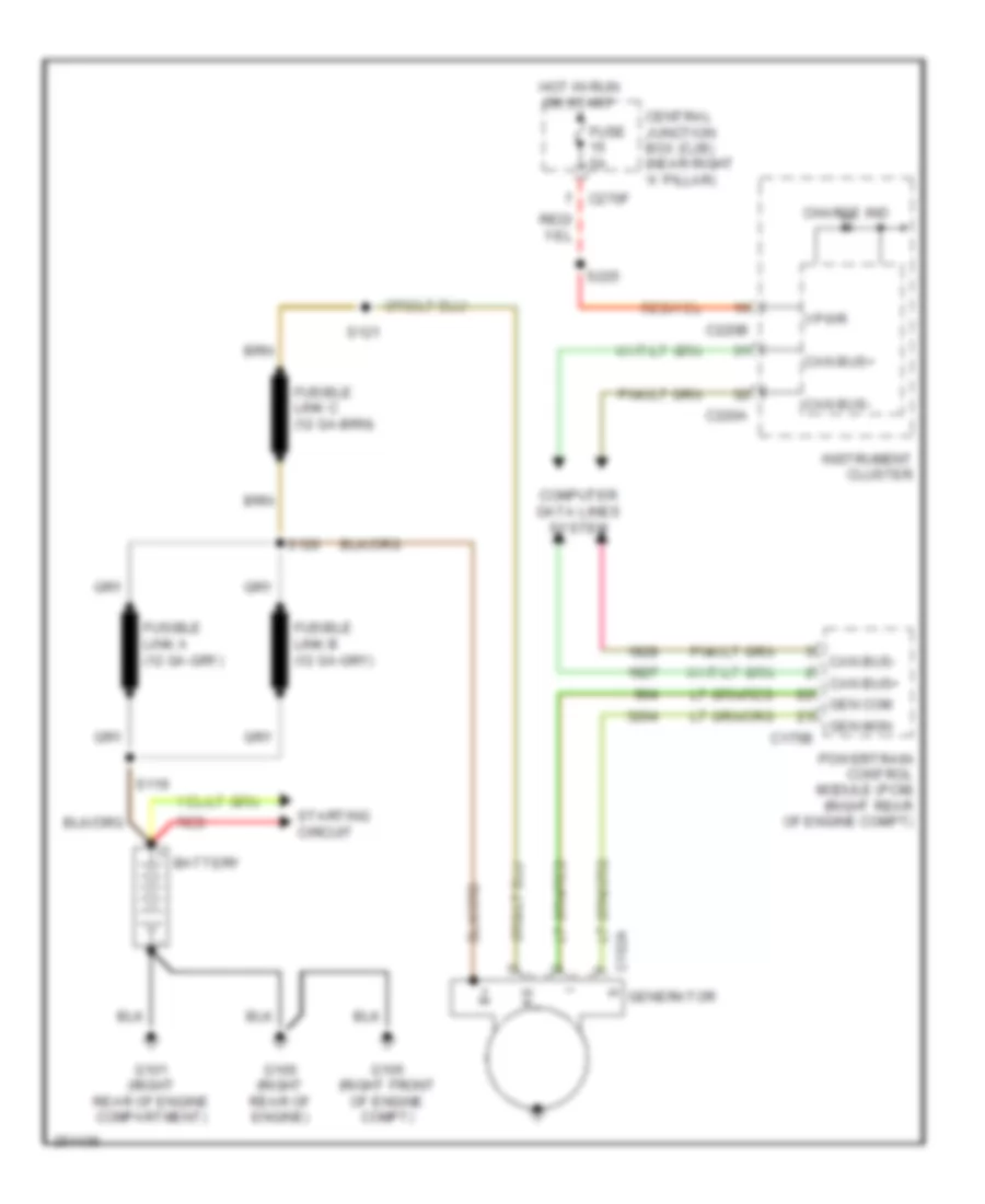
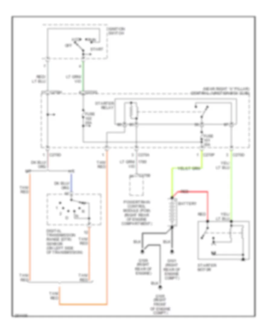
- Battery
- Brake fluid level switch
- C175b
- C202a
- C220b
- C228a
- C290a
- C294a
- C341c
- C439a
- C439b
- Camshaft position sensor
- Charge motion control valve (cmcv)
- Clockwise (cw) motor 4x4 relay
- Counter- clockwise (ccw) motor 4x4 relay
- Data link connector (dlc)
- Daytime running lamps (drl) enable relay
- Daytime running lamps (drl) relay
- Driver seat module
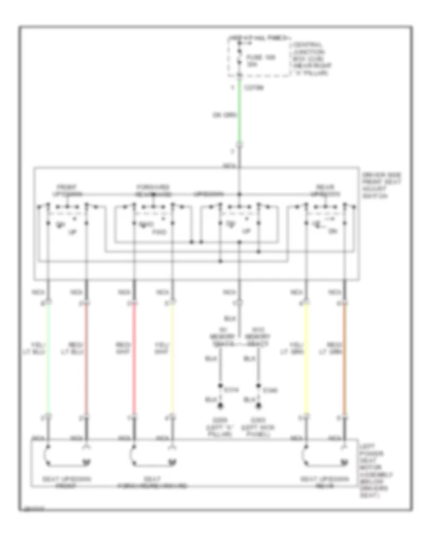
- Driver side front seat adjust switch
- Electronic automatic temperature control (eatc) module
- Electronic compass (w/o memory & rpa)
- Electronic fan clutch
- Electronic manual temperature control (emtc) module
- Except 4.2l
- Fuel pump driver module
- G100 (right rear of engine)
- G101 (right rear of engine compt)
- G102 (right rear of engine compt)
- G103 (right rear of engine compt)
- G104 (right side of engine compt)
- G105 (right front of engine compt)
- G108 (left front of engine compt)
- G201 (behind dash panel)
- G400 (vehicle rear end)
- G401 (on left rear frame rail)
- Heated positive crankcase ventilation valve
- Horn
- Instrument cluster
- Intake manifold runner control (imrc)
- Left fog lamp
- Left front park/ turn lamp
- Left front side lamp
- Left headlamp
- Manual a/c
- Mass air flow/ intake air temperature (maf/iat) sensor
- Memory set switch
- Multi- function switch
- Nca
- Parking aid module (pam)
- Parking brake switch
- Passive anti-theft transceiver module
- Powertrain control module (pcm)
- Right fog lamp
- Right front park/ turn lamp
- Right front side lamp
- Right headlamp
- S100 (engine control sensor harness, near breakout to g104)
- S110
- S199 (engine control sensor & fuel charge harness, near breakout to c139)
- S314 (in breakout to memory set switch)
- S411 (trailer lamp feed wiring harness, in breakout to fuel pump driver module)
- Shield
- Super cab, super crew w/ memory
- Trailer tow connector
- Windshield washer pump motor
- Windshield wiper motor
Ground Distribution Wiring Diagram (2 of 4) for Ford Pickup F150 2007
List of elements for Ground Distribution Wiring Diagram (2 of 4) for Ford Pickup F150 2007:
- (f-150)
- (if equipped) message center switch
- (mark lt)
- (near right "a" pillar) central junction box (cjb)
- (regular cab, super cab w/o rail system) rear interior lamp
- (w/ message center) four-wheel drive switch
- Adjustable pedal switch
- Audio unit
- Auto-dimming interior mirror unit
- Automatic a/c
- Auxiliary power point
- Battery charge trailer tow relay
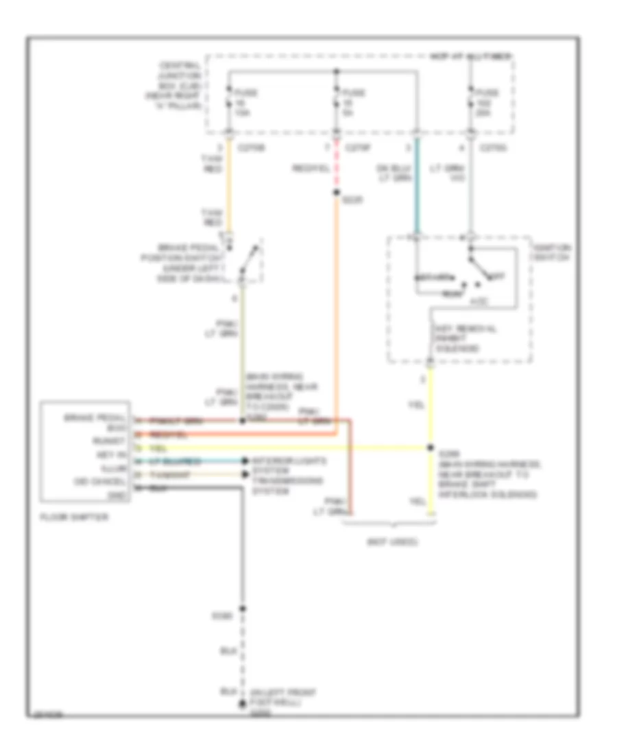
- Blower motor resistor
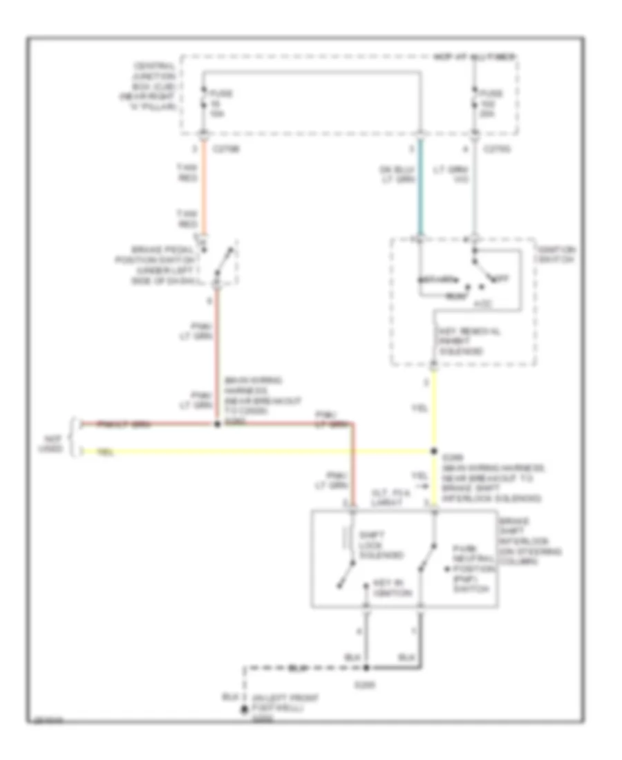
- Brake shift interlock
- C2150a
- C2150b
- C220a
- C270f
- C290a
- C294b
- C3008b
- Crew cab
- Data link connector (dlc)
- Dvd player
- Electronic manual temperature control (emtc) module
- Floor shifter
- Front blower motor speed controller
- Front cigar lighter
- Front interior/ map lamps assembly
- Fuel pump relay
- G202 (in left front footwell)
- G203 (in right front footwell)
- G206 (right kick panel)
- G300 (regular cab: left rear of cab) (except regular cab: left rear panel)
- G301 (regular cab: left rear of cab) (except regular cab: left rear panel)
- High beam relay
- High mounted stoplamp
- Indicator flasher relay
- Instrument cluster
- Instrument panel power point
- Left vanity mirror lamp
- Main light switch
- Manual a/c
- Near breakout to passenger safety belt tension sensor)
- Parking aid disable switch
- Parking lamp trailer tow relay
- Passenger side door lock switch
- Passenger side exterior rear view mirror
- Passenger side front heated seat module
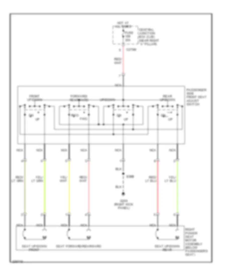
- Passenger side front seat adjust switch
- Passenger side rear door ajar switch
- Power point console 1
- Power point console 2
- Rear interior lamp
- Rear interior/ map lamps assembly
- Reversing lamp trailer tow relay
- Right front door ajar switch
- Right vanity mirror lamp
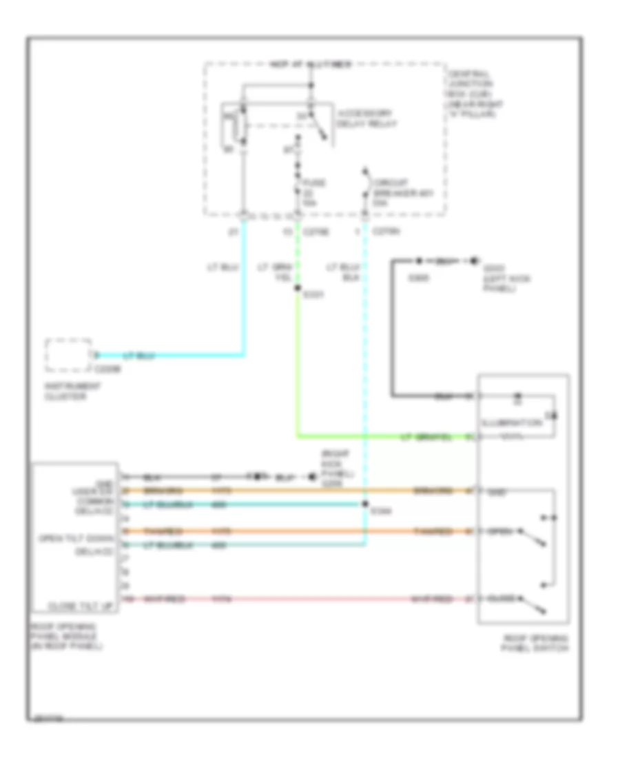
- Roof opening panel module
- S200 (main wiring harness, near breakout to passenger air bag 1)
- S201 (main wiring harness)
- S203 (main wiring harness, near breakout to front cigar lighter)
- S205 (main wiring harness, near breakout to indicator flasher relay)
- S283 (main wiring harness, near breakout to four wheel drive switch)
- S355 (body main wiring harness, near breakout to c312)
- S380 (console harness, near breakout to console 1 power point)
- S600 (right front door window regulator harness, near breakout to passenger side front power window motor)
- S905 (dome lamp connector harness, near breakout to front interior/map lights assembly)
- Subwoofer
- To splice s216 (diagram 3 of 4)
- Traction control switch
- Trailer electronic brake control module
- Vehicle security module
- W/ memory
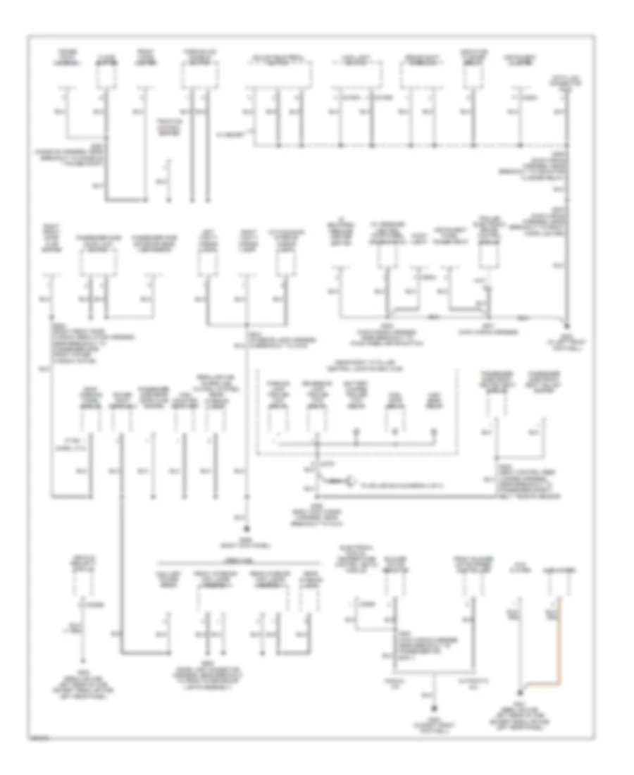
Ground Distribution Wiring Diagram (3 of 4) for Ford Pickup F150 2007
List of elements for Ground Distribution Wiring Diagram (3 of 4) for Ford Pickup F150 2007:
- (regular cab) restraints control module
- C3008a
- C310a
- C3241b
- Driver safety belt buckle switch
- Driver seat position sensor
- Driver side door lock switch
- Driver side exterior rear view mirror
- Exterior rear view mirror switch
- From central junction box (diagram 2 of 4)
- G302 (under center console)
- G303 (left kick panel)
- G303 (super cab) (left kick panel)
- High mounted stop- lamp
- Keyless entry keypad
- Left front door ajar switch
- Left license plate lamp
- Left rear park/stop/ turn lamp
- Left reversing lamp
- Master window adjust switch
- Passenger safety belt buckle switch
- Rear interior lamp
- Rear window defrost grid
- Regular cab w/ power equipment
- Regular cab w/o power equipment
- Restraints control module
- Right front door ajar switch
- Right license plate lamp
- Right rear park/stop/ turn lamp
- Right reversing lamp
- S216 (body main wiring harness, near breakout to subwoofer)
- S324 (except regular cab: body main harness, near breakout to restraints control module) (regular cab: body main harness, near breakout to c339)
- S401 (rear lamp connector wiring harness, near breakout to left license plate lamp)
- S502 (left front door window regulator harness, near breakout to left front speaker)
- Seat weight sensor module
- Vehicle security module
- W/ power equipment
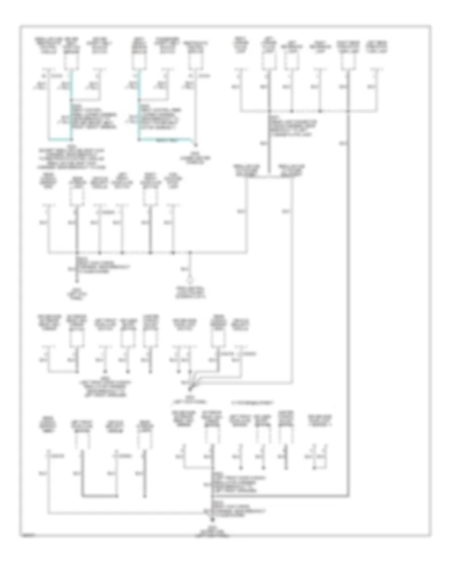
Ground Distribution Wiring Diagram (4 of 4) for Ford Pickup F150 2007
List of elements for Ground Distribution Wiring Diagram (4 of 4) for Ford Pickup F150 2007:
- Auxiliary power point
- Breakout to driver side front heated seat module)
- C3008a
- C3241b
- C341b
- Driver seat module
- Driver side door lock switch
- Driver side exterior rear view mirror
- Driver side front heated seat module
- Driver side front seat adjust switch
- Driver side rear door ajar switch
- Dvd player
- Exterior rear view mirror switch
- Front interior/map lamps assembly
- G303 (super cab/crew cab) (left kick panel)
- Keyless entry keypad
- Left front door ajar switch
- Left license plate lamp
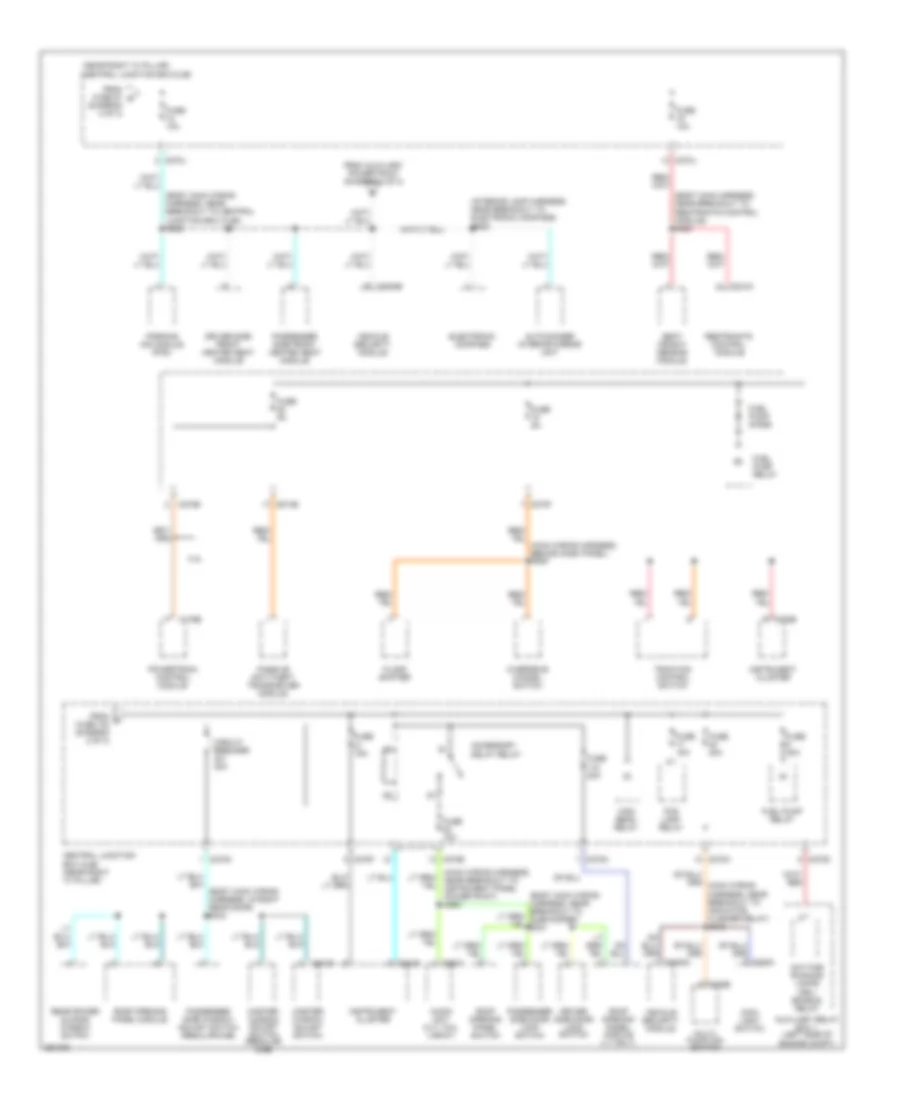
- Left rear park/stop turn lamp
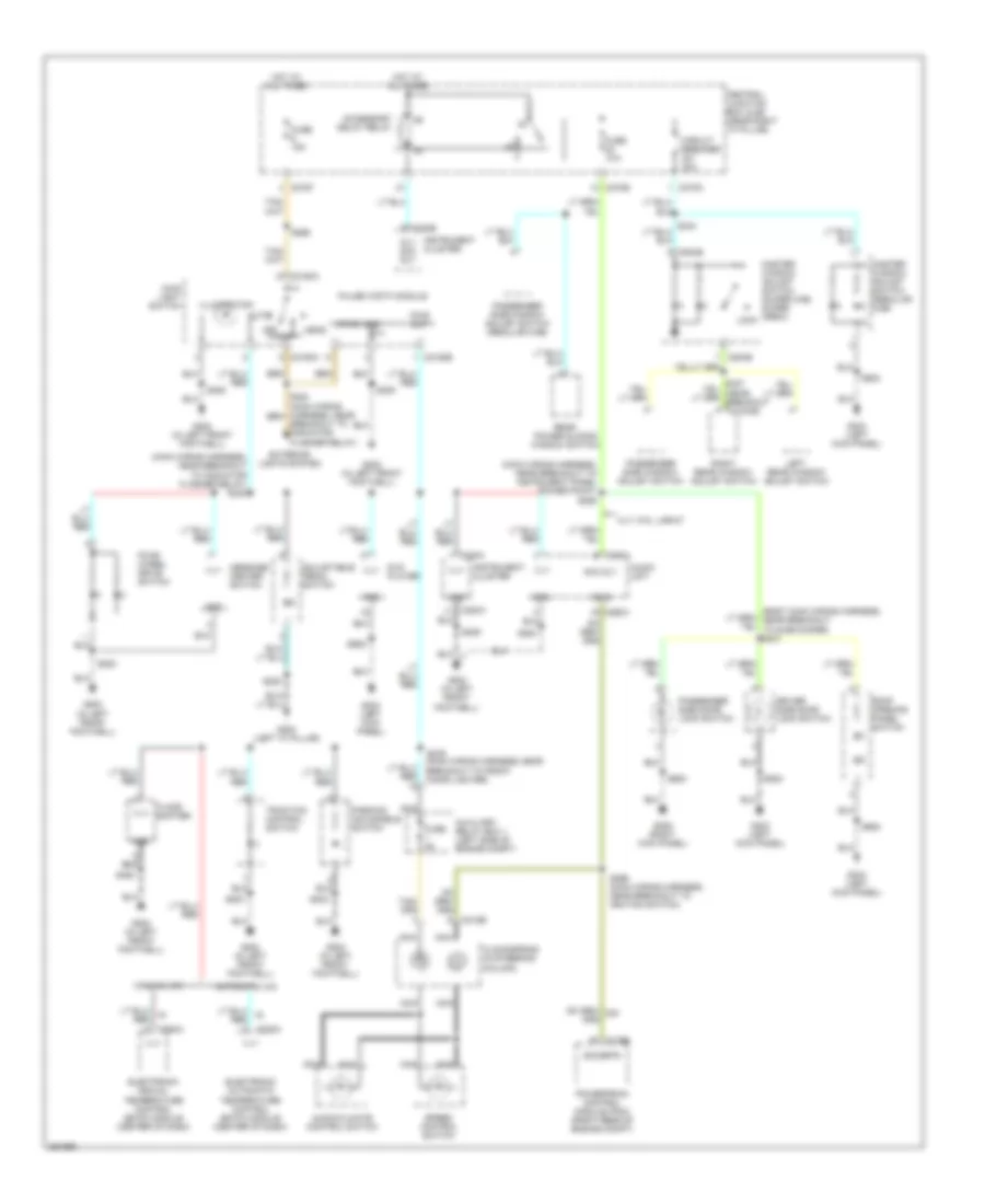
- Left reversing lamp
- Master window adjust switch
- Power folding mirror module
- Rear interior lamp
- Rear interior/ map lamps assembly
- Rear power sliding window switch
- Rear window defrost grid
- Right license plate lamp
- Right rear park/stop turn lamp
- Right reversing lamp
- Roof opening panel switch
- S340 (body main wiring harness, near breakout to c339)
- S401 (rear lamp connector wiring harness, near breakout to left license plate lamp)
- S502 (left front door window regulator harness, near breakout to left front speaker)
- S905 (dome lamp connector harness, near breakout to front interior/map lights assembly)
- Vehicle security module
- W/ memory seats
- W/o memory seats
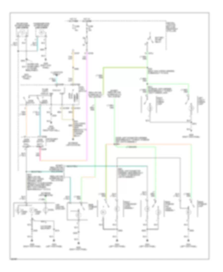
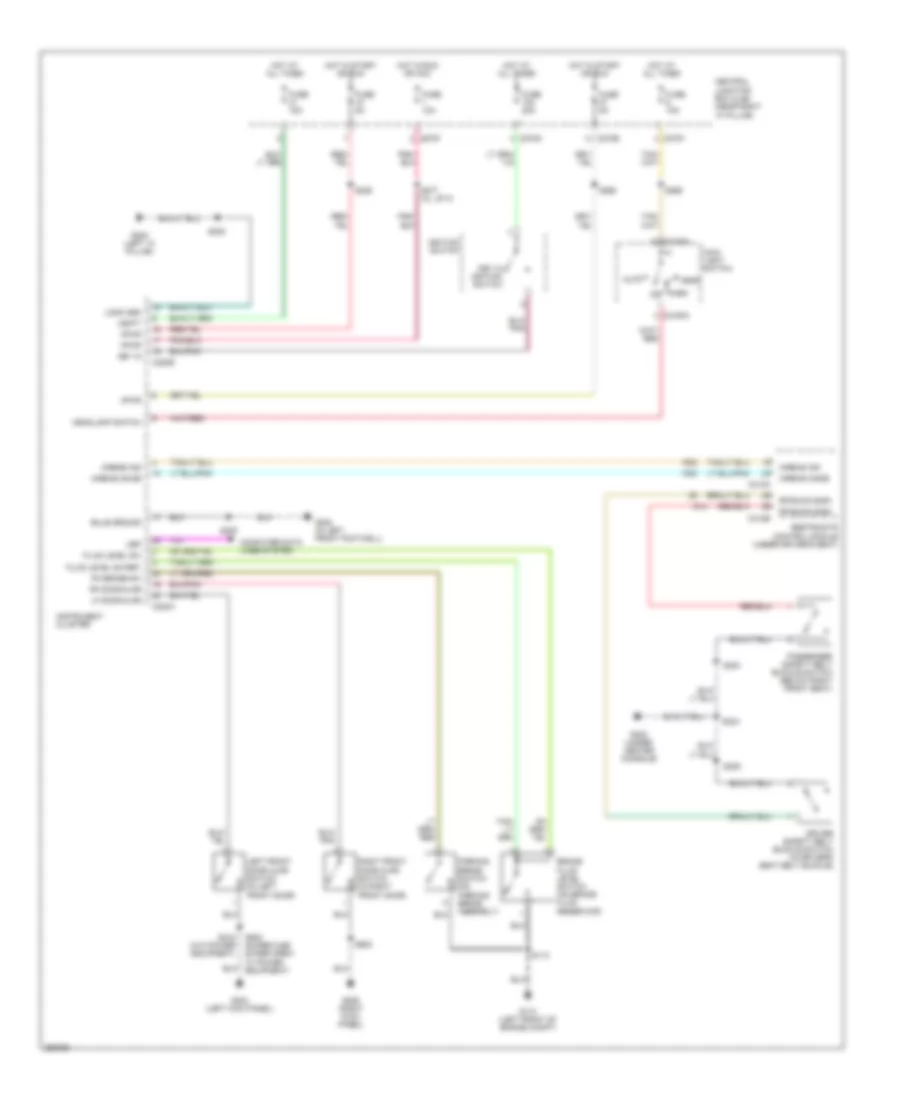
HEADLIGHTS
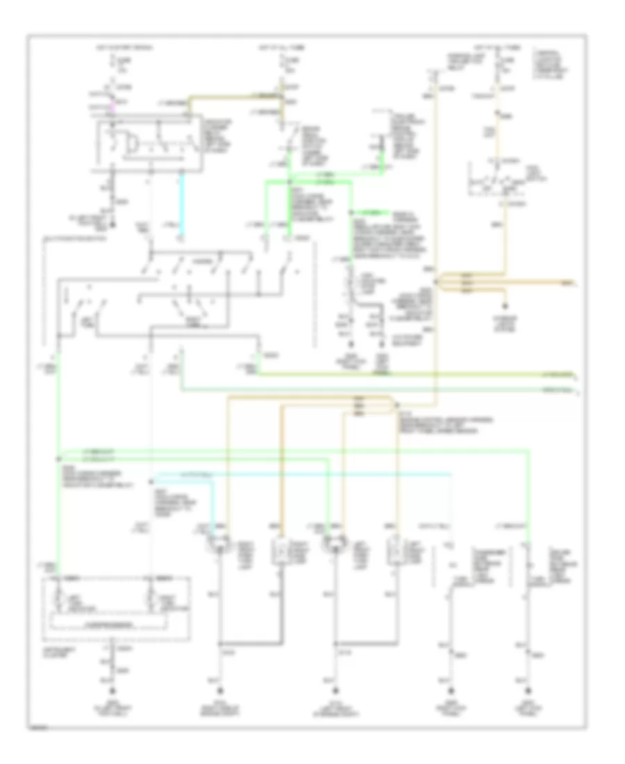
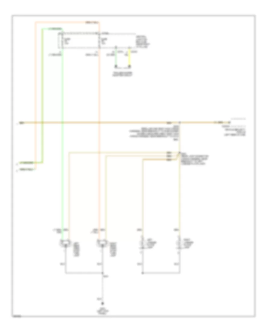
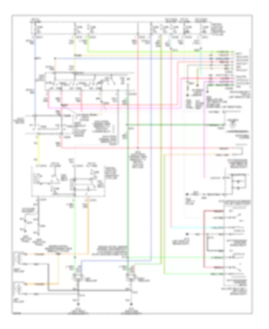
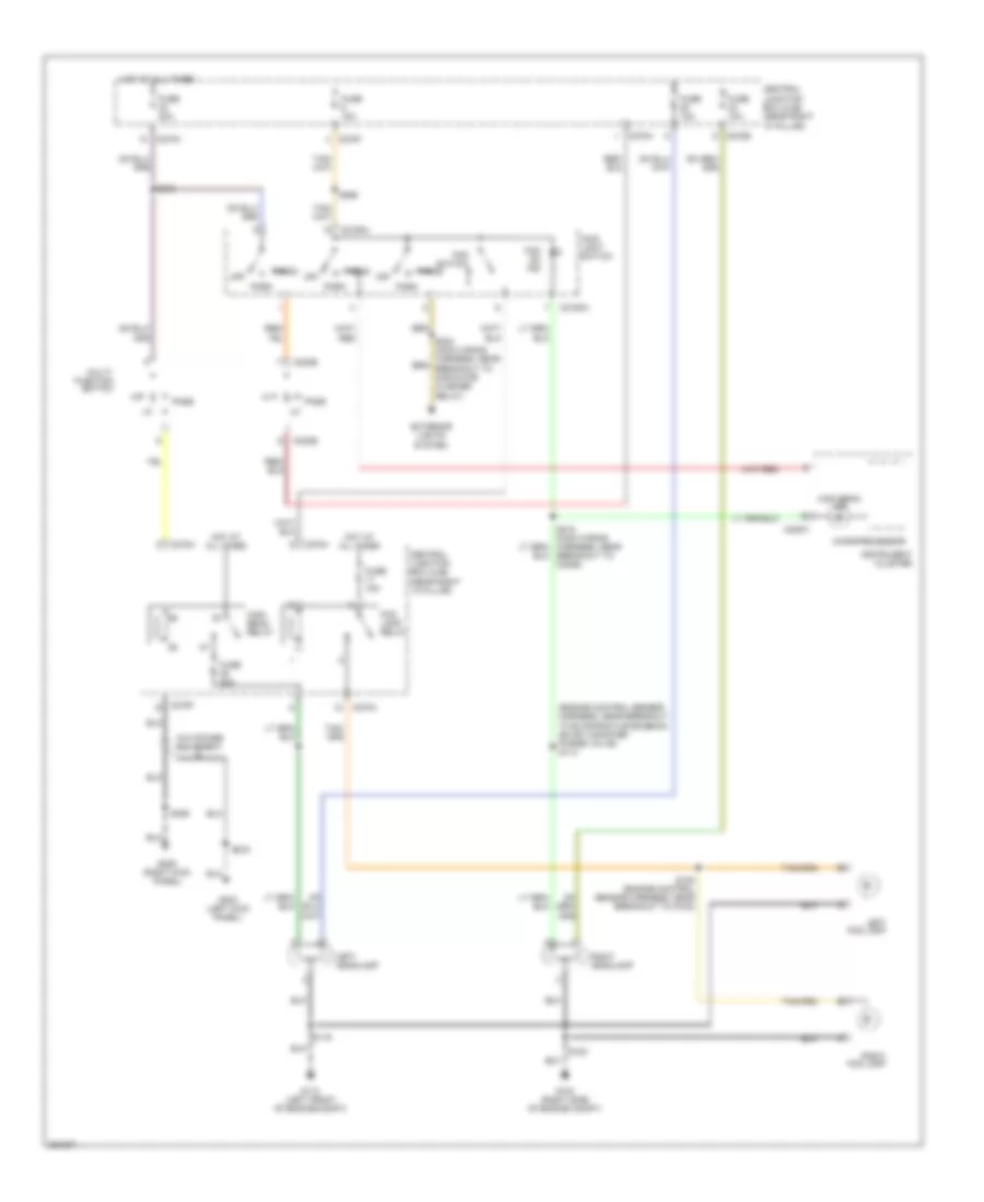
Autolamps Wiring Diagram, with DRL for Ford Pickup F150 2007
List of elements for Autolamps Wiring Diagram, with DRL for Ford Pickup F150 2007:
- (engine control sensor harness, near breakout to evaporative emission (evap) canister purge valve)
- (engine control sensor harness, near breakout to g102)
- (main wiring harness, near breakout to c2026)
- (main wiring harness, near breakout to indicator flasher relay)
- (near breakout to autolamp/ sunload sensor)
- Auto
- Autolamp/sunload sensor (top left side of dash)
- Autolp_in
- Autolp_sn
- Auxiliary relay box 1 (left side of engine compt)
- Batt
- C202b
- C2150a
- C220a
- C270a
- C270b
- C270d
- C270f
- C270h
- C270j
- C270n
- C3008a
- C3008b
- Central junction box (cjb) (near right "a" pillar)
- Daytime running lamps (drl) enable relay
- Daytime running lamps (drl) relay
- Daytime running lamps resistor (left front of engine compt)
- Exterior lights system
- Fog lamp relay
- Fog on ind
- Fog switch
- Fuse 10a
- Fuse 15a
- Fuse 20a
- Fuse 30a
- G104 (right side of engine compt)
- G110 (left front of engine compt)
- G200 (left "a" pillar)
- G206 (right kick panel)
- G300 (regular cab: left rear of cab) (super cab/ super crew: left rear panel)
- G303 (left kick panel)
- Gnd
- Hdlp_out
- Hdlp_pwr
- Head
- High beam ind
- High beam relay
- Hot at all times
- Hot in run or start
- Instrument cluster
- Left fog lamp
- Left headlamp
- Main light switch
- Microprocessor
- Multi- function switch
- Off
- Park
- Pass
- Pklp_out
- Pklp_pwr
- R/s_pwr
- Right fog lamp
- Right headlamp
- S100
- S108
- S112
- S114
- S116
- S208
- S212
- S216
- S218
- S224
- S228
- S266
- S267
- S278 (main wiring harness, near breakout to central junction box (cjb))
- S355
- Solid state
- Vehicle security module (left rear of cab)
- W/o power equip- ment
- W/o power equipment
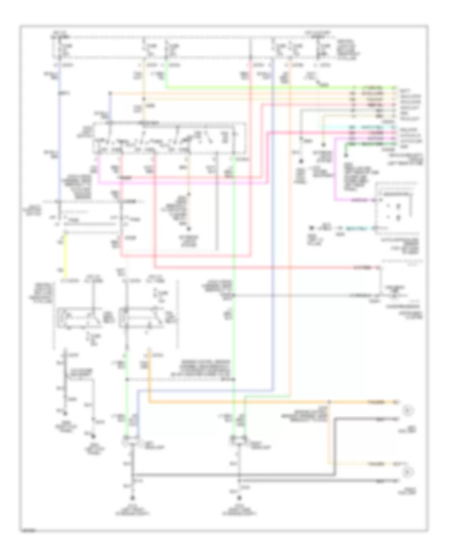
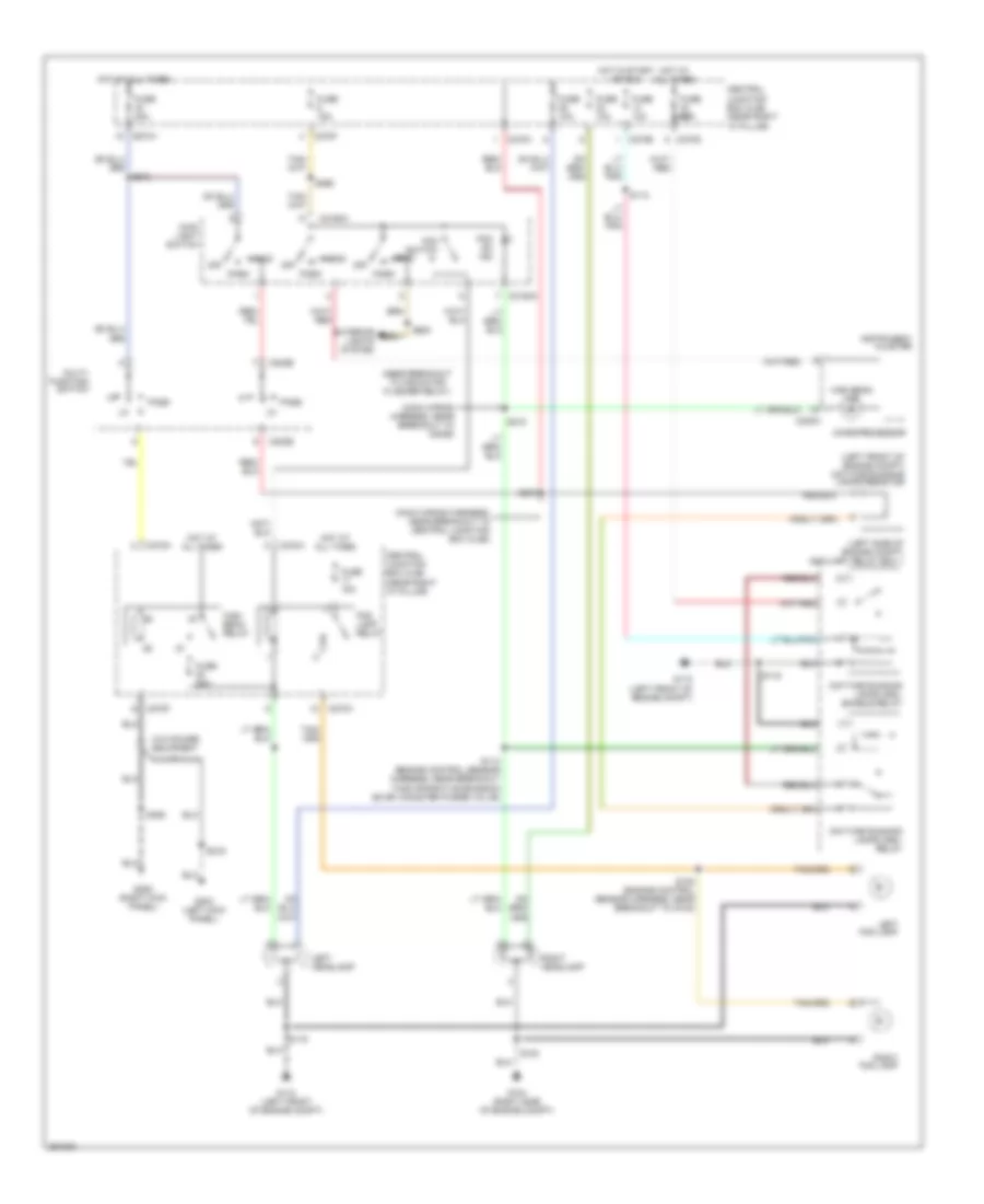
Autolamps Wiring Diagram, without DRL for Ford Pickup F150 2007
List of elements for Autolamps Wiring Diagram, without DRL for Ford Pickup F150 2007:
- (engine control sensor harness, near breakout to evaporative emission (evap) canister purge valve)
- (main wiring harness, near breakout to autolamp/ sunload sensor)
- (main wiring harness, near breakout to c2026) s218
- Auto
- Autolamp/sunload sensor (top left side of dash)
- Autolp_in
- Autolp_sn
- Batt
- C202b
- C2150a
- C220a
- C270a
- C270b
- C270f
- C270h
- C270j
- C270n
- C3008a
- C3008b
- Central junction box (cjb) (near right "a" pillar)
- Exterior lights system
- Fog lamp relay
- Fog on ind
- Fog switch
- Fuse 10a
- Fuse 15a
- Fuse 20a
- Fuse 30a
- G104 (right side of engine compt)
- G110 (left front of engine compt)
- G200 (left "a" pillar)
- G206 (right kick panel)
- G300 (regular cab: left rear of cab) (super cab/ super crew: left rear panel)
- G303 (left kick panel)
- Gnd
- Hdlp_out
- Hdlp_pwr
- Head
- High beam ind
- High beam relay
- Hot at all times
- Hot in start or run
- Instrument cluster
- Left fog lamp
- Left headlamp
- Main light switch
- Microprocessor
- Multi- function switch
- Off
- Park
- Pass
- Pklp_out
- Pklp_pwr
- R/s_pwr
- Right fog lamp
- Right headlamp
- S100
- S108 (engine control sensor harness, near breakout to g102)
- S114
- S116
- S208
- S212
- S216
- S224 (near breakout to indicator flasher relay)
- S228
- S267
- S355
- Solid state
- Vehicle security module (left rear of cab)
- W/o power equipment
Headlamps Wiring Diagram, with DRL for Ford Pickup F150 2007
List of elements for Headlamps Wiring Diagram, with DRL for Ford Pickup F150 2007:
- (left front of engine compt) daytime running lamps resistor
- (left side of engine compt) auxiliary relay box 1
- (main wiring harness, near breakout to c2026)
- (main wiring harness, near breakout to central junction box (cjb))
- (near breakout to indicator flasher relay)
- C202b
- C2150a
- C220a
- C270a
- C270b
- C270d
- C270f
- C270h
- Central junction box (cjb) (near right "a" pillar)
- Daytime running lamps (drl) enable relay
- Daytime running lamps (drl) relay
- Exterior lights system
- Fog lamp relay
- Fog on ind
- Fog switch
- Fuse 10a
- Fuse 15a
- Fuse 20a
- G104 (right side of engine compt)
- G110 (left front of engine compt)
- G206 (right kick panel)
- G303 (left kick panel)
- Head
- High beam ind
- High beam relay
- Hot at all times
- Hot in start or run
- Instrument cluster
- Left fog lamp
- Left headlamp
- Main light switch
- Microprocessor
- Multi- function switch
- Off
- Park
- Pass
- Right fog lamp
- Right headlamp
- S100
- S108 (engine control sensor harness, near breakout to g102)
- S112
- S114 (engine control sensor harness, near breakout to evaporative emission (evap) canister purge valve)
- S116
- S212
- S216
- S218
- S224
- S266
- S278
- S355
- W/o power equipment
Headlamps Wiring Diagram, without DRL for Ford Pickup F150 2007
List of elements for Headlamps Wiring Diagram, without DRL for Ford Pickup F150 2007:
- (engine control sensor harness, near breakout to evaporative emission (evap) canister purge valve) s114
- C202b
- C2150a
- C220a
- C270a
- C270b
- C270f
- C270h
- Central junction box (cjb) (near right "a" pillar)
- Exterior lights system
- Fog lamp relay
- Fog on ind
- Fog switch
- Fuse 10a
- Fuse 15a
- Fuse 20a
- G104 (right side of engine compt)
- G110 (left front of engine compt)
- G206 (right kick panel)
- G303 (left kick panel)
- Head
- High beam ind
- High beam relay
- Hot at all times
- Instrument cluster
- Left fog lamp
- Left headlamp
- Main light switch
- Microprocessor
- Multi- function switch
- Off
- Park
- Pass
- Right fog lamp
- Right headlamp
- S100
- S108 (engine control sensor harness, near breakout to g102)
- S116
- S212
- S216
- S218 (main wiring harness, near breakout to c2026)
- S266
- S355
- W/o power equipment
HORN
Horn Wiring Diagram for Ford Pickup F150 2007
List of elements for Horn Wiring Diagram for Ford Pickup F150 2007:
- (main wiring harness, near breakout to ignition switch) s296
- Audio unit
- C175b
- C218b
- C270a
- C270e
- C290a
- C3008a
- Central junction box (cjb) (near right "a" pillar)
- Clockspring (in steering column)
- Cruise control system
- Fuse 26 20a
- G104 (right side of engine compartment)
- High pitch horn
- Horn (right front of vehicle)
- Horn relay
- Horn switch (in steering wheel)
- Horn_ lsd_ out
- Hot at all times
- Low pitch horn
- Nca
- Powertrain control module (pcm) (right rear of engine compt)
- S100
- S295 (main wiring harness, near breakout to brake shift interlock solenoid)
- Sccs rtn
- Sound systems
- Swc-
- Vehicle security module (left rear of cab)
INSTRUMENT CLUSTER
Instrument Cluster Wiring Diagram for Ford Pickup F150 2007
List of elements for Instrument Cluster Wiring Diagram for Ford Pickup F150 2007:
- (in left front footwell)
- (left front of engine compt) g110
- 5.4l flex fuel
- Ac cl req
- Ac/dc convertor
- Accessory delay relay
- Air bag chime
- Air bag ind
- Air bag indicator
- Air conditioning system
- Ambient air temperature sensor (front of engine compartment)
- Batt svr rly
- Brake fluid level switch (on brake fluid reservoir)
- Bulb gnd
- C220a
- C220b
- C270e
- C270f
- C270j
- C3008b
- C310a
- Can +
- Can -
- Central junction box (cjb) (near right "a" pillar)
- Compass +
- Compass -
- Computer data lines system
- Defogger system
- Dly acc rly
- Dome defeat
- Dome switch
- Dr ajar sw in
- Driver side rear door ajar switch (in right rear door)
- Electronic compass
- Except 5.4l flex fuel
- Exterior lights system
- Fluid level switch
- Fluid level switch rtn
- Fuel level +
- Fuel level -
- Fuel pump module (on fuel tank)
- Fuse 10a
- Fuse 15a
- Fuse 5a
- G200 (left "a" pillar)
- G202
- G202 (in left front footwell)
- G206 (right kick panel)
- G303 (left kick panel)
- Gnd
- Gnd l
- Headlamp switch
- Headlights system
- Heated backlite input
- High beam
- Hot at all times
- Hot in acc or run
- Hot in start or run
- Htd bklt rly
- Illum
- Instrument cluster
- Interior lights system
- Key in
- Left front door ajar switch (in left front door)
- Left turn
- Lf ajar sw in
- Lf door ajar
- Logic gnd
- Message center switch
- Msd ctr -
- Msg ctr +
- Oat +
- Oat -
- Oil press
- Oil pressure switch (lower left front of engine)
- Optional
- Park brake switch
- Parking brake switch (on parking brake assembly)
- Passenger side rear door ajar switch (in left rear door)
- Pr ajar sw in
- Pwm dim out
- Pwm illum in
- Pwr
- Restraints control module (under driver's seat)
- Rf ajar sw in
- Rf door ajar
- Right front door ajar switch (in right front door)
- Right turn
- S110
- S205
- S208
- S225
- S242
- S265
- S277 (w/ xl, stx)
- S283
- S326
- S340
- S355
- S502
- S600
- S909
- Sw fd1
- Sw fd2
- Ubp
- Vbatt
- Vehicle security module (left rear of cab)
- Vpwr
- Warning system
INTERIOR LIGHTS
Courtesy Lamps Wiring Diagram for Ford Pickup F150 2007
List of elements for Courtesy Lamps Wiring Diagram for Ford Pickup F150 2007:
- (dome lamp connector harness, near breakout to front interior/ map lights assembly) s904
- Auto
- Battery saver relay
- Batt_ svr_ry
- C2150a
- C2150b
- C220a
- C220b
- C270e
- C270f
- C270j
- Central junction box (cjb) (near right "a" pillar)
- Chmsl
- Dome defeat
- Dome switch
- Driver side exterior rear view mirror
- Except regular cab, supercab w/o rail system
- Exterior lights system
- Front interior/map lamps assembly
- Fuse 15a
- G202 (in left front footwell)
- G206 (right kick panel)
- G303 (left kick panel)
- Gnd
- Head
- High mounted stoplamp
- Hot at all times
- Illumination circuit
- Instrument cluster
- Left vanity mirror lamp
- Lh cargo lamp
- Main light switch
- Off
- Park
- Passenger side exterior rear view mirror
- Pulse width module
- Pwm out
- Pwm_ dim_out
- Pwr
- Rear interior lamp
- Rear interior/ map lamps assembly
- Regular cab, supercab w/o rail system
- Rh cargo lamp
- Right vanity mirror lamp
- S205
- S216
- S224 (main wiring harness, near breakout to indicator flasher relay)
- S240 (body main wiring harness, in breakout to c219)
- S266
- S325 (regular cab: body main wiring harness, near breakout to subwoofer) (super cab/super crew: body main harness, near breakout to c314)
- S355
- S502
- S600
- S900 (dome lamp connector harness, near breakout to front interior/map lights assembly)
- S905
- S910
- W/ power equipment)
- W/o power equipment
Instrument Illumination Wiring Diagram for Ford Pickup F150 2007
List of elements for Instrument Illumination Wiring Diagram for Ford Pickup F150 2007:
- (main wiring harness, near breakout to indicator flasher relay) s242
- (main wiring harness, near breakout to instrument panel power point) s285
- Acc dly
- Accessory delay relay
- Adjustable pedal switch
- Audio unit
- Audio/climate control switch
- Auto
- Automatic a/c
- Auxiliary relay box 1 (left side of engine compt)
- Breakout to indicator flasher relay)
- C175b
- C2150a
- C2150b
- C218b
- C220a
- C220b
- C228a
- C270e
- C270f
- C270n
- C290a
- C294a
- C504b
- Central junction box (cjb) (near right "a" pillar)
- Circuit breaker 30a
- Clockspring (in steering column)
- Dly acc rly
- Driver side door lock switch
- Dvd player
- Electronic automatic temperature control (eatc) module (center of dash)
- Electronic manual temperature control (emtc) module (center of dash)
- Exterior lights system
- Floor shifter
- Four- wheel drive switch
- Fuse 10a
- Fuse 15a
- Fuse 5a
- G200 (left "a" pillar)
- G202 (in left front footwell)
- G206 (right kick panel)
- G303 (left kick panel)
- Gnd
- Head
- Hot at all times
- Ill+
- Illumination
- Instrument cluster
- Left rear window adjust switch
- Lock
- Main light switch
- Manual a/c
- Master window adjust switch (regular cab)
- Master window adjust switch (super cab, super crew)
- Message center switch
- Nca
- Off
- Park
- Parking aid disable switch
- Passenger side door lock switch
- Passenger side window adjust switch
- Passenger side window adjust switch (regular cab)
- Powertrain control module (pcm) (right rear of engine compt)
- Pulse width module
- Pwr out
- Rear power sliding window switch
- Right rear window adjust switch
- Roof opening panel switch
- S203
- S205
- S208
- S266
- S276 (main wiring harness, near breakout to front cigar lighter)
- S283
- S296 (main wiring harness, near breakout to ignition switch)
- S380
- S502
- S600
- S905
- Sccsrtn
- Speed control switch
- Swc-
- Traction control switch
- Vpwr
- Xlt, fx4, lariat
MEMORY SYSTEMS
Adjustable Pedal Wiring Diagram for Ford Pickup F150 2007
List of elements for Adjustable Pedal Wiring Diagram for Ford Pickup F150 2007:
- (left "a" pillar) g200
- (seat control feed jumper harness, near breakout to driver seat module)
- Adjustable pedal memory potentiometer (under left end of dash)
- Adjustable pedal motor (behind lower left side of dash)
- Adjustable pedal switch
- C270m
- C341a
- C341b
- C341c
- Central junction box (cjb) (near right ``a" pillar)
- Driver seat module (below driver's seat)
- Forward
- Fuse 30a
- Fwd (+/-)
- G200 (left "a" pillar)
- G202 (in left front footwell)
- G303 (left kick panel)
- Gnd
- Hot at all times
- Interior lights system
- Memory seat & mirrors circuit
- Rearward
- Rest
- Rwd (+/-)
- S205
- S208
- S301
- S302
- S310
- S314
- Sig
- Sig rtn
- Vbatt
- Vref
Memory Seat & Mirrors Wiring Diagram (1 of 3) for Ford Pickup F150 2007
List of elements for Memory Seat & Mirrors Wiring Diagram (1 of 3) for Ford Pickup F150 2007:
- +/-
- Adjustable pedal circuit
- Auto-dimming interior mirror mirror unit
- C270j
- C270m
- C341a
- C341b
- C341c
- C341d
- Central junction box (cjb) (near right "a" pillar)
- Computer data lines system
- Down
- Driver seat module (below driver's seat)
- Ec gnd
- Ec pwr
- Exterior rear view mirror switch
- Feed
- Fuse 10a
- Fuse 30a
- Fuse 7.5a
- Fwd (+/-)
- G200 (left "a" pillar)
- G303 (left kick panel)
- Gnd
- Hot at all times
- L/r sns
- Left
- Left fld
- Left motor
- Motor com
- Pnk
- Red
- Right
- Right fld
- Right motor
- Rwd (+/-)
- S211
- S310
- S314
- S315
- S345
- S502
- Sens sig
- Set 1 sw
- Set 2 sw
- Set sw
- Sig
- Sig rtn
- Sw sns
- U/d sns
- Ubp bus
- Vbatt
- Vref
Memory Seat & Mirrors Wiring Diagram (2 of 3) for Ford Pickup F150 2007
List of elements for Memory Seat & Mirrors Wiring Diagram (2 of 3) for Ford Pickup F150 2007:
- (left ``a" pillar) g200
- (near breakout to exterior rear view mirror switch) s500
- (near breakout to passenger safety belt tension sensor)
- Defogger system
- Driver side exterior rear view mirror
- Driver side front seat adjust switch
- Ec gnd
- Ec pwr
- Exterior lights system
- Forward/ forward/ rearward rearward
- Front up/down
- Fwd
- G303 (left kick panel)
- Heater
- Illum
- Interior lights system
- Left/right
- Nca
- Pnk
- Position sensors
- Power fold circuitry
- Power folding mirror module (left "c" pillar)
- Rear up/down
- Red
- Rwd
- S207 (near breakout for passenger safety belt tension sensor)
- S214
- S217
- S340
- S502
- Turn signal
- Up dn dn
- Up/down
Memory Seat & Mirrors Wiring Diagram (3 of 3) for Ford Pickup F150 2007
List of elements for Memory Seat & Mirrors Wiring Diagram (3 of 3) for Ford Pickup F150 2007:
- (below driver's seat) driver memory seat front height sensor
- (below driver's seat) driver memory seat horizontal sensor
- (left ``a" pillar) g200
- (seat control feed jumper harness, near breakout to driver seat module)
- Adjustable pedal memory potentiometer (under left end of dash)
- Defogger system
- Driver memory seat rear height sensor (below driver's seat)
- Exterior lights system
- G206 (right kick panel)
- Heater
- Illum
- Interior lights system
- Left power seat motor assembly (below driver's seat)
- Left/right
- Memory set switch
- Passenger side exterior rear view mirror
- Pnk
- Position sensors
- Power fold circuitry
- S301
- S302
- S600
- Seat forward/ rearward
- Seat up/down front
- Seat up/down rear
- Set
- Set 1
- Set 2
- Turn signal
- Up/down
NAVIGATION
Parking Assistant Wiring Diagram for Ford Pickup F150 2007
List of elements for Parking Assistant Wiring Diagram for Ford Pickup F150 2007:
- (backup alarm jumper harness, in breakout to c410) s4000
- (backup alarm jumper harness, in breakout to c410) s4001
- (left "a" pillar) g200
- C270j
- Central junction box (cjb) (near right "a" pillar)
- Computer data lines system
- Exterior lights system
- Fuse 18 10a
- G202 (in left front footwell)
- Gnd
- Hot in start or run
- Illumination
- Interior lights system
- Iso
- Left inner parking aid sensor (regular cab: on rear bumper) (super cab/crew cab: left side of rear bumper)
- Left outer parking aid sensor (on rear bumper)
- Li sensor in
- Lo sensor in
- On/off switch
- Pam ind
- Parking aid disable switch
- Parking aid module (pam) (under left end of dash)
- Parking aid speaker (left kick panel)
- Pwr run
- Rear sounder (+)
- Rear sounder (-)
- Reverse in
- Ri sensor in
- Right inner parking aid sensor (on rear bumper)
- Right outer parking aid sensor (regular cab: on rear bumper) (super cab/crew cab: right rear corner of vehicle)
- Ro sensor in
- S203
- S228
- S326
- Sensor gnd
- Sensor pwr
- Solid state
- Status led
POWER DISTRIBUTION
Power Distribution Wiring Diagram (1 of 3) for Ford Pickup F150 2007
List of elements for Power Distribution Wiring Diagram (1 of 3) for Ford Pickup F150 2007:
- (body main wiring harness, in breakout for central junction box (cjb)
- (diagram 1 of 3)
- (engine control sensor harness, near breakout to g102) (late prod: engine control sensor harness, near breakout to integrated wheel ends solenoid)
- (engine control sensor harness, near rt rear of eng compt) s236
- (main wiring harness, near breakout to autolamp/ sunload sensor) (w/ body security module) s266
- (seat control feed jumper harness, near breakout to driver seat module) s315
- (w/ 4x4) s105
- (w/ memory)
- A/c clutch relay
- Abs control module
- Audio unit
- Auto a/c
- Autolamp/ sunload sensor
- Auxiliary relay box 1 (left side of engine compt)
- Battery
- Battery saver relay
- Brake pedal position switch
- C102a
- C102b
- C175b
- C205a
- C228a
- C270b
- C270c
- C270d
- C270e
- C270f
- C270g
- C270h
- C270j
- C270m
- C270n
- C270p
- C290a
- C294a
- C3008a
- C341c
- Center console) s338
- Central junction box (cjb) (near right ``a" pillar)
- Console 1 power point
- Console 2 power point
- Data link connector (dlc)
- Driver seat module
- Driver side front seat adjust switch
- Dvd player
- Electronic automatic temperature control (eatc) module
- Electronic manual temperature control (emtc) module
- Evap canister vent control solenoid
- Exterior rear view mirror switch
- From fuse 5 a
- Front blower motor relay
- Front cigar lighter
- Fuse 10a
- Fuse 15a
- Fuse 20a
- Fuse 25a
- Fuse 30a
- Fuse 40a
- Fuse 41 (early prod) 110 (late prod) 20a
- Fuse 7.5a
- G202 (in left front footwell)
- G206 (right kick panel)
- Generator
- Horn relay
- Indicator flasher relay
- Instrument panel power point
- Integrated wheel ends solenoid (w/ 4x4)
- Main light switch
- Main wiring harness
- Manual a/c
- Nca
- Passenger side front seat adjust switch
- Power folding mirror relay
- Powertrain control module (pcm)
- Red
- Red/ s211
- S113
- S120 (alternator rectifier harness, near breakout to fusible link a, b or c)
- S201
- S203
- S209
- S345 (w/ memory) (body main harness near right rear door switch)
- S355
- S380
- Satellite audio receiver
- Starter motor
- Starter relay
- Subwoofer
- To fuse 109 (diagram 2 of 3)
- To fuse 6 (diagram 1 of 3)
- Trailer electronic brake control module
- Trailer tow battery charge relay
- Trailer tow parking lamp relay
- Trailer tow reversing lamp relay
- Vehicle security module
- W/ satellite
Power Distribution Wiring Diagram (2 of 3) for Ford Pickup F150 2007
List of elements for Power Distribution Wiring Diagram (2 of 3) for Ford Pickup F150 2007:
- (body main harness, below driver's seat)
- (diagram 1 of 3)
- (engine control sensor harness, in breakout to auxiliary box 1) s111
- (engine control sensor harness, right rear of engine compt)
- (main wiring harness, in breakout to electronic manual temperature control (emtc) module)
- (near right "a" pillar) central junction box (cjb)
- (near right ``a" pillar) central junction box (cjb)
- (not used)
- A/c clutch cycling pressure switch
- Abs control module
- Acc
- Adjustable pedal switch (w/o memory)
- Audio unit
- Auto a/c
- Auxiliary power point
- Auxiliary relay box 1 (left side of engine compartment)
- Brake pedal position switch
- Brake shift interlock
- Breakout to brake shift interlock solenoid)
- C220a
- C220b
- C270b
- C270c
- C270d
- C270e
- C270f
- C270g
- C270h
- C270k
- C270m
- C290a
- C341b
- Clockwise (cw) motor 4x4 relay
- Counterclockwise (ccw) motor 4x4 relay
- Daytime running lamps (drl) enable relay
- Deactivator switch
- Digital transmission range (dtr) sensor
- Driver seat module
- Driver side front heated seat module
- Driver side front seat adjust switch
- Electronic automatic temperature control (eatc) module
- Electronic manual temperature control (emtc) module
- Floor shifter
- From fuse 10 b
- Front blower motor relay
- Fuse 10a
- Fuse 20a
- Fuse 30a
- Fuse 40a
- Fuse 5a
- G303 (left kick panel)
- Heated positive crankcase ventilation (pcv) valve (5.4l)
- Heated rear window relay
- Ignition switch
- Indicator flasher relay
- Instrument cluster
- Key in ignition switch
- Key removal inhibit solenoid
- Manual a/c
- Nca
- Off/ lock
- Passenger air bag deactivation (pad) indicator
- Passenger side front heated seat module
- Pcm power relay
- Red
- Reversing lamps switch (m/t)
- Run
- S112
- S210
- S320
- S905
- Start
- Tan/ red
- To fuse (diagram 3 of 3)
- To fuse 18 (diagram 3 of 3)
- To fuse 21 (diagram 3 of 3)
- Trailer tow battery charge relay
- W/ memory
- W/o memory
- Windshield wiper motor
- Xlt, fx4, lariat
Power Distribution Wiring Diagram (3 of 3) for Ford Pickup F150 2007
List of elements for Power Distribution Wiring Diagram (3 of 3) for Ford Pickup F150 2007:
- (body main harness, near breakout to restraints control module) s323
- (body main wiring harness, in right rear door) s344
- (body main wiring harness, near breakout to central junction box (cjb)) s228
- (diagram 2 of 3)
- (interior lamp harness, near breakout to electronic compass)
- (main wiring harness, behind dash panel) s225
- (main wiring harness, near breakout to instrument panel power point) s285
- (near right "a" pillar) central junction box (cjb)
- 4.2l
- Accessory delay relay
- Audio unit (xlt, fx4, lariat)
- Auto-dimmer interior mirror unit
- Auxiliary relay box 1 (left side of engine compt)
- C175b
- C202b
- C205a
- C220b
- C270b
- C270d
- C270e
- C270f
- C270h
- C270j
- C270m
- C270n
- C290a
- C3008a
- C3008b
- C310a
- C504b
- Central junction box (cjb) (near right "a" pillar)
- Circuit breaker 30a
- Daytime running lamps (drl) enable relay
- Driver side door lock switch
- Driver side front heated seat module
- Electronic compass
- Floor shifter
- Fog lamp relay
- From auxiliary power point (diagram 2 of 3)
- From c fuse 102 (diagram 2 of 3)
- From fuse 27 d
- Fuel pump diode
- Fuel pump relay
- Fuse 10a
- Fuse 15a
- Fuse 20a
- Fuse 5a
- High beam relay
- Instrument cluster
- Main light switch
- Master window adjust switch
- Master window adjust switch (regular cab)
- Multi- function switch
- Overdrive cancel switch
- Parking aid module (pam)
- Passenger side door lock switch
- Passenger side front heated seat module
- Passenger side window adjust switch (regular cab)
- Passive anti-theft transceiver module
- Powertrain control module
- Rear power sliding window switch
- Restraints control module
- Roof opening panel module
- Roof opening panel module (lt only)
- Roof opening panel switch
- S909
- Seat weight sensor module
- Traction control switch
- Vehicle security module
POWER DOOR LOCKS
Power Door Locks Wiring Diagram for Ford Pickup F150 2007
List of elements for Power Door Locks Wiring Diagram for Ford Pickup F150 2007:
- (body main wiring harness, near breakout to c339) s342
- (in right rear door) (w/ super crew) passenger side rear door ajar switch
- (left kick panel) g303
- (regular cab: body main wiring harness, near breakout to subwoofer) (super cab/super crew: body main wiring harness, near breakout to c339)
- (regular cab: left rear of cab) (super cab/super crew: left rear panel) g300
- (right kick panel) g206
- (w/o power equipment) s216
- 1/2
- 3/4
- 5/6
- 7/8
- 9/0
- Air conditioning system
- All lock rly out
- Autolp sn
- Autolp sw in
- Batt
- C270f
- C270h
- C270j
- C270n
- C3008a
- C3008b
- Central junction box (cjb) (near right "a" pillar)
- Computer data lines system
- Df ajar sw in
- Df unlock rly out
- Dr ajar sw in
- Driver side door lock switch
- Driver side rear door ajar switch (w/ super crew) (in left rear door)
- Exterior lights system
- Fuse 10a
- Fuse 15a
- Fuse 20a
- Fuse 30a
- G303 (left kick panel)
- Hdlp pwr
- Hdlp rly out
- Headlights system
- Horn rly ctrl
- Horns system
- Hot at all times
- Hot in run or start
- Illumination
- Interior lights system
- Keypad a sw in
- Keypad b sw in
- Keypad c sw in
- Keypad ill gnd
- Keypad ill out
- Keypad keyless entry
- Left front door ajar switch (in left front door)
- Left front door lock actuator (in left front door)
- Left rear door lock actuator (in left rear door)
- Lock
- Lock sw in
- Passenger side door lock switch
- Pf ajar sw in
- Pklp pwr
- Pklp rly out
- Pr ajar sw in
- Pwr gnd
- R/s pwr
- Red
- Right front door ajar switch (in right front door)
- Right front door lock actuator (in right front door)
- Right rear door lock actuator (in right rear door)
- S212
- S228
- S266
- S339
- S340
- S341 (body main wiring harness, near breakout to c339)
- S343
- S355
- S502
- S600
- Sig gnd
- Ubp bus
- Unlock
- Unlock rly out
- Unlock sw in
- Vehicle security module (left rear of cab)
- W/ super crew
POWER MIRRORS
Electronic Day/Night Mirror Wiring Diagram for Ford Pickup F150 2007
List of elements for Electronic Day/Night Mirror Wiring Diagram for Ford Pickup F150 2007:
- (w/o vanity mirrors) s355
- Auto-dimming interior mirror unit
- C270b
- C270j
- Central junction box (cjb) (near right "a" pillar)
- Digital transmission range (dtr) sensor (on left side of transmission)
- Driver side exterior rear view mirror
- Ec gnd
- Ec pwr
- Exterior lights system
- Fuse 10a
- G206 (right kick panel)
- Ground
- Hot in start or run
- Power
- Reverse
- S112
- S290 (in breakout to central junction box (cjb))
- S297 (in breakout to central junction box (cjb))
- S909
- S910 (w/ vanity mirrors)
Power Mirrors Wiring Diagram for Ford Pickup F150 2007
List of elements for Power Mirrors Wiring Diagram for Ford Pickup F150 2007:
- (if equipped) (in breakout to passenger side exterior rear view mirror)
- (if equipped) s503
- (left "c" pillar) (w/ power folding mirrors) power folding mirror module
- (near breakout to driver side exterior rear view mirror)
- C270j
- Central junction box (cjb) (near right "a" pillar)
- Defogger system
- Down
- Driver side exterior rear view mirror
- Ec gnd
- Ec pwr
- Electronic day/night mirror circuit
- Exterior lights system
- Exterior rear view mirror switch
- Fuse 10a
- Fuse 7.5a
- G206 (right kick panel)
- G303 (left kick panel)
- Heater
- Hot at all times
- Illum
- Interior lights system
- Left
- Left fld
- Left motor
- Left/right
- Passenger side exterior rear view mirror
- Power fold circuitry
- Red
- Right
- Right fld
- Right motor
- S207 (near breakout for passenger safety belt tension sensor)
- S211
- S340
- S345
- S500 (near breakout to exterior rear view mirror switch)
- S502
- S600
- S603 s501 (near breakout to exterior rear view mirror switch)
- Signal
- Turn
- Turn signal
- Up/down
POWER SEATS
Adjustable Pedal Wiring Diagram for Ford Pickup F150 2007
List of elements for Adjustable Pedal Wiring Diagram for Ford Pickup F150 2007:
- Adjustable pedal motor (behind lower left side of dash)
- Adjustable pedal switch
- Back
- C270h
- Central junction box (cjb) (near right ``a" pillar)
- Front
- Fuse 30a
- G200 (left ``a" pillar)
- G202 (in left front footwell)
- Hot at all times
- Interior lights system
- Red
- S205
- S208
Driver Power Seat Wiring Diagram for Ford Pickup F150 2007
List of elements for Driver Power Seat Wiring Diagram for Ford Pickup F150 2007:
- C270m
- Central junction box (cjb) (near right ``a" pillar)
- Driver side front seat adjust switch
- Forward/ rearward
- Front up/down
- Fuse 109 30a
- Fwd
- G200 (left "a" pillar)
- G303 (left kick panel)
- Hot at all times
- Left power seat motor assembly (below driver's seat)
- Nca
- Rear up/down
- Rwd
- S314
- S340
- Seat forward/rearward
- Seat up/down front
- Seat up/down rear
- Up/down
- W/ memory seats
- W/o memory seats
Heated Seats Wiring Diagram for Ford Pickup F150 2007
List of elements for Heated Seats Wiring Diagram for Ford Pickup F150 2007:
- (w/ memory seats) s310
- C228b
- C270j
- C270m
- Central junction box (cjb) (near right ``a" pillar)
- Driver side front heated seat module (below driver's seat)
- Electronic automatic temperature control (eatc) module (center of dash)
- Fuse 10a
- Fuse 30a
- G206 (right kick panel)
- G303 (left kick panel)
- Hot at all times
- Hot in start or run
- Left front seat back heater (in driver's seat back)
- Left front seat cushion heater (in driver's seat cushion)
- Nca
- Passenger side front heated seat module (below right front seat)
- Red
- Right front seat back heater (in right front seat back)
- Right front seat cushion heater (below right front seat)
- S228
- S308
- S320
Passenger Power Seat Wiring Diagram for Ford Pickup F150 2007
List of elements for Passenger Power Seat Wiring Diagram for Ford Pickup F150 2007:
- C270m
- Central junction box (cjb) (near right ``a" pillar)
- Forward/ rearward
- Front up/down
- Fuse 30a
- G206 (right kick panel)
- Hot at all times
- Nca
- Passenger side front seat adjust switch
- Rear up/down
- Right power seat motor assembly (below passenger's seat)
- Rwd fwd
- S308 s308
- Seat forward/rearward
- Seat up/down front
- Seat up/down rear
- Up/down
POWER TOP/SUNROOF
Power Top/Sunroof Wiring Diagram for Ford Pickup F150 2007
List of elements for Power Top/Sunroof Wiring Diagram for Ford Pickup F150 2007:
- (right kick panel) g206
- Accessory delay relay
- C220b
- C270e
- C270n
- Central junction box (cjb) (near right "a" pillar)
- Circuit breaker 401 30a
- Close
- Close tilt up
- Del/acc
- Fuse 10a
- G303 (left kick panel)
- Gnd
- Gnd user sw common
- Hot at all times
- Illumination
- Instrument cluster
- Open
- Open tilt down
- Roof opening panel module (in roof panel)
- Roof opening panel switch
- S331
- S344
- S355
- S905
- Tan/red
POWER WINDOWS
Power Windows Wiring Diagram, Crew Cab & Super Cab for Ford Pickup F150 2007
List of elements for Power Windows Wiring Diagram, Crew Cab & Super Cab for Ford Pickup F150 2007:
- (near breakout to c339) s337
- Acc delay relay ctrl c220b
- Accessory delay relay
- Atsw
- C270e
- C270n
- C504a
- C504b
- Central junction box (cjb) (near right "a" pillar)
- Close
- Driver
- Driver side front power window motor (in left front door)
- Fuse 30a
- G303 (left kick panel)
- Hot at all times
- Illum
- Instrument cluster
- Left rear
- Left rear door power window motor (in left rear door)
- Left rear window adjust switch
- Lock
- Master window adjust switch
- One- touch down
- One-touch down relay
- Open
- Passenger
- Passenger side front power window motor (in right front door)
- Passenger side window adjust switch
- Rear power sliding window motor (behind rear seats)
- Rear power sliding window switch
- Rest
- Right rear
- Right rear door power window motor (in right rear door)
- Right rear window adjust switch
- Rsin
- S344
- S502
- S905
- Vcc
- Vpwr
- Vth
Power Windows Wiring Diagram, Regular Cab for Ford Pickup F150 2007
List of elements for Power Windows Wiring Diagram, Regular Cab for Ford Pickup F150 2007:
- Acc delay relay ctrl c220b
- Accessory delay relay
- C270e
- C270n
- Central junction box (cjb) (near right "a" pillar)
- Close
- Down
- Driver
- Driver side front power window motor (in left front door)
- Fuse 30a
- G303 (left kick panel)
- Hot at all times
- Illum
- Instrument cluster
- Master window adjust switch
- Open
- Passenger
- Passenger side front power window motor (in right front door)
- Passenger side window adjust switch
- Rear power sliding window motor (behind rear seats)
- Rear power sliding window switch
- S344
- S502
- S905
RADIO
Radio Wiring Diagram, with DVD (1 of 2) for Ford Pickup F150 2007
List of elements for Radio Wiring Diagram, with DVD (1 of 2) for Ford Pickup F150 2007:
- (in left front footwell)
- (or 54)
- Audio input jack
- Audio unit
- C270e
- C270f
- C270m
- C290a
- C290b
- C290c
- Cddjl (+)
- Cddjl (-)
- Cddjr (+)
- Cddjr (-)
- Central junction box (cjb) (near right "a" pillar)
- Enable
- Engine controls system
- Fuse 10a
- Fuse 25a
- Fuse 5a
- Fuse ign
- G201 (behind dash panel)
- G202
- G301 (super cab/super crew: left rear panel) (regular cab: left rear of cab)
- Ground
- Hot at all times
- Hot in run or acc
- Hot in start
- Hot w/ acc delay relay energized
- Illum (+)
- Illumination
- Interior lights system
- Left front speaker
- Left rear speaker
- Lf spkr (+)
- Lf spkr (-)
- Lr spkr (+)
- Lr spkr (-)
- Ms can (+)
- Ms can (-)
- Nca
- Pnk
- Power
- Red
- Reverse in
- Rf spkr (+)
- Rf spkr (-)
- Right front speaker
- Right rear speaker
- Rr spkr (+)
- Rr spkr (-)
- S277
- S283
- S285
- Shield
- Signal
- Signal return
- Subwoofer
- Subwoofer(+)
- Subwoofer(-)
- Tan
- Vss
- Xl & stx
- Xlt, fx4 & lariat
Radio Wiring Diagram, with DVD (2 of 2) for Ford Pickup F150 2007
List of elements for Radio Wiring Diagram, with DVD (2 of 2) for Ford Pickup F150 2007:
- (main wiring harness, near breakout to satellite audio receiver)
- Air conditioning system
- Audio shld
- Audio/ climate control switch
- Batt
- C175b
- C218b
- C270h
- C270j
- Central junction box (cjb) (near right "a" pillar)
- Clockspring (in steering column)
- Cruise control system
- Drain wire
- Dvd player
- Fan +
- Fan -
- Fuse 10a
- Fuse 20a
- G201 (behind dash panel)
- G301 (super cab/super crew: left rear panel) (regular cab: left rear of cab)
- G303 (left kick panel)
- Ground
- Horns system
- Hot at all times
- Illum
- Illum +
- Illum -
- Interior lights system
- Left sig +
- Left sig -
- Lr spkr (+)
- Lr spkr (-)
- Media
- Ms can +
- Ms can -
- Ms can(+)
- Ms can(-)
- Nca
- Next
- Powertrain control module (pcm) (right rear of engine compartment)
- Right sig +
- Right sig -
- Rr spkr (+)
- Rr spkr (-)
- S209
- S211
- S213
- S219
- S221
- S296 (near breakout to ignition switch)
- S905
- Satellite antenna
- Satellite audio receiver
- Sdars in l+
- Sdars in l-
- Sdars in r+
- Sdars in r-
- Sdars l(+)
- Sdars l(-)
- Sdars r(+)
- Sdars r(-)
- Sig rtn
- Tan
- Temp +
- Temp -
- Vol +
- Vol -
Radio Wiring Diagram, without DVD (1 of 2) for Ford Pickup F150 2007
List of elements for Radio Wiring Diagram, without DVD (1 of 2) for Ford Pickup F150 2007:
- (in left front footwell)
- (or 54)
- Audio input jack
- Audio unit
- C270e
- C270f
- C270m
- C290a
- C290b
- C290c
- Cddjl (+)
- Cddjl (-)
- Cddjr (+)
- Cddjr (-)
- Central junction box (bjb) (near right "a" pillar)
- Enable
- Engine controls system
- Exterior lights system
- Fuse 10a
- Fuse 25a
- Fuse 5a
- Fuse ign
- G201 (behind dash panel)
- G202
- G301 (super cab/super crew: left rear panel) (regular cab: left rear of cab)
- Ground
- Hot at all times
- Hot in run or acc
- Hot in start
- Hot w/ acc delay relay energized
- Illum (+)
- Illumination
- Interior lights system
- Left front speaker
- Left rear speaker
- Lf spkr (+)
- Lf spkr (-)
- Lr spkr (+)
- Lr spkr (-)
- Ms can(+)
- Ms can(-)
- Nca
- Pnk
- Power
- Red
- Reverse in
- Rf spkr (+)
- Rf spkr (-)
- Right front speaker
- Right rear speaker
- Rr spkr (+)
- Rr spkr (-)
- S277
- S283
- S285
- Shield
- Signal
- Signal return
- Subwoofer
- Subwoofer(+)
- Subwoofer(-)
- Tan
- Vss
- Xl & stx
- Xlt, fx4 & lariat
Radio Wiring Diagram, without DVD (2 of 2) for Ford Pickup F150 2007
List of elements for Radio Wiring Diagram, without DVD (2 of 2) for Ford Pickup F150 2007:
- (main wiring harness, near breakout to ignition switch) s296
- (main wiring harness, near breakout to satellite audio receiver)
- Air conditioning system
- Audio shld
- Audio/ climate control switch
- Batt
- C175b
- C218b
- C270h
- Central junction box (bjb) (near right "a" pillar)
- Clockspring (in steering column)
- Cruise control system
- Fan +
- Fan -
- Fuse 20a
- G201 (behind dash panel)
- Ground
- Horns system
- Hot at all times
- Illum
- Interior lights system
- Media
- Ms can(+)
- Ms can(-)
- Nca
- Next
- Powertrain control module (pcm) (right rear of engine compartment)
- S209
- S213
- Satellite antenna
- Satellite audio receiver
- Sdars l(+)
- Sdars l(-)
- Sdars r(+)
- Sdars r(-)
- Sig rtn
- Tan
- Temp +
- Temp -
- Vol +
- Vol -
SHIFT INTERLOCK
Shift Interlock Wiring Diagram, with Column Shift for Ford Pickup F150 2007
List of elements for Shift Interlock Wiring Diagram, with Column Shift for Ford Pickup F150 2007:
- (in left front footwell) g202
- (main wiring harness, (near breakout to c2026) s282
- Acc
- Brake pedal position switch (under left side of dash)
- Brake shift interlock (on steering column)
- C270b
- C270g
- Central junction box (cjb) (near right "a" pillar)
- Fuse 10a
- Fuse 20a
- Hot at all times
- Ignition switch
- Key in ignition
- Key removal inhibit solenoid
- Not used
- Off
- Park neutral position (pnp) switch
- Run
- S205
- S299 (main wiring harness, near breakout to brake shift interlock solenoid)
- Shift lock solenoid
- Start
- Tan/ red
- Xlt, fx4, lariat
Shift Interlock Wiring Diagram, with Floor Shift for Ford Pickup F150 2007
List of elements for Shift Interlock Wiring Diagram, with Floor Shift for Ford Pickup F150 2007:
- (in left front footwell) g202
- (not used)
- Acc
- Brake pedal boo
- Brake pedal position switch (under left side of dash)
- C270b
- C270f
- C270g
- Central junction box (cjb) (near right "a" pillar)
- Floor shifter
- Fuse 10a
- Fuse 20a
- Fuse 5a
- Gnd
- Hot at all times
- Ignition switch
- Illum
- Interior lights system transmissions system
- Key in
- Key removal inhibit solenoid
- O/d cancel
- Off
- Run
- Run/st
- S225
- S299 (main wiring harness, near breakout to brake shift interlock solenoid)
- S380
- Start
- Tan/ red
STARTING/CHARGING
Charging Wiring Diagram for Ford Pickup F150 2007
List of elements for Charging Wiring Diagram for Ford Pickup F150 2007:
- Battery
- C102a
- C175b
- C220a
- C220b
- C270f
- Can bus+
- Can bus-
- Central junction box (cjb) (near right 'a' pillar)
- Charge ind
- Computer data lines system
- Fuse 5a
- G100 (right rear of engine)
- G101 (right rear of engine compartment)
- G105 (right front of engine compt)
- Gen com
- Gen mon
- Generator
- Hot in run or start
- Instrument cluster
- Powertrain control module (pcm) (right rear of engine compt)
- Red
- S119
- S120
- S121
- S225
- Starting circuit
- Vpwr
Starting Wiring Diagram for Ford Pickup F150 2007
List of elements for Starting Wiring Diagram for Ford Pickup F150 2007:
- (near right "a" pillar) central junction box (cjb)
- A/t
- Acc
- Battery
- C175b
- C270a
- C270d
- C270g
- C270h
- C270p
- Digital transmission range (dtr) sensor (on left side of transmission)
- Fuse 20a
- Fuse 30a
- G100 (right rear of engine)
- G101 (right rear of engine compt)
- G105 (right front of engine compt)
- Ignition switch
- M/t
- Off
- Powertrain control module (pcm) (right rear of engine compartment)
- Red
- Run
- Start
- Starter motor
- Starter relay
- Tan/ red
SUPPLEMENTAL RESTRAINTS
Supplemental Restraints Wiring Diagram for Ford Pickup F150 2007
List of elements for Supplemental Restraints Wiring Diagram for Ford Pickup F150 2007:
- (body main harness, near breakout to restraints control module) s323
- (in steering column) clock spring
- (regular cab: body main harness, near breakout to c339) (super cab/super crew: body main harness, near breakout to restraints control module)
- (regular cab: near breakout to c339) (super cab/super crew: near breakout to restraints control module)
- (under center console) g302
- Abs warning lamp
- Airbag
- Airbag chime
- Buckle sn
- C175b
- C218a
- C220a
- C256a
- C256b
- C270e
- C270j
- C310a
- C310b
- Central junction box (cjb) (near right ``a" pillar)
- Computer data lines system
- Driver air bag (center of steering wheel)
- Driver safety belt buckle pretensioner (below driver's seat)
- Driver safety belt buckle switch (in driver's seat belt buckle)
- Driver seat position sensor (below driver's seat)
- Feed
- Front impact severity sensor (front of engine compt)
- Fuse 10a
- Fuse 5a
- G302 (under center console)
- Gnd
- Hot in start or run
- Indicator
- Instrument cluster
- Iso
- Nca
- Nca stage 1
- Nca stage 2
- Pass ind ctrl
- Passenger air bag deactivation (pad) indicator
- Passenger air bag module (behind right side of dash)
- Passenger safety belt buckle pretensioner (below right front seat)
- Passenger safety belt buckle switch (below right front seat)
- Passenger safety belt tension sensor (below right front seat)
- Powertrain control module (pcm) (right rear of engine compartment)
- Rcm can +
- Rcm can -
- Rdi
- Restraints control module (under center of front seat assembly)
- S265 (main wiring harness, under dash, near breakout to instrument panel power point)
- S300 (near breakout to right power seat motor assembly)
- S309 (near breakout to driver memory seat front height sensor)
- S324
- Seat pressure sensor (below right front seat)
- Seat weight sensor module (below right front seat)
- Shorting bar
- Sig
- Sig feed
- Sig rtn
- Solid state
- Stage
- Tan/red
- Vpwr
TRANSMISSION
4WD Wiring Diagram, Electronic for Ford Pickup F150 2007
List of elements for 4WD Wiring Diagram, Electronic for Ford Pickup F150 2007:
- (late production: engine control sensor harness, near breakout to left front wheel speed sensor)
- (main wiring harness, near breakout to c2026)
- 2wd high
- 4wd high
- 4wd low
- 4wdc
- 4wdcrtn
- 4wdiwe
- 4wdmccw
- 4wdmcs
- 4wdmcw
- 4wdp1
- 4wdp2
- 4wdp3
- 4wdp4
- 4wdprtn
- 4wdswref
- 87a
- Auxiliary relay box 1 (left side of engine compt)
- C175b
- C175t
- C220a
- C270b
- C270c
- Can +
- Can -
- Central junction box (cjb) (near right "a" pillar)
- Clockwise motor 4 x 4 relay
- Computer data lines system
- Counterclockwise motor 4 x 4 relay
- Encoder
- Four-wheel drive switch
- Fuse 10a
- Fuse 30a
- G110 (left front of engine compt)
- G202 (in left front footwell)
- Hot at all times
- Instrument cluster
- Integrated wheel ends solenoid (right rear of engine compt)
- Interior lights system
- Powertrain control module (pcm) (right rear of engine compt)
- Red
- S105 (late production: engine control sensor harness, near breakout to integrated wheel ends solenoid)
- S110 (late production: at breakout to auxiliary relay box 1)
- S111 (engine control sensor harness, in breakout to auxiliary box 1)
- S117
- S118
- S283 (near breakout to four wheel drive switch)
- S287
- S288
- Shift motor
- Transfer case assembly
4WD Wiring Diagram, Mechanical for Ford Pickup F150 2007
List of elements for 4WD Wiring Diagram, Mechanical for Ford Pickup F150 2007:
- (late production: engine control sensor harness, near breakout to left front wheel speed sensor)
- (main wiring harness, near breakout to c2026)
- (near right "a" pillar)
- 2wd high
- 4wd high
- 4wd low
- 4wdc
- 4wdcrtn
- 4wdiwe
- 4wdmcs
- 4wdmp1
- 4wdmp2
- 4wdswrtn
- 4x4 high/low indicator switch 0) low 1) high 2) 4x2 (front of transfer case)
- C175b
- C175t
- C220a
- C270b
- Can +
- Can -
- Central junction box (cjb)
- Computer data lines system
- Engine controls system
- Four-wheel drive switch
- Fuse 10a
- G202 (in left front footwell)
- Hot at all times
- Instrument cluster
- Integrated wheel ends solenoid (right rear of engine compt)
- Interior lights system
- Powertrain control module (pcm) (right rear of engine compt)
- Red
- S105 (late production: engine control sensor harness, near breakout to integrated wheel ends solenoid)
- S117
- S118
- S141 (back-up light switch to rear lamp feed harness, near breakout to powertrain control module (pcm))
- S283 (main wiring harness, near breakout to four wheel drive switch)
- S287
- S288
- Sig rtn
- Tcss
- Transfer case assembly
- Transfer case speed sensor (rear of transfer case)
A/T Wiring Diagram for Ford Pickup F150 2007
List of elements for A/T Wiring Diagram for Ford Pickup F150 2007:
- (late production: engine control sensor harness, near breakout to left front wheel speed sensor)
- (under left side of dash)
- 4r75e transmission
- C175b
- C175t
- Can +
- Can -
- Central junction box (cjb) (near right "a" pillar)
- Data link connector
- Digital transmission range (dtr) sensor (on left side of transmission)
- Electronic pressure control solenoid
- Engine controls system
- Epcs
- Feps
- Floor shifter
- Fuse 15a
- Fuse 5a
- Hot at all times
- Hot in run or start
- Oss
- Output shaft speed (oss) sensor (left side of transmission)
- Overdrive cancel switch
- Pcm power relay
- Powertrain control module (pcm) (right rear of engine compt)
- Rly ctrl
- S117
- S118
- S141 (back-up light switch to rear lamp feed harness, near breakout to powertrain control module (pcm))
- S225 (main wiring harness, near breakout to c2026)
- S284 (main wiring harness, near breakout to c3007)
- Shift solenoid a
- Shift solenoid b
- Sig rtn
- Ssa
- Ssb
- Tccs
- Tcs
- Tft
- Torque converter clutch solenoid
- Tr1
- Tr2
- Tr3a
- Tr4
- Transmission fluid temperature sensor
- Tss
- Turbine shaft speed (tss) sensor (on left side of transmission)
- W/ xlt, fx4, lariat
WARNING SYSTEMS
Warning Systems Wiring Diagram, with Remote/Keyless Entry for Ford Pickup F150 2007
List of elements for Warning Systems Wiring Diagram, with Remote/Keyless Entry for Ford Pickup F150 2007:
- (body main wiring harness, near breakout to subwoofer) s303
- (main wiring harness, near breakout to c2026) s281
- Air bag chime
- Air bag ind
- Auto
- Brake fluid level switch (on brake fluid reservoir)
- Bulb ground
- C2150a
- C220a
- C220b
- C270e
- C270f
- C270g
- C3008b
- C310a
- C310b
- Central junction box (cjb) (near right "a" pillar)
- Computer data lines system
- Df ajar sw in
- Dr ajar sw in
- Dr buckle sn
- Driver safety belt buckle switch (in driver's seat belt buckle)
- Driver side rear door ajar switch (crew cab) (in left rear door)
- Fluid level sw
- Fluid level sw ret
- Fuse 10a
- Fuse 15a
- Fuse 20a
- Fuse 5a
- G110 (left front of engine compt)
- G200 (left "a" pillar)
- G202 (in left front footwell)
- G206 (right kick panel)
- G302 (under center console)
- G303 (left kick panel)
- Head
- Headlamp switch
- Hot at all times
- Hot in run or acc
- Hot in start or run
- Ignition switch
- Instrument cluster
- Key in
- Key in ignition switch
- Left front door ajar switch (in left front door)
- Logic gnd
- Main light switch
- Off
- Park
- Parking brake switch (on parking brake assembly)
- Passenger safety belt buckle switch (below right front seat)
- Passenger side rear door ajar switch (crew cab) (in right rear door)
- Pf ajar sw in
- Pk brake sw
- Pr ajar sw in
- Ps buckle sn
- Restraints control module (under driver's seat)
- Right front door ajar switch (in right front door)
- S110
- S205
- S208
- S225
- S265
- S266
- S277 (xl, stx)
- S300
- S309
- S324
- S340
- S355
- S502
- S600
- Ubp
- Vbatt
- Vehicle security module (left rear of cab)
- Vpwr
Warning Systems Wiring Diagram, without Remote/Keyless Entry for Ford Pickup F150 2007
List of elements for Warning Systems Wiring Diagram, without Remote/Keyless Entry for Ford Pickup F150 2007:
- Airbag chime
- Airbag ind
- Auto
- Brake fluid level switch (on brake fluid reservoir)
- Bulb ground
- C2150a
- C220a
- C220b
- C270e
- C270f
- C270g
- C310a
- C310b
- Central junction box (cjb) (near right "a" pillar)
- Computer data lines system
- Dr buckle sn
- Driver safety belt buckle switch (in driver's seat belt buckle)
- Fluid level sw
- Fluid level sw ret
- Fuse 10a
- Fuse 15a
- Fuse 20a
- Fuse 5a
- G110 (left front of engine compt)
- G200 (left "a" pillar)
- G202 (in left front footwell)
- G206 (right kick) panel)
- G302 (under center console)
- G303 (left kick panel)
- Head
- Headlamp switch
- Hot at all times
- Hot in run or acc
- Hot in start or run
- Ignition switch
- Instrument cluster
- Key in
- Key in ignition switch
- Left front door ajar switch (in left front door)
- Lf door ajar
- Logic gnd
- Main light switch
- Off
- Park
- Parking brake switch (on parking brake assembly)
- Passenger safety belt buckle switch (below right front seat)
- Pk brake sw
- Ps buckle sn
- Restraints control module (under driver's seat)
- Rf door ajar
- Right front door ajar switch (in right front door)
- S110
- S205
- S208
- S216 (w/o power equipment)
- S225
- S265
- S266
- S277 (xl, stx)
- S300
- S309
- S324
- S502 (super cab/ super crew w/ power equipment)
- S600
- Ubp
- Vbatt
- Vpwr
WIPER/WASHER
Wiper/Washer Wiring Diagram for Ford Pickup F150 2007
List of elements for Wiper/Washer Wiring Diagram for Ford Pickup F150 2007:
- 0. off 1. high 2. low
- 3. interval 1 4. interval 2 5. interval 3 6. interval 4 7. interval 5
- C202a
- C270b
- C270d
- Central junction box (cjb) (near right "a" pillar)
- Front washer relay
- Fuse 10a
- Fuse 30a
- G110 (left front of engine compt)
- G200 (left "a" pillar)
- Hot at all times
- Hot in run or acc
- Microprocessor
- Multi-function switch
- Park
- Red
- Run
- S110
- S208
- Wash switch
- Windshield washer pump motor (right side of engine compt)
- Windshield wiper motor (left rear of engine compt)
- Wiper high/low relay
- Wiper run/park relay

 Čeština
 Dansk
Dansk Deutsch
 Ελληνικά
 English
 English
 Español
 Suomi
Suomi Français
 עברית
עברית Hrvatski
 Magyar
 Italiano
 日本語
日本語 한국어
한국어 Nederlands
 Polski
 Português
 Português
 Română
 Русский
 Slovenčina
 Slovenščina
 Svenska
 Türkçe
 中文 (中国)