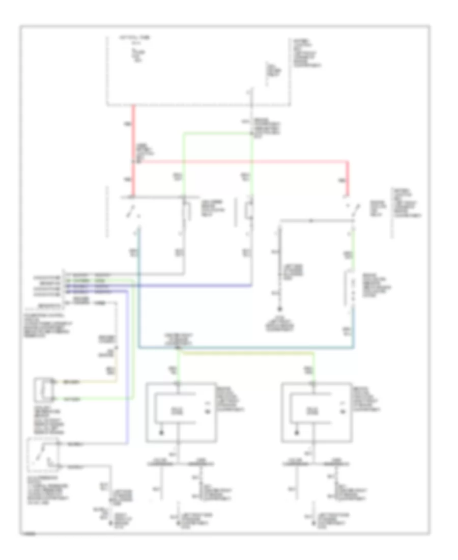
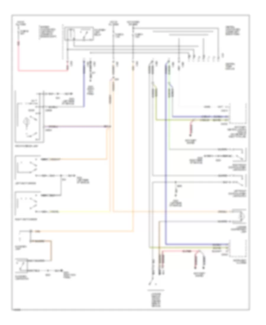
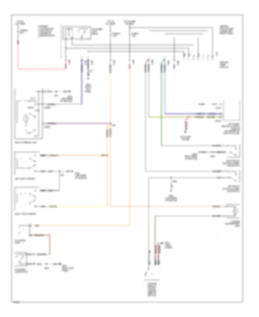
AIR CONDITIONING
Heater Wiring Diagram for Mercury Cougar S 2001
 https://portal-diagnostov.com/license.html
Automotive Electricians Portal FZCO
Automotive Electricians Portal FZCO
https://portal-diagnostov.com/license.html
https://portal-diagnostov.com/license.html
Automotive Electricians Portal FZCO
Automotive Electricians Portal FZCO
List of elements for Heater Wiring Diagram for Mercury Cougar S 2001:
- (behind right side dash panel) s274
- (bottom of right "a" pillar) g901
- (not used)
- (under right side of dash, near blower motor) heater blower series resistor
- Battery junction box (left front corner of engine compartment)
- C360
- C361
- C364
- C465
- Central junction box (under left side of dash)
- Defrost
- Defrost/ floor
- Floor
- Fuse 23 15a
- Fuse 30a
- Heater blower motor (under right side of dash, behind glove box)
- Heater blower relay
- Heater blower switch
- Heater mode switch
- High, iii
- Higher option content
- Hot at all times
- Hot in run or start
- Low, i
- Lower option content
- Med, ii
- Nca
- Not used
- Off
- Off panel/ floor
- Panel
- S166 (behind center dash panel)
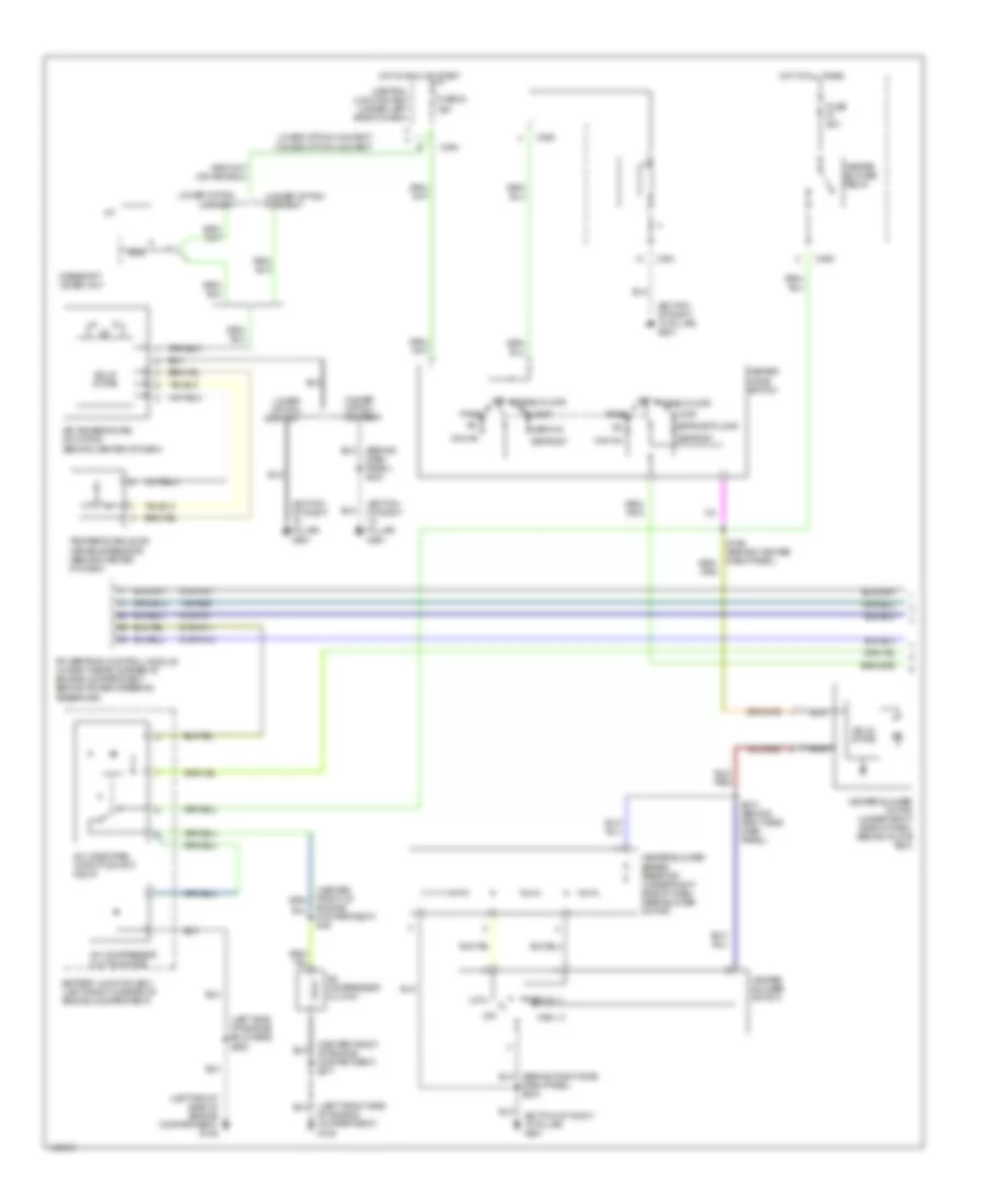
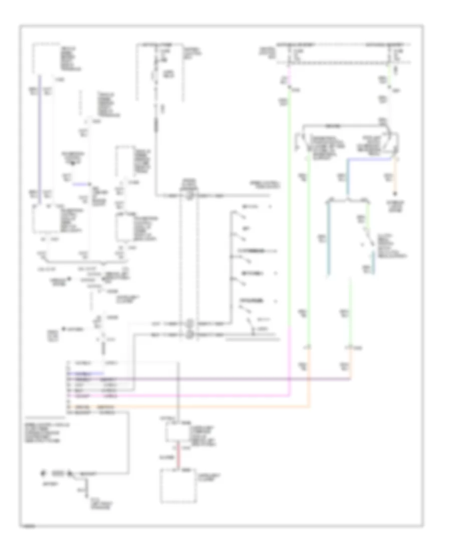
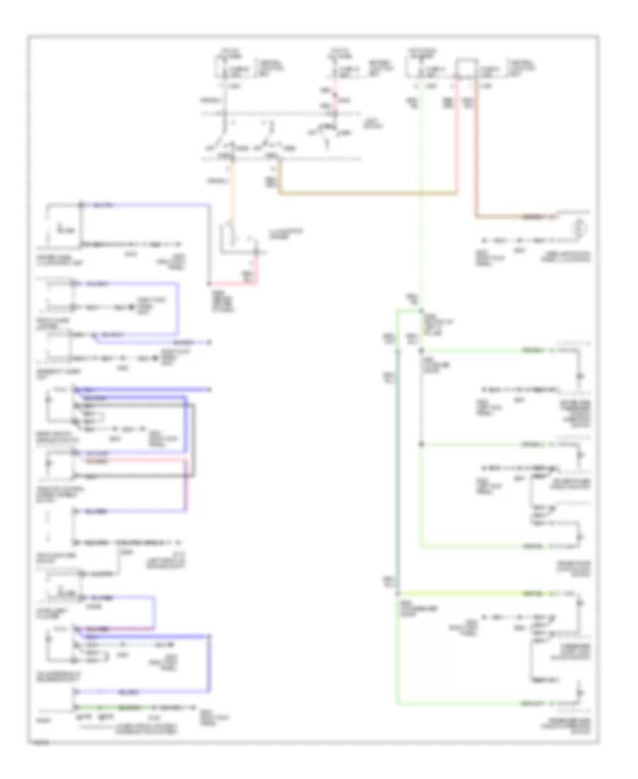
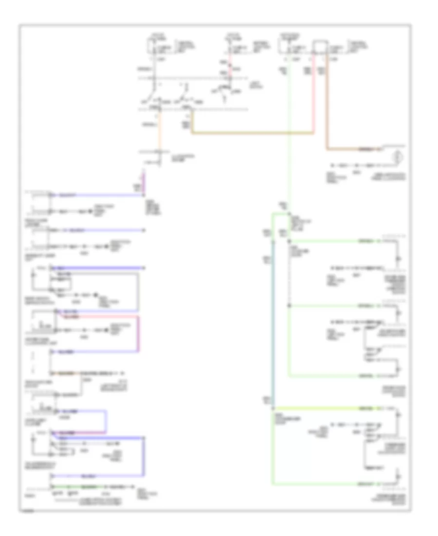
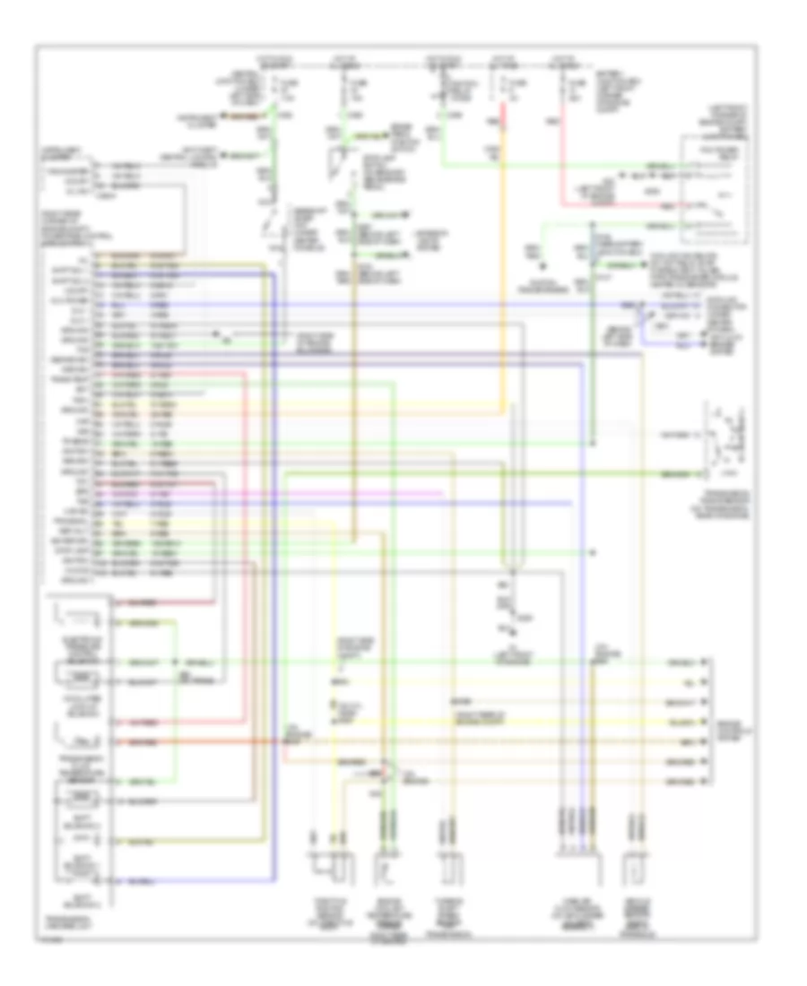
Manual A/C Wiring Diagram (1 of 2) for Mercury Cougar S 2001
List of elements for Manual A/C Wiring Diagram (1 of 2) for Mercury Cougar S 2001:
- (behind dash panel) s423
- (bottom of right "a" pillar) g901
- (center front of engine compartment) s271
- (left front side of engine compartment) g106
- (left side of engine bulkhead) s363
- 15s-re9
- 91s-fa11
- 91s-pa13
- 91s-pa17
- 91s-pa7
- A/c
- A/c compressor clutch
- A/c compressor clutch diode
- A/c wide open throttle (wot) relay
- A/t
- Air temperature actuator (behind center of dash)
- Battery junction box (left front corner of engine compartment)
- C360
- C361
- C364
- Central junction box (under left side of dash)
- Def/flr
- Defrost
- Defrost/floor
- Engine compartment) s46
- Floor
- Fuse 23 15a
- Fuse 30a
- Gearshift lever unit
- Heater blower motor (under right side of dash, behind glove box)
- Heater blower relay
- Heater blower series resistor (under right side of dash, near blower motor)
- Heater blower switch
- Heater mode switch
- High, iii
- Higher option content
- Hot at all times
- Hot in run or start
- Low, i
- Lower option content
- Lower option content higher option content
- Max a/c
- Medium, ii
- Nca
- Off
- Panel
- Panel/floor
- Powertrain control module (in right rear corner of engine compartment, behind power steering reservoir)
- S166 (behind center dash panel)
- S274 (behind right side dash panel)
- Solid state
- Temperature door variable resistor (behind center of dash)
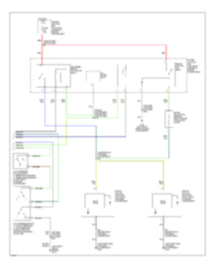
Manual A/C Wiring Diagram (2 of 2) for Mercury Cougar S 2001
List of elements for Manual A/C Wiring Diagram (2 of 2) for Mercury Cougar S 2001:
- (center front of engine compartment) s44
- (engine compartment, near battery junction box) s147
- (left front side of engine compartment) g106
- (left front side of engine) g110
- (left side of engine bulkhead) s363
- (near battery junction box) s9
- A/c compressor cycling switch (1: pressure increasing) (2: pressure decreasing) (in left front of engine compartment)
- Battery junction box (left front corner of engine compartment)
- Dual pressure switch (1: normal pressure) (2: high pressure) (in right front of engine compartment, on a/c line)
- Engine cooling fan motor (left front of engine compartment)
- Engine cooling fan relay
- Engine cooling fan resistor (below engine cooling fan motor)
- Fuse 60a
- G106 (left front side of engine compartment)
- High speed engine cooling fan relay
- Hot at all times
- Nca
- Pcm power relay
- Red
- S271 (center front of engine compartment)
- Second cooling fan motor (right front of engine compartment)
- Solid state
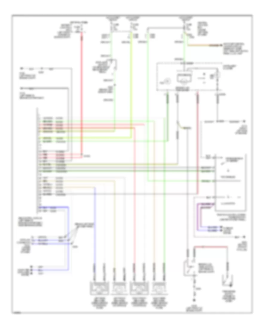
ANTI-LOCK BRAKES
Anti-lock Brake Wiring Diagrams, with Traction Control for Mercury Cougar S 2001
List of elements for Anti-lock Brake Wiring Diagrams, with Traction Control for Mercury Cougar S 2001:
- (2000) (2001)
- (behind left side of dash panel)
- 15-cf6
- 15s-cf58
- 30-cf6a
- 30-cf6b
- 31-cf6a
- 31-cf6b
- 31s-cf28
- 31s-cf45
- 31s-cf45a
- 31s-cf54
- 31s-gc6a
- 4-cf6
- 5-cf6
- 8-cf29
- 8-cf32
- 8-cf34
- 8-cf38
- 8-cf40
- 9-cf32
- 9-cf34
- 9-cf38
- 9-cf40
- Abs control module (left rear of engine compartment, near brake booster)
- Abs ind
- Anti-theft/central locking module, gearshift lever unit, headlamp switch panel illum lamp
- Brake fluid level switch (left rear of engine compt)
- Brake fluid/ park brake
- C362
- C365 c365
- C369 c369
- C808b
- Central junction box (under left side of dash)
- Computer data lines system
- Connector (dlc) (under center of dash)
- Data link
- Disable/enable switch
- Fuse 15a
- Fuse 60a
- Fuse 7.5a
- G106 (left front of engine compt)
- G110 (front left side of engine)
- G116 (left rear of engine compartment)
- G203 (bottom of right "a" pillar)
- Hot at all times battery junction box (left front corner of engine compt)
- Hot in start or run
- Illumination
- Instrument cluster
- Interior lights system
- Left front abs wheel speed sensor (on spindle)
- Left rear abs wheel speed sensor (on backing plate)
- Nca
- Park brake switch (at base of park brake lever)
- Processor
- Red
- Right front abs wheel speed sensor (on spindle)
- Right rear abs wheel speed sensor (on backing plate)
- S1002
- S281
- S282
- S359
- S360
- S363
- S364
- S367 (behind left side of dash)
- Stoplamp switch (on bracket above brake pedal)
- Tcs
- Tcs disabled
- Traction control system disable switch (center of dash panel)
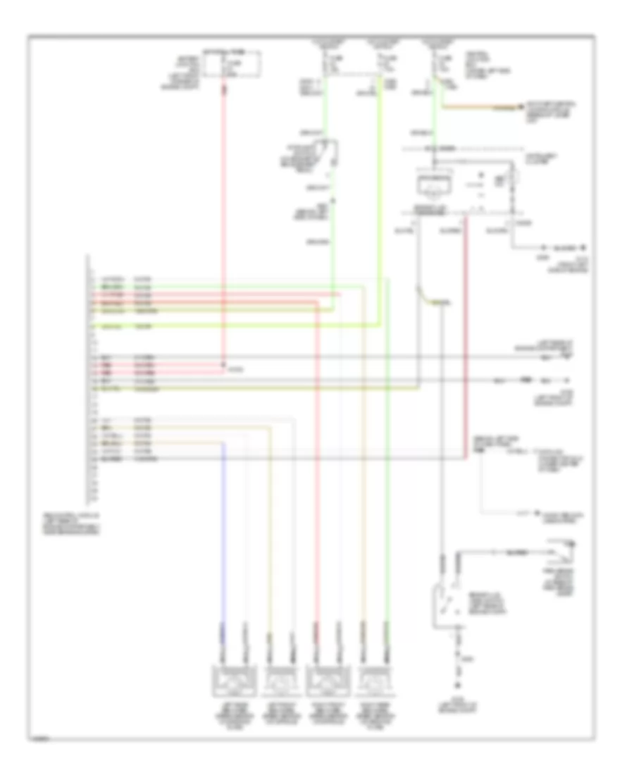
Anti-lock Brake Wiring Diagrams, without Traction Control for Mercury Cougar S 2001
List of elements for Anti-lock Brake Wiring Diagrams, without Traction Control for Mercury Cougar S 2001:
- (2000) (2001)
- (behind left side of dash panel) s364
- (left rear of engine compartment) g116
- 15-cf6
- 15s-cf58
- 30-cf6a
- 30-cf6b
- 31-cf6a
- 31-cf6b
- 31s-cf28
- 31s-gc6a
- 8-cf29
- 8-cf32
- 8-cf34
- 8-cf38
- 8-cf40
- 9-cf32
- 9-cf34
- 9-cf38
- 9-cf40
- Abs control module (left rear of engine compartment, near brake booster)
- Abs ind
- Anti-theft/central locking module, gearshift lever unit
- Battery junction box (left front corner of engine compt)
- Brake fluid level switch (left rear of engine compt)
- Brake fluid/ park brake
- C362
- C369 c369
- C808b
- Central junction box (under left side of dash)
- Computer data lines system
- Data link connector (dlc) (under center of dash)
- Fuse 15a
- Fuse 60a
- Fuse 7.5a
- G106 (left front of engine compt)
- G110 (front left side of engine)
- Hot at all times
- Hot in start or run
- Instrument cluster
- Left front abs wheel speed sensor (on spindle)
- Left rear abs wheel speed sensor (on backing plate)
- Nca
- Park brake switch (at base of park brake lever)
- Processor
- Red
- Right front abs wheel speed sensor (on spindle)
- Right rear abs wheel speed sensor (on backing plate)
- S1002
- S359
- S360
- S363
- S367 (behind left side of dash)
- Stoplamp switch (on bracket above brake pedal)
ANTI-THEFT
Forced Entry Wiring Diagram (1 of 2) for Mercury Cougar S 2001
List of elements for Forced Entry Wiring Diagram (1 of 2) for Mercury Cougar S 2001:
- (right 'a' pillar) s6
- (right rear corner of engine compt) powertrain control module
- (w/ remote control
- 14-aa17
- 2.0l
- 2.5l
- 29-aa17
- 29s-aa27
- 31-aa17
- 31-aa57
- 31s-aa30
- 31s-aa61
- 31s-aa61a
- 31s-aa62
- 31s-aa62a
- 31s-aa63
- 31s-aa63a
- 31s-aa64
- 31s-aa64a
- 31s-gl15
- 31s-gl20
- 31s-gl24
- 31s-gl27
- 31s-gl46
- 31s-gl47
- 31s-gl6
- 31s-gl7
- 32-aa34
- 32-aa65
- 32-aa66
- 33-aa34
- 33-aa59
- 33-aa60
- 49-gl26
- 8-aa36
- 8-aa6
- Anti-theft horn (right side luggage compt)
- Anti-theft/ central locking module (on center of right 'a' pillar)
- C23
- C360
- C361
- C362
- C366
- C421
- C443b
- C451a
- C451b
- Central junction box (under left side of dash)
- Central locking)
- Central timer module
- Data link connector (under center of dash)
- Driver door lock/ unlock switch
- Fuse 25 20a
- Fuse 30 7.5a
- Fuse 34 7.5a
- G200 (left kick panel)
- G203 (right kick panel)
- G405 (right rear of vehicle)
- Hot at all times
- Hot in run or start
- Interior lights system
- Lock
- Passenger door lock/unlock switch
- Pats indicator
- Radio
- S257
- S258
- S354
- S7 (right 'a' pillar)
- Tailgate/ decklid anti-theft inhibit switch (right rear of vehicle)
- Trunk/tailgate fuel door release system
- Unlk
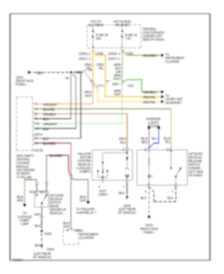
Forced Entry Wiring Diagram (2 of 2) for Mercury Cougar S 2001
List of elements for Forced Entry Wiring Diagram (2 of 2) for Mercury Cougar S 2001:
- (left front of engine compt) g106
- (right "a" pillar)
- (right kick panel) g203
- (w/ remote control
- 31s-ge11
- 31s-ge7
- 31s-ge9
- Anti-theft flasher relay (on base of right "a" pillar)
- Battery junction box (left front corner of engine compt)
- C23
- C366
- C372
- C808a
- Central junction box (under left side of dash)
- Central locking)
- Central timer module (under left side of dash, on central junction box)
- Driver side door lock motor
- Engine compartment switch (left front of engine compt)
- Exterior lights system
- Fuse 23 15a
- Fuse 7 20a
- G200 (left kick panel)
- G203 (right kick panel)
- G404 (left rear of vehicle)
- G405 (right rear of vehicle)
- High option content
- Hot at all times
- Hot in run or start
- Instrument cluster
- Interior lights system
- Left front door courtesy lamp switch
- Liftgate/ decklid switch (center rear of vehicle)
- Low option content
- Nca
- Passenger side door lock motor
- Right front door courtesy lamp switch
- S257
- S258
- S354
- S355
- S362
- S370 (right "a" pillar)
- S371
- S423
- Tailgate ajar relay 1 (behind right side of dash)
- Tailgate ajar relay 2 (behind right side of dash)
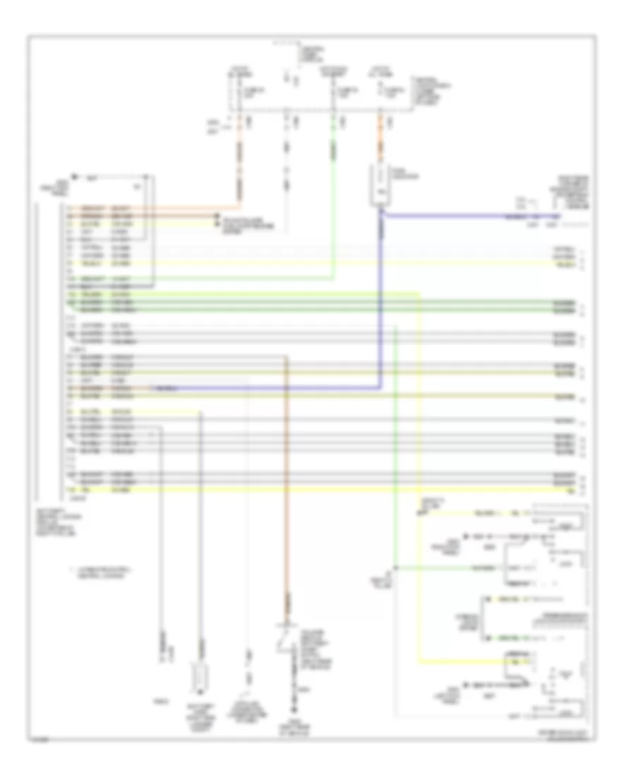
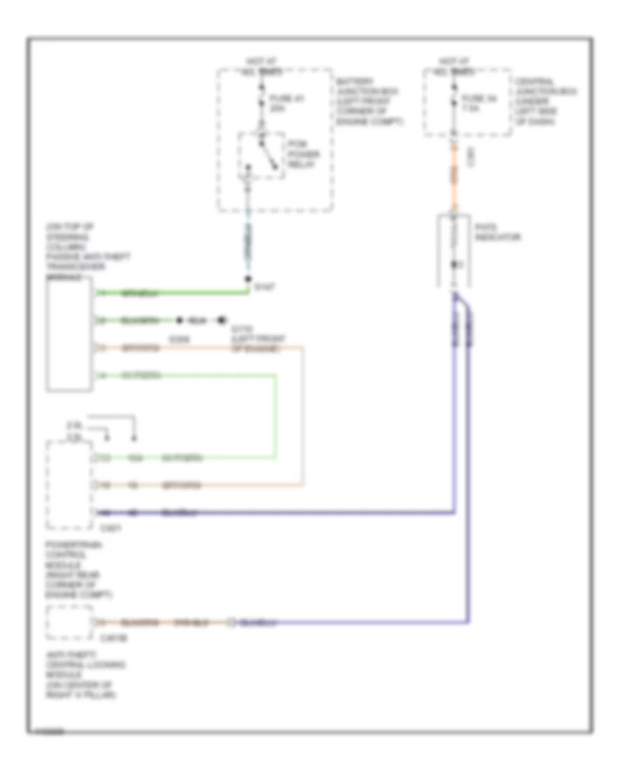
Passive Anti-theft Wiring Diagram for Mercury Cougar S 2001
List of elements for Passive Anti-theft Wiring Diagram for Mercury Cougar S 2001:
- (on top of steering column) passive anti-theft transceiver module
- 2.0l
- 2.5l
- 31s-gl6
- Anti-theft/ central locking module (on center of right 'a' pillar)
- Battery junction box (left front corner of engine compt)
- C361
- C421
- C451b
- Central junction box (under left side of dash)
- Fuse 34 7.5a
- Fuse 41 20a
- G110 (left front of engine)
- Hot at all times
- Pats indicator
- Pcm power relay
- Powertrain control module (right rear corner of engine compt)
- S147
- S359
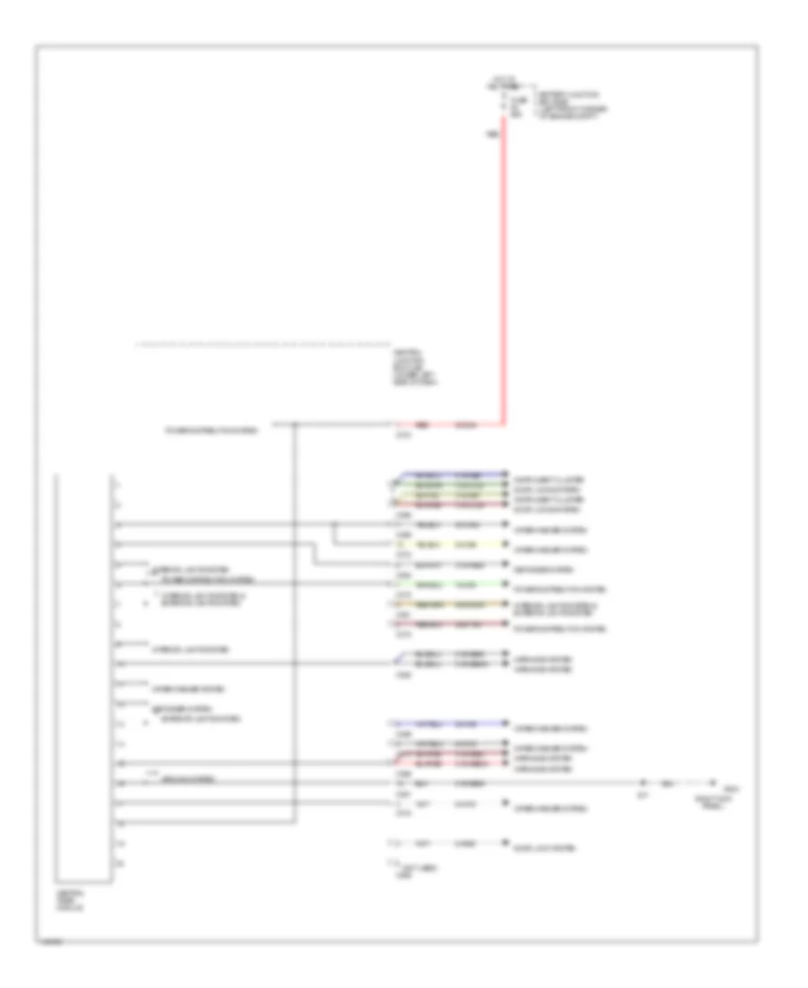
BODY COMPUTER
Body Computer Wiring Diagrams for Mercury Cougar S 2001
List of elements for Body Computer Wiring Diagrams for Mercury Cougar S 2001:
- (not used)
- (right kick panel)
- 15-da2
- 30-da4
- 30s-dd40
- 30s-ta31
- 31s-ge49
- 31s-ge49a
- 31s-ge52
- 31s-ge52a
- 31s-ge7
- 31s-ge9
- 31s-hb29
- 31s-lc29
- 31s-lc30
- 32-ka9
- 33-ka34
- 33-ka6
- 8-aa36
- 8-ka18
- 8-ka19
- Battery junction box (bjb) (left front corner of engine compt)
- C361
- C362
- C364
- C366
- C369
- C370
- C372
- Central junction box (cjb) (under left side of dash)
- Central timer module
- Defogger system
- Door lock system
- Door locks system
- Exterior lights system
- Fuse 60a
- G203
- Ground system
- Hot at all times
- Instrument cluster
- Interior lights system
- Interior lights system & exterior lights system
- Power distribution system
- Red
- S17
- Warnings system
- Wiper/washer system
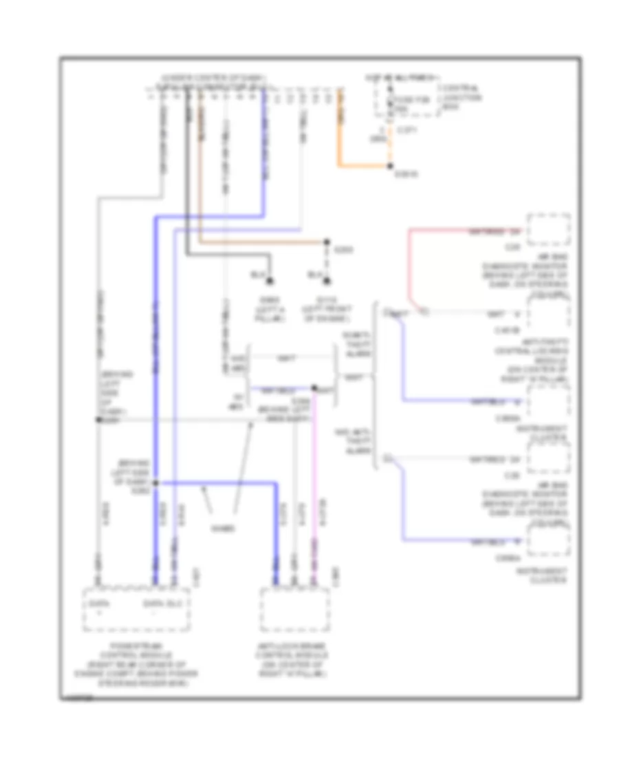
COMPUTER DATA LINES
Computer Data Lines for Mercury Cougar S 2001
List of elements for Computer Data Lines for Mercury Cougar S 2001:
- (behind left side of dash) s281
- (behind left side of dash) s282
- (under center of dash) data link connector (dlc)
- 4-cf6
- 4-re8
- 5-cf6
- 5-re8
- 8-cf29
- 8-ra1
- Air bag diagnostic monitor (behind left side of dash, on steering column)
- Anti-lock brake control module (on center of right "a" pillar)
- Anti-theft/ central locking module (on center of right "a" pillar)
- C20
- C371
- C385
- C421
- C451b
- C808a
- Central junction box
- Data +
- Data -
- Dlc
- Fuse f28 30a
- G110 (left front of engine)
- G900 (left a pillar)
- Hot at all times
- Instrument cluster
- Powertrain control module (right rear corner of engine compt, behind power
- S250
- S3010
- S364 (behind left side dash)
- Steering reservoir)
- W/ abs
- W/abs
- W/anti- theft alarm
- W/o abs
- W/o anti- theft alarm
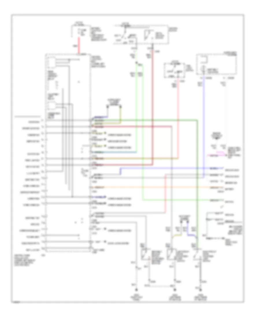
COOLING FAN
Cooling Fan Wiring Diagram for Mercury Cougar S 2001
List of elements for Cooling Fan Wiring Diagram for Mercury Cougar S 2001:
- (center front of engine compartment) s44
- (engine compartment, near battery junction box) s147
- (left front side of engine compartment) g106
- (left side of engine bulkhead) s250
- (left side of engine bulkhead) s363
- (near battery junction box) s9
- (right front of engine) g119
- 8-rj6
- 9-re8
- 91s-pa13
- 91s-pa17
- 91s-pa7
- Battery junction box (left front corner of engine compartment)
- Compartment)
- Coolant temperature sensor (2.5l: on right rear of engine) (2.0l: on left rear of engine)
- Dual pressure switch (1: normal pressure) (2: high pressure) (in right front of engine compartment, on a/c line)
- Engine cooling fan motor (left front of engine compartment)
- Engine cooling fan relay
- Engine cooling fan resistor (below engine cooling fan motor)
- Fuse 60a
- G106 (left front side of engine compartment)
- Gnd switched
- High speed engine cooling fan relay
- Hot at all times
- Nca
- Of engine compartment) g106
- Pcm power relay
- Powertrain control module (in right rear corner of engine compartment, behind power steering reservoir)
- Red
- S271 (center front of engine compartment)
- S48 (engine)
- Second cooling fan motor (right front of engine compartment)
- Sensor rtn
- Sensor sig
- Solid state
- W/air conditioning
- W/o air conditioning
CRUISE CONTROL
Cruise Control Wiring Diagram for Mercury Cougar S 2001
List of elements for Cruise Control Wiring Diagram for Mercury Cougar S 2001:
- 14-pg12
- 2.0l
- 2.5l w/ a/t
- 2.5l w/ m/t
- 29s-pg16
- 29s-pg17
- 31-pg13
- 8-pg11
- 8-pg13
- 8-pg18
- 91-pg12
- A/t
- Air bag sliding contact
- Battery
- Battery junction box
- Brake pedal position switch (under left side of dash, on brake pedal support)
- C141
- C1899
- C236
- C333
- C369
- C421
- C440
- C808
- C808b
- C823
- Clutch pedal position switch (on clutch pedal support)
- Coast/resume
- Decelerate
- Exterior lights system
- Fuse 15a
- G110 (left front of engine)
- Horn
- Horn relay
- Hot at all times
- Hot in run or start
- Hot in run or start central junction box
- Instrument cluster
- Instrument interface module (behind left side of dash)
- M/t
- Nca
- Off
- Powertrain control module
- Powertrain control module (rear right of eng compt)
- Radio (w/ a/c only)
- S136
- S351
- S60 (center of engine compt)
- Set/accel
- Side of dash) s18
- Speed control module (in left rear corner of engine compartment, near strut tower)
- Speed control/ horn switch
- Stoplamp switch (on bracket, above brake pedal)
- Vehicle speed sensor (lower rear of trans)
- Vehicle speed sensor (right side of transaxle)
- Warning system
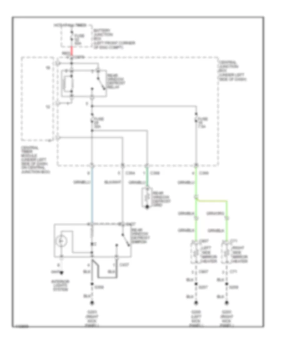
DEFOGGERS
Defogger Wiring Diagram for Mercury Cougar S 2001
List of elements for Defogger Wiring Diagram for Mercury Cougar S 2001:
- Battery junction box (left front corner of eng compt)
- C364
- C366
- C368
- C370
- C437
- C71
- C807
- Central junction box (under left side of dash)
- Central timer module (under left side of dash, on central junction box)
- Fuse 30a
- Fuse 60a
- Fuse 7.5a
- G200 (left kick panel)
- G203 (right kick panel)
- Hot at all times
- Interior lights system
- Left side mirror heater
- Rear window defrost grid
- Rear window defrost relay
- Rear window defrost switch switch
- Red
- Right side mirror heater
- S257
- S258
- S358
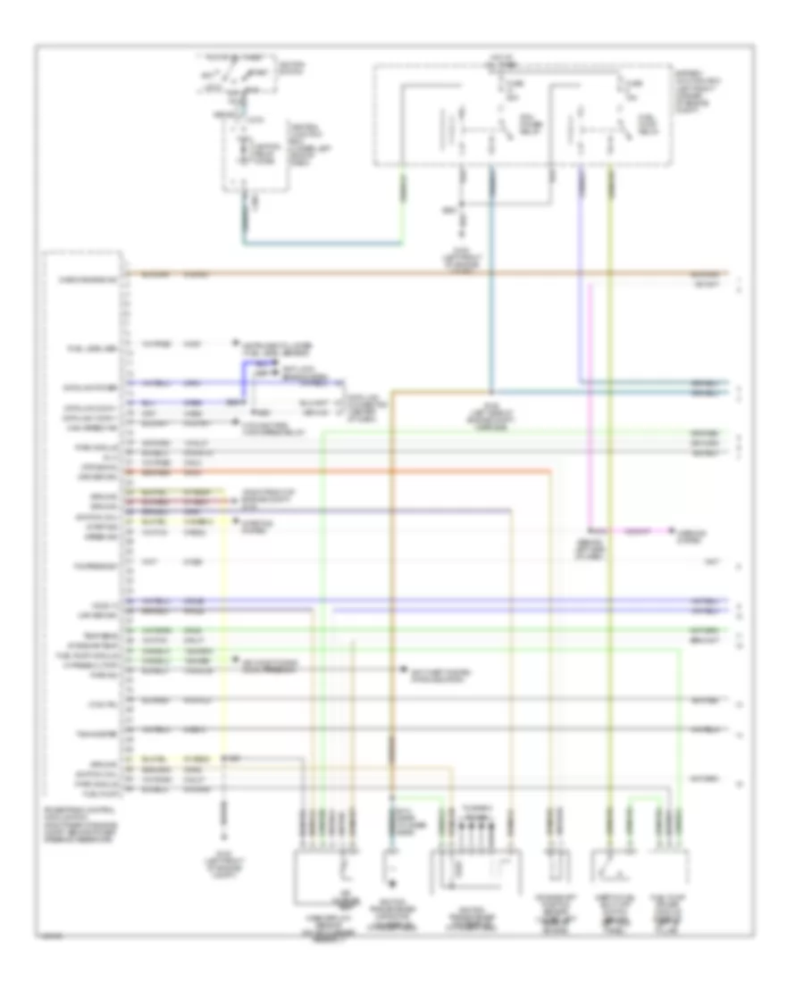
ENGINE PERFORMANCE
2.0L
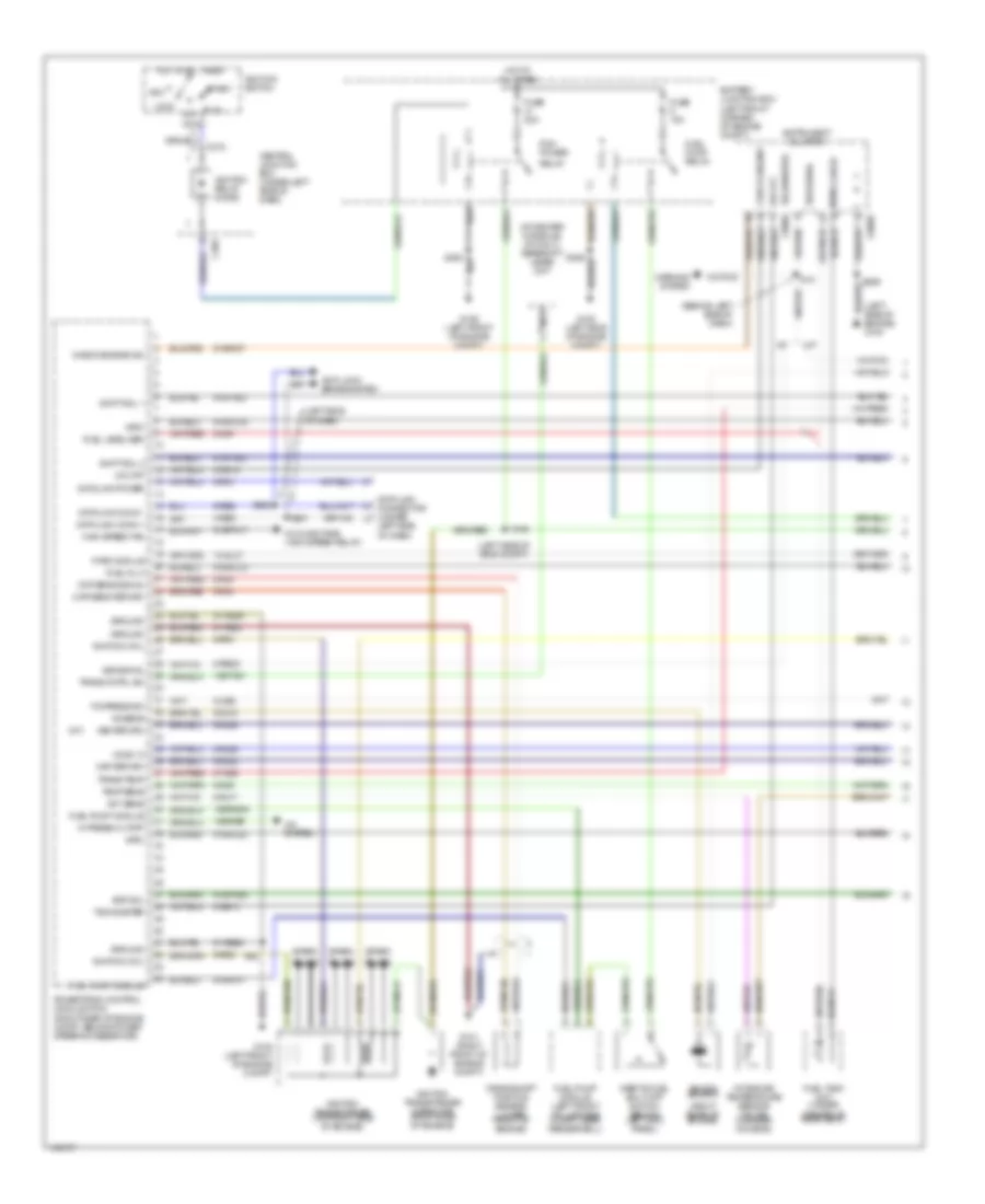
2.0L, Engine Performance Wiring Diagrams (1 of 3) for Mercury Cougar S 2001
List of elements for 2.0L, Engine Performance Wiring Diagrams (1 of 3) for Mercury Cougar S 2001:
- (behind left side of dash)
- (right front of engine compt) g101
- 10-gl37
- 15s-re16
- 15s-re9
- 31s-bb12
- 31s-gl36
- 4-re8
- 5-re8
- 8-ce6
- 8-ga7
- 8-gb10
- 8-gl37
- 8-ra1
- 8-re22
- 8-rj17
- 8-rj25
- 8-rj4
- 8-rj6
- 9-rj22
- 9-rj4
- 9-rr1
- 9-rr2
- 91-re21
- 91-re8a
- 91-re8c
- 91s-pa17
- 91s-rd7
- 91s-rh5
- 91s-rl12
- 91s-rl27
- Acc
- Air charge temp
- Air conditioning (dual press sw)
- Anti-lock brake system
- Anti-theft system (pats indicator)
- Battery junction box (left front corner of engine compt)
- C369
- C372
- Central junction box (under left side of dash)
- Check engine ind
- Cooling fans (high speed relay)
- Cps return
- Cps signal
- Crankshaft position sensor (lower left rear of engine)
- Cta ctrl
- Data link conn +
- Data link conn -
- Data link connector (center
- Data link power
- Fuel level sen
- Fuel pump
- Fuel pump driver module (rear of left "b" pillar)
- Fuel pump module
- Fuel pump relay
- Fuse 15a
- Fuse 20a
- G100 (left front of engine compt)
- Ground
- Hi press cutoff
- High speed fan
- Ho2s 12
- Hot at all times
- Ignition coil
- Ignition relay diode
- Ignition switch
- Ignition transformer (on rear of cylinder head)
- Ignition transformer capacitor (on rear of cylinder head)
- Inertia fuel shut-off switch (behind left kick panel)
- Inj 3
- Instrument cluster (fuel level sensor)
- Intake air temp
- Lock
- Maf return
- Mass airflow sensor (on air cleaner assembly)
- Of dash)
- Off
- P/s press sw
- Pats ind
- Pats module
- Pcm power relay
- Plugs
- Powertrain control module (pcm) (right rear of engine compt, behind power steering reservoir)
- Run
- S146 (left side of engine compt, near bjb)
- S18
- S281
- S282
- S363
- S414 (near cylinder head)
- S62
- Speed sig
- Start
- Start sig
- Starting system
- Tachometer
- Temp sens
- To spark
- Warning system
2.0L, Engine Performance Wiring Diagrams (2 of 3) for Mercury Cougar S 2001
List of elements for 2.0L, Engine Performance Wiring Diagrams (2 of 3) for Mercury Cougar S 2001:
- (behind left side of dash)
- (on clutch pedal support) clutch pedal position switch
- (on right side of engine)
- (top of engine)
- (top of steering column)
- Battery junction box (left front corner of engine compt)
- C808a
- C808b
- Check engine
- Engine coolant temperature sensor (upper left rear of engine)
- Fuel rail pressure transducer sensor (center front of engine)
- Fuel tank pressure transducer sensor (on fuel tank)
- Fuse 20a
- Heated oxygen
- Instrument cluster
- Knock sensor
- Nca
- Passive anti-theft transceiver module
- Power steering pressure switch (on left front of engine)
- S3005 (left rear side of engine)
- S406
- S425
- S48
- S53 (rear of engine)
- S54 (right side of engine)
- Sensor (ho2s) (front 11) (on left side of engine, in exhaust manifold)
- Sensor (ho2s) (rear 12) (on left side of engine, in exhaust, behind converter)
- Speedo- meter
- Tacho- meter
- Throttle position sensor (on throttle body)
2.0L, Engine Performance Wiring Diagrams (3 of 3) for Mercury Cougar S 2001
List of elements for 2.0L, Engine Performance Wiring Diagrams (3 of 3) for Mercury Cougar S 2001:
- (at cylinder head) s47
- (center of engine compt)
- (left front of engine compt) g100
- (on fuel tank)
- (right front of engine) generator
- (right rear of engine compt) evap canister purge valve
- 15-re8
- 15-re8a
- 29-re8
- 7-re8
- 8-ba9
- 8-bb6
- 8-rj11
- 8-rj13
- 8-rj14
- 8-rj18
- 8-rj22
- 8-rj28
- 8-rj29
- 8-rj3
- 9-re8
- 9-rj18
- 9-rj3
- 91-re8
- 91-re8b
- 91s-fa11
- 91s-pa13
- 91s-pa7
- 91s-rj14
- 91s-rj25
- 91s-rl10
- 91s-rl11
- 91s-rl13
- 91s-rl25
- 91s-rl3
- 91s-rl9
- Air conditioning
- Air conditioning (a/c wide open throttle relay)
- Battery junction box (left front of engine compt)
- Camshaft position sensor (on cylinder head, upper left rear of engine)
- Camshaft timing actuator (on top side, front of engine)
- Canister purge
- Cmp return
- Cmp sens sig
- Cooling fans (fan relay)
- Cooling fans, anti-theft, air conditioning
- Cp sw
- Dual press sw
- Evap valve
- Evaporative emission canister vent valve
- Fan relay
- Fuel inj 1
- Fuel inj 2
- Fuel inj 4
- Fuel injectors
- Fuel line press
- Fuel tank press
- Fuse 3a
- G100 (left front of engine compt)
- Generator
- Ground
- Ho2s 11
- Ho2s 12
- Hot at all times
- Iac valve
- Idle speed control valve (on upper right side of engine)
- Ignition power
- Keep alive pwr
- Knock sensor
- Ks return
- Maf sensor sig
- Powertrain control module (right rear of engine compt, behind power steering reservoir)
- Red
- Ref voltage
- S147
- S59 (center of engine compt)
- S62
- Signal control
- Tp sig signal
- Vehicle speed sensor (lower rear of transaxle)
- Vss signal
- Wot a/c relay
2.5L
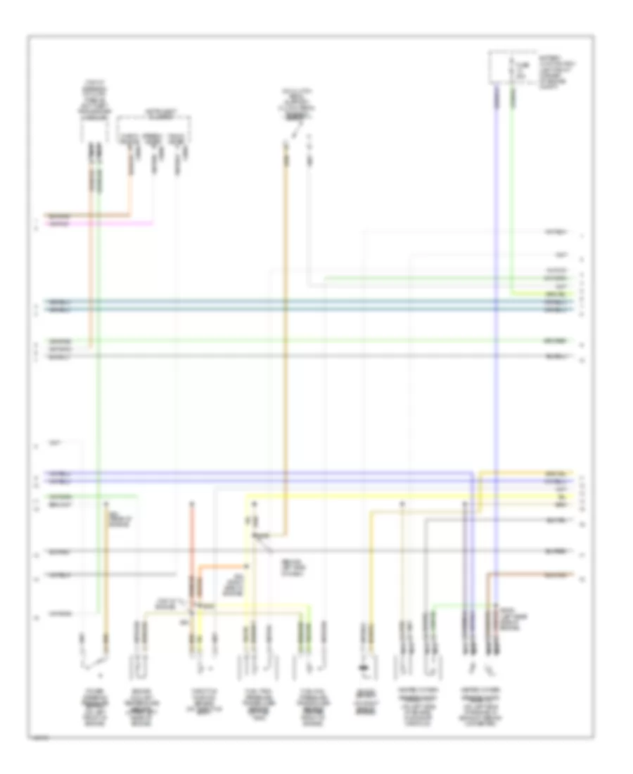
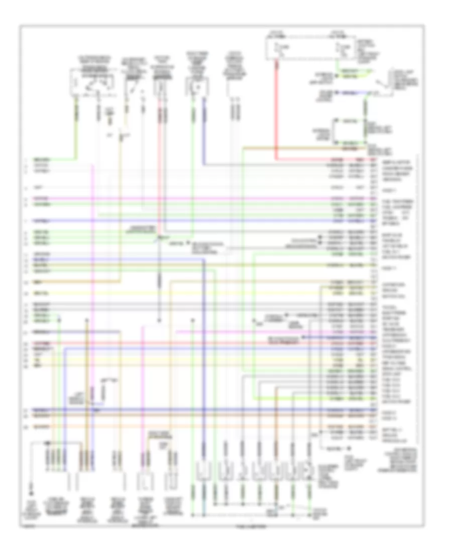
2.5L, Engine Performance Wiring Diagrams (1 of 3) for Mercury Cougar S 2001
List of elements for 2.5L, Engine Performance Wiring Diagrams (1 of 3) for Mercury Cougar S 2001:
- (a/t)
- (at center console) (a/t only) gearshift lever unit
- (behind left side of dash)
- (left side of dash)
- (left side of eng compt)
- (left side of engine) g100
- (right rear of engine)
- 10-gl37
- 15s-re16
- 15s-re9
- 15s-ta21
- 4-re8
- 5-re8
- 8-ce6
- 8-ga7
- 8-gb10
- 8-gg18
- 8-ra1
- 8-re22
- 8-rj17
- 8-rj25
- 8-rj4
- 8-rj6
- 8-ta26
- 9-rj18
- 9-rj22
- 9-rj29
- 9-rj4
- 9-rr1
- 9-rr2
- 91-re21
- 91-re8a
- 91-re8c
- 91s-pa17
- 91s-pa25
- 91s-rd7
- 91s-rht
- 91s-rj16
- 91s-rl12
- 91s-rl20
- 91s-ta23
- 91s-ta24
- A/c system
- A/t
- Acc
- Act sens
- Anti-lock brake system
- Battery junction box (left front corner of engine compt)
- C369
- C372
- C808b
- Central junction box (under left side of dash)
- Check engine
- Check engine ind
- Ckp sens return
- Ckp sens signal
- Cooling fans (high speed relay)
- Crankshaft position sensor (lower front of engine)
- Data link conn +
- Data link conn -
- Data link connector (under
- Data link power
- Evr sol
- Fuel gauge
- Fuel inj 3
- Fuel level sen
- Fuel pump module
- Fuel pump module (left front of luggage compt, near fenderwell)
- Fuel pump relay
- Fuel tank unit (under center of rear seat)
- Fuse 15a
- Fuse 20a
- G100 (left front of engine compt)
- G100 (left side of engine compt)
- G101 (right front of engine compt)
- G106 (left front of engine compt)
- Ground
- Hi press cutoff
- High speed fan
- Ho2s 12
- Hot at all times
- Ignition coil
- Ignition relay diode
- Ignition switch
- Ignition transformer (top right side of engine)
- Ignition transformer capacitor (right side of engine)
- Imrc
- Inertia fuel shut-off switch (behind left kick panel)
- Instrument cluster
- Intake air temperature sensor (on air cleaner housing)
- Knock sensor
- Ks sens
- Left side of dash)
- Lock
- M/t
- Maf return
- Nca
- O/d off
- Off
- P/s press sw
- Pats module
- Pcm power
- Plugs
- Powertrain control module (pcm) (right rear of engine compt, behind power steering reservoir)
- Relay
- Run
- S146
- S18
- S281
- S282
- S62
- Shift sol 1
- Shift sol 2
- Spark
- Start
- Tachometer
- Tachometer c808a
- Temp sens
- Trans cntrl sw
- Trans temp
- Vss return
- Vss signal
- Warning system
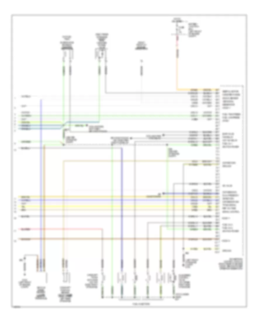
2.5L, Engine Performance Wiring Diagrams (2 of 3) for Mercury Cougar S 2001
List of elements for 2.5L, Engine Performance Wiring Diagrams (2 of 3) for Mercury Cougar S 2001:
- (a/t)
- (left side of dash)
- (m/t)
- (on engine)
- (on top center of engine) electronic vacuum regulator solenoid valve
- (on top of engine) intake manifold
- (right side of engine) s54
- (top of transmission)
- Battery junction box (left front corner of engine compt)
- C104
- Electric pressure control solenoid
- Engine coolant temperature sensor (upper right rear of engine)
- Exhaust pressure transducer sensor (right rear of engine)
- Fuel rail pressure transducer sensor (top rear of engine)
- Fuel tank pressure transducer sensor (on fuel tank)
- Fuse 20a
- G100 (left front of engine compt)
- Heated oxygen sensor (ho2s) (front 11) (right side of engine, in exhaust manifold)
- Heated oxygen sensor (ho2s) (front 21) (left side of engine, in exhaust manifold)
- Heated oxygen sensor (ho2s) (rear) (right side of engine, behind converter)
- Modulated lockup solenoid
- Nca
- Power steering pressure switch (right front of engine)
- Runner control module
- S3005
- S406
- S407
- S425
- S48 (top of engine)
- S53 (rear of engine)
- S62
- Shift solenoids
- Throttle position sensor (on throttle body)
- Transmission hardware unit
- Transmission oil temperature sensor
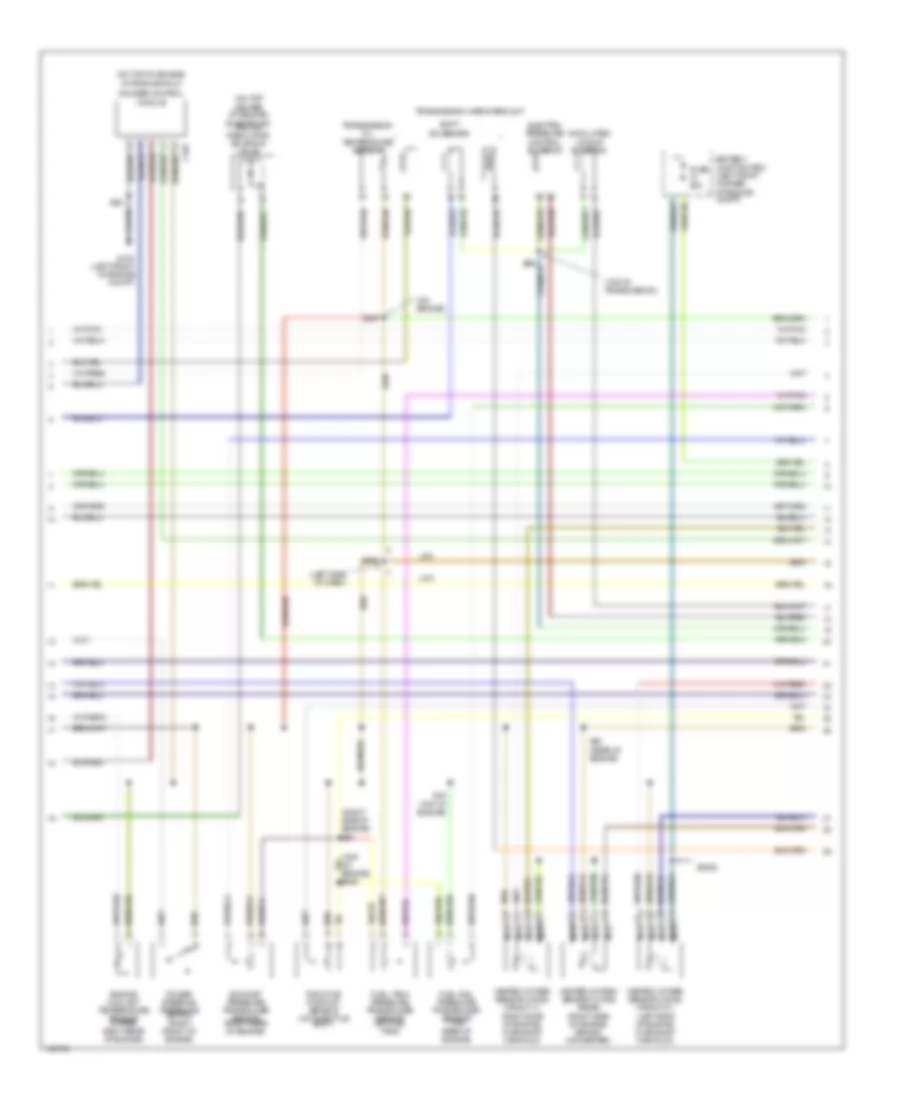
2.5L, Engine Performance Wiring Diagrams (3 of 3) for Mercury Cougar S 2001
List of elements for 2.5L, Engine Performance Wiring Diagrams (3 of 3) for Mercury Cougar S 2001:
- (a/t)
- (behind left side of dash)
- (left rear of engine)
- (m/t)
- (near battery junction block)
- (near engine)
- (on bracket, above clutch pedal) clutch pedal position switch
- (on fuel tank)
- (on transmission, rear of engine)
- (right rear of engine compt) evap canister purge valve
- (right side of engine)
- (top of engine) s50
- (top of steering column)
- 15-re8
- 15-re8a
- 15s-re13
- 29-re8
- 31s-ta9
- 7-re8
- 8-bb6
- 8-gl37
- 8-rj11
- 8-rj13
- 8-rj14
- 8-rj15
- 8-rj18
- 8-rj22
- 8-rj28
- 8-rj29a
- 8-rj3
- 8-rj7
- 8-ta27
- 8-ta9
- 9-re8
- 9-re8a
- 9-rr3
- 91-re8
- 91-re8b
- 91s-fa11
- 91s-pa13
- 91s-pa7
- 91s-rj14
- 91s-rj15
- 91s-rj25
- 91s-rl10
- 91s-rl11
- 91s-rl13
- 91s-rl14
- 91s-rl15
- 91s-rl25
- 91s-rl3
- 91s-rl9
- 91s-ta17
- 91s-ta20
- 91s-ta25
- A/t
- Air conditioning
- Air conditioning (dual press sw)
- Air conditioning, anti-theft, cooling fans
- Battery junction box (left front of engine compt)
- Camshaft position sensor (front of engine)
- Canister purge
- Cmp return
- Cmp sens sig
- Cooling fans
- Cp sw
- Cruise system control
- Dual press sw
- Elect press
- Ept sens
- Evap valve
- Evaporative emission canister vent valve
- Exterior lights (bpp switch)
- Exterior lights system
- Fan relay
- Fuel inj 1
- Fuel inj 2
- Fuel inj 4
- Fuel inj 5
- Fuel inj 6
- Fuel injectors
- Fuel line press
- Fuel tank press
- Fuse 15a
- Fuse 3a
- G100 (left front of engine compt)
- Ground
- Ho2s 11
- Ho2s 12
- Ho2s 21
- Hot at all times
- Iac valve
- Idle speed control valve (upper right side of engine)
- Ignition coil
- Ignition power
- Keep alive pwr
- Knock sensor
- M/t
- Maf sensor sig
- Mass air- flow sensor (on rear of air cleaner assembly)
- Not used
- Passive anti-theft transceiver module
- Pats module
- Powertrain control module (right rear of engine compt, behind power steering reservoir)
- Red
- Ref voltage
- S130 (behind left side of dash)
- S147
- S366 (a/t)
- S51
- S59
- S60
- S62
- Shft sol 3
- Signal control
- Start sig
- Starting system
- Stop lamp
- Stop lamp switch (on bracket, above brake pedal)
- Tcc sol
- Tp sig signal
- Tr sens
- Transmission range sensor
- Tss sensor
- Turbine shaft speed sensor (a/t) (lower left rear of engine compt)
- Vehicle speed sensor (a/t) (right side of transaxle)
- Vehicle speed sensor (m/t) (right side of transaxle)
- Vss signal
- Wot a/c relay
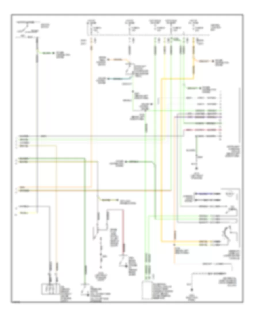
EXTERIOR LIGHTS
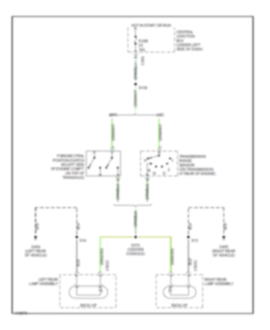
Backup Lamps Wiring Diagram for Mercury Cougar S 2001
List of elements for Backup Lamps Wiring Diagram for Mercury Cougar S 2001:
- (a/t)
- (m/t)
- Back-up
- C369
- C502c
- C503c
- Central junction box (under left side of dash)
- Fuse 15a
- G404 (left rear of vehicle)
- G405 (right rear of vehicle)
- Hot in start or run
- Left rear lamp assembly
- Park/neutral position switch (in left side of engine compt, on top of transaxle)
- Right rear lamp assembly
- S13
- S136
- S14
- S375 (center console)
- Transmission range sensor (on transmission, at rear of engine)
Park & License Lamps Wiring Diagram for Mercury Cougar S 2001
List of elements for Park & License Lamps Wiring Diagram for Mercury Cougar S 2001:
- Battery junction box (left front corner of engine compt)
- C361
- C367
- C369
- C502d
- C502e
- C503d
- C503e
- Central junction box (under left side of dash)
- Central timer module (on central junction box)
- Daytime running lamps relay (this position empty w/o drl)
- Fuse 20a
- Fuse 7.5a
- G106 (left front of engine compt)
- G404 (left rear of vehicle)
- G405 (right rear of vehicle)
- Head
- Headlamp switch
- Headlights system
- Hot at all times
- Hot in start or run
- Left front side lamp
- Left headlight assembly
- Left license plate lamp
- Left rear lamp assembly
- Main light switch
- Nca
- Not used
- Off
- Park
- Parking lamp
- Red
- Right front side lamp
- Right headlight assembly
- Right license plate lamp
- Right rear lamp assembly
- S11 (right rear of vehicle)
- S12 (left rear of vehicle)
- S13
- S14
- S352 (left front of engine compt)
- S353 (right front of engine compt)
- S354
- S361
- S362
- S422
- Tail
- Turn/tail
- W/higher option content
- W/lower option content
Turn & Hazard & Stop Lamps Wiring Diagram for Mercury Cougar S 2001
List of elements for Turn & Hazard & Stop Lamps Wiring Diagram for Mercury Cougar S 2001:
- (left rear of vehicle) s16
- (right rear of vehicle) s15
- 49a
- Anti-lock brakes system
- Anti-theft flasher relay (at base of right "a" pillar)
- Anti-theft flasher relay (on base of right "a" pillar)
- Battery junction box (left front corner of engine compt)
- C2107
- C362
- C367
- C369
- C372
- C459
- C502a
- C502b
- C502d
- C503a
- C503b
- C503d
- C808a
- C808b
- Central junction box (under left side of dash)
- Engine controls system
- Fuse 15a
- Fuse 20a
- G106 (left front of engine compt)
- G110 (left front of engine)
- G203 (right kick panel)
- G404 (left rear of vehicle)
- G405 (right rear of vehicle)
- Ground
- Hazard
- Hazard switches
- High mounted stoplamp
- Hot at all times
- Hot in start or run
- Instrument cluster
- Left
- Left front turn lamp
- Left rear lamp assembly
- Left side turn signal lamp
- Left turn
- Normal
- Off
- Red
- Right
- Right front turn lamp
- Right rear lamp assembly
- Right side turn signal lamp
- Right turn
- S13
- S14
- S355
- S359
- S361
- S362
- S367 (behind left side of dash)
- S423
- Stop
- Stoplamp switch (on bracket, above brake pedal)
- Turn signal relay
- Turn signal switch
- Turn signal switches
- Turn/tail
GROUND DISTRIBUTION
Ground Distribution Wiring Diagram (1 of 3) for Mercury Cougar S 2001
List of elements for Ground Distribution Wiring Diagram (1 of 3) for Mercury Cougar S 2001:
- (lower option content)
- 2-way power seat
- 2.0l
- 2.5l
- 8-way power seat
- Air bag diagnostic monitor
- Auxiliary warning system display assembly
- Battery
- Busbar
- C808b
- Clock spring
- Compartment)
- Coolant temperature sensor
- Data link connector
- Decklid motor
- Driver door lock/ unlock switch
- Driver power seat switch
- Driver power window switch
- Driver side door lock motor
- Driver side mirror motor
- Driver side passenger window operating switch
- Dual pressure switch
- Front interior lamp
- Fuel pump driver module
- Fuel tank unit
- G110 (left front of engine)
- G200 (left kick panel)
- G404 (left rear of vehicle)
- G405 (right rear of vehicle)
- G411 (on liftgate/ decklid)
- High mounted stoplamp
- Higher option content
- Instrument cluster
- Instrument interface module
- Intake manifold runner control module
- Left front door courtesy lamp switch
- Left license plate lamp
- Left rear lamp assembly
- Left vanity mirror lamp
- Liftgate/ decklid anti-theft inhibit switch
- Lower option content
- Mass airflow sensor
- Nca
- Of vehicle)
- One touch window relay
- Passive anti-theft transceiver module
- Power mirror adjust switch
- Power seat switch
- Powertrain control module
- Rear liftgate/ decklid switch
- Right front door courtesy lamp switch
- Right license plate lamp
- Right rear lamp assembly
- Right vanity mirror lamp
- S13 (right rear of vehicle)
- S250 (left side of engine firewall)
- S34 (front center of roof)
- S355 (left rear of vehicle)
- S356 (under left front seat)
- S359 (behind left side of dash)
- S8 (bottom of left "a" pillar)
- Safety belt buckle switch
- Sliding roof opening panel unit
- Speed control module
- Traction control system disable switch
- Trip computer switch
- Vehicle speed sensor
- W/ speed control
- W/o speed control
- Windshield wiper motor
Ground Distribution Wiring Diagram (2 of 3) for Mercury Cougar S 2001
List of elements for Ground Distribution Wiring Diagram (2 of 3) for Mercury Cougar S 2001:
- (2.5l)
- (right "a" pillar) s4
- Abs control module
- Air bag diagnostic monitor
- Air temperature actuator
- Anti-theft central locking module
- Belt minder module
- C361
- C421
- C504b
- C808b
- Central junction box
- Central timer module
- Courtesy lamp relay
- Data link connector
- Door)
- Fog lamp relay
- Front cigar lighter
- G116 (left rear of engine compt)
- G123 (right side of firewall)
- G203 (higher option) (right kick panel)
- G203 (lower option) (right kick panel)
- G203 (right kick panel)
- G900 (left "a" pillar)
- Gearshift lever unit
- Glove box lamp switch
- Headlight switch panel illumination lamp
- Heater blower relay
- Heater blower series resistor
- Heater blower switch
- Heater panel illumination lamp
- Ignition relay
- Instrument cluster
- Key removal inhibit solenoid
- Liftgate/ decklid release switch
- Multi- function switch
- Nca
- Passenger door lock/ unlock switch
- Passenger side door lock motor
- Passenger side mirror motor
- Passenger side window operating switch
- Powertrain control module
- Rear window defrost switch
- S17 (behind left side of dash)
- S423 (behind dash)
- S424 (behind left side of dash)
- Shield
- Tailgate ajar relay 1
- Tailgate ajar relay 2
- Traction control system (tcs) disable switch
- W/ side air bags
- W/abs
- W/o abs
- Wiper/ washer switch
Ground Distribution Wiring Diagram (3 of 3) for Mercury Cougar S 2001
List of elements for Ground Distribution Wiring Diagram (3 of 3) for Mercury Cougar S 2001:
- (canada) daytime running lights (drl) relay
- A/c compressor clutch
- A/c compressor clutch diode
- Abs control module
- Battery junction box
- Brake fluid level switch
- C443b
- C443c
- C500b
- Engine compartment switch
- Engine cooling fan motor
- Engine cooling fan relay
- Fuel pump relay
- G106 (left front of engine compt)
- G203 (higher option) (right kick panel)
- G203 (lower option) (right kick panel)
- High beam relay
- Left fog lamp
- Left front park/ turn lamp
- Left front side marker lamp
- Left front side turn signal lamp
- Left headlamp
- Low beam relay
- Low cleaning water level switch
- Low coolant level switch
- Nca
- Pcm power relay
- Radio
- Right fog lamp
- Right front park/ turn lamp
- Right front side marker lamp
- Right front side turn signal lamp
- Right headlamp
- S164 (behind center of dash)
- S271 (center front of engine compt)
- S360 (left side of engine firewall)
- S361 (center front of engine compt)
- S362 (center front of engine compt)
- S363 (left side of engine firewall)
- Second cooling fan motor
- W/air conditioning
- W/o air conditioning
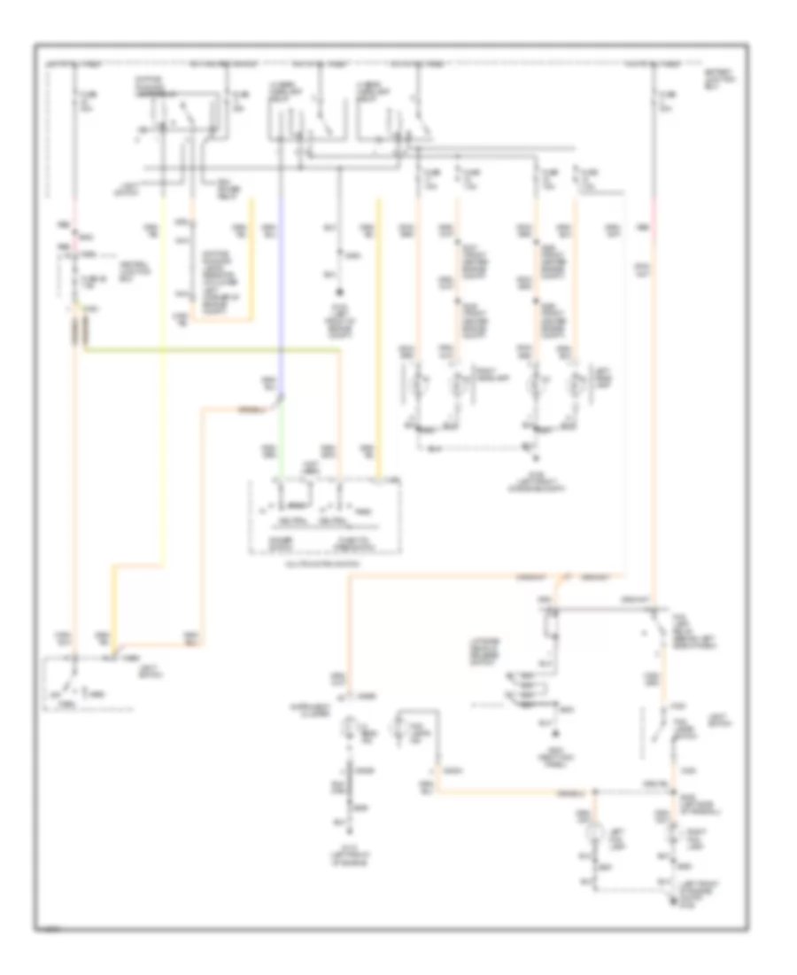
HEADLIGHTS
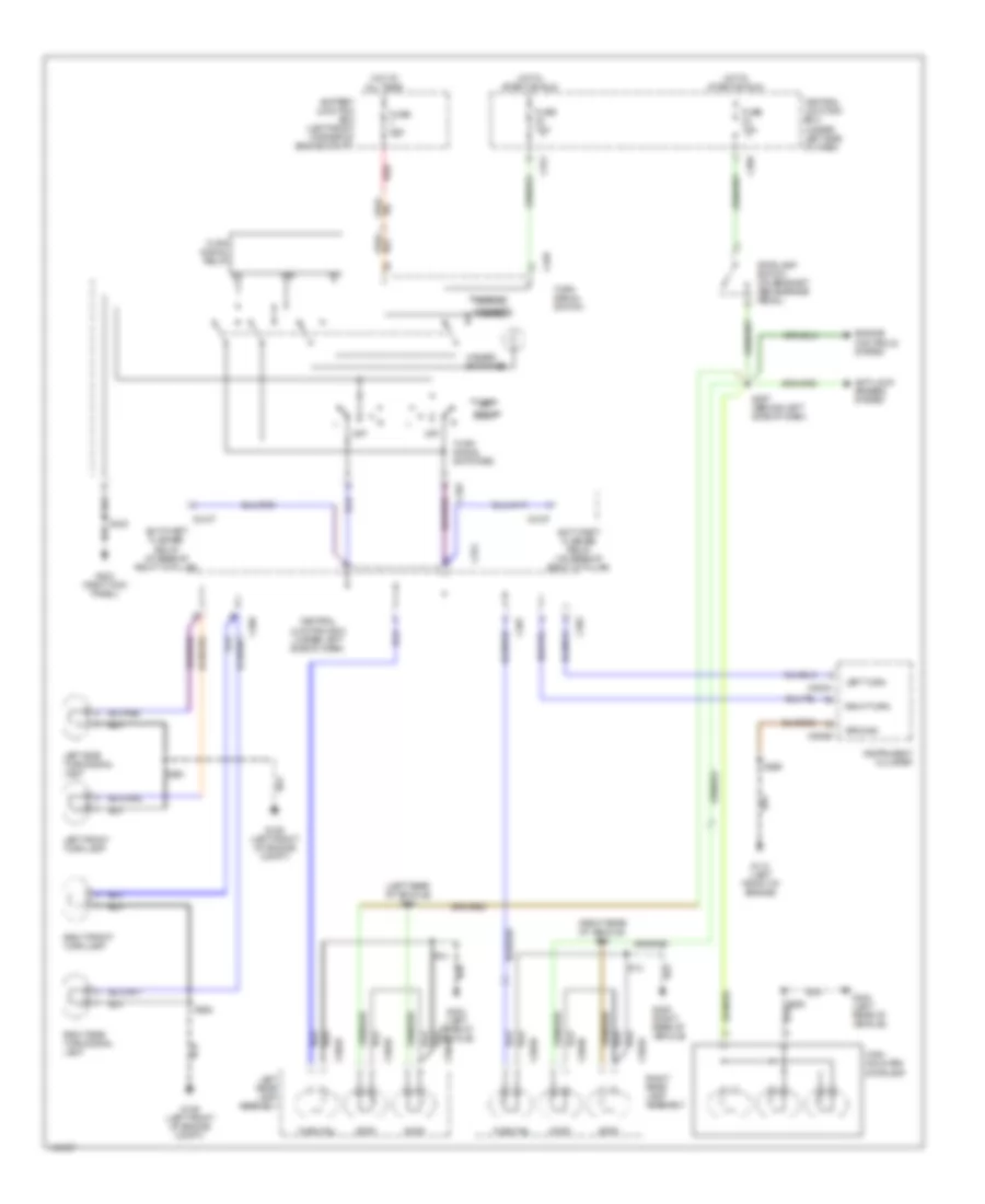
Headlight Wiring Diagram, with DRL for Mercury Cougar S 2001
List of elements for Headlight Wiring Diagram, with DRL for Mercury Cougar S 2001:
- (left front of engine compt) g106
- (not used)
- Battery junction box
- C320
- C361
- C459
- C808a
- C808b
- Central junction box
- Daytime running lamps relay
- Daytime running lamps resistor (on lower left corner of engine compt)
- Dimmer switch
- Flash-to- pass switch
- Fog lamp relay (behind left side of dash)
- Fog lamps ind
- Fog lamps switch
- Fuse 20a
- Fuse 26 7.5a
- Fuse 7.5a
- G100 (left front of engine compt)
- G106 (left front of engine compt)
- G110 (left front of engine)
- G203 (right kick panel)
- Head
- Hi beam headlamp relay
- Hi beam ind
- Hot at all times
- Hot in start or run
- Instrument cluster
- Left fog lamp
- Left head- lamp
- Liftgate/ decklid release switch
- Light switch
- Lo beam headlamp relay
- Multifunction switch
- Nca
- Neutral
- Off
- Park
- Pass
- Pcm power relay
- Red
- Right fog lamp
- Right headlamp
- S345 (front center engine compt)
- S346 (front center engine compt)
- S347 (front center engine compt)
- S348 (front center engine compt)
- S359
- S361
- S362
- S363
- S405 (left side of firewall)
- S422
- S423
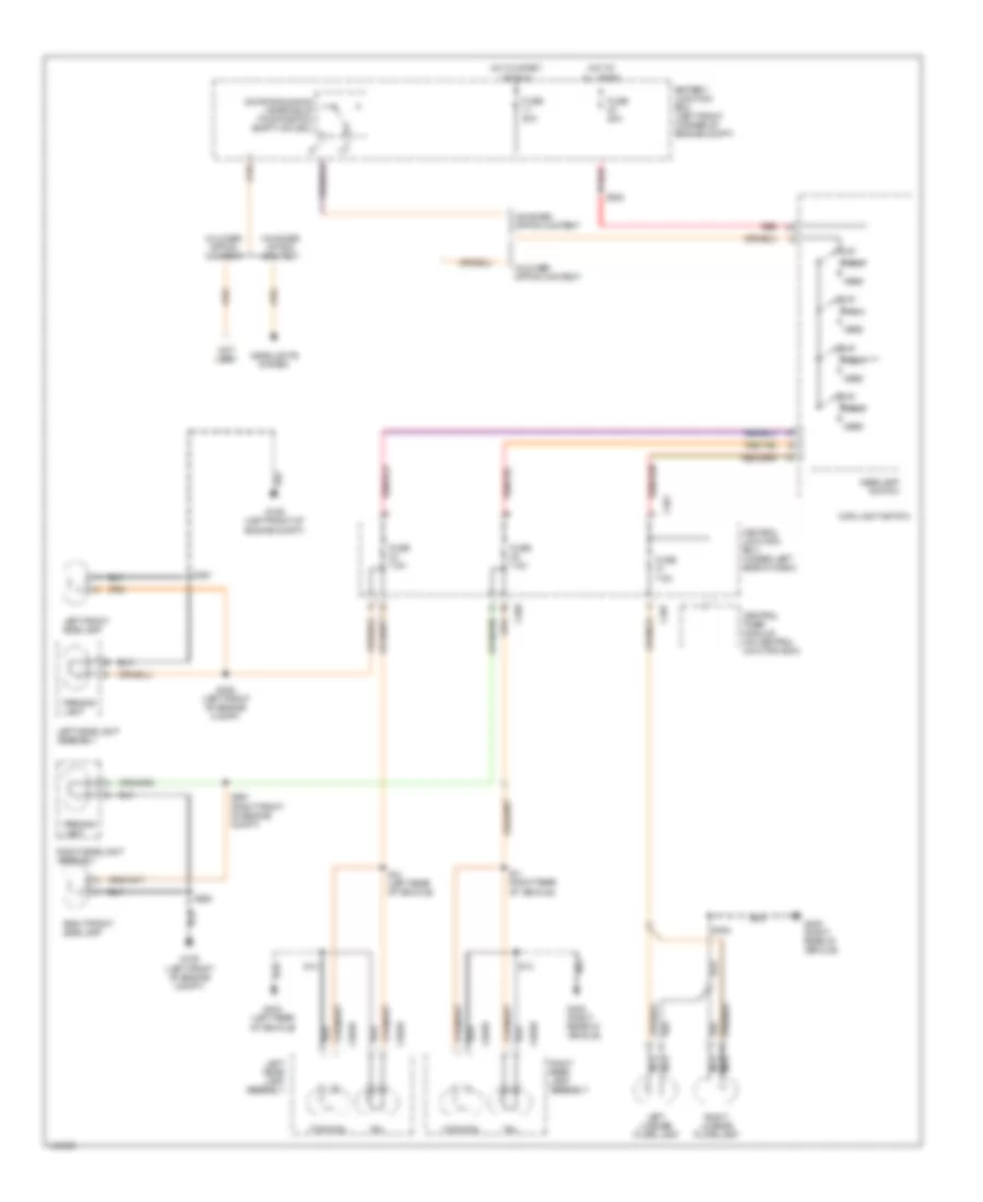
Headlight Wiring Diagram, without DRL for Mercury Cougar S 2001
List of elements for Headlight Wiring Diagram, without DRL for Mercury Cougar S 2001:
- (left front of engine compt) g106
- (not used)
- Battery junction box
- C320
- C361
- C459
- C808a
- C808b
- Central junction box
- Dimmer switch
- Flash-to- pass switch
- Fog lamp relay (behind left side of dash)
- Fog lamps ind
- Fog lamps switch
- Fuse 20a
- Fuse 26 7.5a
- Fuse 7.5a
- G100 (left front of engine compt)
- G106 (left front of engine compt)
- G110 (left front of engine)
- G203 (right kick panel)
- Head
- Hi beam headlamp relay
- Hi beam ind
- Hot at all times
- Instrument cluster
- Left fog lamp
- Left headlamp
- Liftgate/ decklid release switch
- Light switch
- Lo beam headlamp relay
- Multifunction switch
- Neutral
- Off
- Park
- Pass
- Red
- Right fog lamp
- Right headlamp
- S345 (front center engine compt)
- S346 (front center engine compt)
- S347 (front center engine compt)
- S348 (front center engine compt)
- S359
- S361
- S362
- S363
- S405 (left side of firewall)
- S422
- S423
HORN
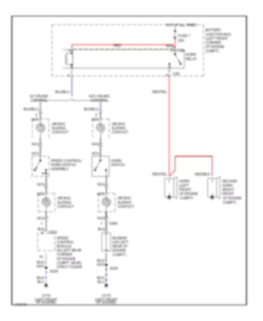
Horn Wiring Diagram for Mercury Cougar S 2001
List of elements for Horn Wiring Diagram for Mercury Cougar S 2001:
- 20a
- Air bag sliding contact
- Battery junction box (left front corner of engine compt)
- Busbar (on left rear of engine compt)
- C69
- C69 horn relay
- C833
- C896
- Fuse 7
- G110 (left front of engine)
- Horn (left front of engine compt)
- Horn switch
- Hot at all times
- Nca
- Red
- S250
- Second horn (right front of engine compt)
- Speed control module (in left rear corner of engine compt, near) strut tower
- Speed control/ horn switch assembly
- W/ cruise control
- W/o cruise control
INSTRUMENT CLUSTER
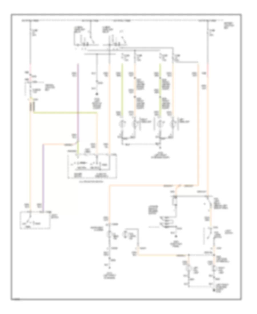
Instrument Cluster Wiring Diagram (1 of 2) for Mercury Cougar S 2001
List of elements for Instrument Cluster Wiring Diagram (1 of 2) for Mercury Cougar S 2001:
- (2 bulbs)
- (2001 only)
- (3 bulbs)
- (a/t)
- (left front of engine) g110
- (not used)
- 15-ge42
- 15-gg14
- 15s-ba9
- 2.0l
- 2.5l
- 29-gg14
- 29s-ld13
- 29s-ld7
- 29s-le11
- 29s-lg18
- 31s-cf28
- 31s-cf45
- 31s-gc10
- 31s-gc21
- 31s-gc6
- 31s-ge11
- 31s-ge13
- 31s-ge18
- 31s-ge49
- 31s-ge54
- 31s-ge7
- 31s-ge7b
- 31s-ge9
- 31s-pg11
- 49-lg15
- 49-lg22
- 64s-lk29
- 75-gg14
- 8-gb8
- 8-gc8
- 8-gc9
- 8-ge38
- 8-gg10
- 8-gg14
- 8-gg18
- 8-gg7
- 8-gg8
- 8-gg9
- 8-gh11
- 8-gh6
- 9-ge38
- 91-ga7
- 91-ge42
- 91s-ja14
- 91s-rd7
- 91s-ta29
- A10
- A11
- A14
- A15
- A16
- A17
- A18
- A19
- A20
- A21
- A22
- A23
- A25
- Abs ind
- Air bag ind
- Anti-lock brakes system
- Anti-theft system
- B10
- B11
- B12
- B13
- B14
- B15
- B16
- B17
- B18
- B19
- B20
- B21
- B22
- B23
- B25
- B26
- Board computer
- C808a
- C808b
- Charge ind
- Check engine ind
- Clock
- Clock/ odometer
- Computer data lines system
- Coolant temperature sensor (on left rear of engine)
- Coolant temperature sensor (on right rear of engine)
- Cruise control system
- Display assembly, auxiliary warning system
- Engine controls system
- Engine coolant
- Exterior lights system
- Foglights ind
- Fuel gauge
- Fuel tank unit
- G106 (left front of engine compt)
- G110 (left front of engine)
- Ga-15
- Ga7a
- Gb10
- Gg14a
- Gg14b
- Headlights system
- Headlights system engine controls system anti-theft system
- Hi beam ind
- Illumination
- Instrument cluster
- Interior lights system
- Left turn ind
- Lights on ind
- Low brake fluid level/ park brake ind
- Low cleaning water level switch
- Low coolant level ind
- Low coolant level switch (in right front corner of engine compt)
- Low fuel ind
- Low oil pressure ind
- Re22a
- Rear foglights ind
- Reset
- Right turn ind
- S359
- S361
- S362
- S62
- Seat belt ind
- Select
- Sound system
- Speed ctrl ind
- Speedometer
- Starting/charging system
- Tachometer
- Traction control ind
- Trip computer switch
- Units
- Warning system
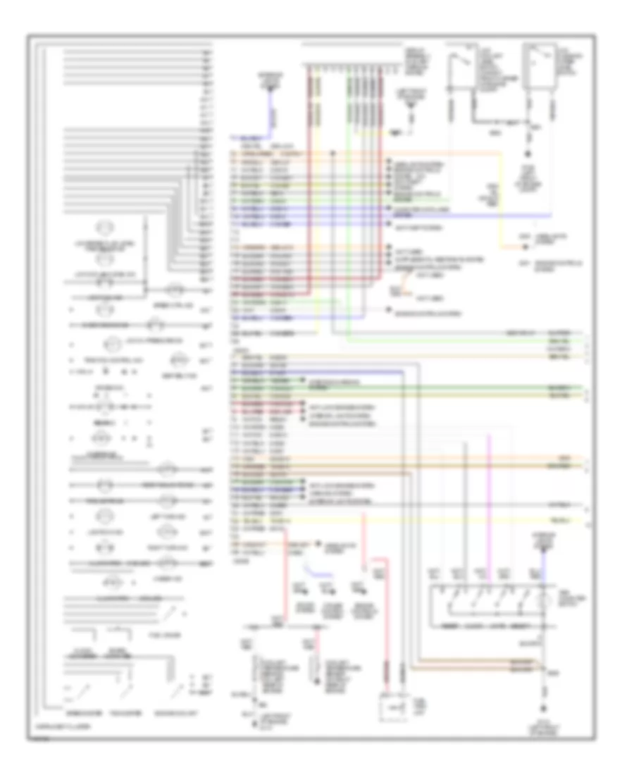
Instrument Cluster Wiring Diagram (2 of 2) for Mercury Cougar S 2001
List of elements for Instrument Cluster Wiring Diagram (2 of 2) for Mercury Cougar S 2001:
- (2000)
- (2001)
- (a/t)
- 15-gg15
- 15s-gg15
- 15s-re13
- 15s-ta21
- 29s-gg20
- 31s-pg11
- 31s-ta33
- 8-gh11
- 8-pg11
- 91-gg15
- Acc
- Anti-lock brakes system
- Brake fluid level switch (in left rear of engine compt)
- Brake pedal position switch
- C360
- C361
- C362
- C365
- C366
- C369
- C421
- Central junction box
- Cruise control system
- Fuse 23 15a
- Fuse 24 15a
- Fuse 25 20a
- Fuse 30 7.5a
- Fuse 34 7.5a
- G106 (left front of engine compt)
- G110 (left front of engine)
- G203 (right kick panel)
- Gearshift lever unit (under center console)
- Hot at all times
- Hot in run or start
- Ice warning sensor (on front center of engine compt)
- Ignition switch
- Instrument interface module (behind left side of dash)
- Interior lights system
- Key removal inhibit solenoid (top of steering column)
- Lock
- Nca
- O/d switch
- Oil pressure switch (2.0l: on right side of engine, 2.5l: on left side of engine)
- Park brake switch (at base of parking brake lever)
- Power distribution system
- Powertrain control module (in right rear corner of engine compt, behind power steering reservoir)
- Run
- S106 (behind left side of dash)
- S130 (behind left side of dash)
- S359
- S363
- S367 (behind left side of dash)
- Start
- Stoplight switch (on bracket, above brake pedal)
INTERIOR LIGHTS
Courtesy Lamps Wiring Diagram, High Option Content for Mercury Cougar S 2001
List of elements for Courtesy Lamps Wiring Diagram, High Option Content for Mercury Cougar S 2001:
- 31sgl46
- 31sgl47
- 8aa36
- Anti-theft system
- Anti-theft/ central locking module (on center of right "a" pillar)
- Battery junction box (left front corner of engine compt)
- C23
- C361
- C364
- C366
- C367
- C370
- C451a
- C451b
- C808a
- C890a
- C890b
- Central junction box (under left side of dash)
- Central timer module
- Courtesy lamp relay
- Door
- Front interior lamp
- Fuse 31 7.5a
- Fuse 34 7.5a
- Fuse 52 60a
- G203 (right kick panel)
- G404 (left rear of vehicle)
- G405 (right rear of vehicle)
- Glove box lamp
- Glove box lamp switch
- Hot at all times
- Hot in park or head
- Instrument cluster
- Left front door courtesy lamp switch
- Left vanity mirror
- Liftgate/ decklid switch (center rear of vehicle)
- Luggage compartment lamp
- Nca
- Red
- Right front door courtesy lamp switch
- Right vanity mirror
- S17
- S241
- S34
- S354
- S355
- S36
- S423
Courtesy Lamps Wiring Diagram, Low Option Content for Mercury Cougar S 2001
List of elements for Courtesy Lamps Wiring Diagram, Low Option Content for Mercury Cougar S 2001:
- 31sgl46
- 31sgl47
- 8aa36
- Anti- theft system
- Anti-theft system
- Anti-theft/ central locking module (on center of right 'a' pillar)
- Battery junction box (left front corner of engine compt)
- C23
- C361
- C364
- C366
- C367
- C370
- C451a
- C451b
- C890a
- C890b
- Central junction box (under left side of dash)
- Central timer module
- Courtesy lamp relay
- Door
- Front interior lamp
- Fuse 31 7.5a
- Fuse 34 7.5a
- Fuse 52 60a
- G203 (right kick panel)
- G404 (left rear of vehicle)
- G405 (right rear of vehicle)
- Glove box lamp
- Glove box lamp switch
- Hot at all times
- Hot in park or head
- Left front door courtesy lamp switch
- Left vanity mirror
- Liftgate/ decklid switch (center rear of vehicle)
- Luggage compartment lamp
- Nca
- Red
- Right front door courtesy lamp switch
- Right vanity mirror
- S17
- S241
- S34
- S354
- S355
- S36
- S423
Instrument Illumination Wiring Diagram, High Option Content for Mercury Cougar S 2001
List of elements for Instrument Illumination Wiring Diagram, High Option Content for Mercury Cougar S 2001:
- (2 bulbs)
- (right kick panel) g203
- Battery junction box
- Bulbs)
- C361
- C367
- C443b
- C500b
- C808b
- Central junction box
- Driver door lock/unlock switch
- Driver power window switch
- Driver side passenger window operating switch
- Front cigar lighter
- Fuse 21 40a
- Fuse 26 7.5a
- Fuse 31 7.5a
- Fuse 40 20a
- G110 (left front of engine compt)
- G200 (left kick panel)
- G203 (right kick panel)
- Gearshift lever unit
- Head
- Headlamp switch panel illumination
- Heater panel illumination lamp
- Hot at all times
- Hot in run or start
- Illumination dimmer
- Instrument cluster
- Light switch
- Lower option content higher option content
- Nca
- Off
- Park
- Passenger door lock/ unlock switch
- Passenger side window operating switch
- Radio
- Rear window defrost switch
- Red
- S164
- S257
- S258
- S350 (in passenger door)
- S359
- S369 (behind center of dash)
- S422
- S423
- S86 (in driver door)
- Tailgate/decklid release switch
- Traction control system disable switch
- Trip computer switch
Instrument Illumination Wiring Diagram, Low Option Content for Mercury Cougar S 2001
List of elements for Instrument Illumination Wiring Diagram, Low Option Content for Mercury Cougar S 2001:
- (2 bulbs)
- (right kick panel) g203
- Battery junction box
- Bulbs)
- C361
- C367
- C443b
- C500b
- C808b
- Central junction box
- Driver door lock/unlock switch
- Driver power window switch
- Driver side passenger window operating switch
- Front cigar lighter
- Fuse 21 40a
- Fuse 26 7.5a
- Fuse 31 7.5a
- Fuse 40 20a
- G110 (left front of engine compt)
- G200 (left kick panel)
- G203 (right kick panel)
- Gearshift lever unit
- Head
- Headlamp switch panel illumination
- Heater panel illumination lamp
- Hot at all times
- Hot in run or start
- Illumination dimmer
- Instrument cluster
- Light switch
- Lower option content higher option content
- Nca
- Off
- Park
- Passenger door lock/ unlock switch
- Passenger side window operating switch
- Radio
- Rear window defrost switch
- Red
- S164
- S257
- S258
- S350 (in passenger door)
- S358
- S359
- S369 (behind center of dash)
- S422
- S423
- S86 (in driver door)
- Tailgate/decklid release switch
- Trip computer switch
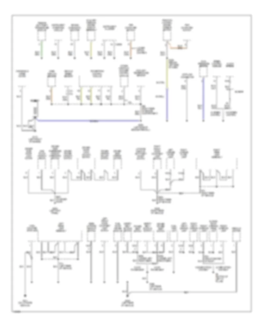
POWER DISTRIBUTION
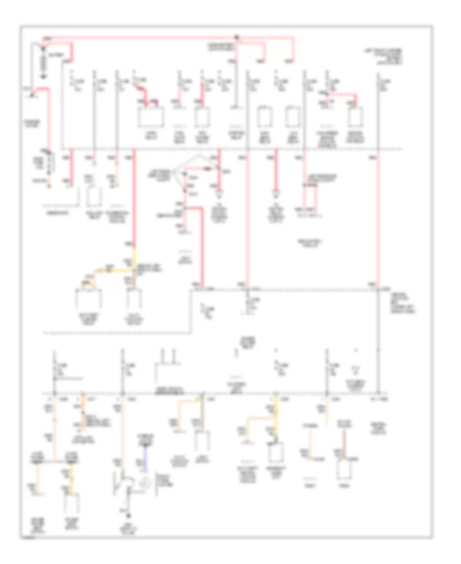
Power Distribution Wiring Diagram (1 of 4) for Mercury Cougar S 2001
List of elements for Power Distribution Wiring Diagram (1 of 4) for Mercury Cougar S 2001:
- (behind left side of dash) s10
- (left front corner of eng compt) battery junction box
- (left rear side of eng compt)
- (near battery junction box)
- 2-way power seat
- 8-way power seat
- Abs control module
- Anti-theft flasher relay
- Anti-theft/ central locking module
- Battery
- C23
- C360
- C361
- C363
- C364
- C366
- C370
- C371
- C443b
- C500b
- Central junction box (under left side of dash)
- Central timer module
- Courtesy lamp relay
- Data link connector
- Dm 100i & cdx6
- Driver power seat switch
- Engine cooling fan relay
- Fog lamp relay
- Front cigar lighter
- Fuel pump relay
- Fuse 15a
- Fuse 20a
- Fuse 30a
- Fuse 3a
- Fuse 40a
- Fuse 60a
- Fuse 7.5a
- G901 (right "a" pillar)
- Gearshift lever unit
- Generator
- Heater blower relay
- High beam relay
- High speed engine cooling fan relay
- Horn relay
- Interior lights system
- Light switch
- Low beam relay
- Mega fuse 175a
- Multi- function switch
- Nca
- Others
- Pcm power relay
- Power seat switch
- Powertrain control module
- Radio
- Rear window defrost relay
- Red
- S1002
- S232
- S233
- S3010 (behind left side of dash)
- S310
- S422 (behind dash)
- Starter motor
- Starter relay
- To fuse 34 (diagram 3 of 4)
- To ignition relay (diagram 2 of 4)
- To ignition switch (diagram 2 of 4)
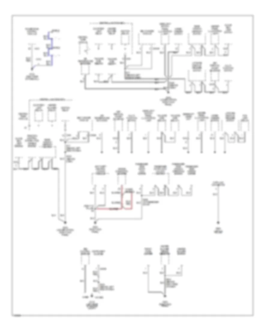
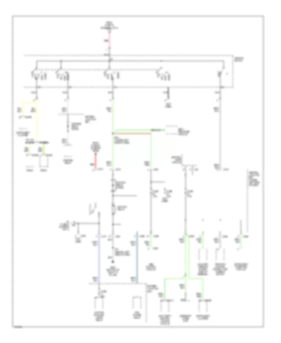
Power Distribution Wiring Diagram (2 of 4) for Mercury Cougar S 2001
List of elements for Power Distribution Wiring Diagram (2 of 4) for Mercury Cougar S 2001:
- (not used
- (not used)
- Abs control module
- Acc
- Anti-theft/ central locking module
- Auxiliary warning system display assembly
- Battery junction box
- Belt reminder module
- C23
- C361
- C362
- C363
- C365
- C366
- C369
- C370
- C371
- C372
- C385
- C443b
- C451a
- C500b
- C808b
- Central junction box (under left side of dash)
- Central timer module
- Daytime running lamps relay
- Dm 100i & cdx6
- From fuse 40 (diagram 1 of 4)
- From fuse 45 (diagram 1 of 4)
- Fuse 20a
- Fuse 7.5a
- G203 (bottom of right "a" pillar)
- Gearshift lever unit
- Ignition relay
- Ignition relay diode
- Ignition switch
- Instrument cluster
- Instrument interface module
- Lock
- Nca
- Off
- Others
- Pcm power relay
- Radio
- Red
- Run
- S17 (behind left side of dash)
- S341 (under left side of dash)
- Start
- Starter relay
- Starter relay diode
- To fuse 20 (diagram 4 of 4)
- Traction control system (tcs) disable switch
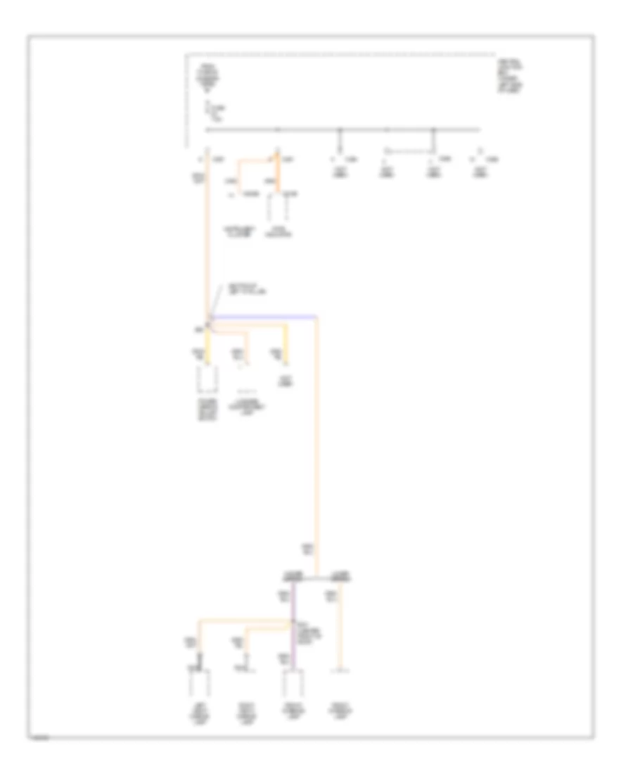
Power Distribution Wiring Diagram (3 of 4) for Mercury Cougar S 2001
List of elements for Power Distribution Wiring Diagram (3 of 4) for Mercury Cougar S 2001:
- (bottom of left "a" pillar)
- (not used)
- C2106
- C361
- C364
- C365
- C366
- C367
- C808b
- Central junction box (under left side of dash)
- From fuse 36 (diagram 1 of 4)
- Front interior lamp
- Fuse 7.5a
- Higher option
- Instrument cluster
- Left vanity mirror lamp
- Lower option
- Luggage compartment lamp
- Nca
- Pats indicator
- Power mirror adjust switch
- Right vanity mirror lamp
- S241 (center front of roof)
- S36
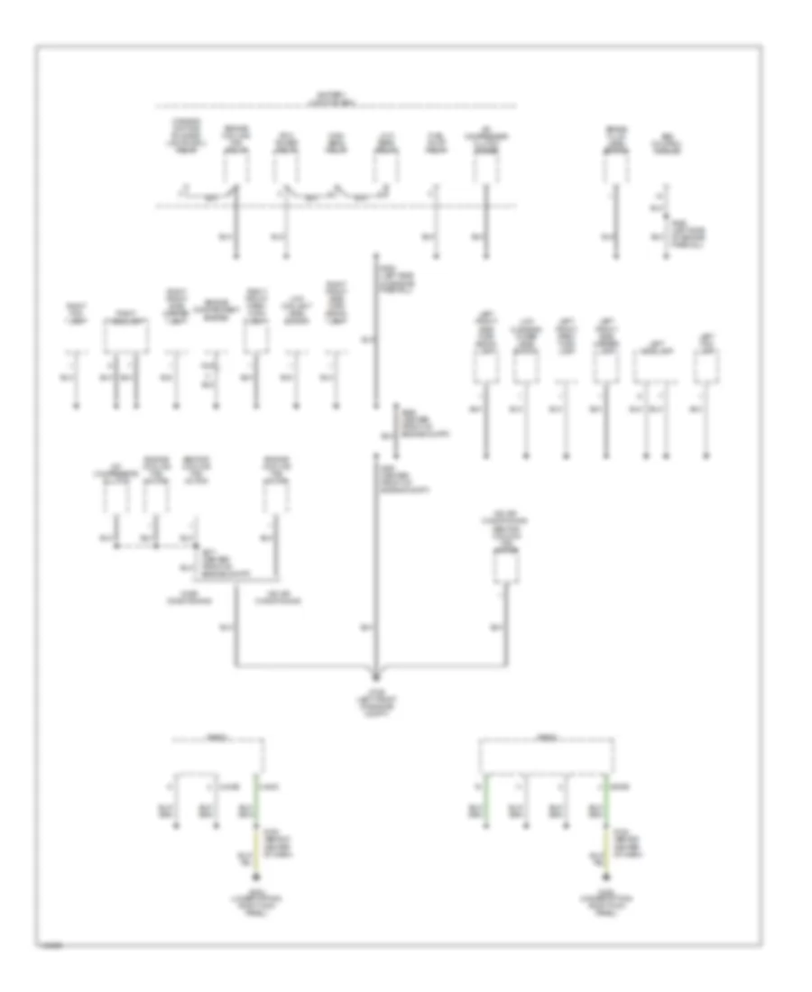
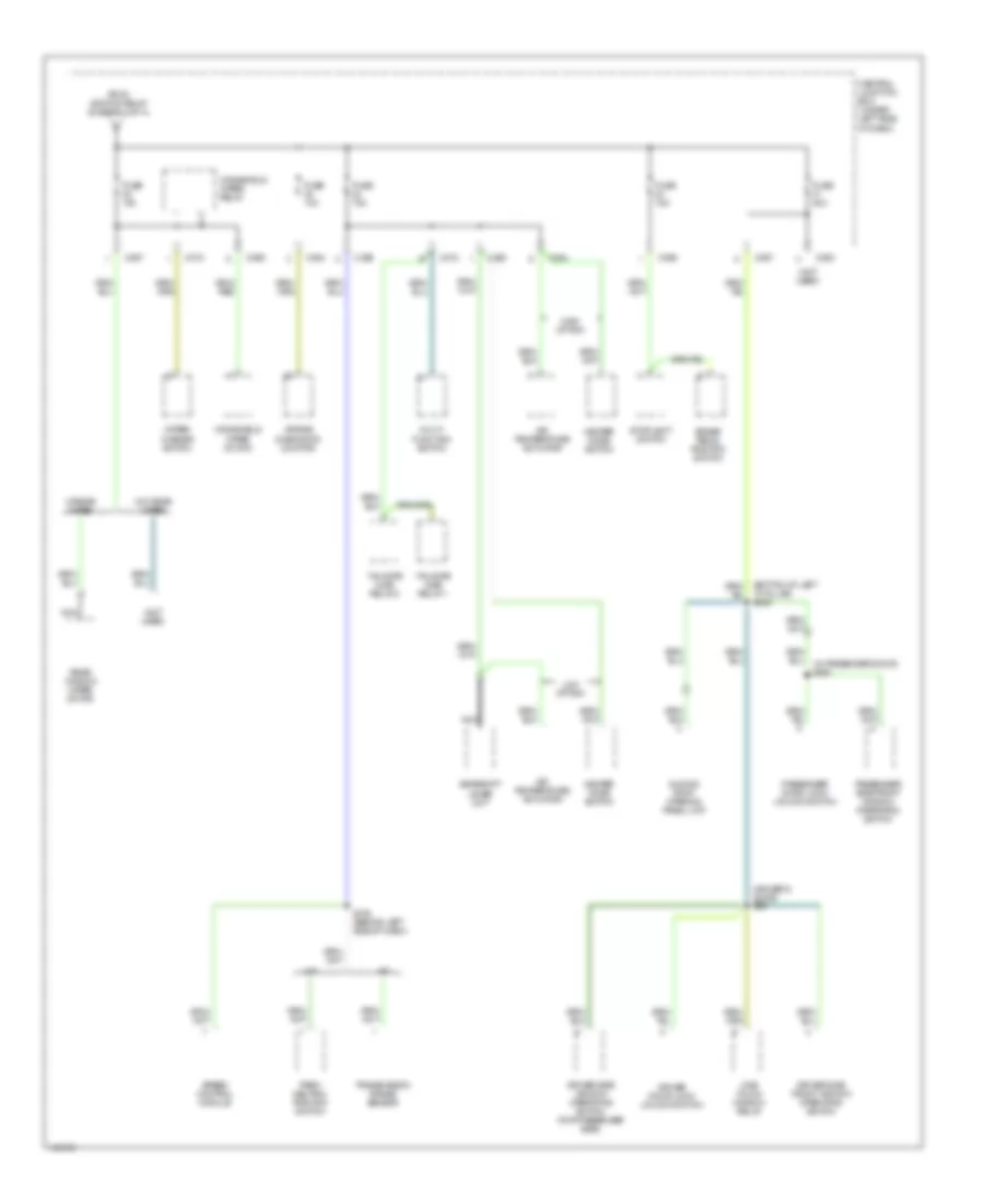
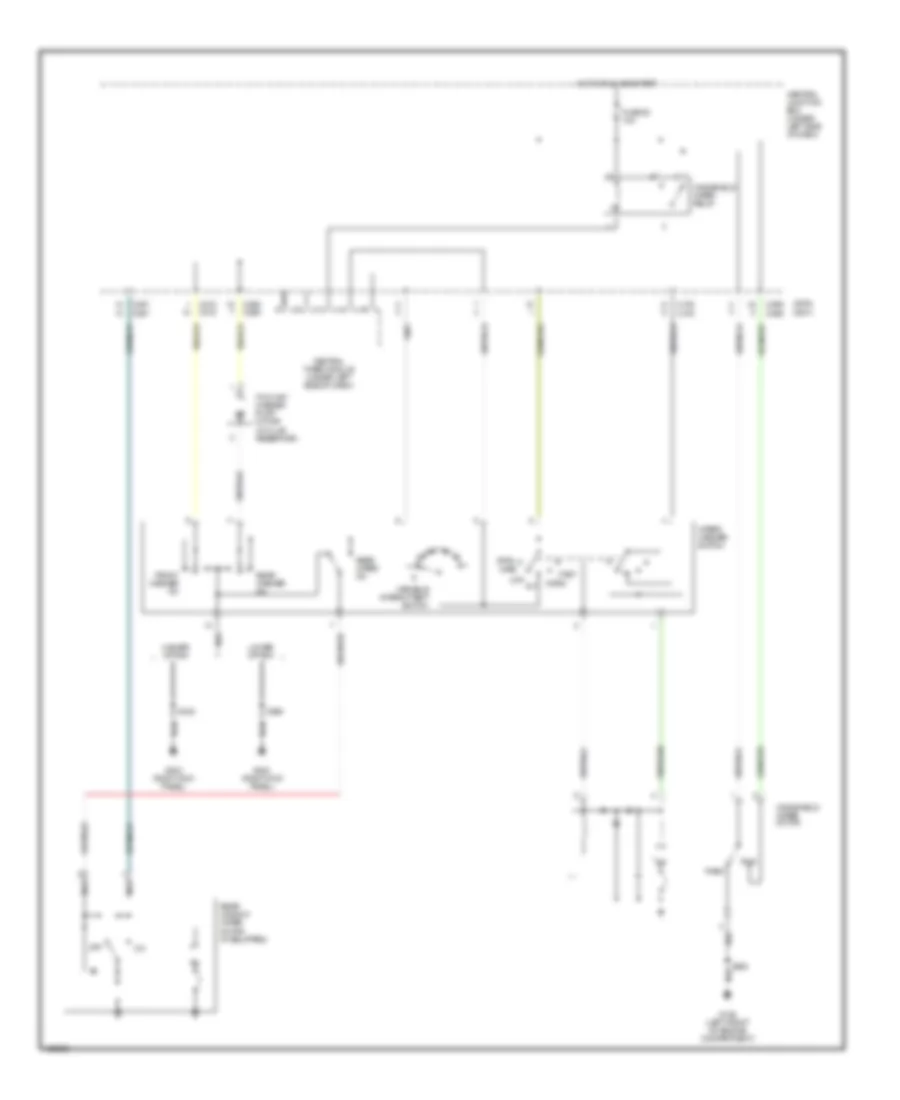
Power Distribution Wiring Diagram (4 of 4) for Mercury Cougar S 2001
List of elements for Power Distribution Wiring Diagram (4 of 4) for Mercury Cougar S 2001:
- "a" pillar) s349
- (driver's door) s86
- (in passenger door) s350
- (not used)
- A/t
- Air bag diagnostic monitor
- Air temperature actuator
- Brake pedal position switch
- C360
- C363
- C364
- C367
- C369
- C372
- Central junction box (under left side of dash)
- Driver door lock/ unlock switch
- Driver side front window operating switch
- Driver side window operating switch (for passenger side)
- From ignition relay (diagram 2 of 4)
- Fuse 10a
- Fuse 15a
- Fuse 40a
- Gearshift lever unit
- Heater mode switch
- High option
- Low option
- M/t
- Multi- function switch
- Nca
- One touch window relay
- Park/ neutral position switch
- Passenger door lock/ unlock switch
- Passenger side front window operating switch
- Rear window wiper motor
- S136 (behind left side of dash)
- Sliding roof opening panel unit
- Speed control module
- Stoplight switch
- Tailgate ajar relay 1
- Tailgate ajar relay 2
- Transmission range sensor
- W/o rear wiper
- W/rear wiper
- Windshield wiper motor
- Windshield wiper relay
- Wiper/ washer switch
POWER DOOR LOCKS
Power Door Lock Wiring Diagram (1 of 2) for Mercury Cougar S 2001
List of elements for Power Door Lock Wiring Diagram (1 of 2) for Mercury Cougar S 2001:
- (right 'a' pillar) s6
- (right rear corner of engine compt) powertrain control module
- (w/ remote control
- 14-aa17
- 2.0l
- 2.5l
- 29-aa17
- 29s-aa27
- 31-aa17
- 31-aa57
- 31s-aa30
- 31s-aa61
- 31s-aa61a
- 31s-aa62
- 31s-aa62a
- 31s-aa63
- 31s-aa63a
- 31s-aa64
- 31s-aa64a
- 31s-gl15
- 31s-gl20
- 31s-gl24
- 31s-gl27
- 31s-gl46
- 31s-gl47
- 31s-gl6
- 31s-gl7
- 32-aa34
- 32-aa65
- 32-aa66
- 33-aa34
- 33-aa59
- 33-aa60
- 49-gl26
- 8-aa36
- 8-aa6
- Anti-theft horn (right side luggage compt)
- Anti-theft/ central locking module (on center of right 'a' pillar)
- C23
- C360
- C361
- C362
- C366
- C421
- C443b
- C451a
- C451b
- Central junction box (under left side of dash)
- Central locking)
- Central timer module
- Data link connector (under center of dash)
- Driver door lock/ unlock switch
- Fuse 25 20a
- Fuse 30 7.5a
- Fuse 34 7.5a
- G200 (left kick panel)
- G203 (right kick panel)
- G405 (right rear of vehicle)
- Hot at all times
- Hot in run or start
- Interior lights system
- Lock
- Passenger door lock/unlock switch
- Pats indicator
- Radio
- S257
- S258
- S354
- S7 (right 'a' pillar)
- Tailgate/ decklid anti-theft inhibit switch (right rear of vehicle)
- Trunk/tailgate fuel door release system
- Unlk
Power Door Lock Wiring Diagram (2 of 2) for Mercury Cougar S 2001
List of elements for Power Door Lock Wiring Diagram (2 of 2) for Mercury Cougar S 2001:
- (left front of engine compt) g106
- (right "a" pillar)
- (right kick panel) g203
- (w/ remote control
- 31s-ge11
- 31s-ge7
- 31s-ge9
- Anti-theft flasher relay (on base of right "a" pillar)
- Battery junction box (left front corner of engine compt)
- C23
- C366
- C372
- C808a
- Central junction box (under left side of dash)
- Central locking)
- Central timer module (under left side of dash, on central junction box)
- Driver side door lock motor
- Engine compartment switch (left front of engine compt)
- Exterior lights system
- Fuse 23 15a
- Fuse 7 20a
- G200 (left kick panel)
- G203 (right kick panel)
- G404 (left rear of vehicle)
- G405 (right rear of vehicle)
- High option content
- Hot at all times
- Hot in run or start
- Instrument cluster
- Interior lights system
- Left front door courtesy lamp switch
- Liftgate/ decklid switch (center rear of vehicle)
- Low option content
- Nca
- Passenger side door lock motor
- Right front door courtesy lamp switch
- S257
- S258
- S354
- S355
- S362
- S370 (right "a" pillar)
- S371
- S423
- Tailgate ajar relay 1 (behind right side of dash)
- Tailgate ajar relay 2 (behind right side of dash)
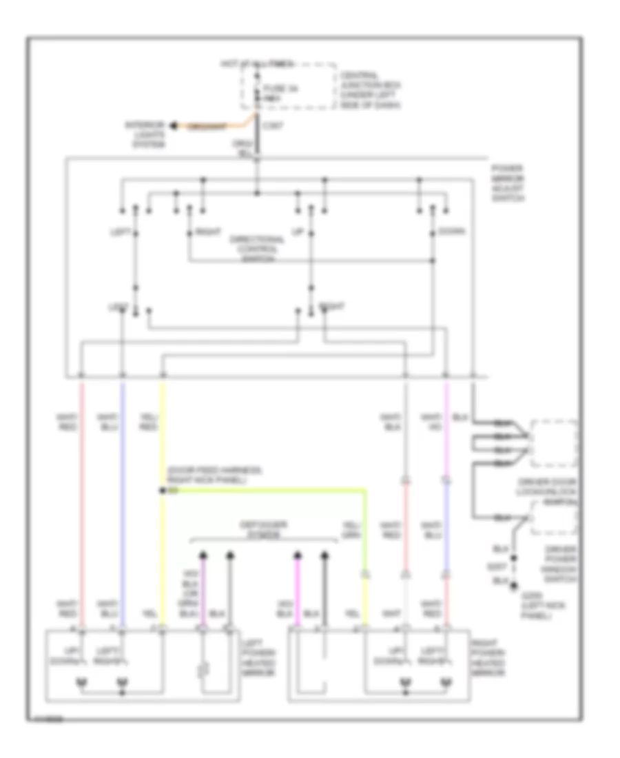
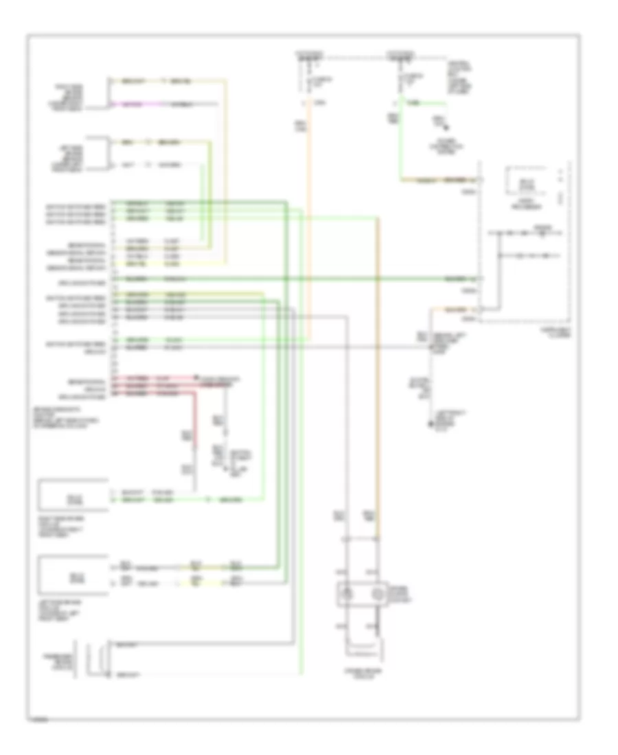
POWER MIRRORS
Power Mirror Wiring Diagram for Mercury Cougar S 2001
List of elements for Power Mirror Wiring Diagram for Mercury Cougar S 2001:
- (door feed harness, right kick panel) s3
- C367
- Central junction box (under left side of dash)
- Defogger system
- Directional control switch
- Down
- Driver door lock/unlock switch
- Driver power window switch
- Fuse 34 7.5a
- G200 (left kick panel)
- Hot at all times
- Interior lights system
- Left
- Left power/ heated mirror
- Left/ right
- Power mirror adjust switch
- Right
- Right power/ heated mirror
- S257
- Up/ down
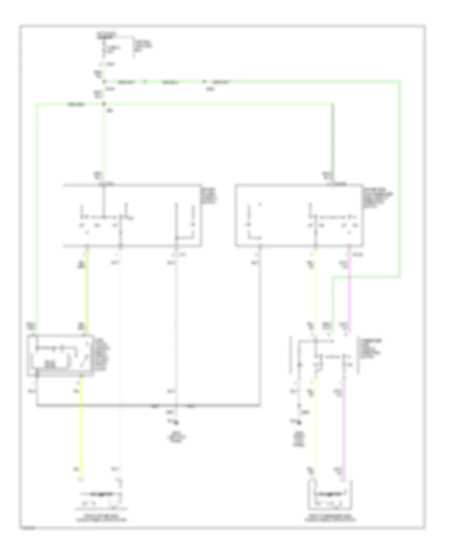
POWER SEATS
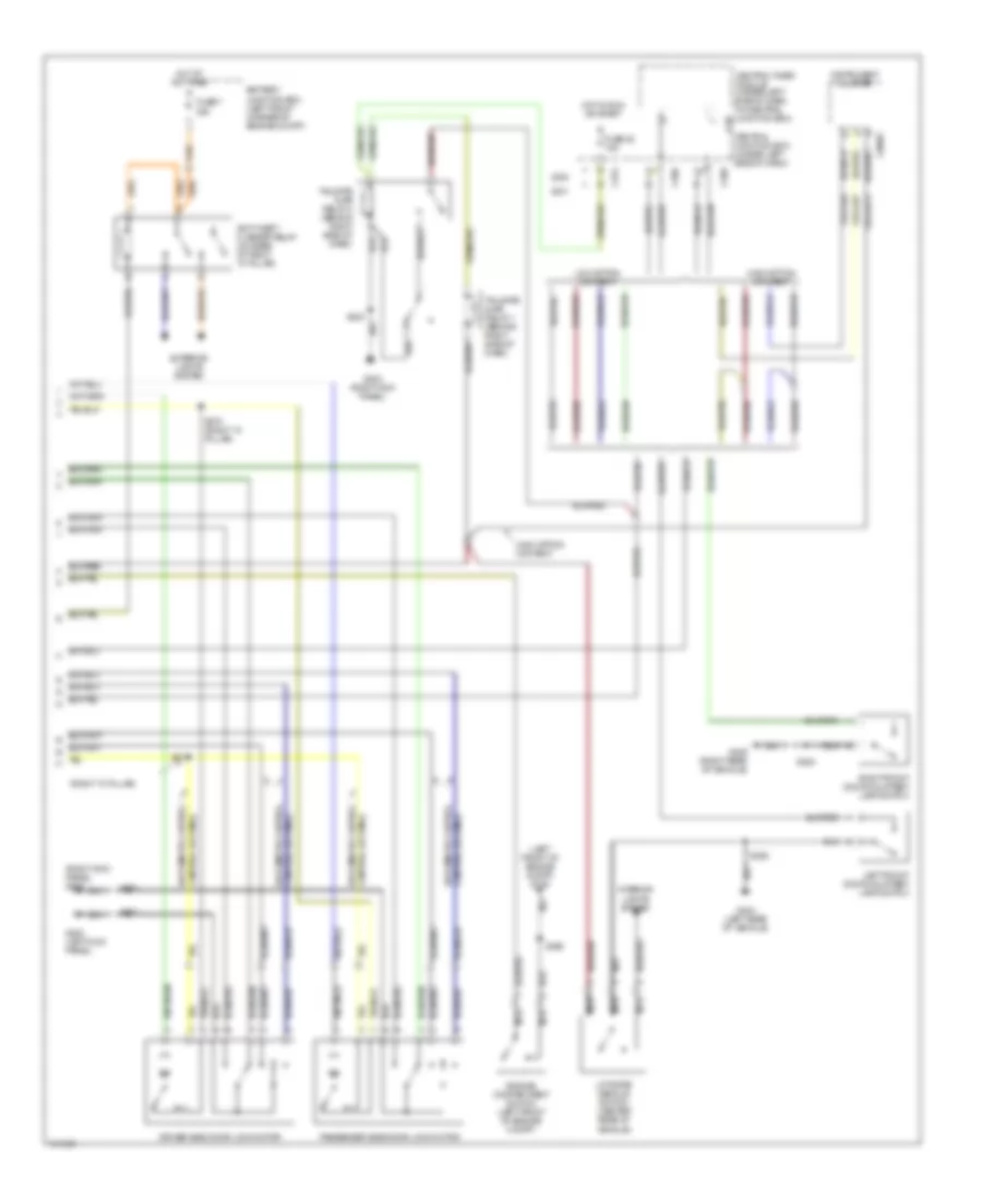
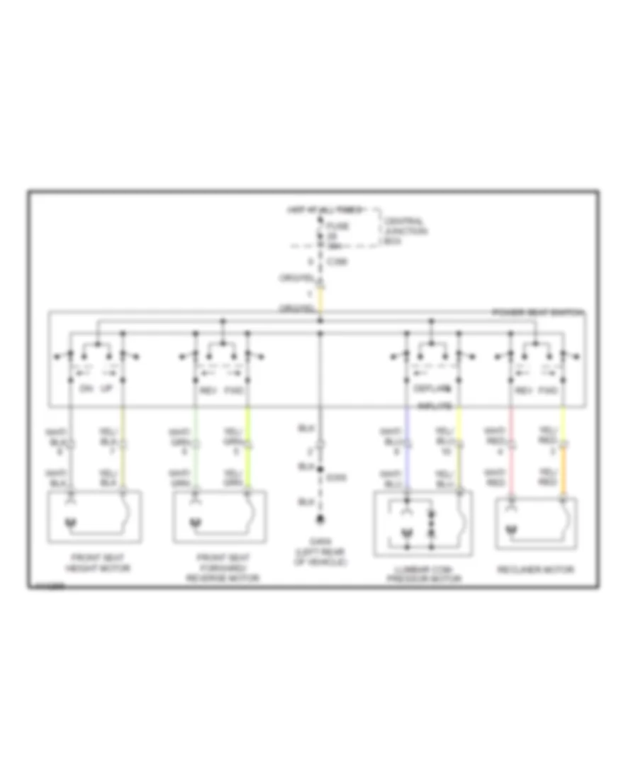
8-Way Adjustable Power Seat Wiring Diagram for Mercury Cougar S 2001
List of elements for 8-Way Adjustable Power Seat Wiring Diagram for Mercury Cougar S 2001:
- C366
- Central junction box
- Deflate
- Front seat forward/ reverse motor
- Front seat height motor
- Fuse 30a
- Fwd
- G404 (left rear of vehicle)
- Hot at all times
- Inflate
- Lumbar com- pressor motor
- Power seat switch
- Recliner motor
- Rev
- S356
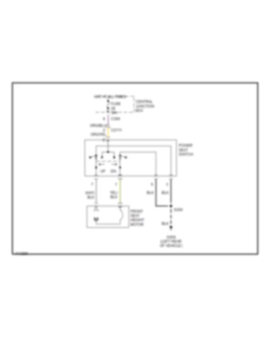
Seat Height Adjuster Wiring Diagram for Mercury Cougar S 2001
List of elements for Seat Height Adjuster Wiring Diagram for Mercury Cougar S 2001:
- C2111
- C366
- Central junction box
- Front seat height motor
- Fuse 30a
- G404 (left rear of vehicle)
- Hot at all times
- Power seat switch
- S356
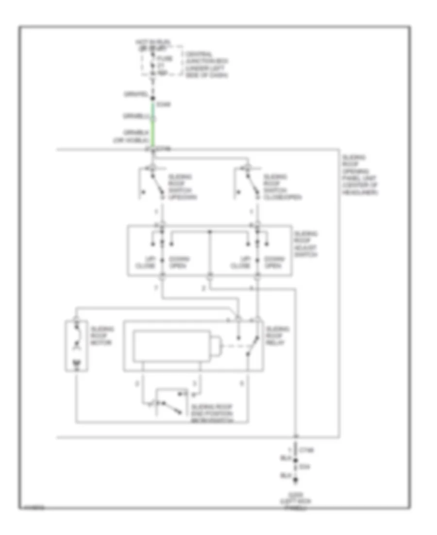
POWER TOP/SUNROOF
Power Top/Sunroof Wiring Diagrams for Mercury Cougar S 2001
List of elements for Power Top/Sunroof Wiring Diagrams for Mercury Cougar S 2001:
- C748
- Central junction box (under left side of dash)
- Down/ open
- Fuse 40a
- G200 (left kick panel)
- Hot in run or start
- S34
- S349
- Sliding roof adjust switch
- Sliding roof end position microswitch
- Sliding roof motor
- Sliding roof opening panel unit (center of headliner)
- Sliding roof relay
- Sliding roof switch close/open
- Sliding roof switch up/down
- Up/ close
POWER WINDOWS
Power Window Wiring Diagram for Mercury Cougar S 2001
List of elements for Power Window Wiring Diagram for Mercury Cougar S 2001:
- C2125
- C367
- C74
- Central junction box
- Driver power window switch
- Driver side for passenger side window operating switch
- Front driver side window regulating motor
- Front passenger side window regulating motor
- Fuse 21 40a
- G200 (left kick panel)
- G203 (right kick panel)
- Hot in run or start
- One- touch window relay (front of left front door)
- Passenger side window operating switch
- S257
- S258
- S349
- S350
- S86
- Solid state
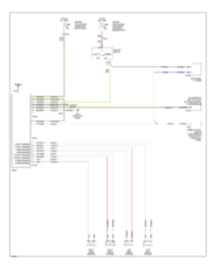
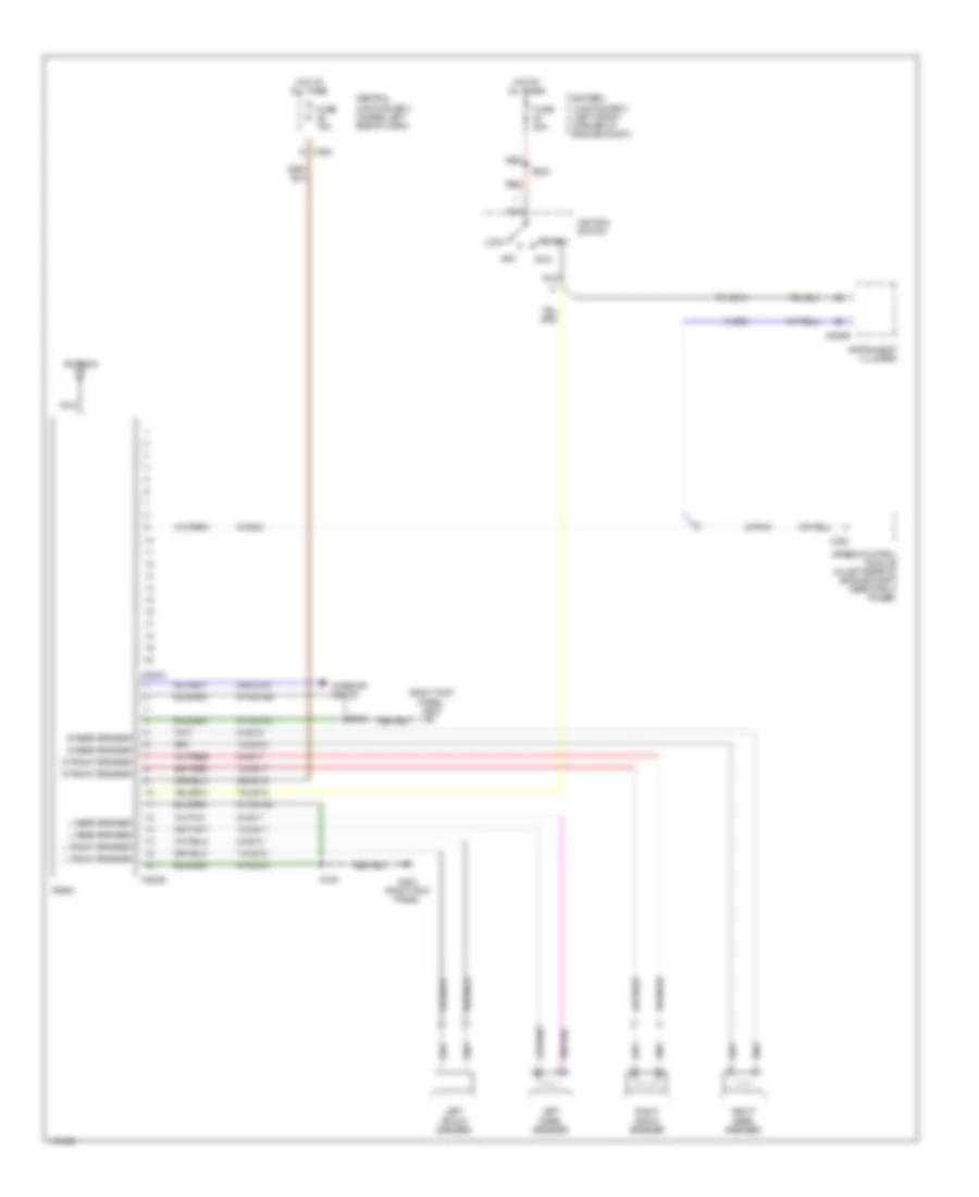
RADIO
Radio Wiring Diagrams, High Option Content for Mercury Cougar S 2001
List of elements for Radio Wiring Diagrams, High Option Content for Mercury Cougar S 2001:
- (on center of right "a" pillar) anti-theft/central locking module
- 10-md10
- 10-md11
- 10-md17
- 10-md18
- 29-md15
- 31s-gl15
- 64s-lk34
- 75-gg14
- 75-md15
- 8-gb8
- 8-md10
- 8-md11
- 8-md17
- 8-md18
- 8-md24
- 8-pg18
- 91-md15
- 91-md15a
- 91-md15b
- Acc
- Antenna
- Battery junction box (left front corner of engine compt)
- C364
- C443a
- C443b
- C443c
- C451b
- C808b
- C833
- Central junction box (under left side of dash)
- Fuse 15a
- Fuse 20a
- G203 (right kick panel)
- Hot at all times
- Ignition switch
- Instrument cluster
- Interior lights
- L front speaker
- L rear speaker
- Left front speaker
- Left rear speaker
- Lock
- Nca
- R front speaker
- R rear speaker
- Radio
- Red
- Right front speaker
- Right rear speaker
- Run
- S164
- S232
- Speed control module (in left rear of engine compt near strut tower)
- Start
Radio Wiring Diagrams, Low Option Content for Mercury Cougar S 2001
List of elements for Radio Wiring Diagrams, Low Option Content for Mercury Cougar S 2001:
- (right kick panel) g203
- 10-md10
- 10-md11
- 10-md17
- 10-md18
- 29-md15
- 64s-lk34
- 75-gg14
- 75-md15
- 8-gb8
- 8-md10
- 8-md11
- 8-md17
- 8-md18
- 8-md24
- 8-pg18
- 91-md15
- 91-md15a
- 91-md15b
- 91-md15c
- Acc
- Antenna
- Battery junction box (left front corner of engine compt)
- C364
- C500a
- C500b
- C808b
- C833
- Central junction box (under left side of dash)
- Fuse 15a
- Fuse 20a
- G203 (right kick panel)
- Hot at all times
- Ignition switch
- Instrument cluster
- Interior lights
- L front speaker
- L rear speaker
- Left front speaker
- Left rear speaker
- Lock
- Nca
- R front speaker
- R rear speaker
- Radio
- Red
- Right front speaker
- Right rear speaker
- Run
- S164
- S232
- Speed control module (in left rear of engine compt near strut tower)
- Start
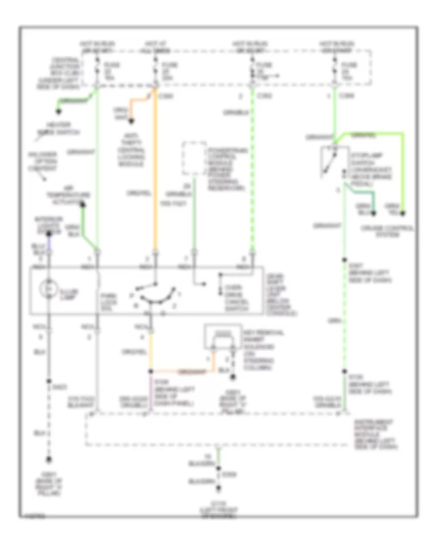
SHIFT INTERLOCKS
Shift Interlock Wiring Diagram for Mercury Cougar S 2001
List of elements for Shift Interlock Wiring Diagram for Mercury Cougar S 2001:
- 15s-ta21
- Air temperature actuator
- Anti- theft/ central locking module
- C360
- C362
- C369
- Central junction box (cjb) (under left side of dash)
- Cruise control system
- Dash panel)
- Fuse 15a
- Fuse 20a
- Fuse 7.5a
- G110 (left front of engine)
- G901 (base of right "a" pillar)
- Gear- shift lever unit (below center console)
- Heater mode switch
- Hot at all times
- Hot in run or start
- Illum. lamp
- Instrument interface module (behind left side of dash)
- Interior lights system
- Key removal inhibit solenoid (on steering column)
- Nca
- Over- drive cancel switch
- Park lock sol
- Powertrain control module (behind power steering reservoir)
- S130 (behind left side of dash)
- S359
- S367 (behind left side of dash)
- S423
- Stoplamp switch (on bracket, above brake pedal)
- W/lower option content
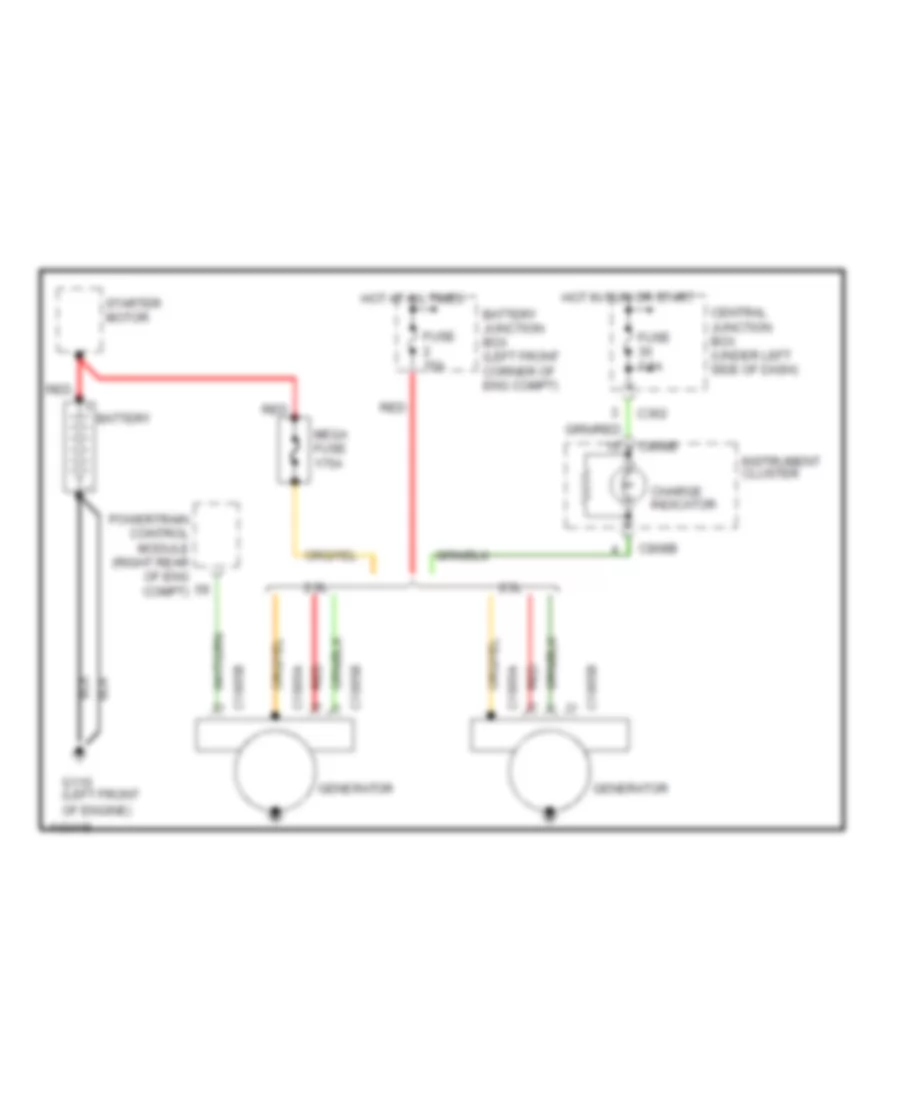
STARTING/CHARGING
Charging Wiring Diagram for Mercury Cougar S 2001
List of elements for Charging Wiring Diagram for Mercury Cougar S 2001:
- 2.0l
- 2.5l
- Battery
- Battery junction box (left front corner of eng compt)
- C1885a
- C1885b
- C362
- C808b
- Central junction box (under left side of dash)
- Charge indicator
- Fuse 15a
- Fuse 7.5a
- G110 (left front of engine)
- Generator
- Hot at all times
- Hot in run or start
- Instrument cluster
- Mega fuse 175a
- Powertrain control module (right rear of eng compt)
- Red
- Starter motor
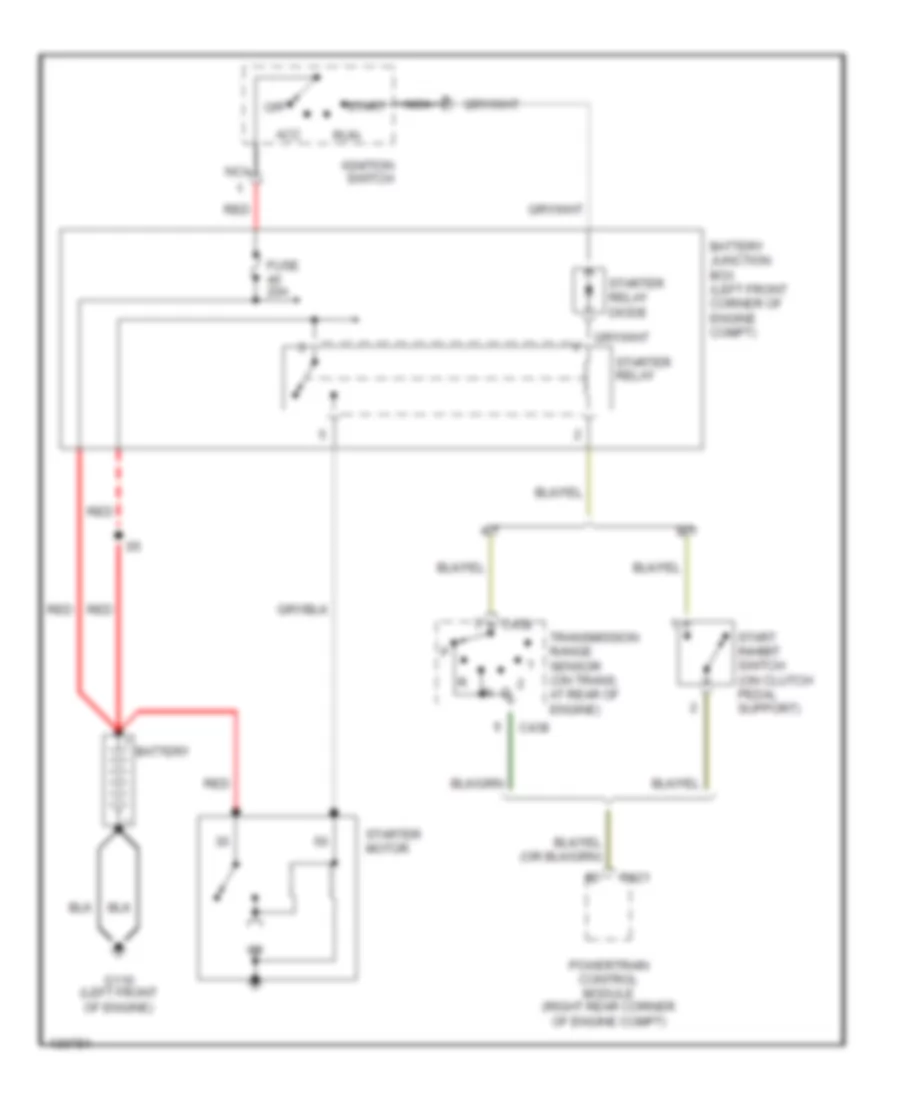
Starting Wiring Diagram for Mercury Cougar S 2001
List of elements for Starting Wiring Diagram for Mercury Cougar S 2001:
- A/t
- Acc
- Battery
- Battery junction box (left front corner of engine compt)
- C421
- C438
- Fuse 20a
- G110 (left front of engine)
- Ignition switch
- M/t
- Nca
- Off
- Powertrain control module (right rear corner of engine compt)
- Red
- Run
- Start
- Start inhibit switch (on clutch pedal support)
- Starter motor
- Starter relay
- Starter relay diode
- Transmission range sensor (on trans, at rear of engine)
SUPPLEMENTAL RESTRAINTS
Supplemental Restraint Wiring Diagram for Mercury Cougar S 2001
List of elements for Supplemental Restraint Wiring Diagram for Mercury Cougar S 2001:
- (behind left side dash panel) s359
- (bottom of right "a" pillar) g901
- (left front side of engine) g112
- 15-gg14
- 15-ja10
- 15s-ja11
- 15s-ja37
- 15s-ja38
- 15s-ja43
- 15s-ja8
- 8-ja37
- 8-ja38
- 8-ja7
- 9-ja37
- 9-ja38
- 91-ja10
- 91-ja10c
- 91s-ja11
- 91s-ja14
- 91s-ja37
- 91s-ja38
- 91s-ja43
- 91s-ja8
- Air bag
- Air bag diagnostic monitor (behind left side of dash, on steering column)
- Air bag sliding contact
- C362
- C364
- C808a
- C808b
- Central junction box (under left side of dash)
- Computer data lines system
- Driver air bag module
- Fuse 30 7.5a
- Fuse 38 10a
- Ground
- Ground switched
- Hot in run or start
- Ignition switched feed
- Instrument cluster
- Left side air bag module (on side of left front seat)
- Left side air bag sensor (under left front seat)
- Micro- processor
- Nca
- Passenger air bag module
- Power distribution system
- Right side air bag module (on side of right front seat)
- Right side air bag sensor (under right front seat)
- Sensor signal
- Sensor signal return
- Solid state
TRANSMISSION
2.5L
2.5L, A/T Wiring Diagram for Mercury Cougar S 2001
List of elements for 2.5L, A/T Wiring Diagram for Mercury Cougar S 2001:
- (behind left side of dash)
- (left front corner of engine compt) battery junction box
- (on cyl head) s425
- (on engine)
- (on engine) s407
- (on engine) s59
- (right rear corner of engine compt) powertrain control module (pcm)
- (right rear of engine compt)
- (right side of engine bulkhead)
- (right side of engine compt)
- 15-re8
- 15-re8a
- 15s-re13
- 15s-ta21
- 29-re8
- 3-2/ccs
- 4-re8
- 5-re8
- 7-re8
- 8-gb10
- 8-gg18
- 8-ra1
- 8-rj22
- 8-rj28
- 8-rj29
- 8-rj6
- 8-ta26
- 8-ta27
- 8-ta9
- 9-re8
- 9-re8a
- 9-rj22
- 9-rj29
- 91-re21
- 91-re8
- 91-re8a
- 91-re8b
- 91-re8c
- 91s-rd7
- 91s-ta17
- 91s-ta20
- 91s-ta23
- 91s-ta24
- 91s-ta25
- Anti-lock brakes system
- Anti-theft central locking module
- Battery junction box (left front corner of engine compt)
- Brake pedal position switch
- C362
- C369
- C808a
- Center of dash)
- Central junction box (under left side of dash)
- Cooling fan relays, a/c wot relay, evap purge & vent valves, pats transceiver module, heated o2 sensors
- Data link connector (under
- Dlc +
- Dlc -
- Dlc power
- Ect
- Electronic pressure control solenoid
- Engine controls system
- Engine coolant temperature sensor (upper right rear of engine)
- Eps
- Exterior lights system
- Fuse 15a
- Fuse 20a
- Fuse 3a
- Fuse 7.5a
- G1 (left front of engine)
- G22 (left front of engine compt)
- Gearshift lever unit (under center console)
- Ground
- Hot at all times
- Hot in run or start
- Ignition
- Ignition relay diode
- Ignition transformers
- Instrument cluster
- Kap
- Maf sig
- Mass air- flow sensor (on air cleaner housing assembly)
- Mil
- Mil ind
- Modulated lock-up solenoid
- Nca
- O/d off
- Pcm power relay
- Red
- Ref volt
- Return
- S130 (behind left side of dash)
- S147
- S250
- S281
- S282
- S363
- S366
- S367 (behind left side of dash)
- S48
- S53
- S54
- S62
- S66 (on trans)
- Shift sol 1
- Shift sol 2
- Shift solenoid 1
- Shift solenoid 2
- Shift solenoid 3
- Sig return
- Stop lamp
- Stoplamp switch (on bracket, above brake pedal)
- Tach
- Tachometer
- Tcc
- Tcs
- Throttle position sensor (on throttle body)
- Tps signal
- Tr sens
- Trans temp
- Transmission fluid temperature sensor
- Transmission harware unit
- Transmission range sensor (on transmission, rear of engine)
- Tss
- Turbine shaft speed sensor (on transmission)
- Vehicle speeed sensor (right side of transaxle)
- Vss
- Vss return
TRUNK, TAILGATE, FUEL DOOR
Trunk/Tailgate Release Wiring Diagram for Mercury Cougar S 2001
List of elements for Trunk/Tailgate Release Wiring Diagram for Mercury Cougar S 2001:
- (2000)
- (2001)
- (left rear of vehicle)
- (not used)
- Anti-theft/ central locking module (on center of right "a" pillar)
- C171
- C360
- C362
- C451a
- C451b
- C58
- C808a
- Central junction box (under left side of dash)
- Fuse 25 20a
- Fuse 30 7.5a
- G203 (right kick panel)
- G404
- G404 (left rear of vehicle)
- Hot at all times
- Hot in run or start
- Instrument cluster
- Interior lights system
- Liftgate/ decklid release switch (under left side of dash)
- Liftgate/ decklid switch (rear, center of vehicle)
- Nca
- S355
- Tailgate motor (center rear of luggage compt)
- To lever unit gearshift
- To instrument cluster
- To luggage compt lamp
- To tailgate ajar relay 1
WARNING SYSTEMS
Warning System Wiring Diagrams for Mercury Cougar S 2001
List of elements for Warning System Wiring Diagrams for Mercury Cougar S 2001:
- (not used)
- Acc
- Anti-theft system
- Battery
- Battery junction box (left front corner of engine compt)
- Belt minder module (behind left side of dash)
- C23
- C320
- C361
- C362
- C364
- C366
- C369
- C370
- C372
- C456
- C504a
- C504b
- C808b
- Central junction box (under left side of dash)
- Central timer module (ctm) (under left side of dash, on central junction box)
- Courtesy lamp relay
- Defogger system
- Defrost refrost
- Defrost sw
- Door locks system
- Doors sw
- Driver door sw
- Engine controls system
- Fuse 60a
- Fuse 7.5a
- G203 (right kick panel)
- G404 (left rear of vehicle)
- G405 (right rear of vehicle)
- Ground
- Ground swd
- Head
- Hot at all times
- Ignition
- Ignition sw
- Ignition switch
- Illum entry
- Instrument cluster
- Instrument cluster system
- Inter wiper sw
- Key illum sw
- Key in ign sw
- Key in ignition switch
- Left front door courtesy lamp switch
- Lock
- Main light switch
- Nca
- Off
- Park
- Park lamp sw
- Power (bat)
- Rear window defrost relay
- Red
- Remote entry in
- Right front door courtesy lamp switch
- Run
- S17
- S341
- S354
- S355
- S356
- S43
- Seat belt buckle switch (in driver's seat belt buckle)
- Seat belt ind
- Seat belt indicator
- Seat belt sw
- Sensor sig
- Start
- Washer sw
- Windshield wiper relay
- Wiper park
- Wiper/rate select
- Wiper/washer system
WIPER/WASHER
Wiper/Washer Wiring Diagram for Mercury Cougar S 2001
List of elements for Wiper/Washer Wiring Diagram for Mercury Cougar S 2001:
- (2000)
- (2001)
- C367
- C369
- C369 c369
- C372
- C372 c372
- Central junction box (under left side of dash)
- Central timer module (under left side of dash)
- Fast
- Front washer on
- Fuse 20 10a
- G106 (left front of engine compartment)
- G203 (right kick panel)
- Higher option
- Hot in run and start
- Int
- Lower option
- Nca
- Norm
- Off
- Park
- Rear washer on
- Rear window wiper motor (if equipped)
- Rear wiper on
- Run
- S358
- S423
- Sngl wipe
- Two-way washer pump motor (in fluid reservoir)
- Variable intermittent switch
- Windshield wiper motor
- Windshield wiper relay
- Wiper/ washer switch

 Čeština
 Dansk
Dansk Deutsch
 Ελληνικά
 English
 English
 Español
 Suomi
Suomi Français
 עברית
עברית Hrvatski
 Magyar
 Italiano
 日本語
日本語 한국어
한국어 Nederlands
 Polski
 Português
 Português
 Română
 Русский
 Slovenčina
 Slovenščina
 Svenska
 Türkçe
 中文 (中国)