AIR CONDITIONING
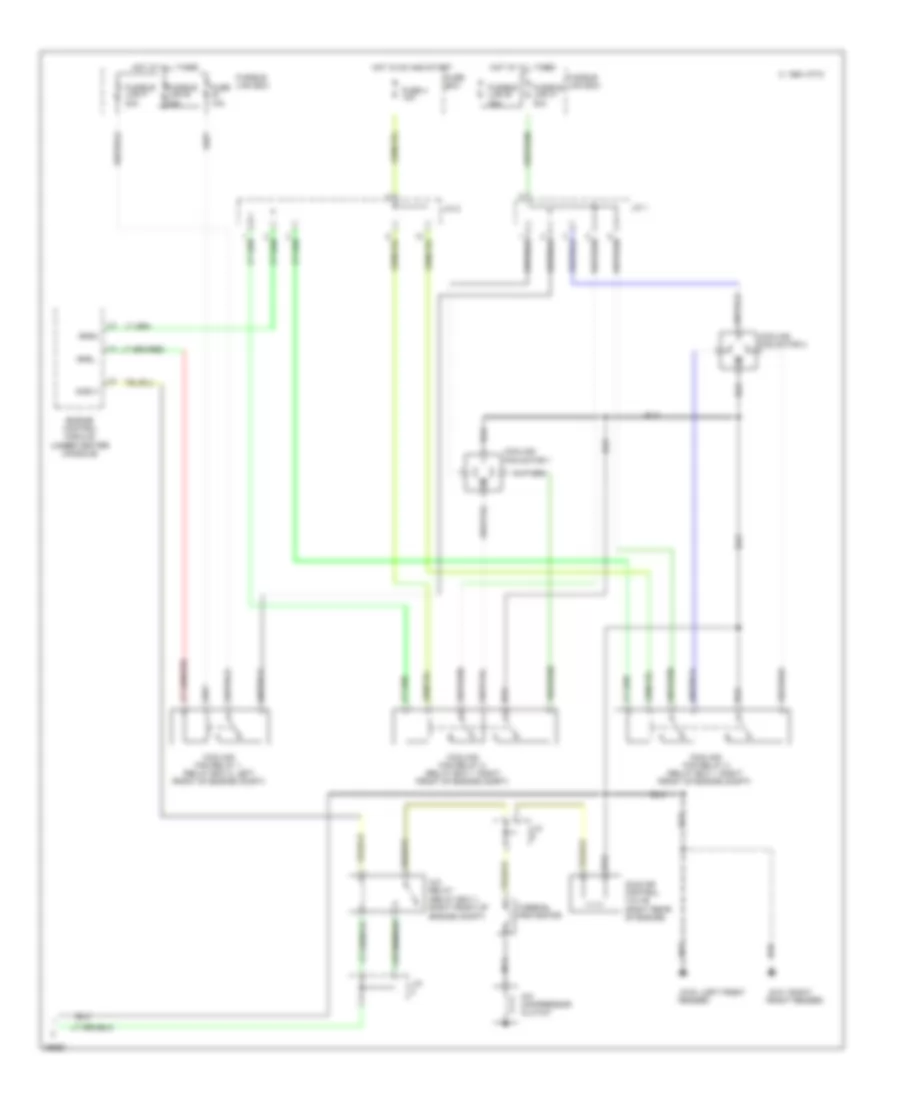
A/C Wiring Diagram, Auto A/C (1 of 2) for Nissan Altima GXE 1997
 https://portal-diagnostov.com/license.html
Automotive Electricians Portal FZCO
Automotive Electricians Portal FZCO
https://portal-diagnostov.com/license.html
https://portal-diagnostov.com/license.html
Automotive Electricians Portal FZCO
Automotive Electricians Portal FZCO
List of elements for A/C Wiring Diagram, Auto A/C (1 of 2) for Nissan Altima GXE 1997:
- (center g206
- (center of i/p)
- (left side
- (right de-
- (right rear of engine)
- (right side g203
- (right side of i/p)
- +5v
- 1994 vftc c
- A/mix actr
- A/mix pbr
- Air mix door motor
- Amb sen
- Ambient sensor (center front
- Auto amp
- B/l
- Bat
- Blower hi relay (right side of i/p)
- Blower motor
- Blwr rly
- Def
- Engine control module (below center console)
- F/d
- Fan control amp
- Fan f/b
- Fan gate
- Fascia)
- Foot
- Fresh vent door motor
- Froster grille)
- Fuse 10a
- Fuse 20a
- Fuse 26 10a
- Fuse block
- Fv actr
- Gnd
- Hot at all times
- Hot in on
- I/p)
- Ign
- Ill
- In vehicle sensor
- Incar sens
- Intake 20% fre/fre
- Intake actr
- Intake door motor
- Intake fre/rec
- Intake rec 20% fre
- Interior lights system
- Kick panel)
- Mode actr
- Mode def b/l foot
- Mode door motor (center of i/p)
- Mode f/d def
- Mode foot f/d vent
- Mood vent
- Of i/p)
- Or start
- Pnk
- Position switch
- Psdw
- Red
- Sens gnd
- Sun sensor
- Sunload sensor
- Thermal transmitter
- Thermo amp
- Thermo amp
- Thermo control amp
- Triple pressure switch (left front of engine compt)
- Vent
- W/t sens
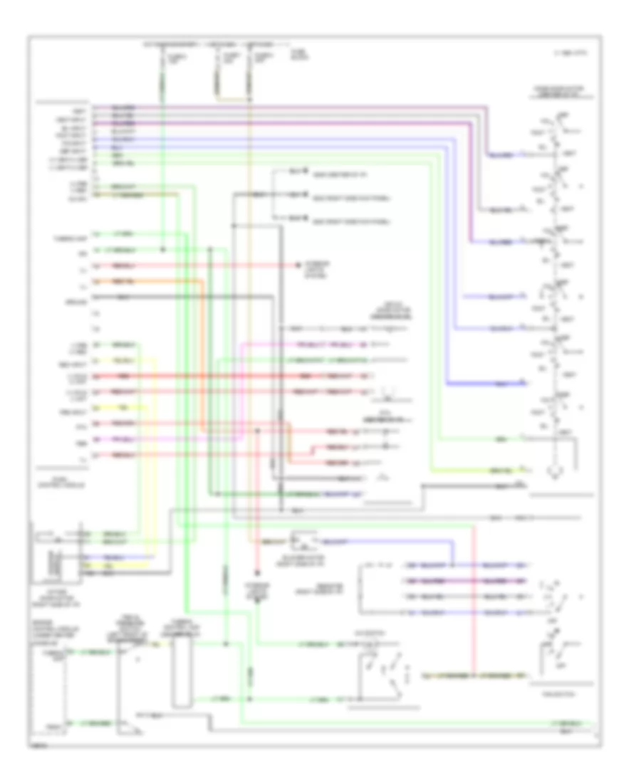
A/C Wiring Diagram, Auto A/C (2 of 2) for Nissan Altima GXE 1997
List of elements for A/C Wiring Diagram, Auto A/C (2 of 2) for Nissan Altima GXE 1997:
- (left front g100
- (right g101
- 1994 vftc c
- A/c compressor clutch
- A/c relay (relay box 1, right front of engine compt)
- Acrly
- Cooling fan motor 1
- Cooling fan motor 2
- Cooling fan relay 1 (relay box 2, left front of engine compt)
- Cooling fan relay 2 (relay box 1, right front of engine compt)
- Cooling fan relay 3 (relay box 1, right front of engine compt)
- Engine control module (under center console)
- Fender)
- Front fender)
- Fuse 10a
- Fuse 4 10a
- Fuse box
- Fusible link f 30a
- Fusible link h 30a
- Fusible link box
- Fusible link e 75a
- Hot at all times
- Hot in on and start
- Idle air control valve (right rear of engine)
- J/c
- J/c 1
- J/c 2
- Nca
- Rfrh
- Rfrl
- Thermal protector
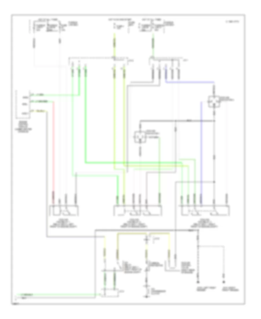
A/C Wiring Diagram, Manual A/C (1 of 2) for Nissan Altima GXE 1997
List of elements for A/C Wiring Diagram, Manual A/C (1 of 2) for Nissan Altima GXE 1997:
- (+) cold (-) hot
- (+) fre (-) rec
- (+) vent/(-) def
- (-) cold (+) hot
- (-) fre (+) rec
- (-) vent/(+) def
- (center of i/p)
- (center of i/p) g206
- (right side kick panel) g203
- (right side of i/p)
- 1994 vftc c
- A/c sw
- A/c switch
- Air mix door motor
- B/l
- B/l input
- Blower motor
- Console)
- Def
- Def input
- Engine control module (under center
- F/d
- F/d input
- Fan switch
- Foot
- Foot input
- Fre input
- Fuse 6 10a
- Fuse 7 20a
- Fuse 8 20a
- Fuse block
- Ground
- Hot in on
- Hot in on or start
- Ign
- Ill
- Intake door motor
- Interior lights system
- Mode door motor (center of i/p)
- Off
- Pbr
- Psdw
- Ptc
- Push control module
- Rec input
- Red
- Resistor
- Switch position
- Thermo amp
- Thermo control amp
- Triple pressure switch (left front of engine compt)
- Vent
- Vent input
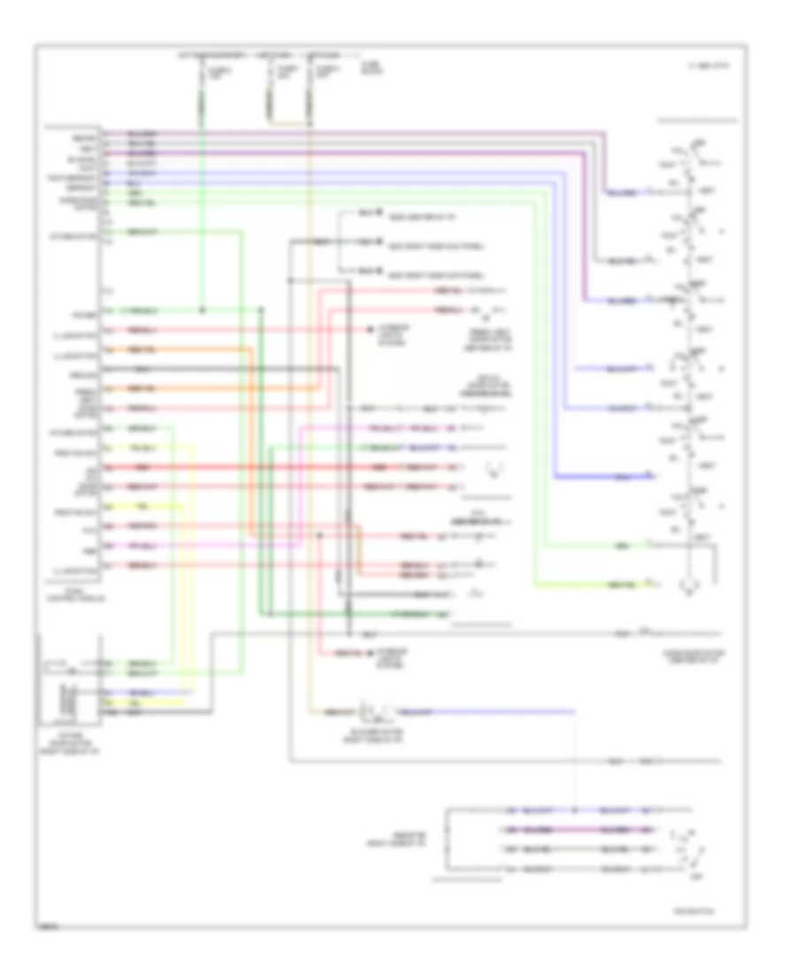
A/C Wiring Diagram, Manual A/C (2 of 2) for Nissan Altima GXE 1997
List of elements for A/C Wiring Diagram, Manual A/C (2 of 2) for Nissan Altima GXE 1997:
- (left front g100
- (right g101
- 1994 vftc c
- A/c compressor clutch
- A/c relay (relay box 1, right front of engine compt)
- Acrly
- Cooling fan motor 1
- Cooling fan motor 2
- Cooling fan relay 1 (relay box 2, left front of engine compt)
- Cooling fan relay 2 (relay box 1, right front of engine compt)
- Cooling fan relay 3 (relay box 1, right front of engine compt)
- Engine control module (under center console)
- Fender)
- Front fender)
- Fuse 10a
- Fuse 4 10a
- Fuse box
- Fusible link f 30a
- Fusible link h 30a
- Fusible link box
- Fusible link e 75a
- Hot at all times
- Hot in on and start
- Idle air control valve (right rear of engine)
- J/c 1
- J/c 2
- J/c 6
- Nca
- Rfrh
- Rfrl
- Thermal protector
Heater Wiring Diagram for Nissan Altima GXE 1997
List of elements for Heater Wiring Diagram for Nissan Altima GXE 1997:
- (center of i/p)
- (center of i/p) g206
- (right side kick panel) g203
- (right side of i/p)
- 1994 vftc c
- Air mix
- Air mix door motor
- B/l
- Bi-level
- Blower motor
- Def
- Defrost
- Door motor
- F/d
- Fan switch
- Foot
- Foot/defrost
- Fresh vent
- Fresh vent door motor
- Fuse 6 10a
- Fuse 7 20a
- Fuse 8 20a
- Fuse block
- Ground
- Hot in on
- Hot in on or start
- Illumination
- Intake door motor
- Intake motor
- Interior lights system
- Mode door motor
- Mode door motor (center of i/p)
- Off
- Pbr
- Position sw
- Power
- Ptc
- Push control module
- Recirc
- Red
- Resistor
- Switch position
- Vent
ANTI-LOCK BRAKES
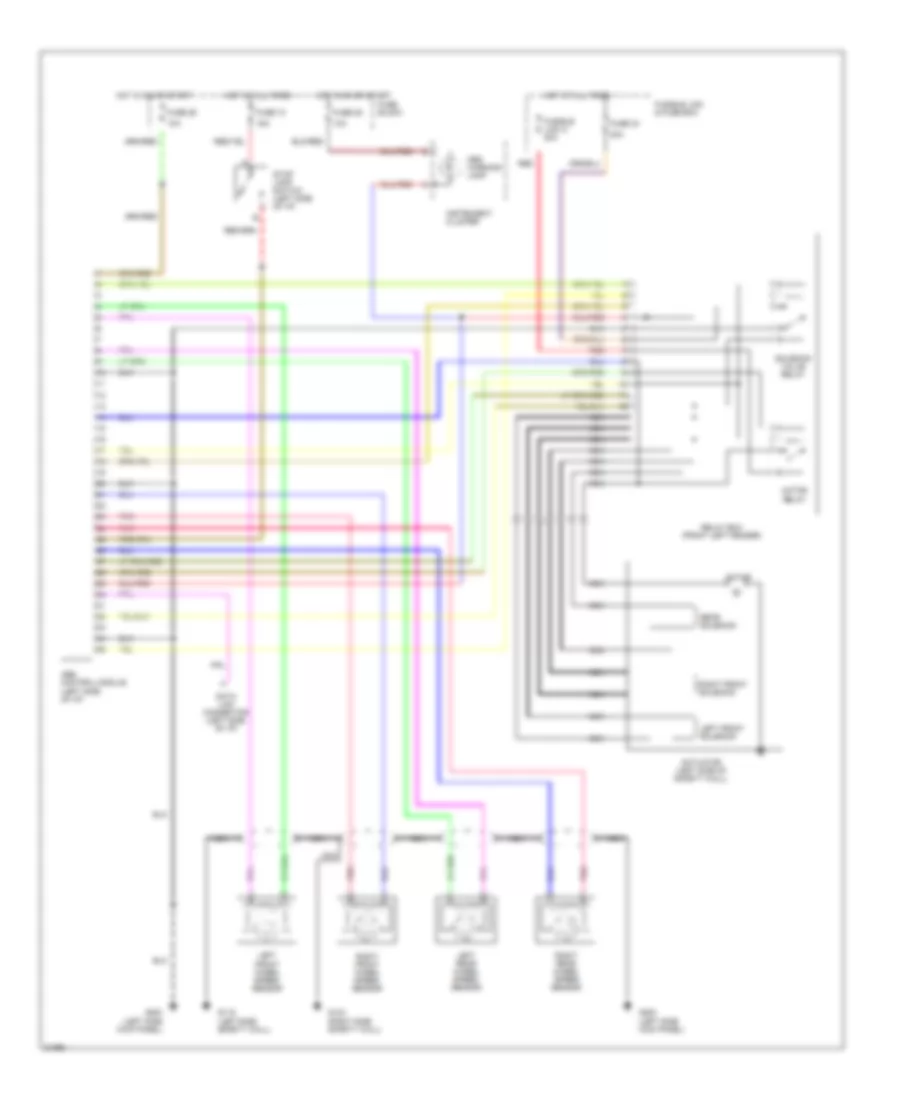
Anti-lock Brake Wiring Diagrams for Nissan Altima GXE 1997
List of elements for Anti-lock Brake Wiring Diagrams for Nissan Altima GXE 1997:
- 10a
- 15a
- 20a
- Abs control module (left side of i/p)
- Abs warning lamp
- Actuator (left side of safety wall)
- Data link connector (left side of i/p)
- Fuse 18
- Fuse 25
- Fuse 26
- Fuse 34
- Fuse block
- Fusible link & fuse box
- Fusible link a 20a
- G116 (left side safety wall)
- G123 (right side safety wall)
- G200 (left side kick panel)
- Hot at all times
- Hot in on or start
- Instrument cluster
- Left front solenoid
- Left front wheel speed sensor
- Left rear wheel speed sensor
- Motor
- Motor relay
- Nca
- Pnk
- Rear solenoid
- Red
- Relay box (front left fender)
- Right front solenoid
- Right front wheel speed sensor
- Right rear wheel speed sensor
- Solenoid valve relay
- Stop lamp switch (left side of i/p)
ANTI-THEFT
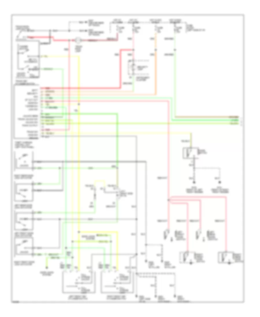
Anti-theft Wiring Diagram (1 of 2) for Nissan Altima GXE 1997
List of elements for Anti-theft Wiring Diagram (1 of 2) for Nissan Altima GXE 1997:
- (center rear
- Acc
- Batt
- Closed
- Door locks system
- Door sw
- Full stroke
- Full stroke lock
- Full stroke unlock
- Fuse 10a
- Fuse block (left side of i/p)
- G100 (front of left front fender)
- G101 (front of right front fender)
- G202 (left side of i/p)
- G203 (right kick panel)
- G305 (right "b" pillar)
- G308 (left "b" pillar)
- G407
- Ground
- Hood
- Hood sw
- Hot at all times
- Hot in acc or run
- Hot in run or start
- Instrument cluster
- J/c-7 (right side of i/p)
- Key cyl withdrawn
- Left front door lock actuator
- Left front door switch
- Left front key cylinder switch
- Left rear door lock actuator
- Left rear door switch
- Lock
- Lock sw
- Mid stroke
- Of trunk)
- Open
- Panic output
- Red
- Right front door lock actuator
- Right front door switch
- Right front key cylinder switch
- Right rear door lock actuator
- Right rear door switch
- Security
- Security lamp
- St cut out
- Switch
- Tamper sw
- Tamper switch
- Theft warning control unit (left kick panel)
- Trunk key cylinder switch
- Trunk room lamp
- Trunk room lamp switch
- Trunk sw
- Trunk unlock sw
- Unlock
- Unlock sens
- Unlock sw
- Unlock switch
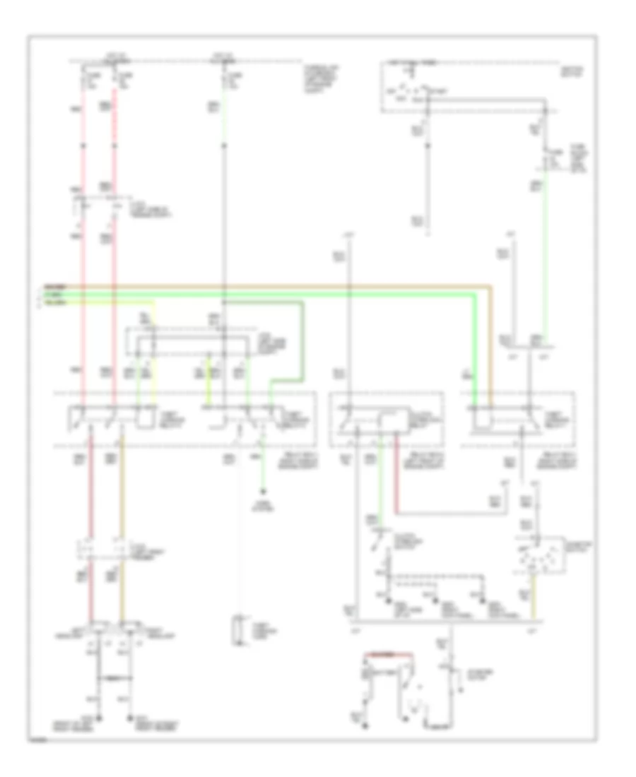
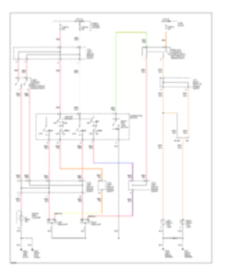
Anti-theft Wiring Diagram (2 of 2) for Nissan Altima GXE 1997
List of elements for Anti-theft Wiring Diagram (2 of 2) for Nissan Altima GXE 1997:
- A/t
- Acc
- B nca
- Battery
- Clutch interlock relay
- Clutch interlock switch
- Compt)
- Fuse 10a
- Fuse 15a
- Fuse block (left
- Fusible link & fuse box (left front of engine
- G100 (front of left front fender)
- G101 (front of right front fender)
- G202 (left side of i/p)
- G203 (right kick panel)
- Headlamp
- Horn
- Horn system
- Hot at all times
- Ignition switch
- Inhibitor switch
- J/c-3 (left side of engine compt)
- J/c-5 (left front fender)
- J/c-6 (left side of engine compt)
- Left
- M/t
- Nca
- Off
- Red
- Relay box-1 (right side of engine compt)
- Relay box-2 (left front of engine compt)
- Right headlamp
- Run
- Side of i/p)
- Start
- Starter motor
- Theft
- Theft warning relay-1
- Theft warning relay-2
- Theft warning relay-3
- Warning
BODY COMPUTER
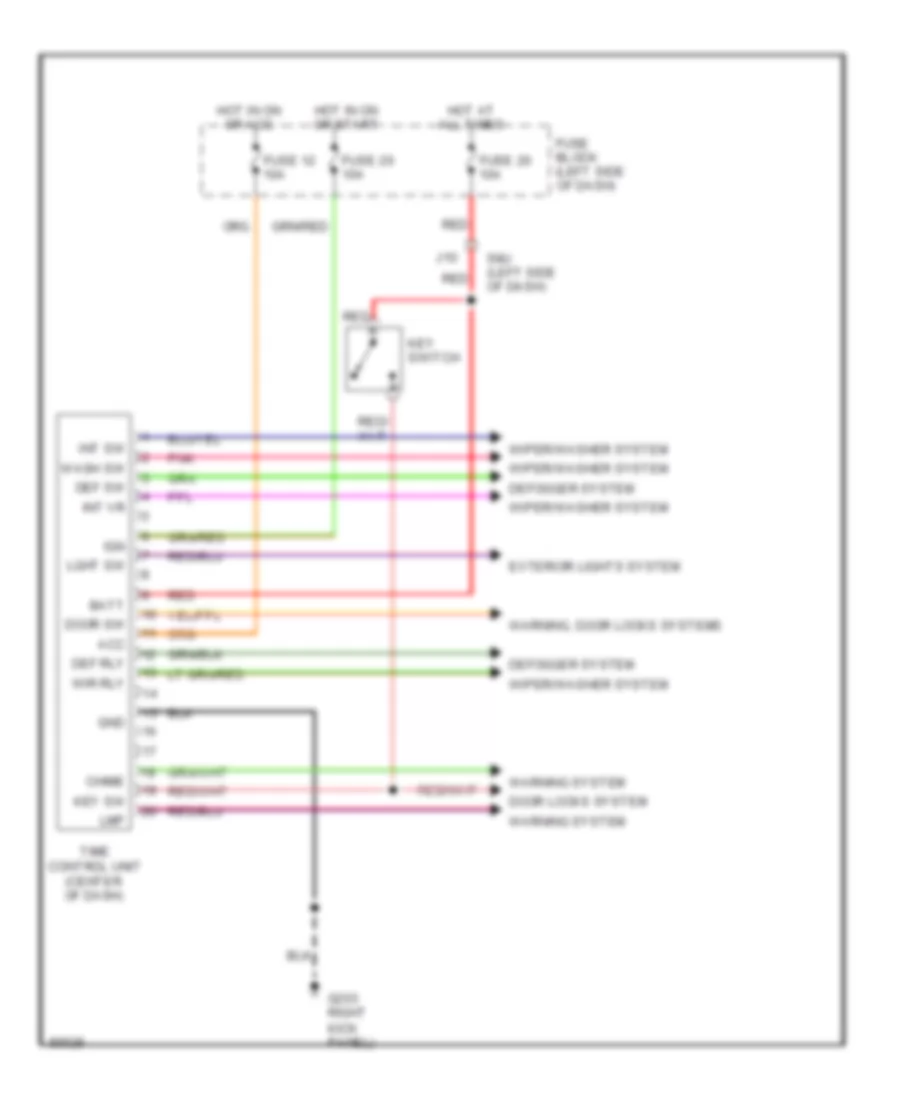
Time Control Unit Wiring Diagram for Nissan Altima GXE 1997
List of elements for Time Control Unit Wiring Diagram for Nissan Altima GXE 1997:
- Acc
- Batt
- Chime
- Def rly
- Def sw
- Defogger system
- Door locks system
- Door sw
- Exterior lights system
- Fuse 12 10a
- Fuse 20 10a
- Fuse 26 10a
- Fuse block (left side of dash)
- G203 right
- Gnd
- Hot at all times
- Hot in on or acc
- Hot in on or start
- Ign
- Int sw
- Int vr
- J10
- Key sw
- Key switch
- Kick panel)
- Lght sw
- Lmp
- Pnk
- Red
- Smj (left side of dash)
- Time control unit (center of dash)
- Warning system
- Warning, door locks systems
- Wash sw
- Wiper/washer system
- Wir rly
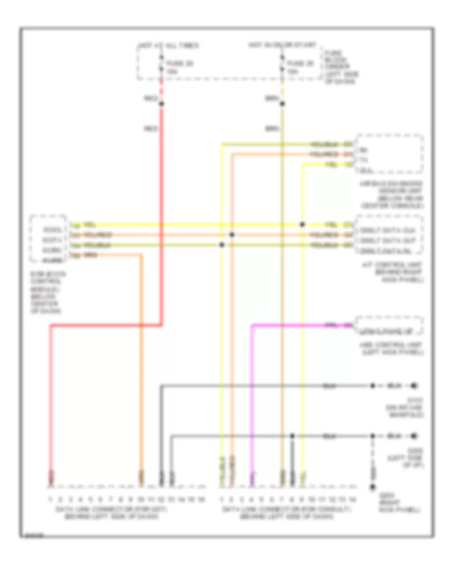
COMPUTER DATA LINES
Computer Data Lines for Nissan Altima GXE 1997
List of elements for Computer Data Lines for Nissan Altima GXE 1997:
- A/t control unit (behind right kick panel)
- Abs control unit (left kick panel)
- Air bag diagnosis sensor unit (below rear center console)
- Clx
- Cnslt data clk
- Cnslt data in
- Cnslt data out
- Data link connector (for consult) (behind left side of dash)
- Data link connector (for gst) (behind left side of dash)
- Ecm (eccs control module) (below center of dash)
- Fuse 20 10a
- Fuse 25 10a
- Fuse block (under left side of dash)
- G131 (on intake manifold)
- G202 (left side of i/p)
- G203 (right kick panel)
- Hot at all times
- Hot in on or start
- Kline
- L/diag wake up
- Red
- Scicl
- Scirx
- Scitx
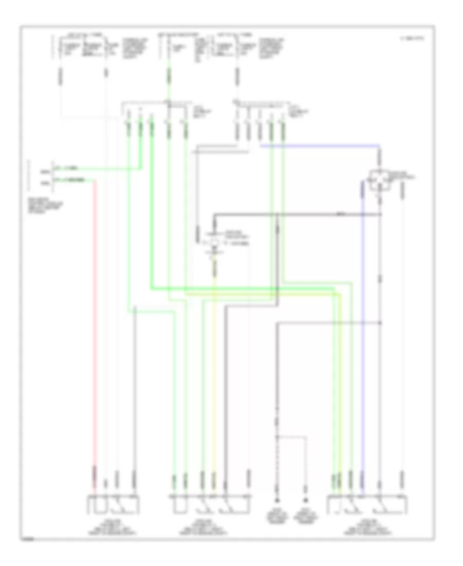
COOLING FAN
Cooling Fan Wiring Diagram for Nissan Altima GXE 1997
List of elements for Cooling Fan Wiring Diagram for Nissan Altima GXE 1997:
- 1994 vftc c
- Cooling fan motor 1
- Cooling fan motor 2
- Cooling fan relay 1 (relay box 2, left front of engine compt)
- Cooling fan relay 2 (relay box 1, right front of engine compt)
- Cooling fan relay 3 (relay box 1, right front of engine compt)
- Ecm (eccs control module) (below center of dash)
- Fuse 10a
- Fuse block (left side of i/p)
- Fuse 4 10a
- Fusible link f 30a
- Fusible link h 30a
- Fusible link & fuse box (left front of engine compt)
- Fusible link e 75a
- G100 (front of left front fender)
- G101 (front of right front fender)
- Hot at all times
- Hot in on and start
- J/c 1 (in relay box 1)
- J/c 2 (in relay box 1)
- Rfrh
- Rfrl
CRUISE CONTROL
Cruise Control Wiring Diagram, A/T for Nissan Altima GXE 1997
List of elements for Cruise Control Wiring Diagram, A/T for Nissan Altima GXE 1997:
- A/t control unit (right kick panel)
- Act. cntrl
- Actuator control
- Air valve solenoid
- Ascd actuator (left side of safety wall)
- Ascd cancel switch (top of brake
- Ascd control unit (left side of dash)
- Ascd hold relay (relay box 2, left front fender)
- Ascd steering switch
- Ascd sw.
- Ascd switch
- Cancel
- Crs. cancl
- Cruise ind.
- Cruise signal
- Fuse & fusible link box (left front fender)
- Fuse 18 15a
- Fuse 25 10a
- Fuse 26 10a
- Fuse 35 10a
- Fuse block
- G100 (front of left front fender)
- G100 (left front fender)
- G206 (right kick panel)
- Ground
- Horn relay (relay box 1, right front fender)
- Horns system (horn)
- Hot at all times
- Hot in on or start
- Inhibitor relay (relay box 2, left front fender)
- Inhibitor switch (left side of transmission)
- Instrument cluster
- Interior lights system
- J/c 5 (left front fender)
- Nca
- Od cut
- Od cut signal
- Off
- Pedal support)
- Pnk
- Red
- Release valve solenoid
- Resume/ accelerate
- Set/coast
- Speed
- Speed- ometer
- Spiral cable
- St lmp sw.
- Steering switch
- Stop lamp switch (top of brake pedal support)
- Vacuum motor
- Vehicle speed sensor (top of trans.)
Cruise Control Wiring Diagram, M/T for Nissan Altima GXE 1997
List of elements for Cruise Control Wiring Diagram, M/T for Nissan Altima GXE 1997:
- Act. cntrl
- Actuator control
- Air valve solenoid
- Ascd actuator (left side of safety wall)
- Ascd cancel switch (top of brake
- Ascd clutch switch (top of clutch pedal support)
- Ascd control unit (left side of dash)
- Ascd hold relay (relay box 2, (left front fender)
- Ascd steering switch
- Ascd sw.
- Ascd switch
- Cancel
- Crs. cancl
- Cruise ind.
- Fuse & fusible link box (left front fender)
- Fuse 18 15a
- Fuse 26 10a
- Fuse 35 10a
- Fuse block
- G100 (left front fender)
- G202 (left side of dash)
- Ground
- Horn relay (relay box 1, right front fender)
- Horns system (horn)
- Hot at all times
- Hot in on or start
- Instrument cluster
- Interior lights system
- J/c 5 (left front fender
- Nca
- Od cut
- Off
- Pedal support)
- Pnk
- Red
- Release valve solenoid
- Resume/ accelerate
- Set/coast
- Speed
- Speed- ometer
- Spiral cable
- St lmp sw.
- Steering switch
- Stop lamp switch (top of brake pedal support)
- Vacuum motor
- Vehicle speed sensor (top of trans.)
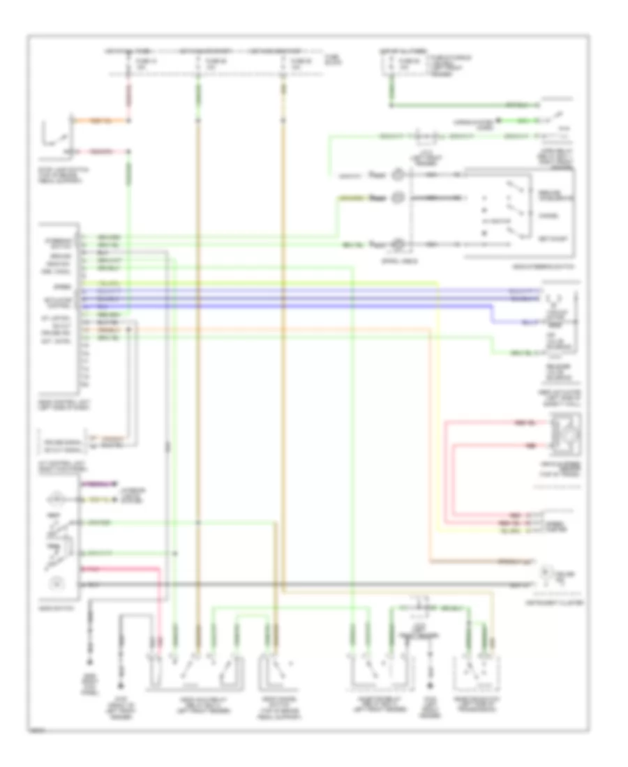
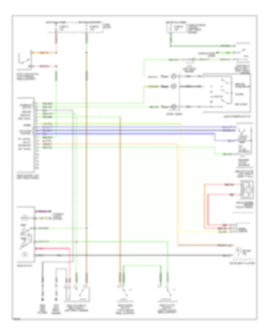
DEFOGGERS
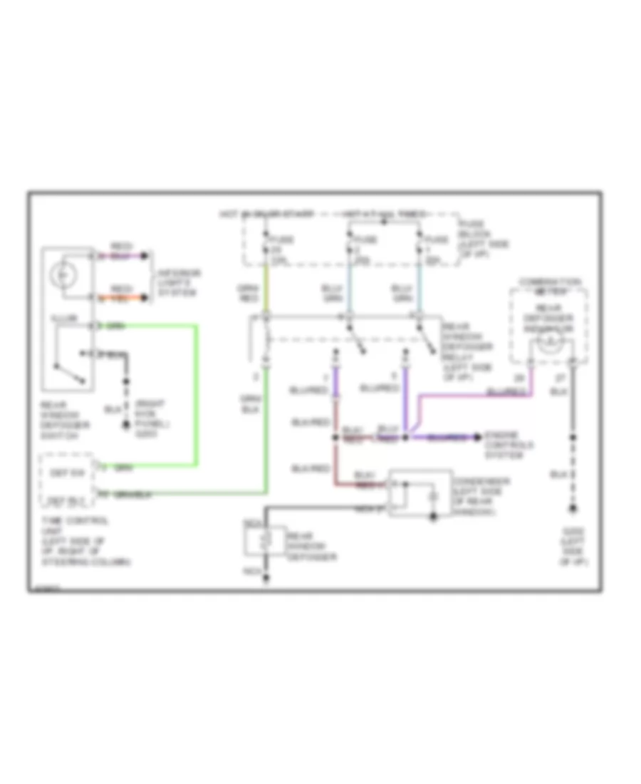
Defogger Wiring Diagram for Nissan Altima GXE 1997
List of elements for Defogger Wiring Diagram for Nissan Altima GXE 1997:
- (right kick panel) g203
- Combination meter
- Condenser (left side of rear window)
- Def rly
- Def sw
- Engine controls system
- Fuse 10a
- Fuse 20a
- Fuse block (left side of i/p)
- G202 (left side of i/p)
- Hot at all times
- Hot in on or start
- Illum
- Interior lights system
- Nca
- Rear defogger indicator
- Rear window defogger
- Rear window defogger relay (left side of i/p)
- Rear window defogger switch
- Time control unit (left side of i/p, right of steering column)
ENGINE PERFORMANCE
2.4L
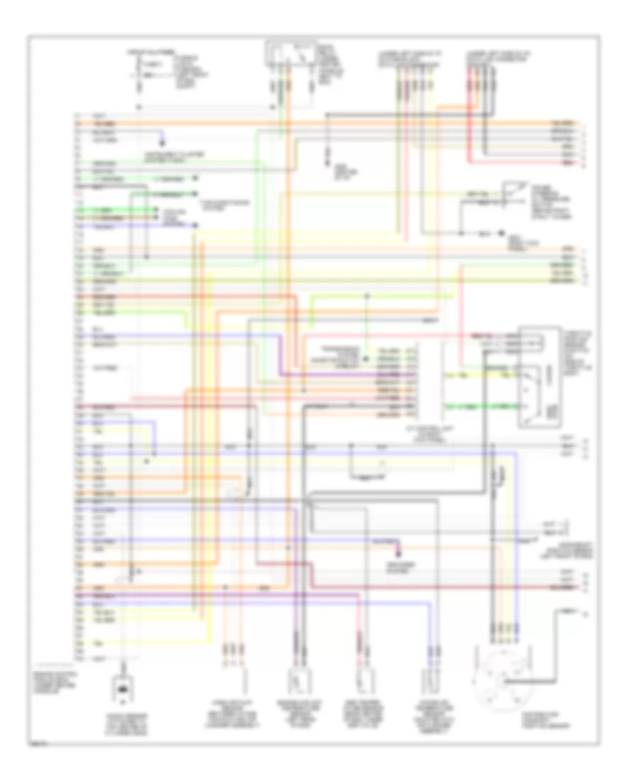
2.4L, Engine Performance Wiring Diagrams (1 of 2) for Nissan Altima GXE 1997
List of elements for 2.4L, Engine Performance Wiring Diagrams (1 of 2) for Nissan Altima GXE 1997:
- (under left side of i/p) data link connector (for gst)
- (under left side of i/p, on fuse block) data link connector
- 25a
- A/t control unit (in right kick panel)
- A/t only
- Air conditioning system
- Closed
- Cooling fans system
- Crankshaft position sensor (left front of eng)
- Defogger system
- Distributor/ camshaft position sensor
- Eccs relay (under center console, next to ecm)
- Egr temper- ature sensor (rear center of eng, under egr valve)
- Engine control module (ecm) (under center console)
- Engine coolant temperature sensor (left rear of eng)
- Fuse c
- Fusible link & fuse box (left front of eng compt)
- G203 (right kick panel)
- G206 (center of i/p)
- Hot at all times
- Instrument cluster system (tach)
- Intake air temperature sensor (mounted into air cleaner assembly)
- Knock sensor (attached to top center of cylinder head)
- Mass air flow sensor (between intake manifold and air cleaner assembly)
- Nca
- Power steering oil pressure switch (behind right strut tower)
- Red
- Throttle position sensor & switch (on side of throttle body)
- Transmission system (inhibitor switch & relay)
- Wide open
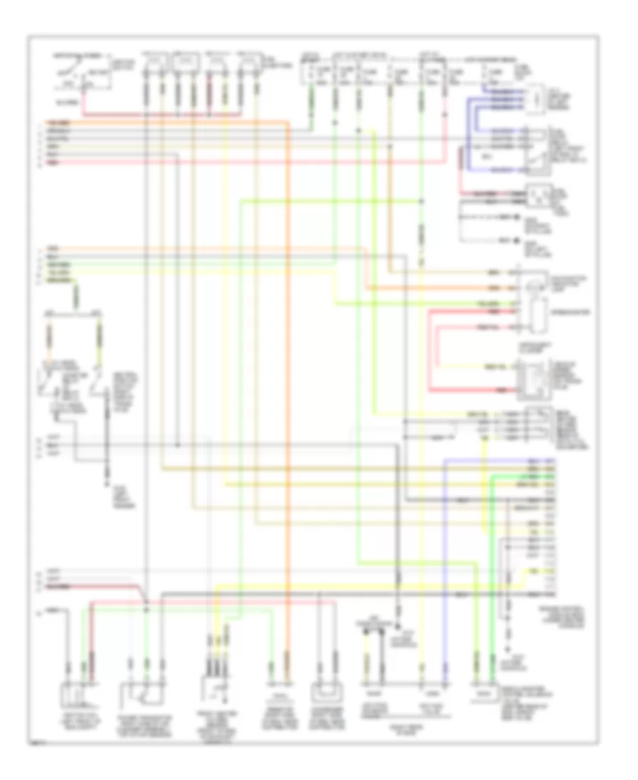
2.4L, Engine Performance Wiring Diagrams (2 of 2) for Nissan Altima GXE 1997
List of elements for 2.4L, Engine Performance Wiring Diagrams (2 of 2) for Nissan Altima GXE 1997:
- (intake manifold)
- (right rear of eng)
- (w/ ascd) (w/o ascd)
- 10a
- 1o1
- A/t
- Acc
- Air conditioning system
- Condenser (right side of eng, near distributor)
- Egr & canister control solenoid valve (center rear of eng, side of egr valve)
- Engine control module (ecm) (under center console)
- Front heated oxygen sensor (front of eng, on exhaust) manifold)
- Fuel injectors
- Fuel pump (in fuel tank)
- Fuel pump relay (left front of eng, in relay box 2)
- Fuse
- Fuse 10a
- Fuse 15a
- Fuse block (i/p)
- G100 (left front fender)
- G131
- G305 (on right "b" pillar)
- G308 (on left "b" pillar)
- Hot at all times
- Hot in start
- Hot in start or on
- Iacv-aac valve
- Iacv-ficd solenoid valve
- Ignition coil (left front of eng compt)
- Ignition switch
- Inhibitor relay (in relay box 2)
- Instrument cluster
- J/c 4 (center of left fender)
- M/t
- Malfunction indicator lamp
- Nca
- Neutral position switch (right side of trans- axle)
- Off
- Power transistor (right side of air cleaner assembly, top of maf sensor)
- Rear heated oxygen sensor (rear of catalytic converter)
- Red
- Resistor (right side of eng, near distributor)
- Smj
- Speedometer
- Start
- Vehicle speed sensor (on trans- axle)
EXTERIOR LIGHTS
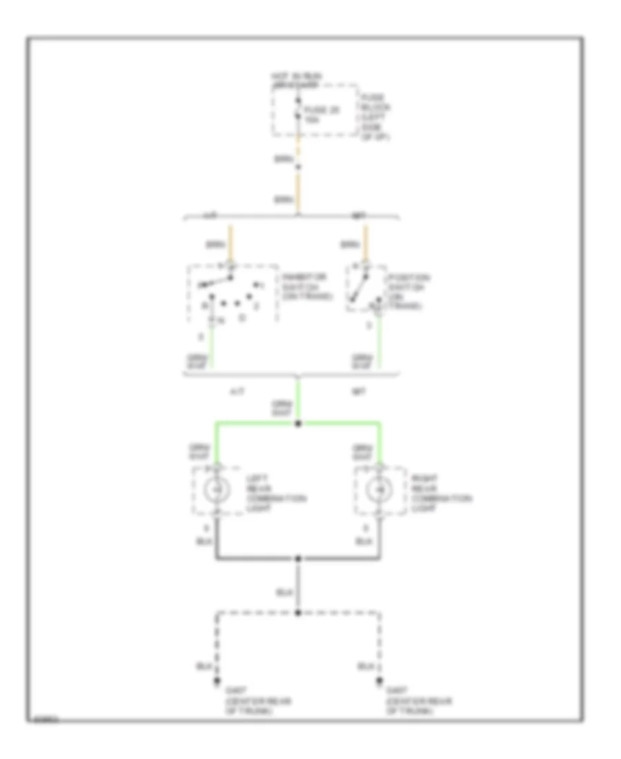
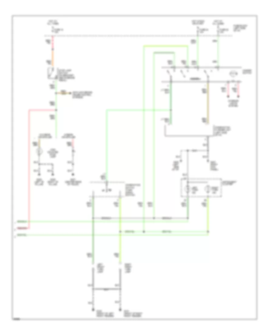
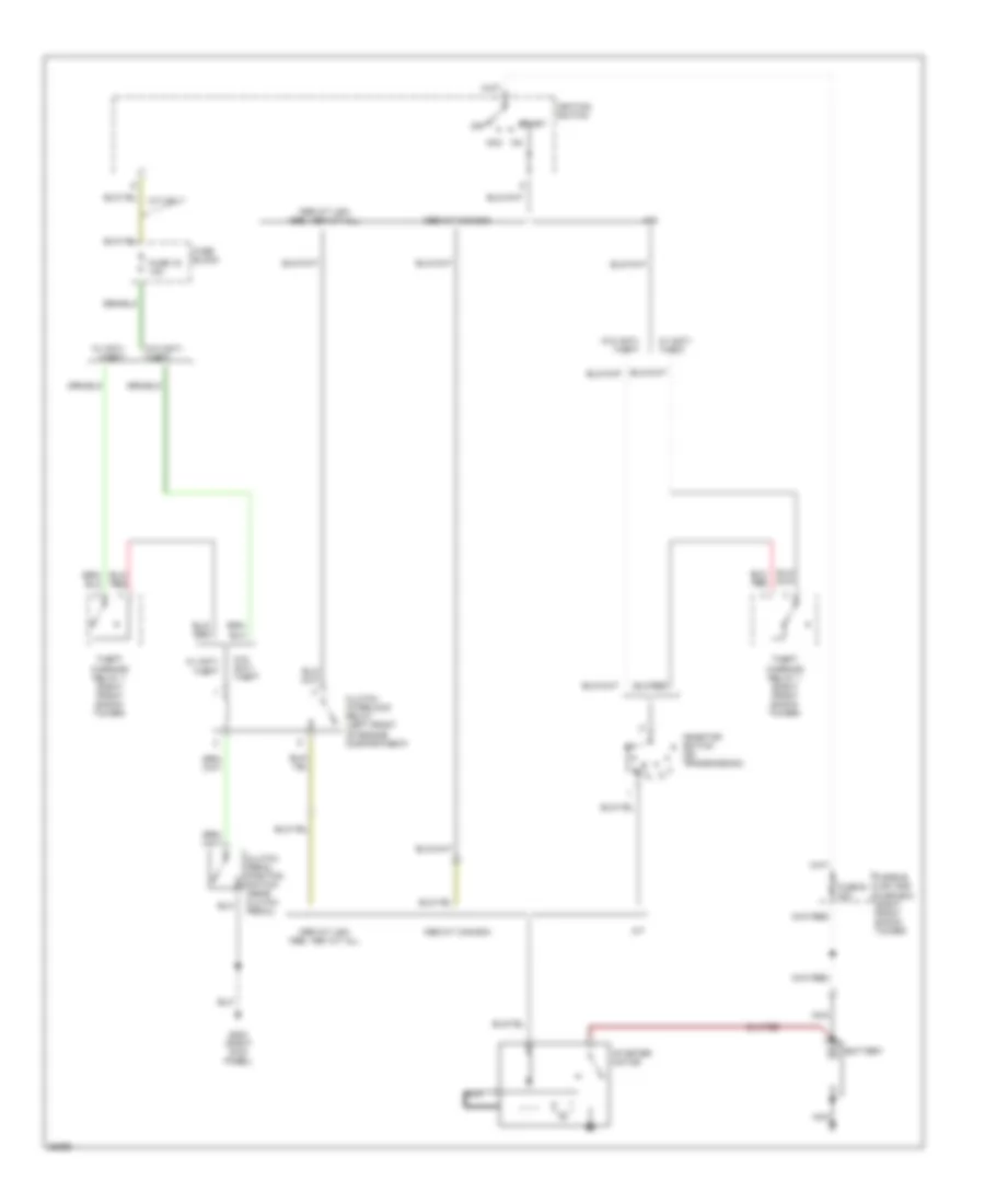
Back-up Lamps Wiring Diagram for Nissan Altima GXE 1997
List of elements for Back-up Lamps Wiring Diagram for Nissan Altima GXE 1997:
- (center rear of trunk)
- A/t
- Fuse 25 10a
- Fuse block (left side of i/p)
- G407
- Hot in run or start
- Inhibitor switch (on trans)
- Left rear combination light
- M/t
- Position switch (on trans)
- Right rear combination light
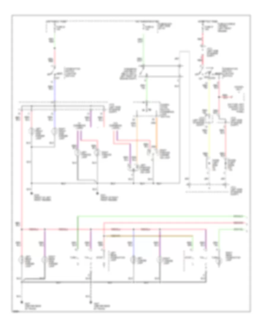
Exterior Lamps Wiring Diagram (1 of 2) for Nissan Altima GXE 1997
List of elements for Exterior Lamps Wiring Diagram (1 of 2) for Nissan Altima GXE 1997:
- 1st
- 2nd
- Canada only
- Combin- ation switch (cornering lamp switch)
- Combination switch (lighting switch)
- Cornering lamp relay (relay box 2, left front of engine compt)
- Daytime light control unit (right kick panel)
- Diode (left side of i/p)
- Fuse & fusible link box (left front fender)
- Fuse 23 15a
- Fuse 24 10a
- Fuse 37 15a
- Fuse block (left side of i/p)
- G100 (front of left front fender)
- G101 (front of right front fender)
- G407 (center rear of trunk)
- High
- Hot at all times
- Hot in run or start
- J/c 3 (left side of engine compt)
- J/c 4 (left side of engine compt)
- J/c 5 (left side of engine compt)
- J/c 6 (left side of engine compt)
- Left front side marker lamp
- Left license lamp
- Left parking lamp
- Left parking/ corner- ing lamp
- Left rear combination lamp
- Left rear side marker lamp
- Low
- Off
- Pass
- Red
- Right front side marker lamp
- Right license lamp
- Right parking lamp
- Right parking/ corner- ing lamp
- Right rear combination lamp
- Right rear side marker lamp
- Stop
- Tail
- Turn
- W/ cornering lamps
- W/o cornering lamps
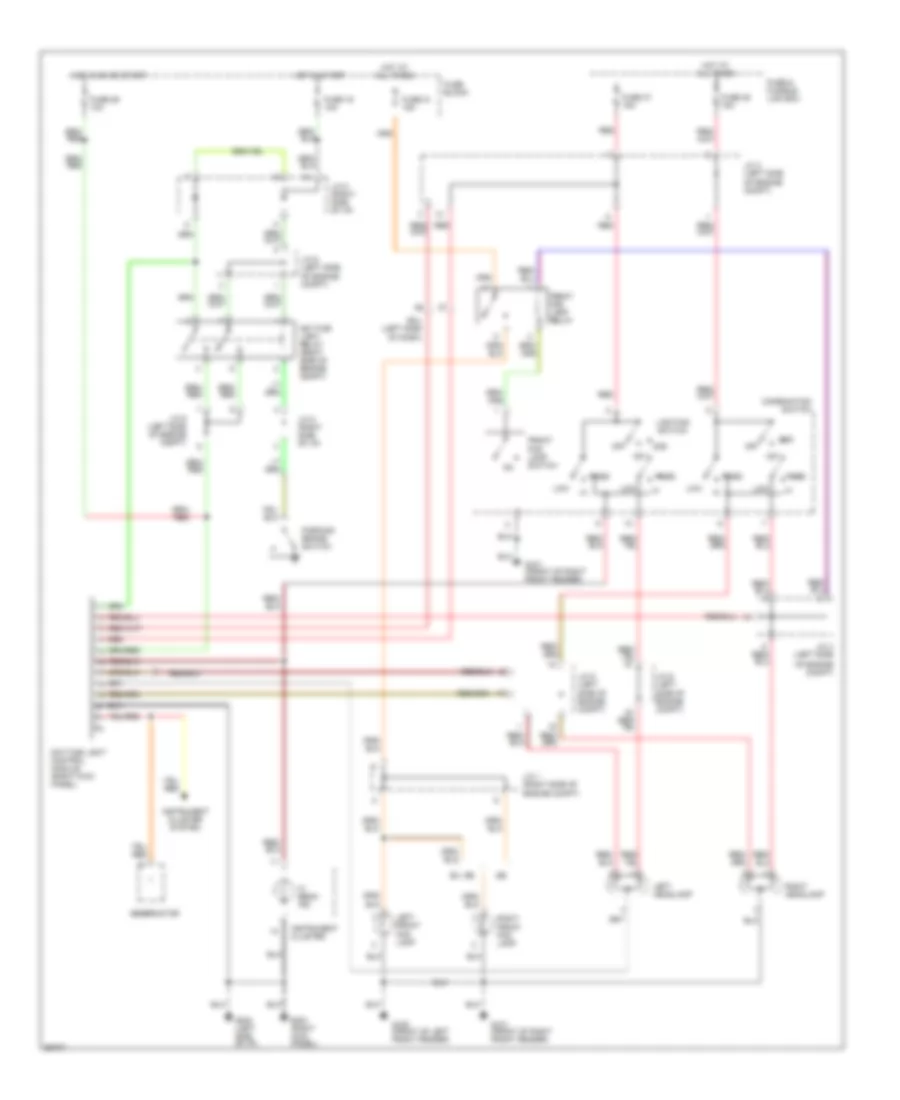
Exterior Lamps Wiring Diagram (2 of 2) for Nissan Altima GXE 1997
List of elements for Exterior Lamps Wiring Diagram (2 of 2) for Nissan Altima GXE 1997:
- Anti-lock brake, cruise control systems
- Combination flasher unit (left side of i/p)
- Combination switch (turn signal switch)
- Fuse 18 15a
- Fuse 22 10a
- Fuse 24 10a
- Fuse block (left side of i/p)
- G100 (front of left front fender)
- G101 (front of right front fender)
- G202 (left side of i/p)
- G203 (right kick panel)
- G305 (right "b" pillar)
- G308 (left "b" pillar)
- G407 (center rear of trunk)
- Hazard
- Hazard switch
- High mounted stop lamp
- Hot at all times
- Hot in run or start
- Ill
- Instrument cluster
- Interior lights system
- Left front turn lamp
- Left turn ind
- Right front turn lamp
- Right turn ind
- Stop lamp switch (on bracket, above brake pedal)
- W/o rear air spoiler
- W/rear air spoiler
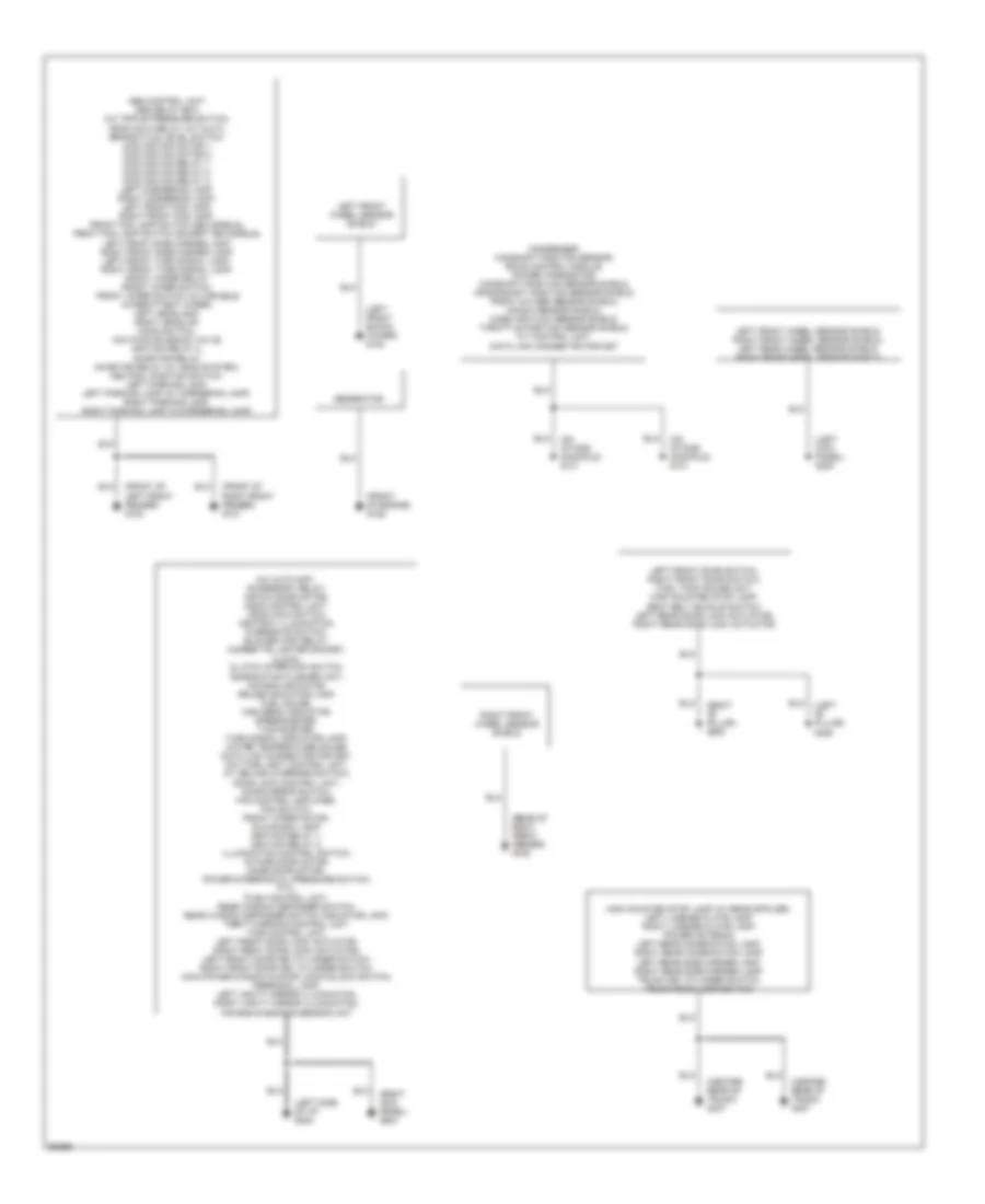
GROUND DISTRIBUTION
Ground Distribution Wiring Diagram for Nissan Altima GXE 1997
List of elements for Ground Distribution Wiring Diagram for Nissan Altima GXE 1997:
- (center rear of trunk) g407
- (front of engine) g125
- (front of left front fender) g100
- (front of right front fender) g101
- (left "b" pillar) g308
- (left front shock tower) g102
- (left kick panel) g200
- (left side of i/p) g202
- (on intake manifold) g131
- (rear of right front fender) g105
- (right "b" pillar) g305
- (right kick panel) g203
- A/c auto amp., accessory relay, air mix door motor, ascd control unit, ascd main switch, ashtray illumination, overdrive switch, blower high relay, cigarette lighter socket, clock, clutch interlock switch, combination flasher unit, air bag indicator, cruise indicator lamp, fuel gauge, high beam indicator, speedometer, tachometer, turn signal indicator lamp, water temperature gauge, data link connector for gst, daytime light control unit, a/t device (override switch), door lock control unit, door mirror switch, fan control amplifier, fan switch, front wiper motor, glove box lamp, ignition relay 1, ignition relay 2, illumination control switch, intake door motor, mode door motor, power steering oil pressure switch, ptc, push control unit, rear window defogger switch, rear window defogger switch indicator lamp, theft warning control unit, time control unit, left front door lock actuator, right front door lock actuator, left front door key cylinder switch, right front door key cylinder switch, main power window & door lock/unlock switch, personal lamp, left vanity mirror illumination, right vanity mirror illumination, air bag diagnosis sensor unit
- Abs control unit, abs relay box, a/c triple pressure switch, ascd hold relay (a/t & m/t), brake fluid level switch, cooling fan motor 1, cooling fan motor 2, cooling fan relay 1, cooling fan relay 2, cooling fan relay 3, left cornering lamp, right cornering lamp, left front fog lamp, right front fog lamp, front fog lamp switch (se models), front fog lamp switch (except se models), left front side marker lamp, right front side marker lamp, left front turn signal lamp, right front turn signal lamp, front wiper relay, front wiper switch, front wiper switch (w/variable intermittent wiper), left headlamp, right headlap, hood switch, iacv-ficd solenoid valve, ignition relay 2, inhibitor relay, inhibitor relay (w/ ascd system), neutral position switch, left parking lamp, left parking lamp (w/ cornering lamp), right parking lamp, right parking lamp (w/cornering lamp)
- Condenser, camshaft position sensor, eccs control module, power transistor, camshaft position sensor shield, crankshaft position sensor shield, front oxygen sensor shield, knock sensor shield, mass air flow sensor shield, throttle position sensor shield, a/t control unit, data link connector for gst
- Generator
- High mounted stop lamp (w/ rear spoiler), left license plate lamp, right license plate lamp, power antenna, left rear combination lamp, right rear combination lamp, left rear side marker lamp, right rear side marker lamp, trunk key cylinder switch, trunk room lamp switch
- Left front door switch, right front door switch, fuel tank gauge unit, high mounted stop lamp, seat belt buckle switch, left rear door lock actuator, right rear door lock actuator
- Left front wheel sensor shield
- Left front wheel sensor shield, right front wheel sensor shield, left rear wheel sensor shield, right rear wheel sensor shield
- Right front wheel sensor shield
HEADLIGHTS
Headlight Wiring Diagram, with DRL for Nissan Altima GXE 1997
List of elements for Headlight Wiring Diagram, with DRL for Nissan Altima GXE 1997:
- 1st
- 2nd
- Combination switch
- Daytime light control module (right kick panel)
- Daytime light relay (right side of engine compt)
- Engine compt)
- Ex. se
- Front fog lamp relay
- Front fog lamp switch
- Fuse & fusible link box
- Fuse 16 10a
- Fuse 21 15a
- Fuse 26 10a
- Fuse 36 15a
- Fuse 37 15a
- Fuse block
- G100 (front of left front fender)
- G101 (front of right front fender)
- G202 (left side of i/p)
- G203 (right kick panel)
- Genernator
- Hi beam ind
- Hot at all times
- Hot in on or start
- Hot in start
- Instrument cluster
- Instrument cluster system
- J/c 1 (right side of
- J/c 3 (left side
- J/c 4 (left side
- J/c 5 (left
- J/c 6 (left
- J/c 6 (left side
- J/c 6 (left side of engine compt)
- J/c 8 (right side of i/p)
- Left front fog lamp
- Left headlamp
- Lighting switch
- Low
- Of engine compt)
- Off
- Parking brake switch
- Pass
- Red
- Right front fog lamp
- Right headlamp
- Side of engine compt)
- Smj (left side of dash)
Headlight Wiring Diagram, without DRL for Nissan Altima GXE 1997
List of elements for Headlight Wiring Diagram, without DRL for Nissan Altima GXE 1997:
- 1st
- 2nd
- Combination switch
- Ex se
- Front fog lamp relay (in relay box 2, left front of engine compt)
- Front fog lamp switch
- Fuse & fusible link box
- Fuse 21 15a
- Fuse 36 15a
- Fuse 37 15a
- Fuse block
- G100 (left front fender)
- G101 (right front fender)
- G202 (left side of i/p)
- G203 (right kick panel)
- Hi beam ind
- Hot at all times
- Instru- ment cluster
- J/c 1 (right front of engine compt)
- J/c 3 (left
- J/c 4 (left
- J/c 5 (left
- J/c 6 (left
- Left front fog lamp
- Left headlamp
- Lighting switch
- Low
- Off
- Pass
- Red
- Right front fog lamp
- Right headlamp
- Side of engine compt)
- Theft warning relay 3 (right side of engine compt)
HORN
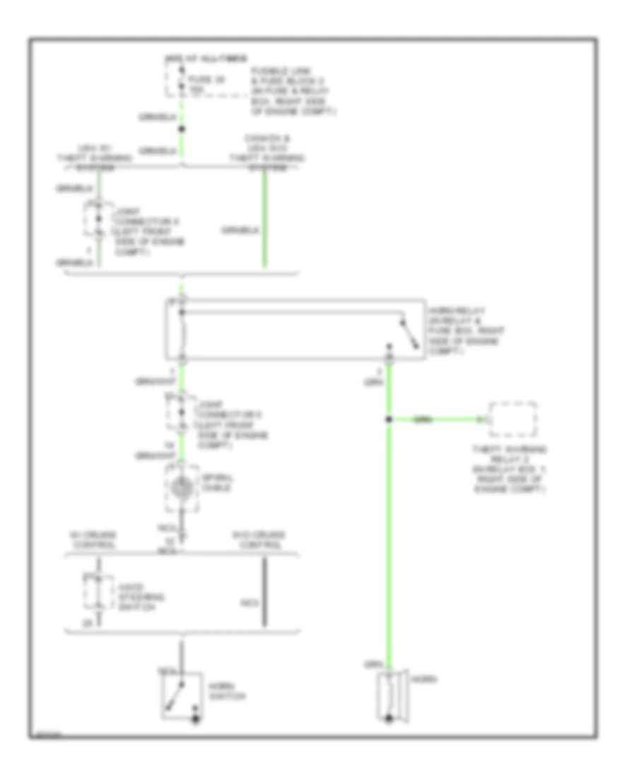
Horn Wiring Diagram for Nissan Altima GXE 1997
List of elements for Horn Wiring Diagram for Nissan Altima GXE 1997:
- Ascd steering switch
- Canada & usa w/o theft warning system
- Fuse 35 10a
- Fusible link & fuse block 2 (in fuse & relay box, right side of engine compt)
- Horn
- Horn relay (in relay & fuse box, right side of engine compt)
- Horn switch
- Hot at all times
- Joint connector 5 (left front side of engine compt)
- Joint connector 6 (left front side of engine compt)
- Nca
- Spiral cable
- Theft warning relay 2 (in relay box 1, right side of engine compt)
- Usa w/ theft warning system
- W/ cruise control
- W/o cruise control
INSTRUMENT CLUSTER
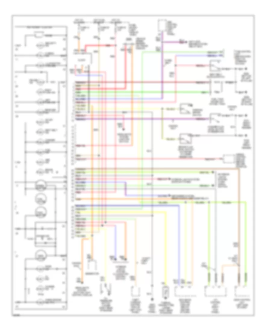
Instrument Cluster Wiring Diagram for Nissan Altima GXE 1997
List of elements for Instrument Cluster Wiring Diagram for Nissan Altima GXE 1997:
- (mil)
- A/t control unit (right kick panel)
- A/t only
- A/t w/ ascd only
- Abs control module (left kick panel)
- Abs ind
- Air bag ind
- Airbag control module (behind center console)
- Anti-lock brakes system (relay box)
- Ascd control unit (left side of dash)
- Bat
- Brake fluid level switch (in master cylinder reservoir)
- Brake ind
- Canada only
- Charge ind
- Check engine ind
- Chime
- Clock
- Cruise ind
- Defoggers system (rear window defogger relay)
- Door ind
- Ecm (eccs control module) (below center of dash)
- Exterior lights system (turn signal switch)
- Fuel gauge
- Fuel ind
- Fuel tank gauge unit (in fuel tank)
- Fuse 12 10a
- Fuse 20 10a
- Fuse 25 10a
- Fuse block (left side of dash)
- G100 (left front fender)
- G101 (right front fender)
- G203 (right kick panel)
- G305 (bottom of right "b" pillar)
- G308 (bottom of left "b" pillar)
- Generator
- Gnd
- Headlights system (daytime light control module)
- Headlights system (lighting switch)
- Hi beam ind
- Hot at all times
- Hot in on or start
- Ign
- Illumination (4 bulbs)
- Instrument cluster
- Interior lights system (door switches)
- Interior lights system (illumination control switch)
- Left turn ind
- Od off ind
- Oil ind
- Oil pressure switch (lower right rear of engine)
- Parking brake switch
- Rear def. ind
- Red
- Right turn ind
- Seat belt buckle switch
- Seat belt ind
- Security ind
- Speed- ometer
- Tach- ometer
- Temp. gauge
- Theft only
- Theft warning control module (left kick panel)
- Thermal transmitter (upper right rear of engine)
- Time control unit (behind dash, right of steering column)
- Vehicle speed sensor (on trans- mission)
- W/abs only
- W/anti-
- Washer fluid level switch (in reservoir)
- Washer ind
INTERIOR LIGHTS
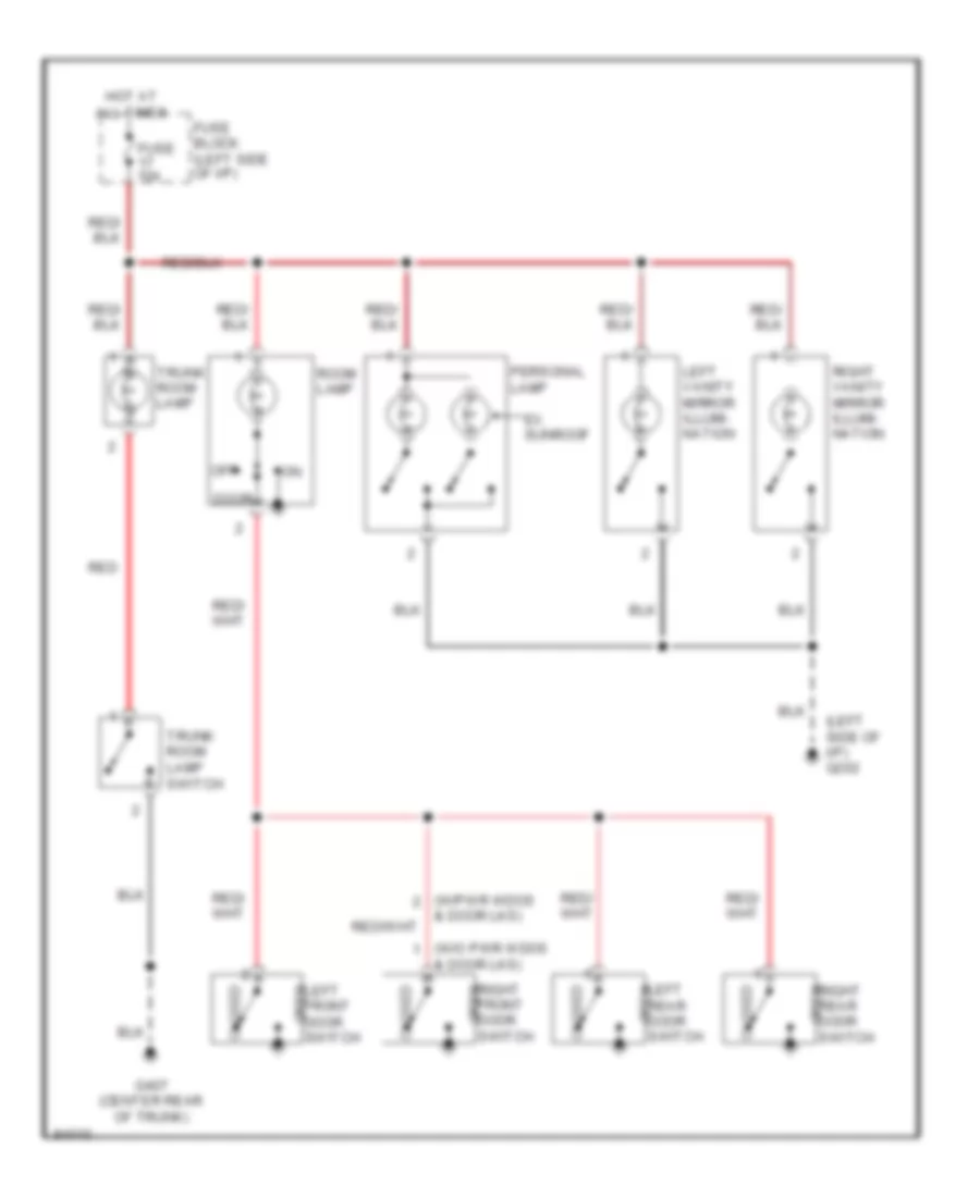
Courtesy Lamps Wiring Diagram for Nissan Altima GXE 1997
List of elements for Courtesy Lamps Wiring Diagram for Nissan Altima GXE 1997:
- (left side of i/p) g202
- (w/o pwr wdos & door lks)
- (w/pwr wdos & door lks)
- Closed
- Door
- Ex. sunroof
- Fuse 10a
- Fuse block (left side of i/p)
- G407 (center rear of trunk)
- Hot at all times
- Left front door switch
- Left rear door switch
- Left vanity mirror illumi- nation
- Off
- Open
- Personal lamp
- Red
- Right front door switch
- Right rear door switch
- Right vanity mirror illumi- nation
- Room lamp
- Trunk room lamp
- Trunk room lamp switch
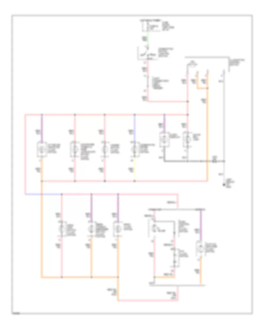
Instrument Illumination Wiring Diagram for Nissan Altima GXE 1997
List of elements for Instrument Illumination Wiring Diagram for Nissan Altima GXE 1997:
- (left side of i/p) g202
- 1st
- 2nd
- A/t device indicator (illumi- nation)
- Ascd main switch (illumi- nation)
- Auto a/c
- Auto a/c amplifier (illumi- nation)
- Bulbs
- Clock (display)
- Combination meter (illumi- nation)
- Combination switch (lighting switch)
- Fuse 23 15a
- Fuse block (left side of i/p)
- Glove box lamp
- Hazard switch (illumi- nation)
- Hot at all times
- Ill
- Illumination control switch
- Joint connector 6 (left front fender)
- Main power window & door lock/unlock switch (illumi- nation)
- Manual a/c
- Nca
- Off
- Ptc (illumi- nation)
- Push control unit (illumi- nation)
- Radio (illumi- nation)
- Rear window defogger switch (illumi- nation)
POWER ANTENNA
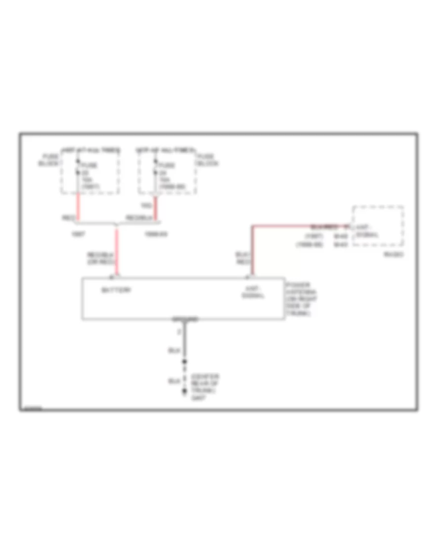
Power Antenna Wiring Diagram for Nissan Altima GXE 1997
List of elements for Power Antenna Wiring Diagram for Nissan Altima GXE 1997:
- (1997)
- (1998-99)
- (center rear of trunk) g407
- 10q
- 1998-99
- Ant- signal
- Battery
- Fuse 10a (1997)
- Fuse 10a (1998-99)
- Fuse block
- Ground
- Hot at all times
- M-40
- M-48
- Power antenna (on right side of trunk)
- Radio
- Red
POWER DISTRIBUTION
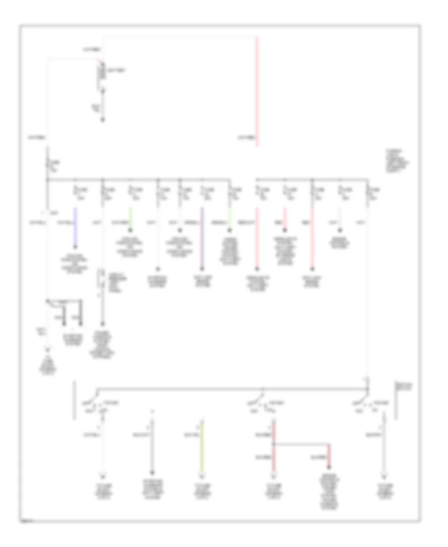
Power Distribution Wiring Diagram (1 of 2) for Nissan Altima GXE 1997
List of elements for Power Distribution Wiring Diagram (1 of 2) for Nissan Altima GXE 1997:
- Acc
- Anti-lock brake system
- Battery
- Circuit breaker (left kick panel)
- Cooling fans system, air conditioning system
- E-47
- Engine controls system
- Engine controls system, power tops system, power windows system
- Fuse 10a
- Fuse 15a
- Fuse 20a
- Fuse a 30a
- Fuse b 30a
- Fuse c 25a
- Fuse e 75a
- Fuse f 30a
- Fuse g 25a
- Fuse h 30a
- Fusible link & fuse box (left front of engine compt.)
- Headlights system, anti-theft system
- Headlights system, anti-theft system, exterior lights system
- Horns system, cruise control system, anti-theft system
- Ignition switch
- Nca
- Off
- Power windows system, door locks & power tops systems
- Red
- Start
- Starting/ charging system
- Starting/ charging system & anti-theft system
- To fuse block (diagram 2 of 2)
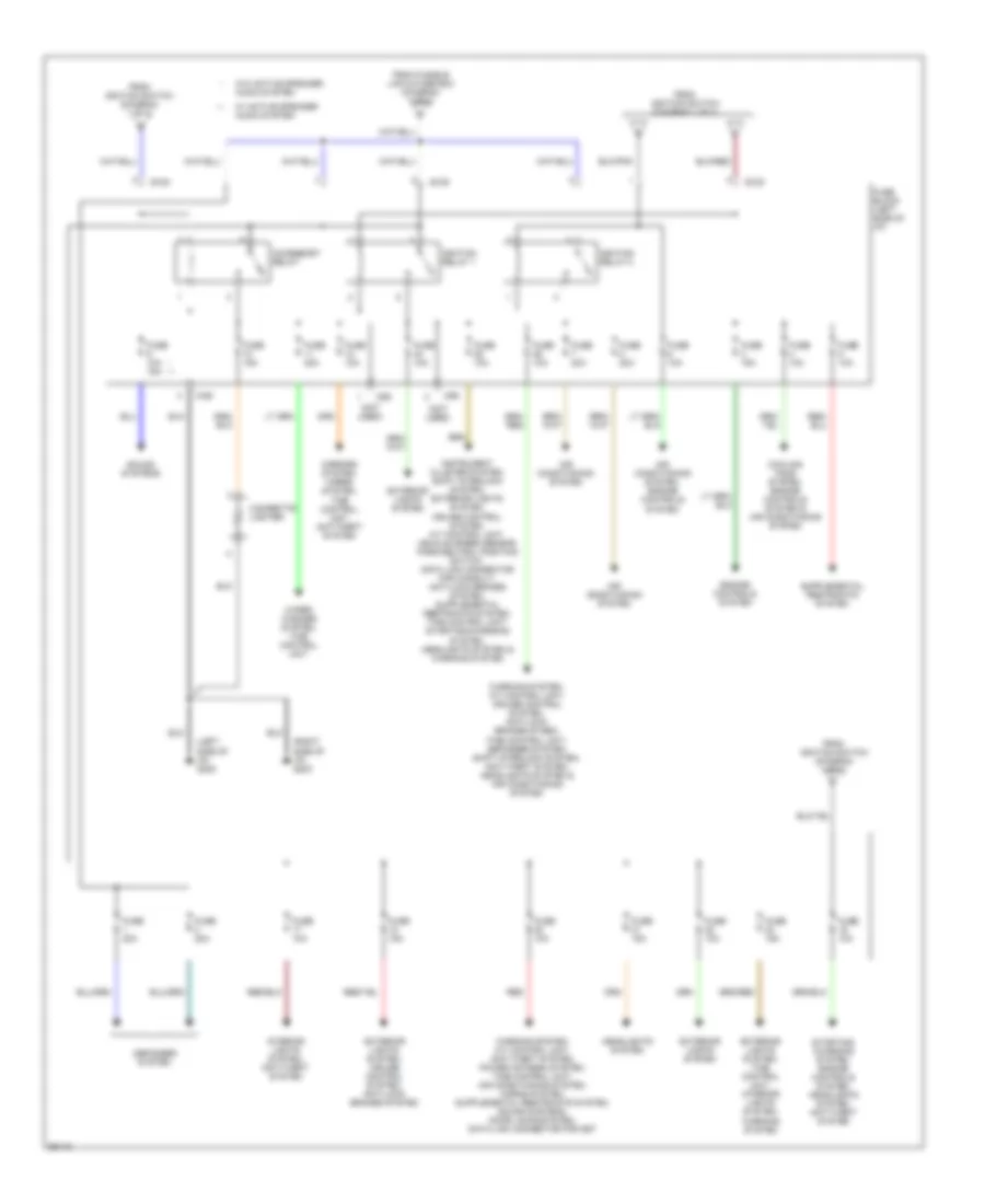
Power Distribution Wiring Diagram (2 of 2) for Nissan Altima GXE 1997
List of elements for Power Distribution Wiring Diagram (2 of 2) for Nissan Altima GXE 1997:
- (left side of i/p) g202
- (not used)
- (right side of i/p) g203
- * **
- Accessory relay
- Air conditioning system
- Air conditioning system, engine controls system
- Cigarette lighter
- Cooling fans system, engine controls system & air conditioning system
- Defogger system
- E108
- E109
- Engine controls system
- Exterior lights system
- Exterior lights system, cruise control system, anti-lock brakes system
- Exterior lights system, time control unit, interior lights system, warning system
- From fusible link & fuse box (diagram 1 of 2)
- From ignition switch (diagram 1 of 2)
- Fuse 10a
- Fuse 10a 15a
- Fuse 15a
- Fuse 20a
- Fuse block (left side of i/p)
- Headlights system
- Ignition relay 1
- Ignition relay 2
- Interior lights system, anti-theft system
- M-86
- M86
- Mirrors system, horns system, time control unit, anti-theft system
- Red
- Sound systems
- Starting/ charging system, engine controls system, headlights system, anti-theft system
- W/ active speaker audio system
- W/o active speaker audio system
- Warning system, a/t control unit, cruise control system, anti-lock brakes sysem, time control unit, defogger system, shift interlock system, anti-theft system, headlights system & air conditioning system
- Wiper/ washer system, time control unit
POWER DOOR LOCKS
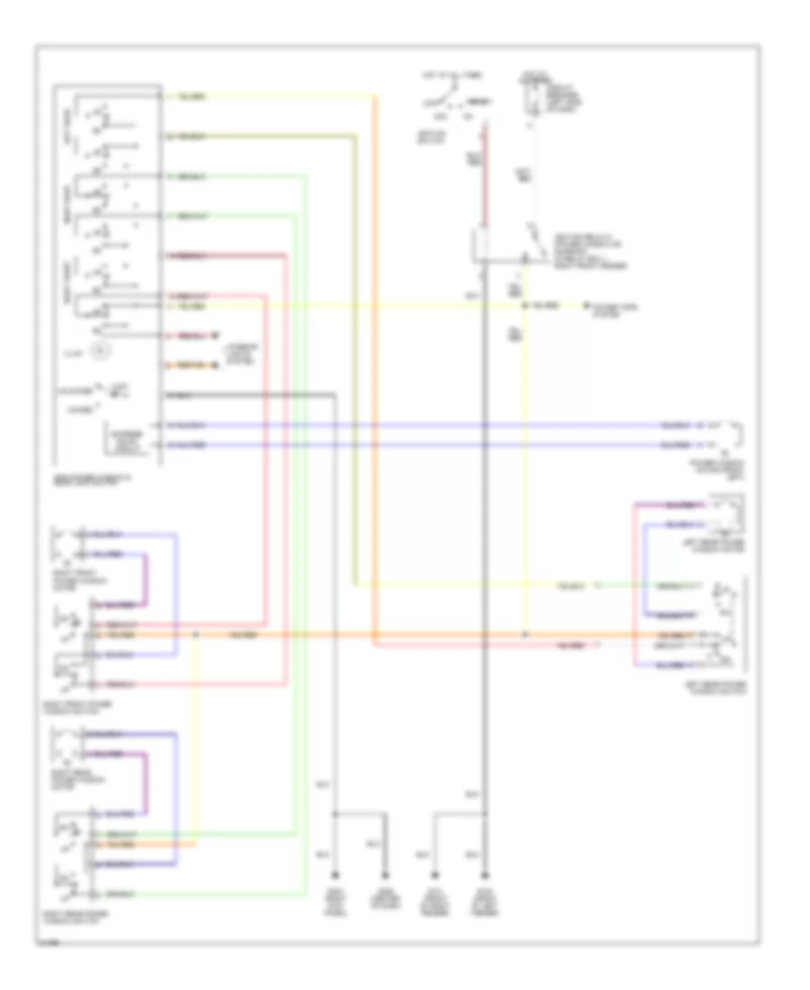
Power Door Lock Wiring Diagram for Nissan Altima GXE 1997
List of elements for Power Door Lock Wiring Diagram for Nissan Altima GXE 1997:
- Battery
- Between full stroke and n
- Circuit breaker (left side of dash)
- Closed
- Cylinder switch
- Door key
- Door lock control unit (behind left side of dash)
- Door switch
- Full stroke unlock switch
- Fuse 10a
- Fuse g 25a
- Fusible link & fuse box (left front of engine compartment, near battery)
- G203 (right kick panel)
- G206 (center of dash)
- G305 (right "b" pillar)
- G308 (left "b" pillar)
- Ground
- Hot at all times
- Instrument cluster system
- Key switch
- Left front door key cylinder switch
- Left front door lock actuator
- Left front door switch
- Left rear door lock actuator
- Lock
- Lock/ unlock output
- Main power window and door lock switch
- Open
- Power tops system
- Red
- Right front door key cylinder switch
- Right front door lock actuator
- Right front door switch
- Right rear door lock actuator
- Unlock
- Unlock sensor
- W/ theft warning system
- W/o theft warning system
POWER MIRRORS
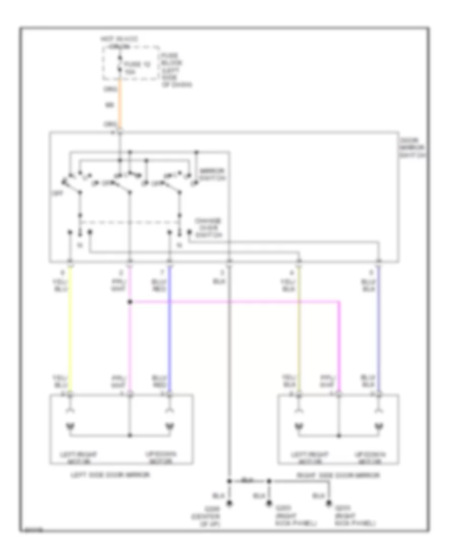
Power Mirror Wiring Diagram for Nissan Altima GXE 1997
List of elements for Power Mirror Wiring Diagram for Nissan Altima GXE 1997:
- Change over switch
- Door mirror switch
- Fuse 12 10a
- Fuse block (left side of dash)
- G203 (right kick panel)
- G206 (center of i/p)
- Hot in acc or on
- Left side door mirror
- Left/right motor
- Mirror switch
- Off
- Right side door mirror
- Up/down motor
POWER TOP/SUNROOF
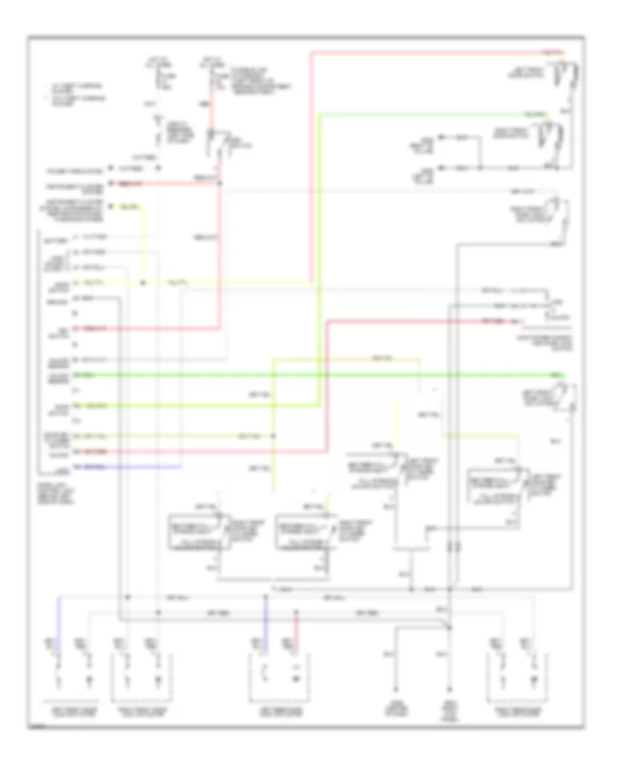
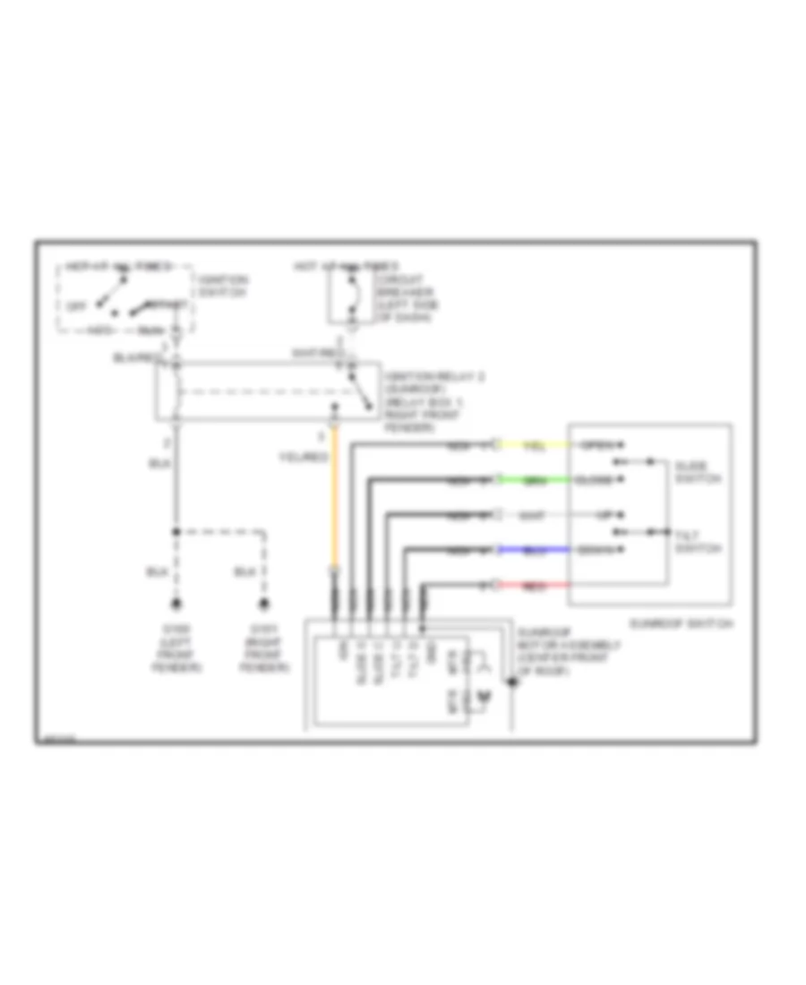
Power Top/Sunroof Wiring Diagrams for Nissan Altima GXE 1997
List of elements for Power Top/Sunroof Wiring Diagrams for Nissan Altima GXE 1997:
- Acc
- Circuit breaker (left side of dash)
- Close
- Down
- G100 (left front fender)
- G101 (right front fender)
- Gnd
- Hot at all times
- Ign
- Ignition relay 2 (sunroof) (relay box 1, right front fender)
- Ignition switch
- Mtr (+)(-)
- Nca
- Off
- Open
- Red
- Run
- Slide c
- Slide o
- Slide switch
- Start
- Sunroof motor assembly (center front of roof)
- Sunroof switch
- Tilt d
- Tilt switch
- Tilt u
POWER WINDOWS
Power Window Wiring Diagram for Nissan Altima GXE 1997
List of elements for Power Window Wiring Diagram for Nissan Altima GXE 1997:
- Acc
- Circuit breaker (left side of dash)
- Express down circuit
- G100 (front of left fender)
- G101 (front of right fender)
- G203 (right kick panel)
- G206 (center of dash)
- Hot at all times
- Ignition relay-2 (power window or sunroof) (in relay box 1, right front fender)
- Ignition switch
- Illum
- Interior lights system
- Left rear
- Left rear power window motor
- Left rear power window switch
- Lock
- Lock sw
- Locked
- Main power window & door lock switch
- Power tops system
- Power window motor (front left)
- Right front
- Right front power window motor
- Right front power window switch
- Right rear
- Right rear power window motor
- Right rear power window switch
- Start
- Unlocked
RADIO
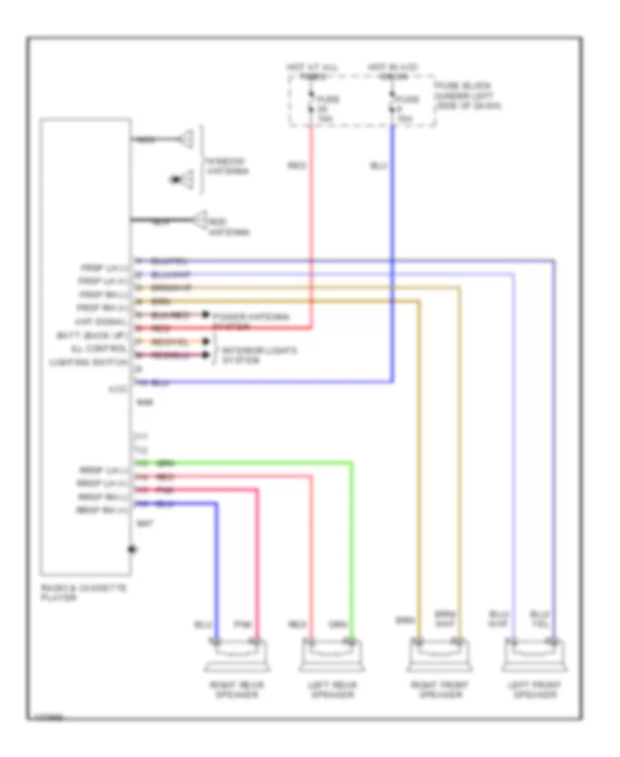
Radio Wiring Diagrams, Base Radio for Nissan Altima GXE 1997
List of elements for Radio Wiring Diagrams, Base Radio for Nissan Altima GXE 1997:
- Acc
- Ant-signal
- Batt (back up)
- Frsp lh (+)
- Frsp lh (-)
- Frsp rh (+)
- Frsp rh (-)
- Fuse 10a
- Fuse block (under left side of dash)
- Hot at all times
- Hot in acc or on
- Ill control
- Interior lights system
- Left front speaker
- Left rear speaker
- Lighting switch
- M47
- M48
- Nca
- Pnk
- Power antenna system
- Radio & cassette player
- Red
- Right front speaker
- Right rear speaker
- Rod antenna
- Rrsp lh (+)
- Rrsp lh (-)
- Rrsp rh (+)
- Rrsp rh (-)
- Window antenna
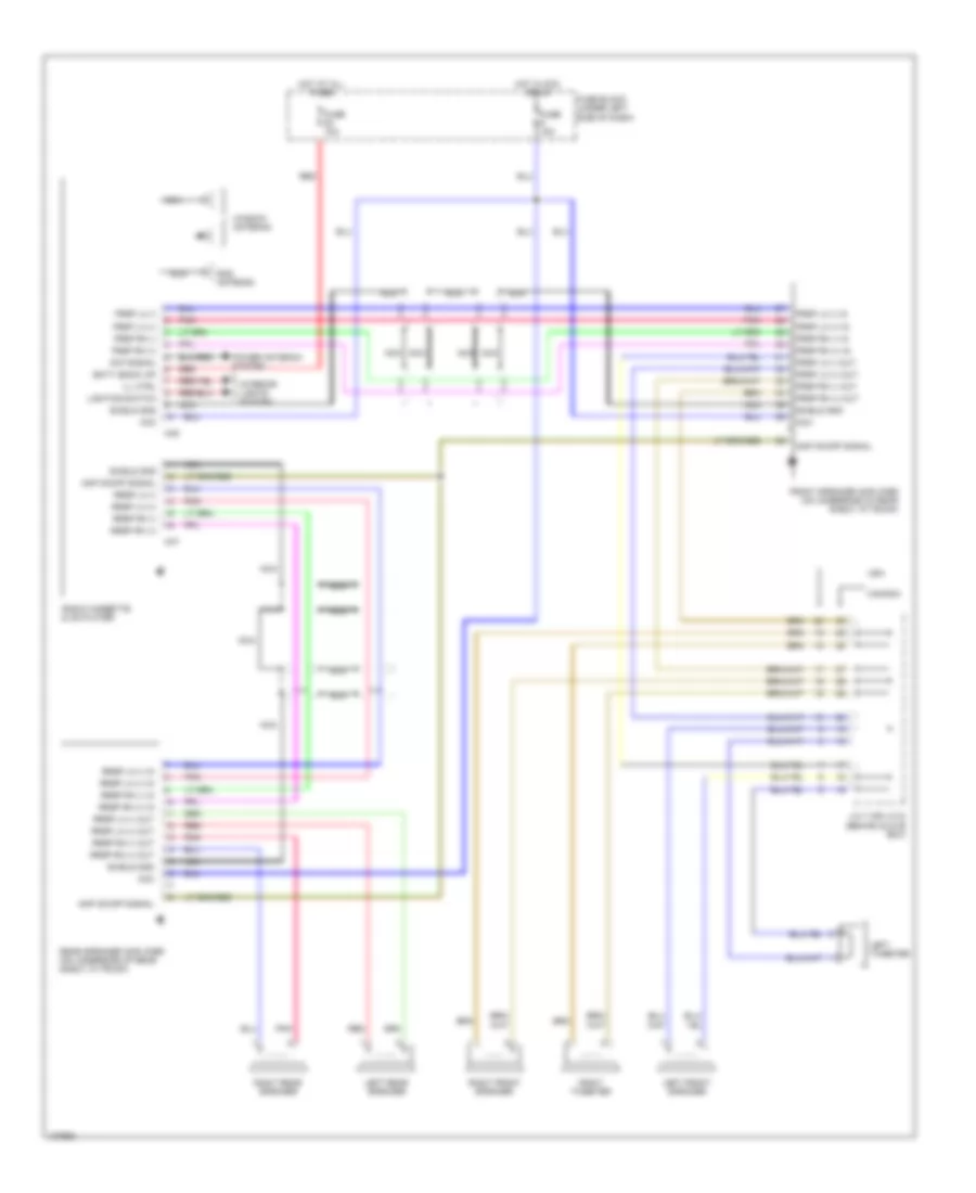
Radio Wiring Diagrams, Premium Radio for Nissan Altima GXE 1997
List of elements for Radio Wiring Diagrams, Premium Radio for Nissan Altima GXE 1997:
- Acc
- Amp on/0ff signal
- Amp on/off signal
- Ant-signal
- Batt (back up)
- Canada
- Front speaker amplifier (on underside of rear shelf, in trunk)
- Frsp lh (+)
- Frsp lh (+) in
- Frsp lh (+) out
- Frsp lh (-)
- Frsp lh (-) in
- Frsp lh (-) out
- Frsp rh (+)
- Frsp rh (+) in
- Frsp rh (+) out
- Frsp rh (-)
- Frsp rh (-) in
- Frsp rh (-) out
- Fuse 10a
- Fuse 15a
- Fuse block (under left side of dash)
- Hot at all times
- Hot in acc or on
- Ill ctrl
- Interior lights system
- J/c 7 (or j/c 8) (behind glove box)
- Left front speaker
- Left rear speaker
- Left tweeter
- Lighting switch
- M47
- M48
- Nca
- Pnk
- Power antenna system
- Radio cassette & cd player
- Rear speaker amplifier (on underside of rear shelf, in trunk)
- Red
- Right front speaker
- Right rear speaker
- Right tweeter
- Rod antenna
- Rrsp lh (+)
- Rrsp lh (+) in
- Rrsp lh (+) out
- Rrsp lh (-)
- Rrsp lh (-) in
- Rrsp lh (-) out
- Rrsp rh (+)
- Rrsp rh (+) in
- Rrsp rh (+) out
- Rrsp rh (-)
- Rrsp rh (-) in
- Rrsp rh (-) out
- Shield gnd
- Usa
- Window antenna
SHIFT INTERLOCKS
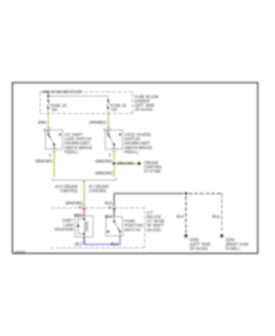
Shift Interlock Wiring Diagram for Nissan Altima GXE 1997
List of elements for Shift Interlock Wiring Diagram for Nissan Altima GXE 1997:
- A/t device (at base of shift lever)
- A/t shift lock switch (on bracket, above brake pedal)
- Ascd cancel switch (on bracket, above brake pedal)
- Cruise control system
- Fuse 25 10a
- Fuse 26 10a
- Fuse block (under left side of dash)
- G202 (left side of dash)
- G203 (right kick panel)
- Hot in on or start
- Park position switch
- Red
- Shift lock solenoid
- W/ cruise control
- W/o cruise control
STARTING/CHARGING
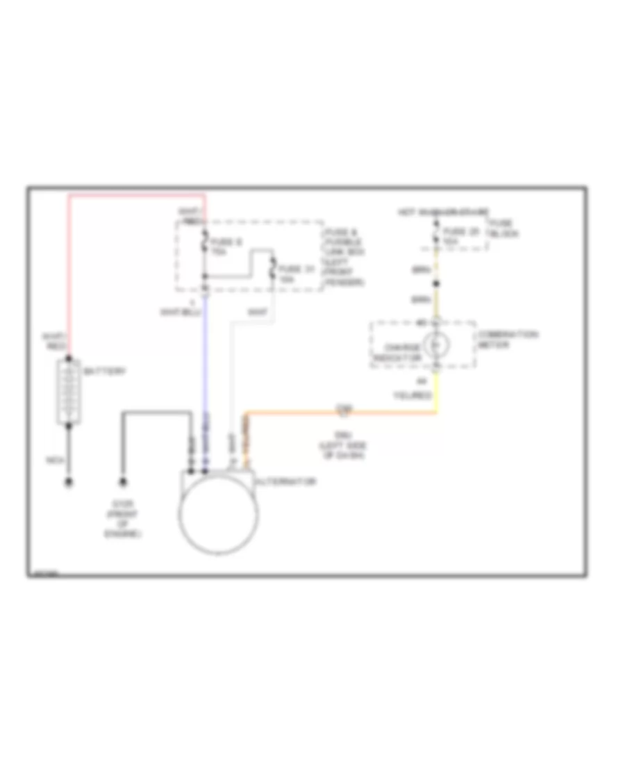
Charging Wiring Diagram for Nissan Altima GXE 1997
List of elements for Charging Wiring Diagram for Nissan Altima GXE 1997:
- Alternator
- Battery
- C10
- Charge indicator
- Combination meter
- Fuse & fusible link box (left front fender)
- Fuse 25 10a
- Fuse 31 10a
- Fuse block
- Fuse e 75a
- G125 (front of engine)
- Hot in on or start
- Nca
- Smj (left side of dash)
Starting Wiring Diagram for Nissan Altima GXE 1997
List of elements for Starting Wiring Diagram for Nissan Altima GXE 1997:
- 1995 m/t canada
- 1995 m/t usa 1996, 1997 m/t all
- A/t
- Acc
- Battery
- Clutch interlock relay (left front of engine compartment)
- Clutch pedal position switch (near clutch pedal)
- Fuse 16 10a
- Fuse b 30a
- Fuse block
- Fusible link and fuse box (right front shock tower)
- G203 (right kick panel)
- Ignition switch
- Inhibitor switch (on transmission)
- M/t only
- Nca
- Off
- Start
- Starter motor
- Theft warning relay 1 (right front shock tower)
- W/ anti- theft
- W/o anti- theft
SUPPLEMENTAL RESTRAINTS
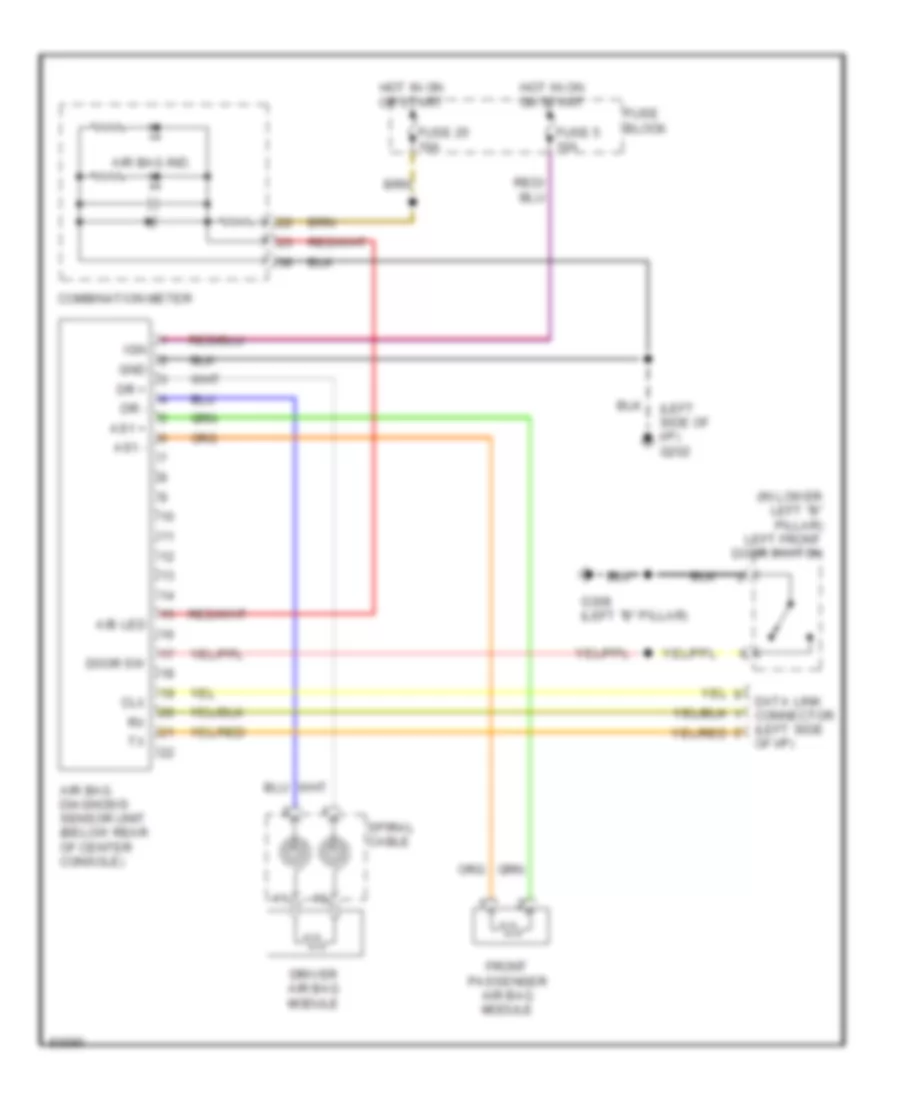
Supplemental Restraint Wiring Diagram for Nissan Altima GXE 1997
List of elements for Supplemental Restraint Wiring Diagram for Nissan Altima GXE 1997:
- (in lower left "b" pillar) left front door switch
- (left side of i/p) g202
- A/b led
- Air bag diagnosis sensor unit (below rear of center console)
- Air bag ind.
- As1 +
- As1 -
- Clx
- Combination meter
- Data link connector (left side of i/p)
- Door sw
- Dr +
- Dr -
- Driver air bag module
- Front passenger air bag module
- Fuse 25 10a
- Fuse 5 10a
- Fuse block
- G308 (left "b" pillar)
- Gnd
- Hot in on or start
- Ign
- Spiral cable
TRANSMISSION
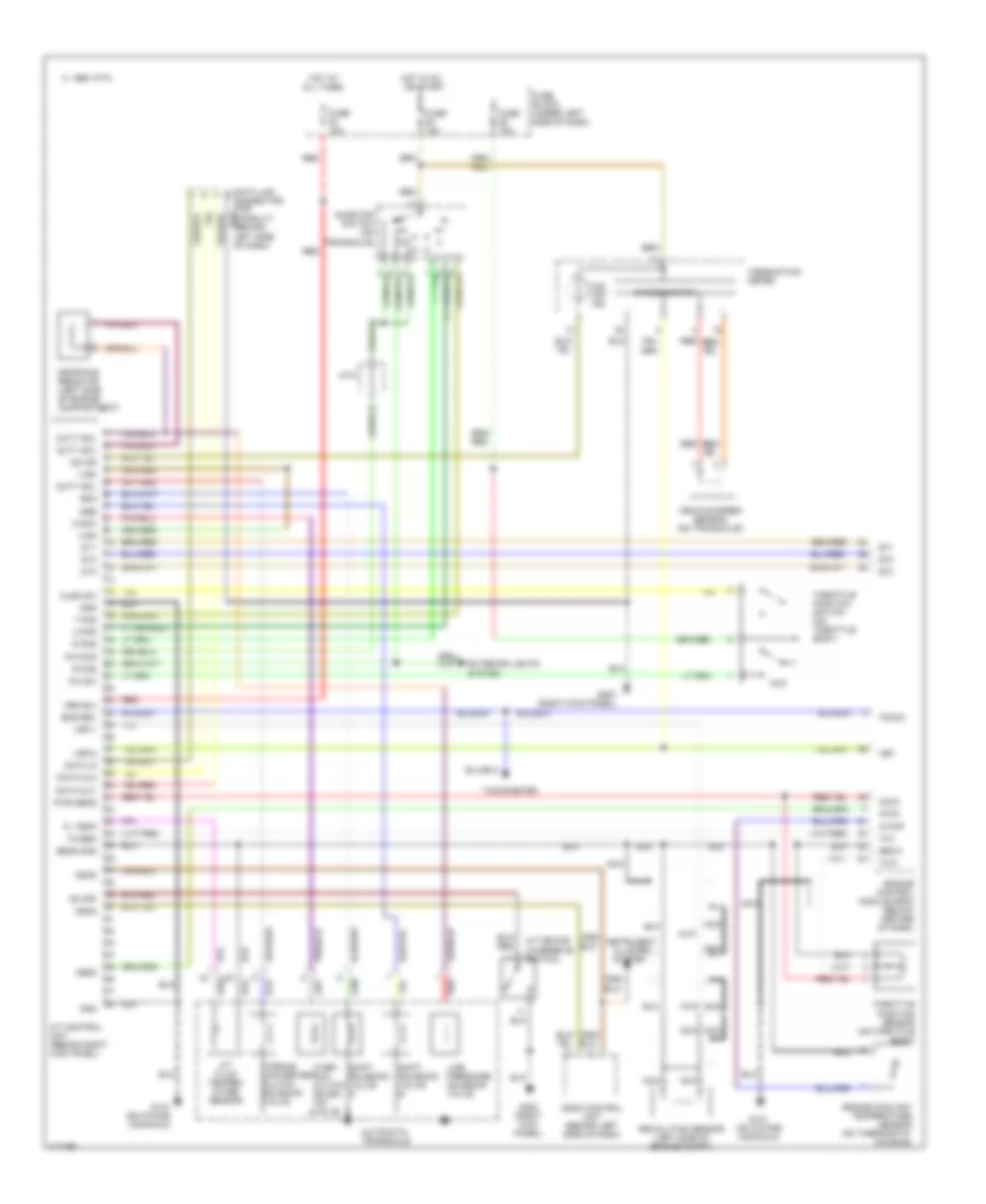
A/T Wiring Diagram for Nissan Altima GXE 1997
List of elements for A/T Wiring Diagram for Nissan Altima GXE 1997:
- 1 pos
- 1995 vftc c
- 2 pos
- A/t control unit (behind right kick panel)
- A/t device (overdrive switch)
- A/t fluid temper- ature sensor
- All times
- Ascd
- Ascd control unit (behind left side of dash)
- Atck
- Automatic transaxle
- Avcc
- Clsd sw
- Cluster system
- Combination meter
- D pos
- Data clk
- Data in
- Data link connector (for consult) (behind left side of dash)
- Data out
- Dropping resistor (left side of engine compartment)
- Dt1
- Dt2
- Dt3
- Duty sol
- Eng rev
- Engine control module (ecm) (below center of dash)
- Engine coolant temperature sensor (on thermostat housing)
- Exterior lights system
- Fl temp
- Fuse 10a
- Fuse block (under left side of dash)
- G131 (on intake manifold)
- G203 (right kick panel)
- Gnd
- Gnd-a
- Hot at
- Hot in on or start
- Inhibitor switch (on transaxle)
- Instrument
- J/c 5
- Line pressure solenoid valve
- Mem b/u
- Nca
- O/d off ind
- Obd2
- Od ind
- Od off
- Over- run clutch solen- oid valve
- Ovr/c
- P/n pos
- Pwr sens
- R pos
- Red
- Revolution sensor (left side of engine compt)
- Sens gnd
- Shift solenoid valve a
- Shift solenoid valve b
- Speedometer
- Ssa
- Ssb
- Tacho
- Tachometer
- Th/sen
- Throttle position sensor (on throttle body)
- Throttle position switch (on throttle body)
- Torque converter clutch solenoid valve
- Tvo
- Tvo1
- Vehicle speed sensor (on transaxle)
- Vign
- Vsp
- Vsp-1
- Vsp-2
- W/tmp
- Wo sw
- Wot
WARNING SYSTEMS
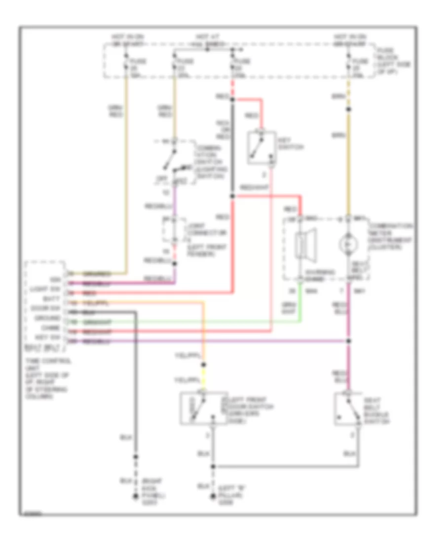
Warning System Wiring Diagrams for Nissan Altima GXE 1997
List of elements for Warning System Wiring Diagrams for Nissan Altima GXE 1997:
- (left "b" pillar) g308
- (right kick panel) g203
- 1st
- 2nd
- Batt
- Chime
- Closed
- Combin- ation switch (lighting switch)
- Combination meter (instrument cluster)
- Door sw
- Fuse 10a
- Fuse 15a
- Fuse block (left side of i/p)
- Ground
- Hot at all times
- Hot in on or start
- Ign
- Joint connector (left front fender)
- Key sw
- Key switch
- Left front door switch (driver's side)
- Light sw
- M41
- M43
- M44
- Nca or red
- Off
- Open
- Red
- Seat belt
- Seat belt buckle switch
- Seat belt ind.
- Time control unit (left side of i/p, right of steering column)
- Warning chime
WIPER/WASHER
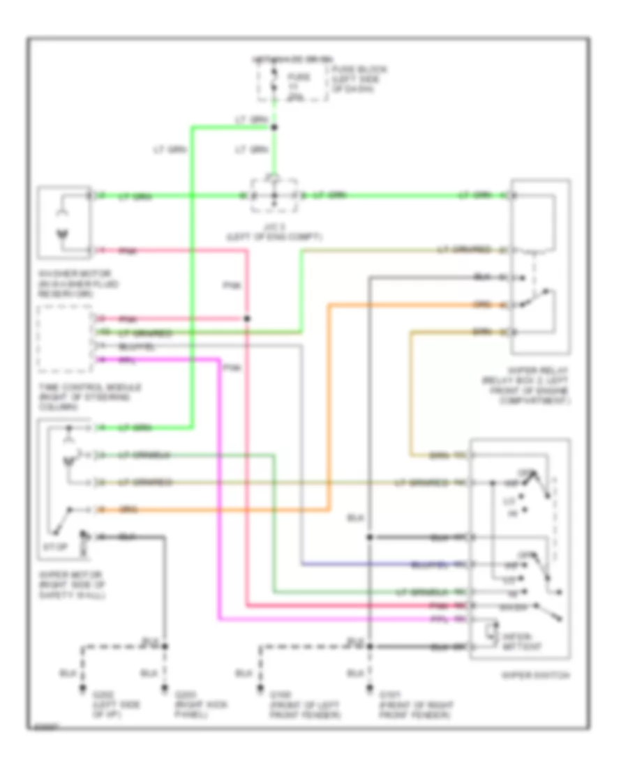
Wiper/Washer Wiring Diagram for Nissan Altima GXE 1997
List of elements for Wiper/Washer Wiring Diagram for Nissan Altima GXE 1997:
- Fuse 20a
- Fuse block (left side of dash)
- G100 (front of left front fender)
- G101 (front of right front fender)
- G202 (left side of i/p)
- G203 (right kick panel)
- Hot in acc or on
- Int
- Inter- mittent
- J/c 3 (left of eng compt)
- Move
- Off
- Pnk
- Stop
- Time control module (right of steering column)
- Wash
- Washer motor (in washer fluid reservoir)
- Wiper motor (right side of safety wall)
- Wiper relay (relay box 2, left front of engine compartment)
- Wiper switch

 Čeština
 Dansk
Dansk Deutsch
 Ελληνικά
 English
 English
 Español
 Suomi
Suomi Français
 עברית
עברית Hrvatski
 Magyar
 Italiano
 日本語
日本語 한국어
한국어 Nederlands
 Polski
 Português
 Português
 Română
 Русский
 Slovenčina
 Slovenščina
 Svenska
 Türkçe
 中文 (中国)