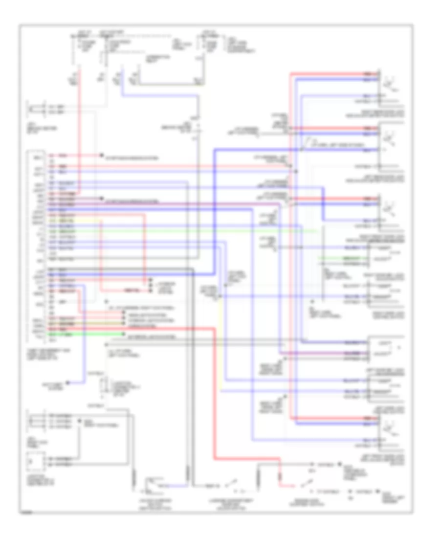
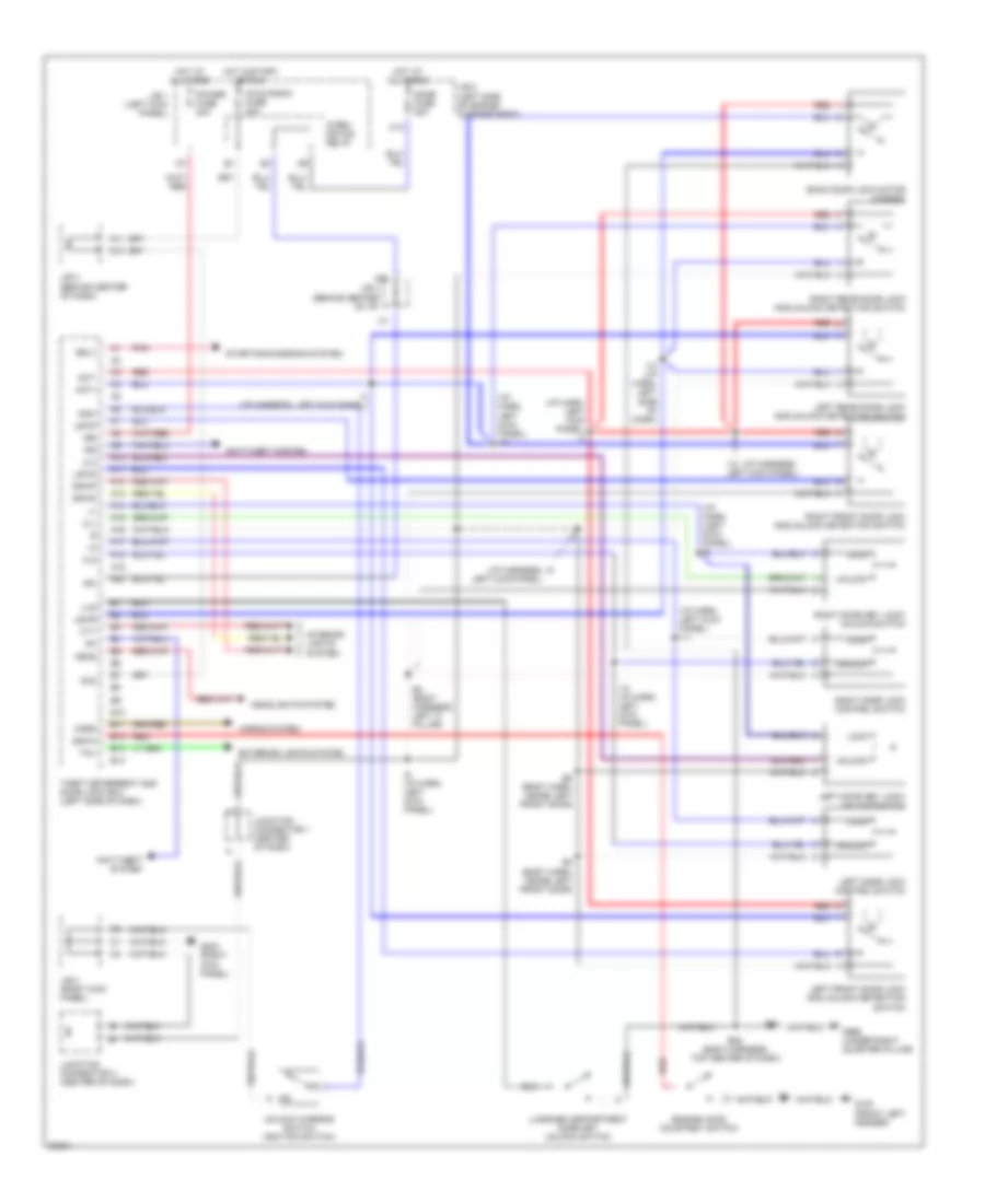
AIR CONDITIONING
A/C Wiring Diagram for Toyota Corolla 1996
 https://portal-diagnostov.com/license.html
Automotive Electricians Portal FZCO
Automotive Electricians Portal FZCO
https://portal-diagnostov.com/license.html
https://portal-diagnostov.com/license.html
Automotive Electricians Portal FZCO
Automotive Electricians Portal FZCO
List of elements for A/C Wiring Diagram for Toyota Corolla 1996:
- (1995 1.8l a/t, all 1996) (1995 1.8l m/t & 1.6l)
- (1996) (1995)
- (left front of engine compt)
- 1994 vftc c
- A/c amplifier (right side of i/p)
- A/c condenser fan motor (right front of engine compt)
- A/c condenser fan relay n0. 3
- A/c condenser fan relay no. 2
- A/c dual pressure switch (right rear of engine compt)
- A/c fuse
- A/c high pressure switch (left front of engine compt)
- A/c magnet clutch (right front of engine)
- A/c switch
- A/c thermistor (right side of i/p)
- A17
- Blower motor (right side of i/p)
- Blower resistor (right side of i/p)
- C14
- Cds fuse 30a
- D11
- Ecu-ig fuse 15a
- Engine control module (right side of i/p)
- Fan fusible link 30a
- G100 (front left fender)
- G203 (right kick panel)
- Gauge fuse 10a
- Heater blower switch
- Heater fuse 40a
- Heater relay
- Hot at all times
- Hot in on or start
- Hot in run or start
- Integration relay
- Interior lights system
- J/b 1 (left kick panel)
- J/b 1 (left side of i/p)
- J/b 2
- J/b 2 (left side of engine compt)
- J/b 3 (center of i/p)
- J/b 4 (right kick panel)
- Magnet clutch relay
- Off
- R/b 5 (left side of engine compt)
- Radiator fan motor
- Radiator fan relay no. 1
- Red
- Water temperature switch (right radiator support)
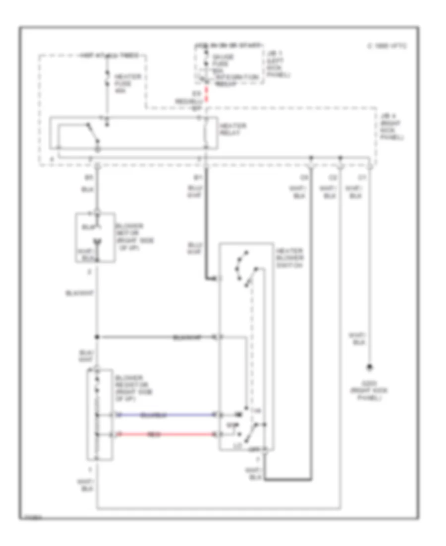
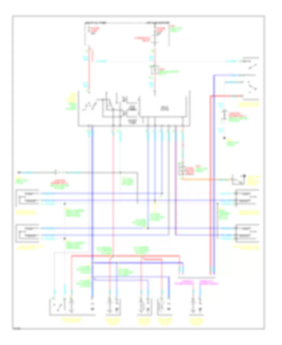
Heater Wiring Diagram for Toyota Corolla 1996
List of elements for Heater Wiring Diagram for Toyota Corolla 1996:
- (right side
- Blower motor
- Blower resistor (right side of i/p)
- C 1995 vftc
- G203 (right kick panel)
- Gauge fuse 10a integration relay
- Heater blower switch
- Heater fuse 40a
- Heater relay
- Hot at all times
- Hot in on or start
- J/b 1 (left kick panel)
- J/b 4 (right kick panel)
- Of i/p)
- Off
- Red
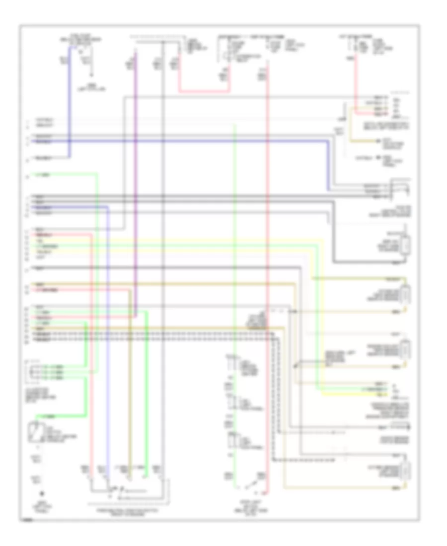
ANTI-LOCK BRAKES
Anti-lock Brake Wiring Diagrams for Toyota Corolla 1996
List of elements for Anti-lock Brake Wiring Diagrams for Toyota Corolla 1996:
- (1996)
- (1995)
- (body harn, left kick panel)
- (eng harn, front of eng compt, above grille)
- (eng harn, right fender apron)
- (i/p harn, behind comb- ination meter)
- (i/p harn, lower left side of dash)
- (i/p harn, lower left side of dash) i3
- A10
- A11
- A12
- Abs actuator (left front corner of eng compt)
- Abs ecu (above left kick panel)
- Abs fuse 50a
- Abs relay (left front of eng compt)
- Abs warning ind
- Ast
- B10
- B11
- B12
- B13
- B14
- B15
- B16
- B17
- B18
- B19
- B20
- B21
- B22
- B23
- B24
- B25
- B26
- Bat
- C10
- Combination meter
- Data link connector 1 (left side of eng compt)
- Dome fuse 20a
- E18
- Ecu-ig fuse 15a
- Fl+
- Fl-
- Fr+
- Fr-
- Fss
- Fuse box (left side of eng compt) (left kick panel)
- G100 (left front fender)
- G101 (right front fender)
- G115 (intake manifold)
- G203 (right kick panel)
- Gauge fuse 10a
- Gnd
- Hot at all times
- Hot in on
- I14
- Ig1
- Integration relay
- J/b 1 (left kick panel)
- J/b 2 (left side of eng compt) (1995 only)
- J/b 2 (left side of engine compartment)
- J/b 3 (behind center of i/p)
- J/b 4 (right kick panel)
- J/c 4 (left kick panel)
- Left front abs speed sensor
- Left rear abs speed sensor
- Parking brake switch (1995 only)
- Pkb
- Pnk
- Red
- Right front abs speed sensor
- Right rear abs speed sensor
- Rl+
- Rl-
- Rr+
- Rr-
- Rssr
- Sflh
- Sflr
- Sfrh
- Sfrr
- Shield
- Srlh
- Srlr
- Srrh
- Srrr
- Stop fuse 15a
- Stop light switch
- Stp
ANTI-THEFT
Anti-theft Wiring Diagram for Toyota Corolla 1996
List of elements for Anti-theft Wiring Diagram for Toyota Corolla 1996:
- (engine harness, front of engine compt above grille opening) e2
- (i/p harn, left end of dash) i9
- (i/p harn, left kick panel) i10
- (i/p harn, left kick panel) i11
- (i/p harn, left side of dash) i13
- +b1
- +b2
- A10
- A11
- A12
- A13
- A14
- A15
- A16
- A17
- A18
- A19
- A20
- A22
- Acc
- Act+
- Act-
- B10
- B11
- B12
- B13
- B14
- B29
- Back door lock control motor (wagon)
- C10
- C19
- C20
- Cig & radio fuse 20a
- Combination meter
- Cty
- D10
- Dome fuse 20a
- Door locks system
- Dswd
- Dswh
- Dswl
- Dswp
- Engine hood courtesy switch
- G100 (front of left fender)
- G203 (right kick panel)
- G415 (center of lower back panel)
- Haz-horn fuse 20a
- Head
- Headlights system
- Horn
- Horns system
- Hot at all times
- Hot in start or run
- I10(or i9)
- I40(or i5)
- Ind
- Integration relay
- Interior lights system
- J/b 1 (left kick panel)
- J/b 2 (left side of engine compartment)
- J/b 3 (behind center of i/p)
- J/b 3 (behind combination meter)
- J/b 4 (right kick panel)
- J/c 1 (behind radio)
- J/c 3 (right side of combination meter)
- Ksw
- Left door key lock/ unlock switch
- Left door lock control switch
- Left front door lock motor and unlock detection switch
- Left rear door lock motor and unlock detection switch
- Lock
- Lswd
- Lswp
- Lswr
- Lug
- Luggage compartment door key unlock switch
- Pnk
- Power fuse 30a
- Red
- Right door key lock/ unlock switch
- Right door lock control switch
- Right front door lock motor and unlock detection switch
- Right rear door lock motor and unlock detection switch
- Srly
- Starting/charging system
- Tail
- Taillights system
- Theft deterrent and door lock ecu (left side of i/p)
- Theft deterrent horn
- Theft deterrent ind
- Ul1
- Ul2
- Ul3
- Unlock
- Unlock warning switch (ignition switch)
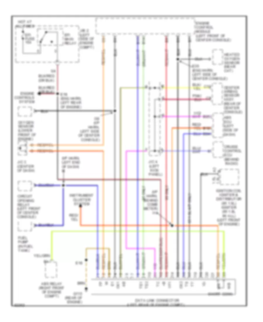
COMPUTER DATA LINES
Computer Data Lines for Toyota Corolla 1996
List of elements for Computer Data Lines for Toyota Corolla 1996:
- (i/p harn, behind comb meter) i14
- (i/p harn, left end of dash) i8
- (left rear of engine compt)
- 1.8l 1.6l
- 95 1.8l a/t only
- 95 only
- Abs ecu (left side of dash)
- Abs relay (right front of engine compt)
- All times
- B14
- B15
- B18
- B24
- B25
- C12
- Center airbag sensor assy. (rear of center console)
- Circuit opening relay (left front of center console)
- Cruise control ecu (behind radio)
- Data link connector
- E18
- E18 (eng harn, left rear of engine)
- E36 (eng harn, left side of center console)
- Efi fuse 15a
- Efi main relay
- Engine control module (left front of center console)
- Fuel pump (in fuel tank)
- G115 (rear of engine)
- Heated oxygen sensor (near cat)
- Hot at
- I36 (i/p harn, left side of center console)
- Ig-
- Ignition coil igniter & distributor (95 1.6l) igniter (95 1.8l 96 all) (left front of engine)
- Instrument cluster system
- J/b 2 (left side of engine compt)
- J/c 3 (center of dash)
- J/c 4 (left kick panel)
- Ox1
- Ox2
- Oxygen sensor (lower front of engine)
- Short conn.
- Te1
- Te2
- Vf1
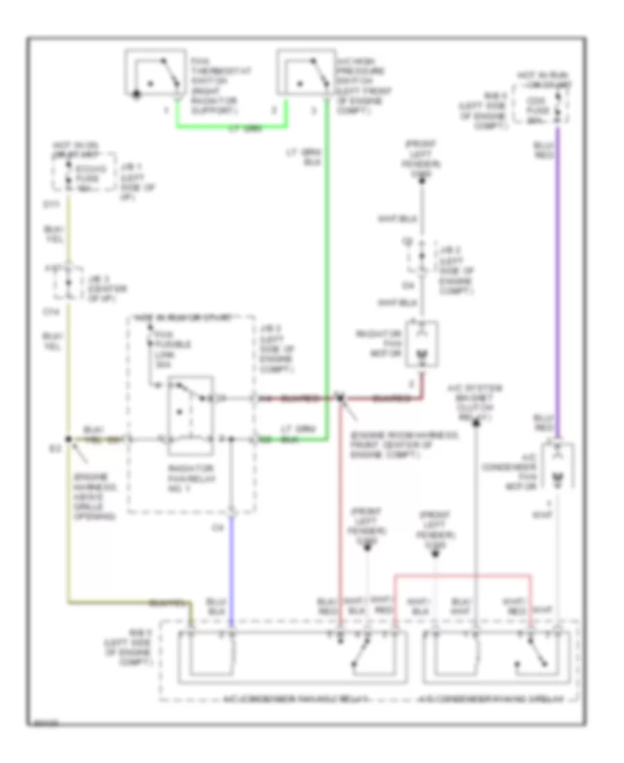
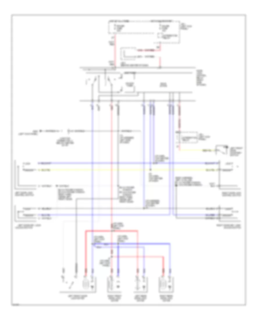
COOLING FAN
Cooling Fan Wiring Diagram for Toyota Corolla 1996
List of elements for Cooling Fan Wiring Diagram for Toyota Corolla 1996:
- (engine harness, above grille opening)
- (engine room harness, front center of engine compt)
- (front left fender) g100
- (left side of engine compt)
- (left side of i/p)
- A/c condenser fan motor
- A/c condenser fan no.2 relay
- A/c condenser fan no.3 relay
- A/c high pressure switch (left front of engine compt)
- A/c system (magnet clutch relay)
- A17
- C14
- Cds fuse 30a
- D11
- Ecu-ig fuse 15a
- Fan fusible link 30a
- Fan thermostat switch (right radiator support)
- Hot in on or start
- Hot in run
- Hot in run or start
- J/b 1
- J/b 2
- J/b 3 (center of i/p)
- Or start
- R/b 5 (left side of engine compt)
- Radiator fan motor
- Radiator fan relay no. 1
CRUISE CONTROL
Cruise Control Wiring Diagram for Toyota Corolla 1996
List of elements for Cruise Control Wiring Diagram for Toyota Corolla 1996:
- (a/t)
- (i/p harness, behind combination meter) i16
- A/t
- A17
- A19
- Batt
- C12
- C15
- Cancel
- Ccs
- Cms
- Cruise control actuator (right side of engine compartment)
- Cruise control clutch switch (left side of dash)
- Cruise control diode (behind instrument cluster)
- Cruise control ecu (center of dash)
- Cruise control ind
- Cruise control switch (combination switch)
- Data link connector 1 (left side of engine compartment)
- E10
- Ect
- Ecu-b fuse 10a
- Ecu-ig fuse 15a
- Engine control module (below center of dash)
- Engine controls system (throttle position sensor)
- G115 (rear of engine)
- G203 (right kick panel)
- Gauge fuse 10a
- Gnd
- Hot at all times
- Hot in on and start
- I25 (i/p harness, left side of radio)
- I32 (i/p harness, left side of center console)
- I7 (i/p harness, left end of dash)
- Idl
- Instrument cluster
- Instrument cluster system (speedometer)
- Integration relay
- J/b 1 (left kick panel)
- J/b 3 (behind center of dash)
- J/b 4 (right kick panel)
- J/c 4 (left kick panel)
- M/t
- Main
- N&c
- Pkb
- Red
- Resume/ accel
- Set/ coast
- Spd
- Starting/charging ststem (clutch start switch)
- Starting/charging system (park/neutral position switch)
- Stop fuse 15a
- Stop light switch (left side of dash)
- Stp+
- Stp-
- Transmissions system (electronically controlled transmission solenoid)
- Vr1
- Vr2
- Vr3
DEFOGGERS
Defogger Wiring Diagram for Toyota Corolla 1996
List of elements for Defogger Wiring Diagram for Toyota Corolla 1996:
- A12
- A13
- A15
- A19
- B1 (body har- ness, left kick panel)
- B24 (body har- ness, behind right rear wheelwell)
- C19
- C20
- Conn e10 (1.8l) conn e7 (1.6l)
- D15
- Defog fuse 30a
- Defog- i/up fuse 7.5a
- Defogger relay
- Diode (for elec idle-up) (1995 only)
- Engine control module (behind center console)
- G200 (left kick panel)
- G203 (right kick panel)
- G410 (right side of hatch door)
- G416 (left rear frame rail)
- G998 (left rear frame rail)
- Gauge fuse 10a
- Hot at all times
- Hot in on or start
- Instrument cluster
- Integ- ration relay
- Integration relay
- J/b 1 (left kick panel)
- J/b 3 (behind center of i/p)
- J/b 4 (right kick panel)
- J/c 1 (behind center of i/p)
- J/c 3 (behind center of i/p)
- Noise filter (1995 only)
- Rear window defogger
- Rear window defogger indicator light
- Rear window defogger switch
- Sedan
- Wagon
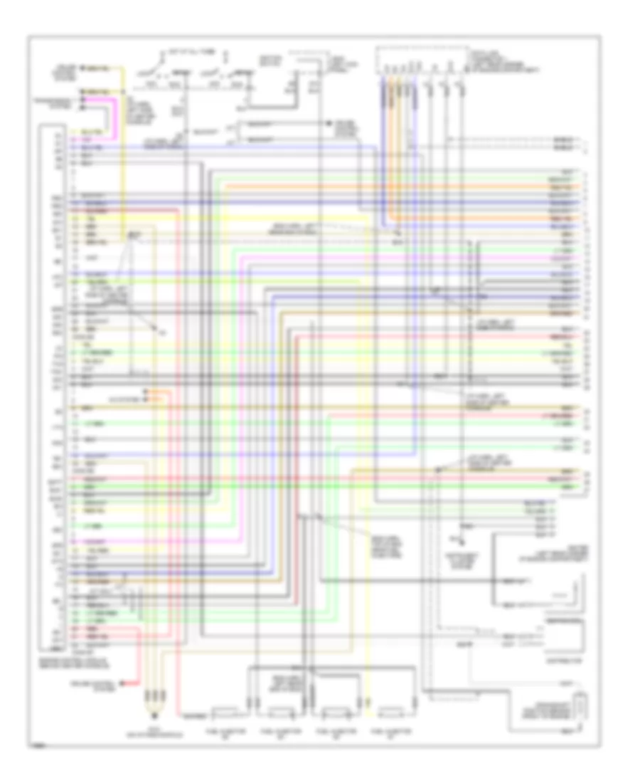
ENGINE PERFORMANCE
1.6L
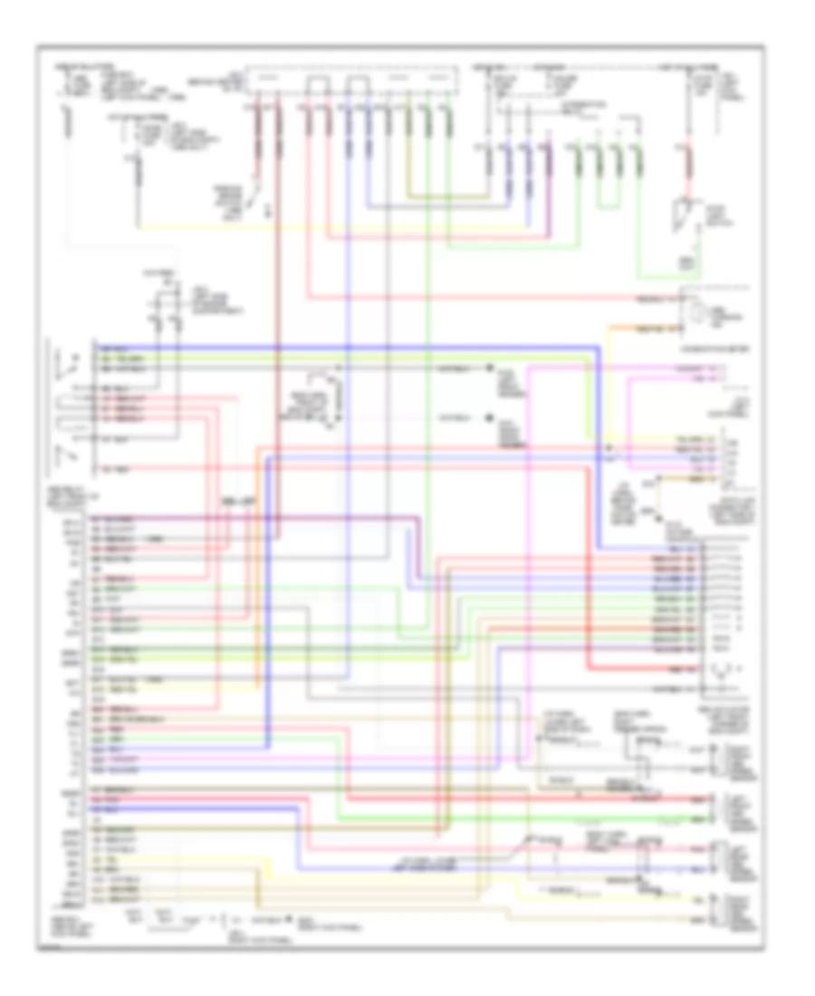
1.6L, Engine Performance Wiring Diagrams (1 of 3) for Toyota Corolla 1996
List of elements for 1.6L, Engine Performance Wiring Diagrams (1 of 3) for Toyota Corolla 1996:
- #10
- #20
- #30
- #40
- (eng harn, left rear end of eng)
- (eng harn, top of eng near fuel injectors)
- (i/p harn, left side of center console)
- (i/p harn, left side of radio)
- A/c system
- A/t
- A/t only
- Ac1
- Acc
- Act
- B/k
- Batt
- Conn e5
- Conn e6
- Conn e7
- Crankshaft position sensor (front of engine)
- Cruise control system
- Data link connector 1 (left rear corner of engine compartment)
- Distributor
- E01
- E02
- E03
- E13
- E16
- E18
- E21
- E36
- Egr
- Els1
- Els2
- Engine control module (behind center console)
- Fuel injector #1
- Fuel injector #2
- Fuel injector #3
- Fuel injector #4
- G13
- G131 (on intake manifold)
- Hot at all times
- Ht2
- I25 (i/p harn, left side of radio)
- I26
- I32 (i/p harn, left side of center console)
- I33
- I36
- Ig-
- Igf
- Igniter (left rear corner of engine compartment)
- Ignition coil
- Ignition switch
- Igt
- Instrument cluster system
- J/b #1 (left kick panel)
- Knk
- Lock
- M/t
- Ne-
- Nsw
- Od1
- Od2
- Ox1
- Ox2
- Pim
- Red
- Rsc
- Rso
- Run
- Sdl
- Shield
- Spd
- Sta
- Start
- Te1
- Tha
- Thw
- Transmission system
- Vta
1.6L, Engine Performance Wiring Diagrams (2 of 3) for Toyota Corolla 1996
List of elements for 1.6L, Engine Performance Wiring Diagrams (2 of 3) for Toyota Corolla 1996:
- (eng harn, left rear end of engine)
- (i/p harn, left side of center console)
- (i/p harn, left side of radio)
- (i/p harn, right side of comb meter)
- (i/p harn, right side of combination meter)
- A/t
- C12
- Circuit opening relay (behind front of center console)
- Clutch start switch (left side of i/p)
- Cruise control system
- Defog-i/up fuse 7.5a
- E17
- E18
- E18 (eng harn, left rear end of engine)
- Efi fuse 15a
- Efi relay
- G100 (front left fender)
- Heated oxygen sensor (below center console)
- Hot at all times
- Hot in run
- Hot w/ light switch on
- Hot w/ rear defogger on
- Ht2
- I18
- I26
- I34
- I44
- Ign fuse 10a
- Instrument cluster
- J/b #1 (left kick panel)
- J/b #2 (left side of engine compt)
- J3 junction connector (behind center of i/p)
- M/t
- Malfunction ind
- O/d off ind
- Ox2
- P/n
- Park/neutral switch (front of engine compt)
- Shield
- Speed input
- Starting/charging system
- Tail fuse 15a
- Throttle position sensor (right side of engine)
1.6L, Engine Performance Wiring Diagrams (3 of 3) for Toyota Corolla 1996
List of elements for 1.6L, Engine Performance Wiring Diagrams (3 of 3) for Toyota Corolla 1996:
- (eng harn, left rear end of engine) e17
- (i/p harn, left side of center console) i35
- A14
- A18
- Bat
- C10
- D11
- Data link connector 3 (below left side of i/p)
- Egr vsv (right side of engine)
- Engine coolant temp sensor (rear of engine)
- Fuel pump (below center rear of vehicle)
- Fuse block (left side of i/p)
- G131 (on intake manifold)
- G200 (left kick panel)
- G999 (left d pillar)
- Gauge fuse 10a
- Hot at all times
- Hot in run
- I49
- Idle air control valve (right side of engine)
- Intake air temp sensor (rear of engine)
- Integration relay
- J/b #1 (left kick panel)
- J/b #3 (behind center of i/p)
- J/b 1 (left kick panel)
- J/b 3 (behind i/p panel center)
- J3 junction connector (behind center of i/p)
- Knock sensor (top of engine)
- Manifold absolute pressure sensor (right rear of engine compartment)
- O/d switch (below center console)
- Obd fuse 7.5a
- Oxygen sensor (left side of engine)
- Park/neutral position switch (front of engine)
- Pim
- Red
- Sdl
- Shield
- Stop fuse 15a
- Stop light switch (below left side of i/p)
1.8L
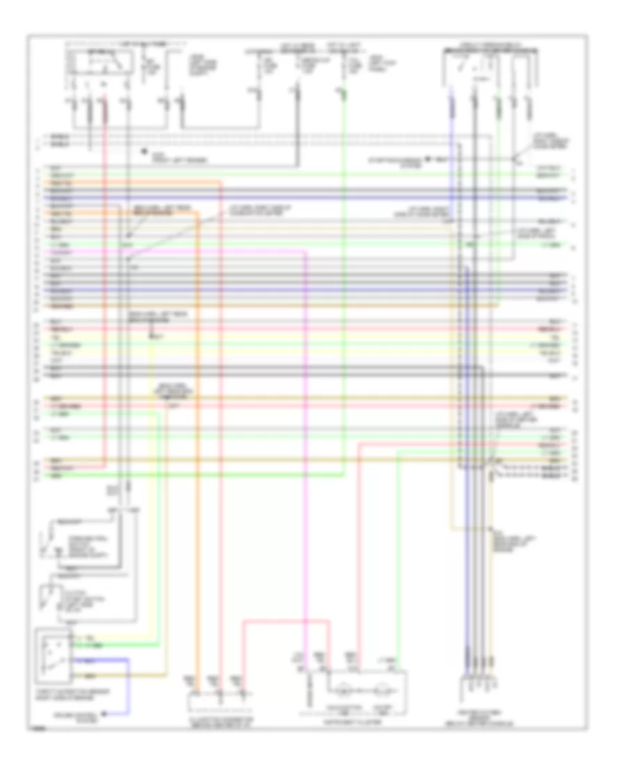
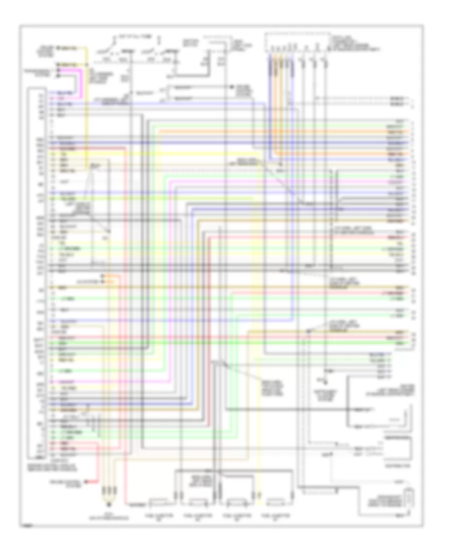
1.8L, Engine Performance Wiring Diagrams (1 of 3) for Toyota Corolla 1996
List of elements for 1.8L, Engine Performance Wiring Diagrams (1 of 3) for Toyota Corolla 1996:
- #10
- #20
- #30
- #40
- (eng harn, left rear end of eng)
- (eng harn, left rear eng)
- (eng harn, top of eng near fuel injectors)
- (i/p harn, left side of center console)
- (left side of center console)
- A/c system
- A/t
- A/t only
- Ac1
- Acc
- Act
- B/k
- Batt
- Conn e10
- Conn e8
- Conn e9
- Crankshaft position sensor (front of engine)
- Cruise control system
- Data link connector 1 (left rear corner of engine compartment)
- Distributor
- E01
- E02
- E03
- E13
- E16
- E18
- E21
- E36
- Egr
- Els1
- Els2
- Engine control module (behind center console)
- Fuel injector #1
- Fuel injector #2
- Fuel injector #3
- Fuel injector #4
- G13
- G131 (on intake manifold)
- Hot at all times
- Ht2
- I25 (i/p harness, left side of radio)
- I26 (i/p harness, left side of radio)
- I33
- I36
- Ig-
- Igf
- Igniter (left rear corner of engine compartment)
- Ignition coil
- Ignition switch
- Igt
- Instrument cluster system
- J/b #1 (left kick panel)
- Knk
- Lock
- M/t
- Ne-
- Nsw
- Od1
- Od2
- Ox1
- Ox2
- Pim
- Red
- Rsc
- Rso
- Run
- Sdl
- Shield
- Spd
- Sta
- Start
- Te1
- Tha
- Thw
- Transmission system
- Vta
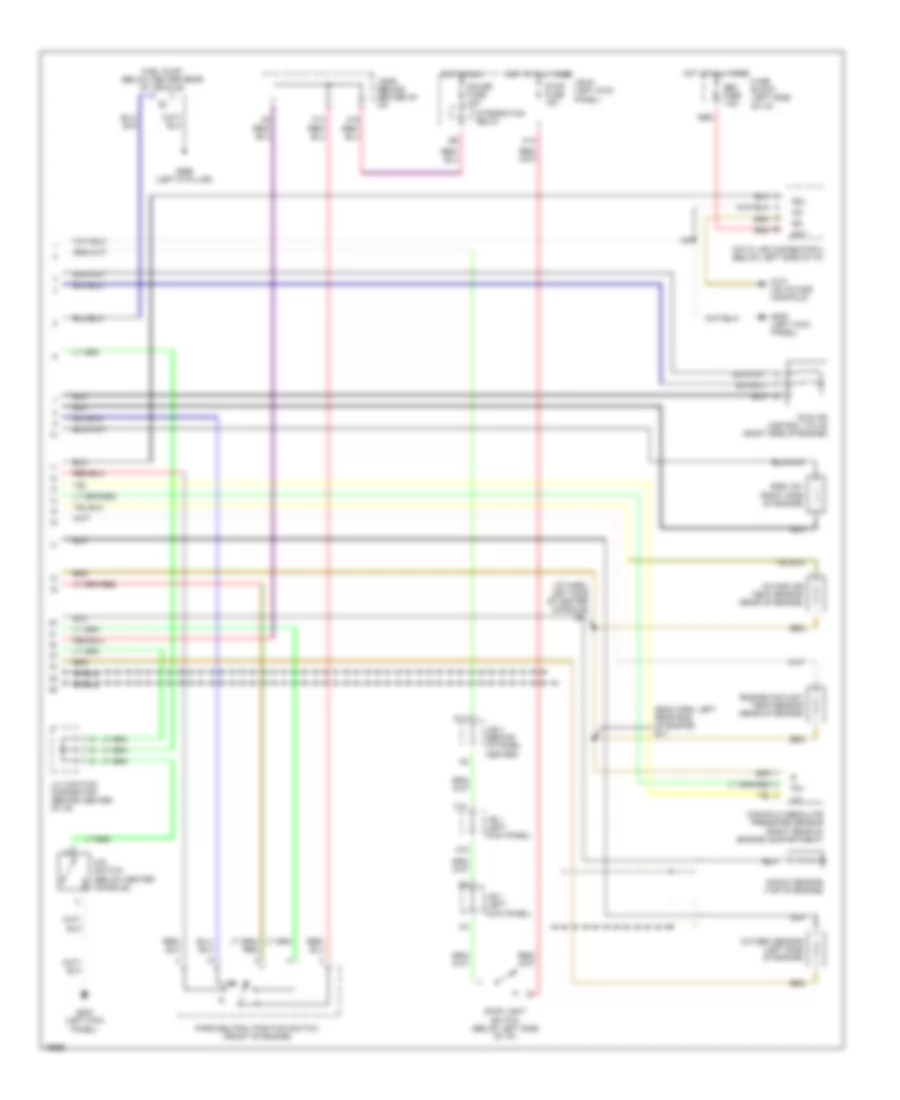
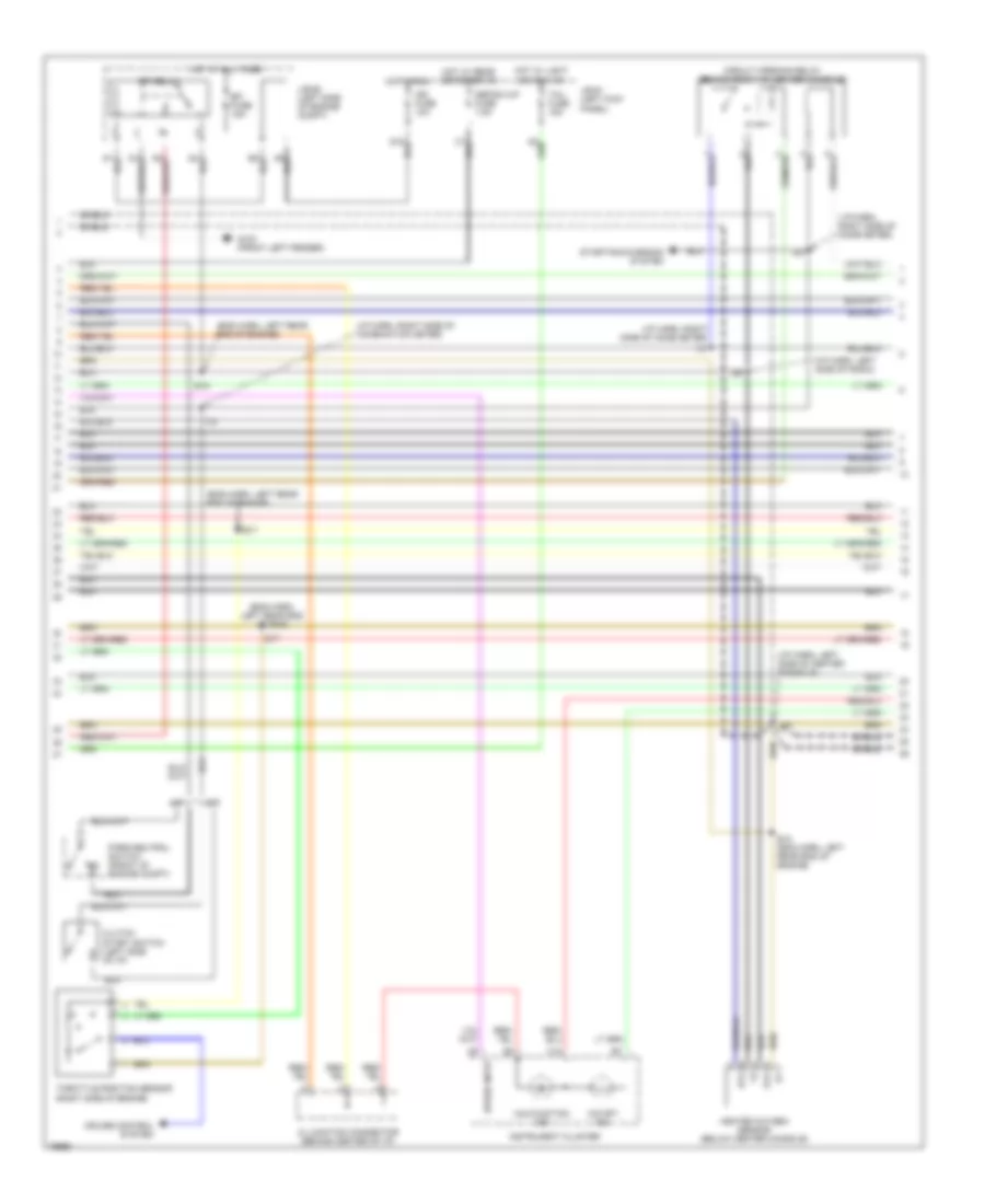
1.8L, Engine Performance Wiring Diagrams (2 of 3) for Toyota Corolla 1996
List of elements for 1.8L, Engine Performance Wiring Diagrams (2 of 3) for Toyota Corolla 1996:
- (eng harn, left rear end of eng)
- (eng harn, left rear end of engine)
- (i/p harn, left side of center console)
- (i/p harn, left side of radio)
- (i/p harn, right side of comb meter)
- (i/p harn, right side of combination meter)
- A/t
- C12
- Circuit opening relay (behind front of center console)
- Clutch start switch (left side of i/p)
- Cruise control system
- Defog-i/up fuse 7.5a
- E17
- E18
- E18 (eng harn, left rear end of engine)
- Efi fuse 15a
- Efi relay
- G100 (front left fender)
- Heated oxygen sensor (below center console)
- Hot at all times
- Hot in run
- Hot w/ light switch on
- Hot w/ rear defogger on
- Ht2
- I18
- I25
- I26
- I34
- Ign fuse 10a
- Instrument cluster
- J/b #1 (left kick panel)
- J/b #2 (left side of engine compt)
- J3 junction connector (behind center of i/p)
- M/t
- Malfunction ind
- O/d off ind
- Ox2
- P/n
- Park/neutral switch (front of engine compt)
- Shield
- Speed input
- Starting/charging system
- Tail fuse 15a
- Throttle position sensor (right side of engine)
1.8L, Engine Performance Wiring Diagrams (3 of 3) for Toyota Corolla 1996
List of elements for 1.8L, Engine Performance Wiring Diagrams (3 of 3) for Toyota Corolla 1996:
- (eng harn, left rear end of engine) e17
- A14
- A18
- Bat
- C10
- D11
- Data link connector 3 (below left side of i/p)
- Egr vsv (right side of engine)
- Engine coolant temp sensor (rear of engine)
- Fuel pump (below center rear of vehicle)
- Fuse block (left side of i/p)
- G131 (on intake manifold)
- G200 (left kick panel)
- G999 (left d pillar)
- Gauge fuse 10a
- Hot at all times
- Hot in run
- I35 (i/p harn, left side of center console)
- I49
- Idle air control valve (right side of engine)
- Intake air temp sensor (rear of engine)
- Integration relay
- J/b #1 (left kick panel)
- J/b #3 (behind center of i/p)
- J/b 1 (left kick panel)
- J/b 3 (behind i/p panel center)
- J3 junction connector (behind center of i/p)
- Knock sensor (top of engine)
- Manifold absolute pressure sensor (right rear of engine compartment)
- O/d switch (below center console)
- Obd fuse 7.5a
- Oxygen sensor (left side of engine)
- Park/neutral position switch (front of engine)
- Pim
- Red
- Sdl
- Shield
- Stop fuse 15a
- Stop light switch (below left side of i/p)
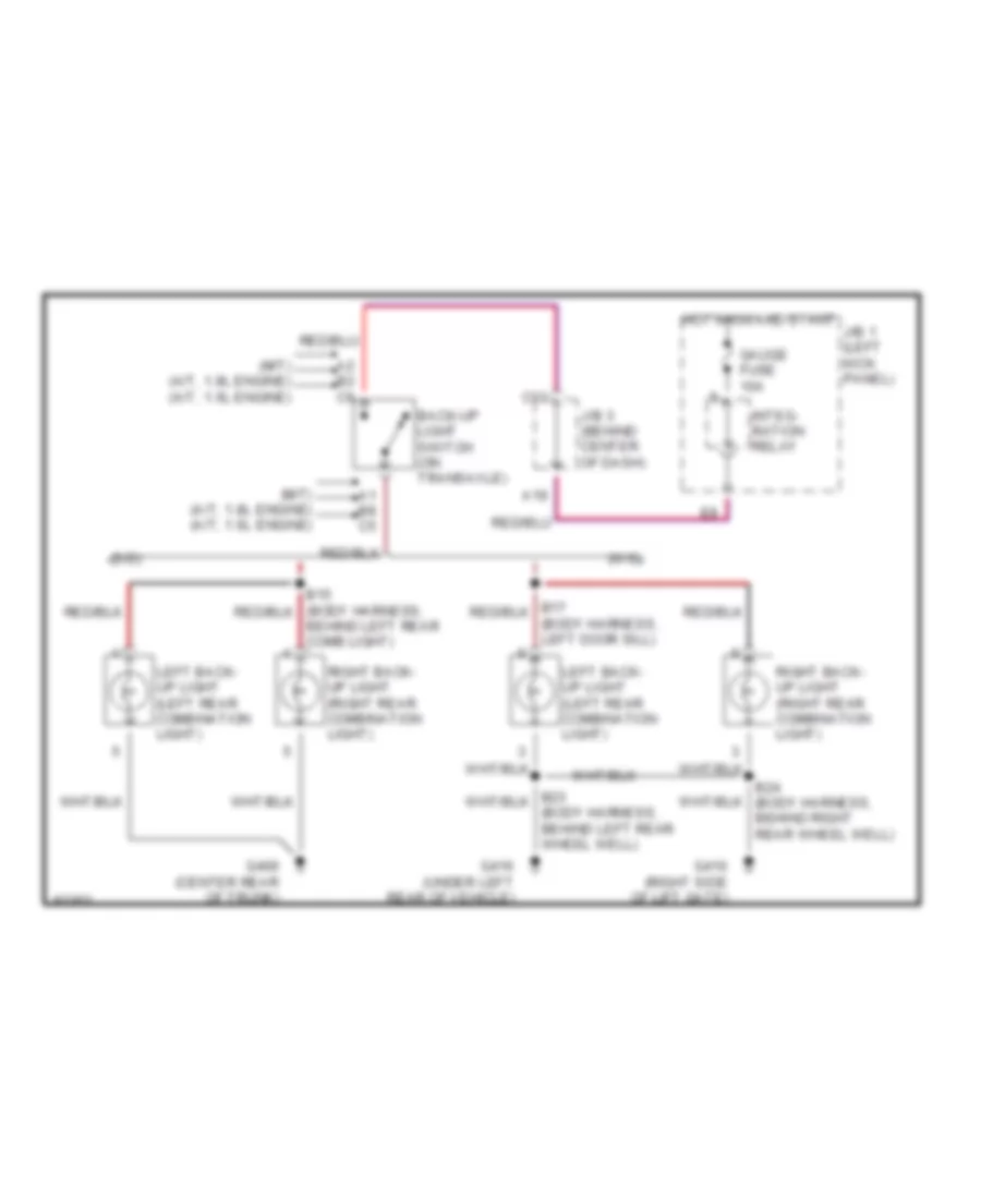
EXTERIOR LIGHTS
Back-up Lamps Wiring Diagram for Toyota Corolla 1996
List of elements for Back-up Lamps Wiring Diagram for Toyota Corolla 1996:
- (m/t) (a/t, 1.8l engine) (a/t, 1.6l engine)
- (s/d)
- (w/g)
- A1 b8 c5
- A19
- A2 b2 c6
- B24 (body harness, behind right rear wheel well)
- Back-up light switch (on transaxle)
- Behind left rear comb light)
- C13
- G406 (center rear of trunk)
- G410 (right side of lift gate)
- G416 (under left rear of vehicle)
- Gauge fuse 10a
- Hot in on and start
- Integ- ration relay
- J/b 1 (left kick panel)
- J/b 3 (behind center of dash)
- Left back- up light (left rear combination light)
- Right back- up light (right rear combination light)
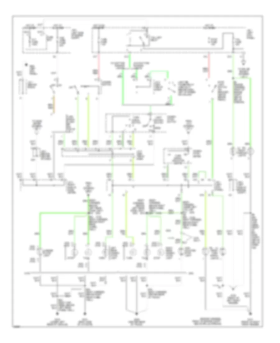
Exterior Lamps Wiring Diagram for Toyota Corolla 1996
List of elements for Exterior Lamps Wiring Diagram for Toyota Corolla 1996:
- (body harness, behind left rear comb light) b15
- (body harness, behind right rear wheel well) b24 or
- (engine harness, front of engine compt, above grille opening)
- (s/d)
- (s/d) (w/g)
- (w/ daytime running lights)
- (w/g only)
- (w/g)
- (w/o daytime running lights)
- A13
- A14
- A17
- A18
- Alt fuse 100a
- B24 (body harness, behind right rear wheel well)
- C19
- C20
- Combin- ation meter
- Combin- ation switch
- E6 (en- gine har- ness, front of en- gine compt, above grille open- ing)
- E8 (engine harness, front of engine compt, above grille opening)
- From j/b 1 (diagram 1 of 1)
- From j/c 3 (diagram 1 of 1)
- Fuse box
- G10
- G100 (front of left front fender)
- G101 (front of right front fender)
- G16
- G200 (left kick panel)
- G406 (center rear of trunk)
- G410 (right side of liftgate)
- G416 (under left rear of vehicle)
- Haz- horn fuse 20a
- Hazard switch
- Head
- High mounted stop light
- Hot at all times
- Hot in on or start
- J/b 1 (left kick panel)
- J/b 2 (left side of engine compt)
- J/b 3 (behind center of dash)
- J/c 1 (behind radio)
- J/c 2 (cen- ter of dash)
- J/c 3 (right side of comb meter)
- Left rear combin- ation light
- Left rear wheel well)
- Lh rh front parking lights
- License plate light
- Light control switch
- Light re- tainer relay (1995 only) (behind dash, left of steer- ing column)
- Off
- Rh lh front turn signal lights
- Right rear combin- ation light
- Stop
- Stop fuse 15a
- Stop light switch (on bracket, above brake pedal)
- Tail
- Tail fuse 15a
- Taillight relay
- To comb meter (diagram 1 of 1)
- To splice b24/b15 (diagram 1 of 1)
- Turn
- Turn fuse 7.5a
- Turn signal flash- er (on top of j/b 1)
- Turn signal indicator lights
- Turn signal switch
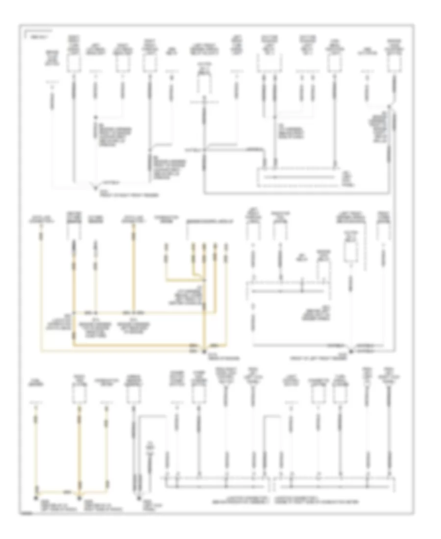
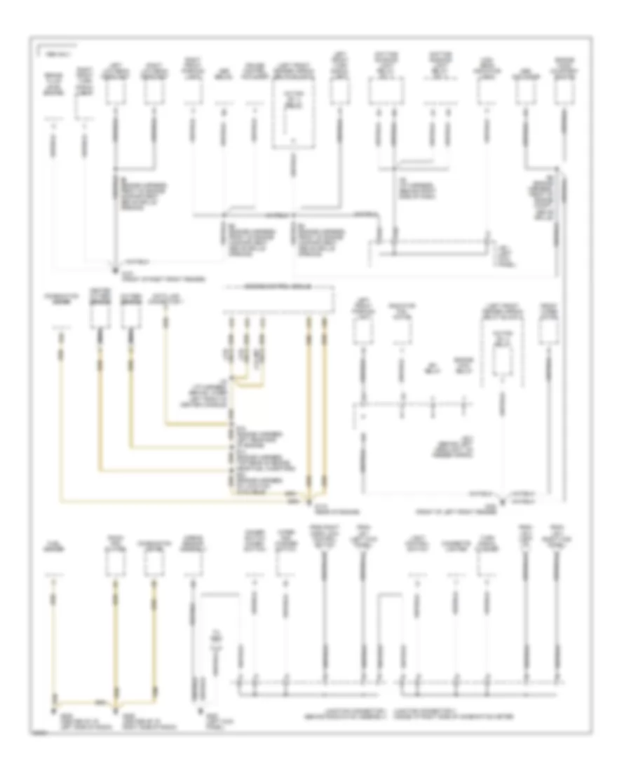
GROUND DISTRIBUTION
Ground Distribution Wiring Diagram (1 of 4) for Toyota Corolla 1996
List of elements for Ground Distribution Wiring Diagram (1 of 4) for Toyota Corolla 1996:
- (left front fender apron) relay block 5
- 1996 only
- A/c fan no. 2 relay
- A/c fan no. 3 relay
- A10
- A13
- A26
- Abs actuator
- Abs relay
- Airbag sensor assembly
- B10
- B16
- Brake fluid level switch
- Cigarette lighter
- Combination meter
- Data link connector 1
- Data link connector 3
- Daytime running light relay no. 3
- Daytime running light relay no. 4
- Dimmer switch (combo. switch)
- E14 (engine harness, top of engine, near fuel injectors)
- E18 (engine harness, left rear end of engine)
- E22 (location information unavailable)
- E4 (engine harness, front of engine compt, above grille)
- E6 (engine harness, front of engine compartment, above grille opening)
- Efi relay
- Engine control module
- Engine hood courtesy switch
- Engine main relay
- From j/b 1 (left kick panel)
- From j/b 3 (left i/p)
- From j/b 4 (right kick panel)
- From right door lock control switch
- Front wiper motor
- Fuel sender
- G100 (front of left front fender)
- G101 (front of right front fender)
- G115 (rear of engine)
- G12
- G200 (left kick panel)
- G206 (center of i/p, left side of radio)
- G206 (center of i/p, right side of radio)
- Heated oxygen sensor
- High beam indicator light
- I38 (i/p harness, (behind right side of dash)
- J/b 1 (left kick panel)
- J/b 2 (behind left headlight, on fender apron)
- Junction connector 1 (behind radio/hvac assembly)
- Junction connector 3 (inside i/p, right side of combination meter)
- Left front parking light
- Left front turn signal light
- Left low beam headlight
- Light control switch
- Nca
- Oxygen sensor
- Radiator fan motor
- Radio and player
- Right front parking light
- Right front turn signal light
- Right low beam headlight
- To g203
- Turn signal flasher
- Wiper and washer switch
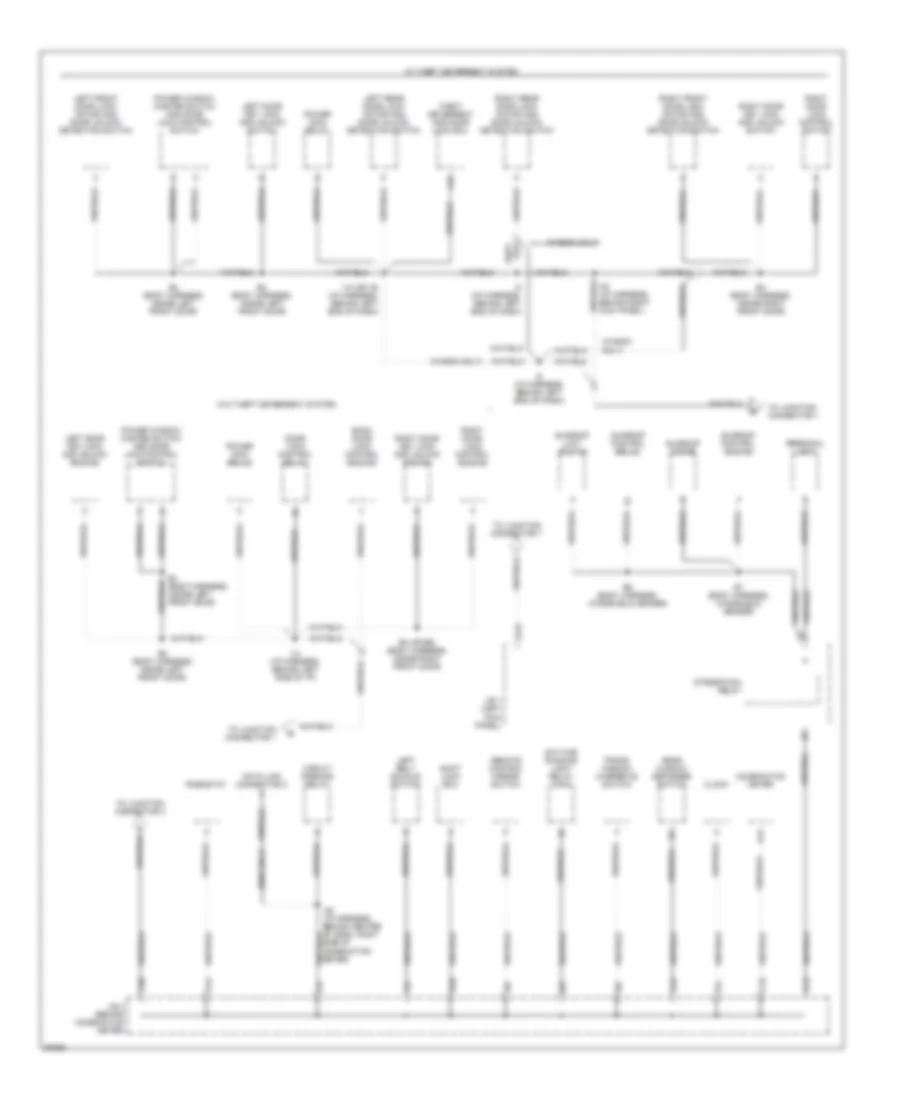
Ground Distribution Wiring Diagram (2 of 4) for Toyota Corolla 1996
List of elements for Ground Distribution Wiring Diagram (2 of 4) for Toyota Corolla 1996:
- (1.6l only)
- (left front fender apron) relay block 5
- 1995 only
- A/c fan no. 2 relay
- A/c fan no. 3 relay
- A10
- A13
- A14
- A15
- A24
- A26
- Abs actuator
- Abs relay
- Airbag sensor assembly
- B10
- Brake fluid level switch
- Cigarette lighter
- Combination meter
- Cruise control actuator
- Data link connector 1
- Daytime running light relay no. 3
- Daytime running light relay no. 4
- Dimmer switch (combo. switch)
- E14 (engine harness, top rear of engine near fuel injectors)
- E18 (engine harness, left rear end of engine)
- E22 (engine harness, no location available)
- E5 (engine harness, front of engine compartment, above grille opening)
- E6 (engine harness, front of engine compartment, above grille opening)
- E6 (engine harness, front of engine compt, above grille)
- Efi relay
- Engine control module
- Engine hood courtesy switch
- Engine main relay
- From j/b 1 (left kick panel)
- From j/b 3 (left i/p)
- From j/b 4 (right kick panel)
- From right door lock control switch
- Front wiper motor
- Fuel sender
- G100 (front of left front fender)
- G101 (front of right front fender)
- G115 (rear of engine)
- G12
- G200 (left kick panel)
- G206 (center of i/p, left side of radio)
- G206 (center of i/p, right side of radio)
- Heated oxygen sensor
- High beam indicator light
- I33 (i/p harness, behind lower left front of center console)
- I38 (i/p harness, (behind right side of dash)
- J/b 1 (left kick panel)
- J/b 2 (behind left headlight, on fender apron)
- Junction connector 1 (behind radio/hvac assembly)
- Junction connector 3 (inside i/p, right side of combination meter)
- Left front parking light
- Left front turn signal light
- Left low beam headlight
- Light control switch
- Nca
- Only) (1.6l m/t
- Only) (1.8l
- Oxygen sensor
- Radiator fan motor
- Radio and player
- Right front parking light
- Right front turn signal light
- Right low beam headlight
- To g203
- Turn signal flasher
- Wiper and washer switch
Ground Distribution Wiring Diagram (3 of 4) for Toyota Corolla 1996
List of elements for Ground Distribution Wiring Diagram (3 of 4) for Toyota Corolla 1996:
- (1996 only)
- (wagon only)
- A12
- A13
- A15
- A16
- B2 (body harness, inside left front door)
- B20
- B3 (body harness, inside left front door)
- B4 (body harness, inside right front door)
- B4 (or b5) (body harness, inside right front door)
- B6 (body harness, windshield header)
- B7 (body harness, windshield header)
- Back door lock control switch
- C19
- C20
- Circuit opening relay
- Clock
- Combination meter
- D12
- Data link connector 3
- Daytime running light relay (main)
- Door lock control relay
- I10 (or 19) (i/p harness, behind left end of dash)
- I13 (i/p harness, behind left side of i/p)
- I40 (i/p harness, behind right kick panel)
- I49 (i/p harness, behind center of dash, right side of combination meter)
- I5 (i/p harness, behind left end of dash)
- I8 (i/p harness, behind left end of dash)
- Integration relay
- J/b 1 (left kick panel)
- J/b 3 (behind combination meter)
- Left belt buckle switch
- Left door key lock and unlock switch
- Left front door lock motor and door unlock detection switch
- Left rear door lock motor and door unlock detection switch
- Personal light
- Power main relay
- Power window master switch and door lock control switch
- Rear window defogger switch
- Remote control mirror switch
- Rheostat
- Right door key lock and unlock switch
- Right door lock control switch
- Right front door lock motor and door unlock detection switch
- Right rear door lock motor and door unlock detection switch
- Shift lock ecu
- Sunroof control relay
- Sunroof control switch
- Sunroof limit switch
- Sunroof motor
- Theft deterrent and door lock ecu
- To junction connector 1
- To junction connector 3
- Trans- mission overdrive switch
- W/ theft deterrent system
- W/o theft deterrent system
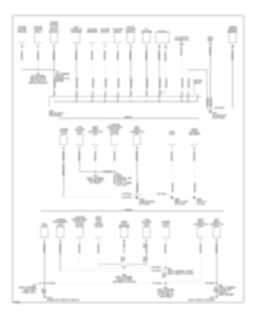
Ground Distribution Wiring Diagram (4 of 4) for Toyota Corolla 1996
List of elements for Ground Distribution Wiring Diagram (4 of 4) for Toyota Corolla 1996:
- (1996 only)
- A/c amplifier
- A10
- Abs ecu
- Airbag sensor assembly
- B14 (body harness, left front of trunk, under 'd' pillar)
- B16 (body harness, center rear of trunk)
- B18 (body harness, above left wheel well)
- B23 (body harness, lower left side of rear fender)
- B24 (body harness, under left 'd' pillar, behind trim panel)
- B26 (body harness, upper right side of liftgate)
- B28 (body harness, inside lower center of liftgate)
- Back door lock control motor
- Blower resistor
- Blower switch
- C10
- Cruise control clutch switch (m/t only)
- Cruise control ecu
- Cruise control switch
- From g200
- Fuel pump
- G203 (lower right kick panel)
- G406 (center rear of trunk)
- G410 (right side of liftgate)
- G416 (under left rear of vehicle)
- G998 (right 'd' pillar)
- G999 (below left 'd' pillar)
- Heater relay
- High mounted stop light
- I16 (i/p harness, behind combination meter)
- I25 (i/p harness, behind lower left front of center console)
- J/b 4 (behind right kick panel)
- Key interlock solenoid
- Left rear combination light
- License plate light
- Luggage compartment door key unlock switch
- Luggage compartment light switch
- Rear window defogger
- Right rear combination light
- Sedan
- Starter relay
- To junction connector 3
- Unlock warning switch
- Wagon
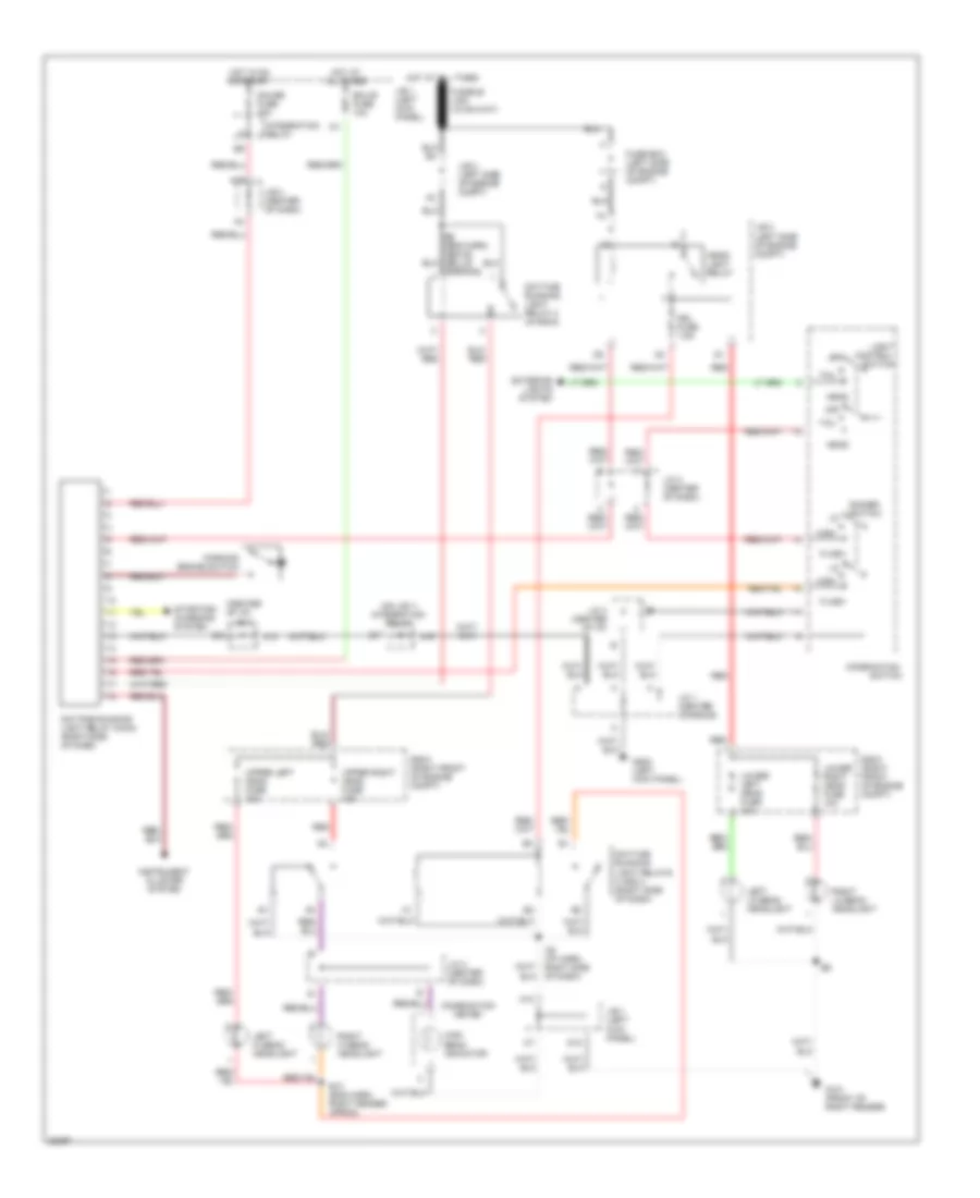
HEADLIGHTS
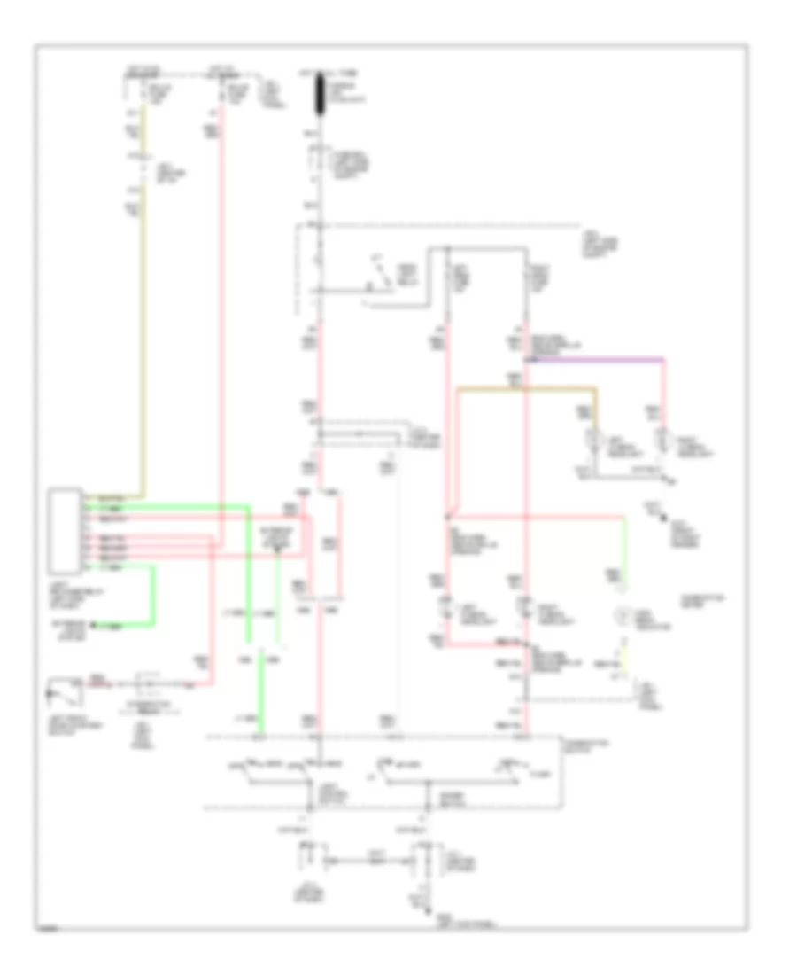
Headlight Wiring Diagram, with DRL for Toyota Corolla 1996
List of elements for Headlight Wiring Diagram, with DRL for Toyota Corolla 1996:
- (center of i/p)
- (on j/b 1) integration relay
- A10
- A13
- A15
- A19
- Combination
- Combination meter
- Control
- Daytime running light relay (main) (right side of dash)
- Daytime running light relay 2 (in r/b 6)
- Daytime running light relays 3 and 4 (right side of dash)
- Dimmer switch
- Drl fuse 7.5a
- E10 (eng harn, right fender apron)
- E8 (eng harn, above grille opening)
- Ecu-b fuse 10a
- Exterior lights system
- Flash
- Fuse box (left side of engine compt)
- G101 (front of right fender)
- G12
- G200 (left kick panel)
- Gauge fuse 10a
- Head
- Head- light relay
- High
- High beam indicator
- Hot at all times
- Hot in on or start
- I38 (i/p harn, right side of dash)
- Instrument cluster system
- Integration relay
- J/b 1 (left kick panel)
- J/b 2 (left side of engine compt)
- J/b 3
- J/b 3 (center of dash)
- J/c 1 (center console)
- J/c 2 (center of dash)
- J/c 3 (center of i/p)
- Left hi beam headlight
- Left lo beam headlight
- Light
- Lower left head fuse 10a
- Lower right head fuse 10a
- Off
- Parking brake switch
- R/b 6 (right front of engine compt)
- Red
- Right hi beam headlight
- Right lo beam headlight
- Starting/ charging system
- Switch
- Tail
- Upper left head fuse 10a
- Upper right head fuse 10a
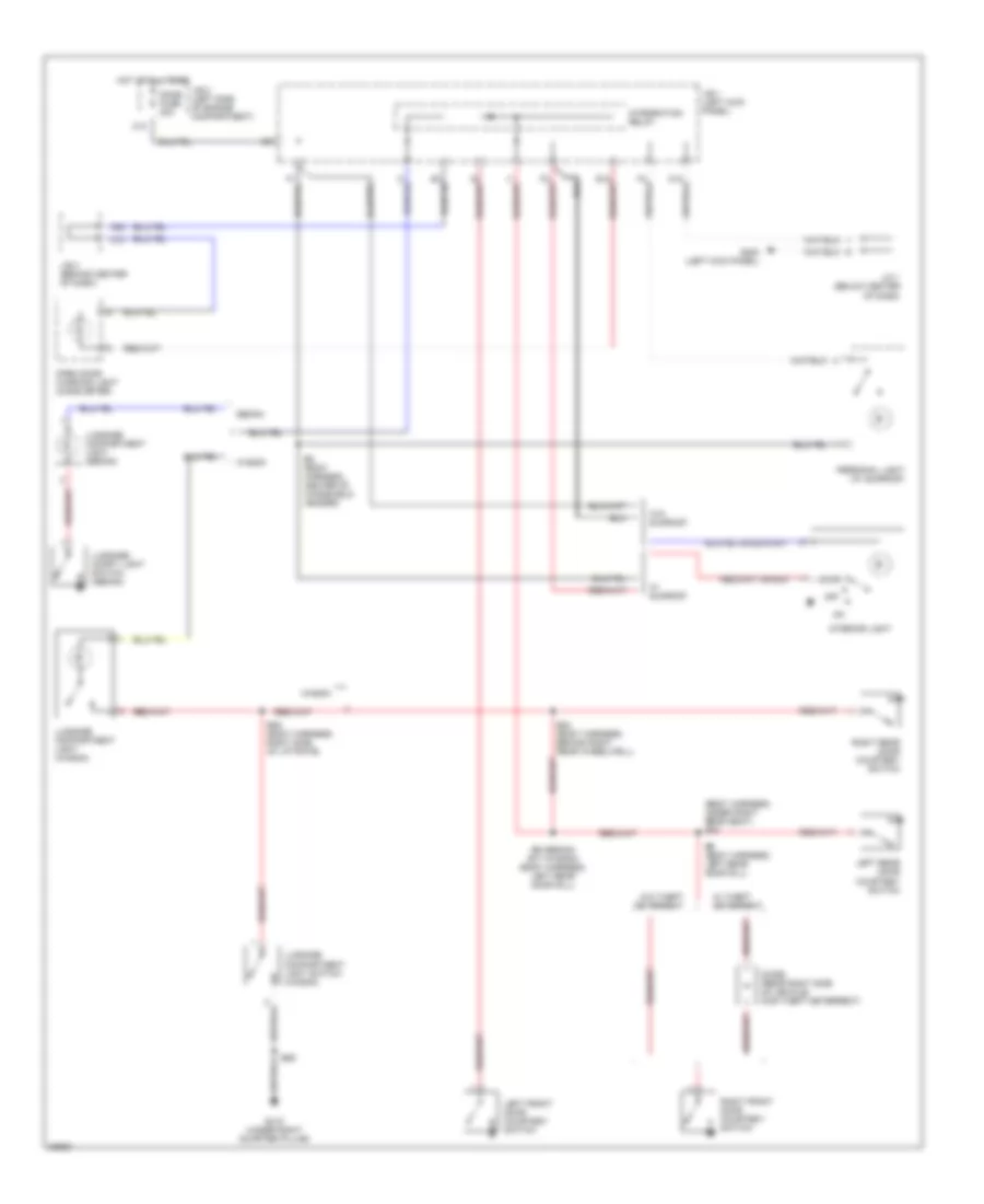
Headlight Wiring Diagram, without DRL for Toyota Corolla 1996
List of elements for Headlight Wiring Diagram, without DRL for Toyota Corolla 1996:
- A10
- A17
- A18
- Above grrille opening) e7
- Combination meter
- Combination switch
- D11
- Dimmer switch
- E2 (eng harn, above grille opening)
- E2 (eng harn, above grrille opening)
- Ecu-b fuse 10a
- Ecu-ig fuse 15a
- Exterior lights system
- Flash
- Fuse box (left side of engine compt)
- G101 (front of right fender)
- G12
- G200 (left kick panel)
- Head
- Head- light relay
- High
- High beam indicator
- Hot at all times
- Hot in on or start
- Integration relay
- J/b 1 (left kick panel)
- J/b 2 (left side of engine compt)
- J/b 3 (center of i/p)
- J/c 1 (center of dash)
- J/c 2 (center of dash)
- J/c 3 (center of dash)
- Left front door courtesy switch
- Left head fuse 15a
- Left hi beam headlight
- Left lo beam headlight
- Light control switch
- Light retainer relay (left side of dash)
- Off
- Right head fuse 15a
- Right hi beam headlight
- Right lo beam headlight
- Tail
HORN
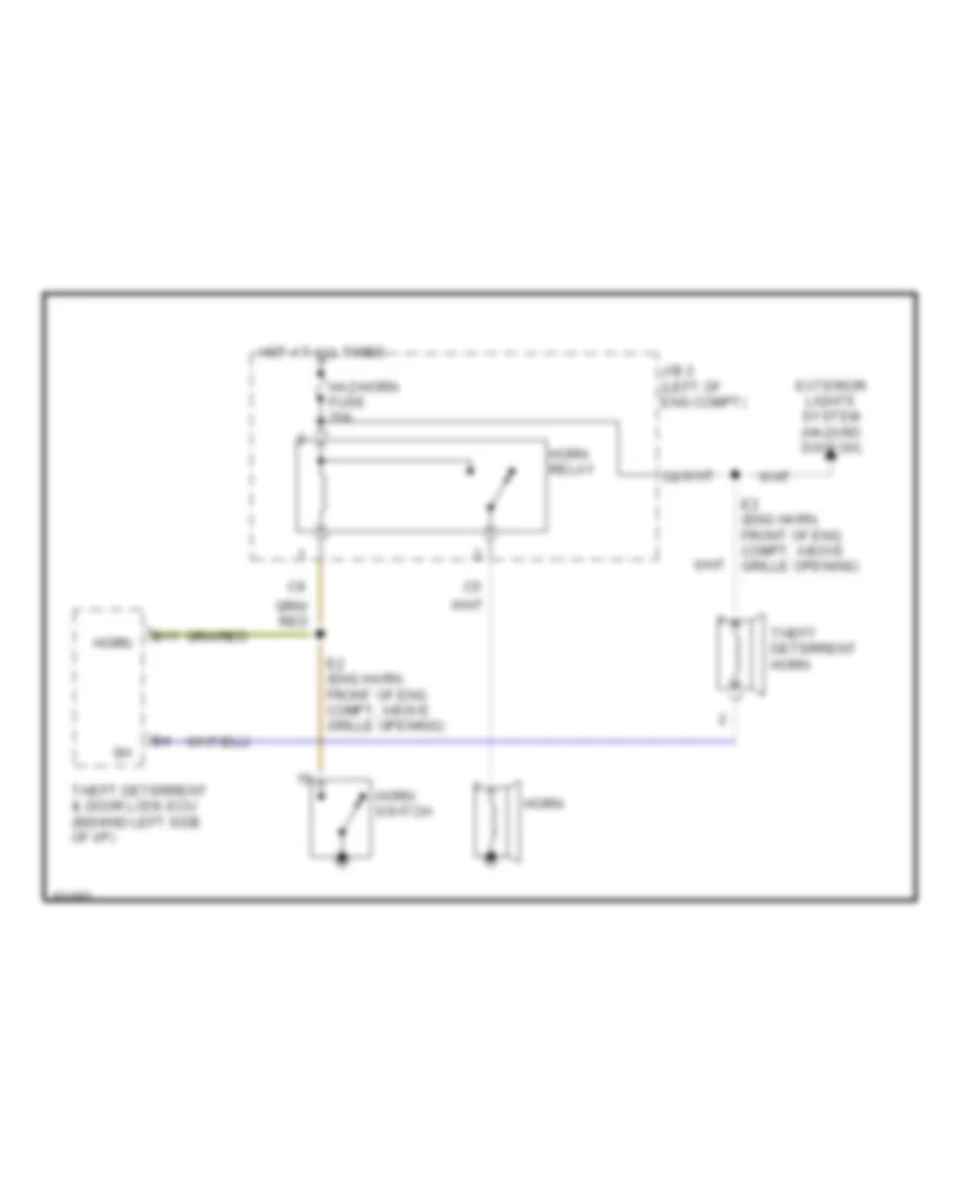
Horn Wiring Diagram for Toyota Corolla 1996
List of elements for Horn Wiring Diagram for Toyota Corolla 1996:
- B11
- E2 (eng harn, front of eng compt, above grille opening)
- Exterior lights system (hazard switch)
- Haz-horn fuse 20a
- Horn
- Horn relay
- Horn switch
- Hot at all times
- J/b 2 (left of eng compt)
- Theft deterrent & door lock ecu (behind left side of i/p)
- Theft deterrent horn
INSTRUMENT CLUSTER
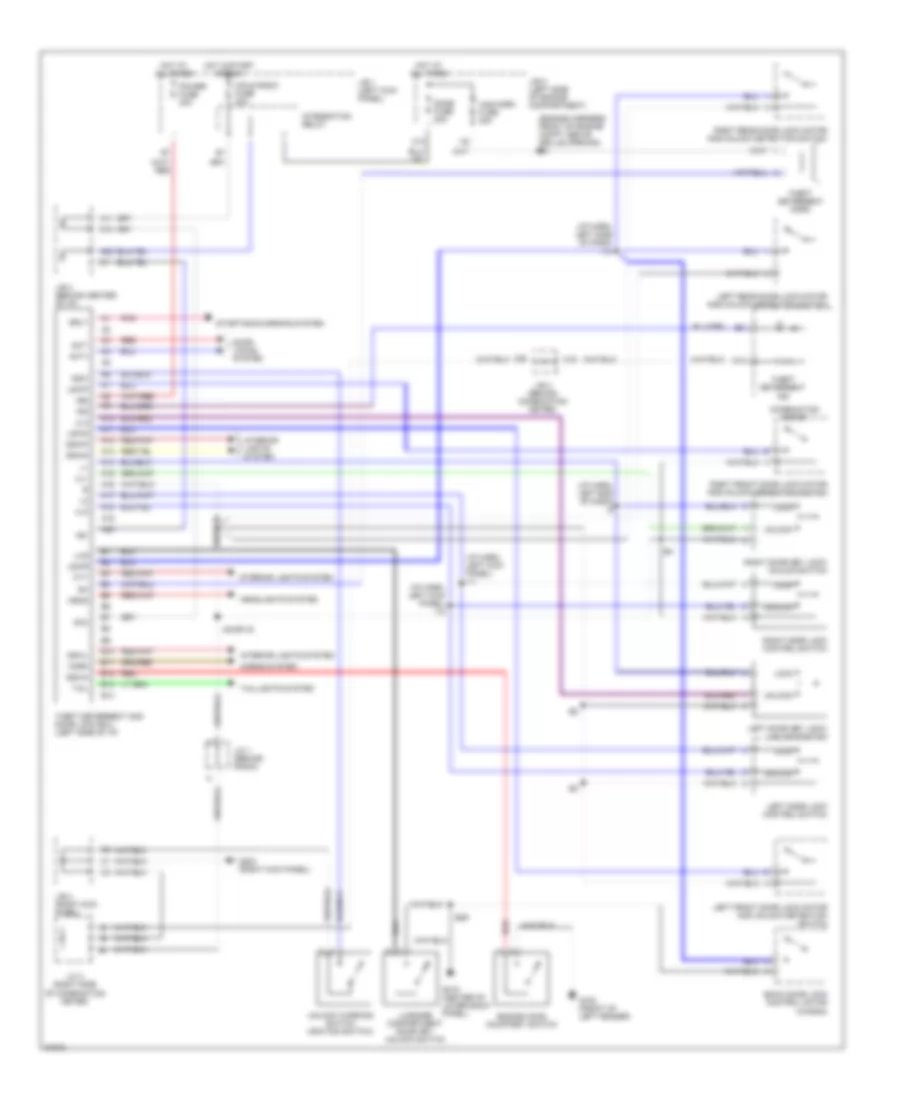
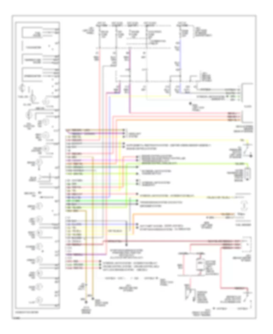
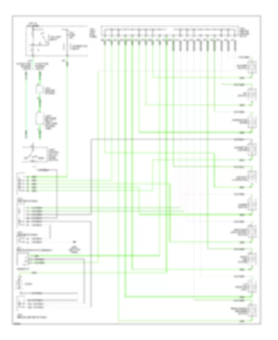
Instrument Cluster Wiring Diagram for Toyota Corolla 1996
List of elements for Instrument Cluster Wiring Diagram for Toyota Corolla 1996:
- (abs ecu)
- (alternator)
- (canada)
- (center airbag sensor assembly)
- (cruise control ecu)
- (door lock ecu)
- (integration relay)
- (usa)
- 0/d off ind
- A10
- A11
- A12
- A13
- A16
- A19
- A22
- Abs ind
- Airbag ind
- Anti-lock brakes system
- Anti-theft system
- B10
- Brake fluid level switch (fluid reservoir)
- Brake ind
- Brk
- Bulb check
- C10
- C11
- C12
- C13
- C14
- C15
- C16
- C17
- C19
- C20
- Charge ind
- Cig & radio fuse 20a
- Clock
- Combination meter
- Cruise control ind
- Cruise control system
- Daytime running light relay (above glove box)
- Defog ind
- Defogger system
- Dome fuse 20a
- Door ind
- Ecu-b fuse 10a
- Engine controls system
- Engine controls system (engine and electronic controlled transmission ecu) (a/t) (engine control module) (m/t)
- Exterior lights system (hazard switch)
- Fuel gauge
- Fuel ind
- Fuel sender
- G101 (front of right front fender)
- G115 (rear of engine)
- G200 (left kick panel)
- G203 (right kick panel)
- G206 (left side of radio)
- G206 (right side of radio)
- Gauge fuse 10a
- Headlight system
- High beam ind
- Hot at all times
- Hot in acc and on
- Hot in on & start
- I33 (1996 only)
- Ign fuse 10a
- Illum
- Integration relay
- Interior lights system
- Interior lights system (rheostat)
- J/b 1 (left kick panel)
- J/b 2 (left side of engine compartment)
- J/b 3 (behind center of dash)
- Left turn ind
- Mal- function ind
- Oil ind
- Oil pressure switch (left side of engine)
- Parking brake switch (center console)
- Pkb
- Red
- Right turn ind
- Seat belt ind
- Security ind
- Speedometer
- Starting/charging system
- Starting/charging system (park/neutral position switch) (a/t) (clutch start switch) (m/t)
- Tachometer
- Temperature gauge
- Transmissions system (o/d switch)
- Vehicle speed sensor (rear of engine)
- W/ drl
- W/o drl
- Water temperature sender (top of engine)
INTERIOR LIGHTS
Courtesy Lamps Wiring Diagram for Toyota Corolla 1996
List of elements for Courtesy Lamps Wiring Diagram for Toyota Corolla 1996:
- (body harness, under right rear seat) b19
- A22
- B24 (body harness, behind right rear wheelwell)
- B26
- B29 (body harness, right side of liftgate)
- B8 (body harness, center of windshield header)
- B9 (body harness, left rear door sill)
- B9 (sedan) b17 (wagon) (body harness, left rear door sill)
- C10
- Diode (rear right side of vehicle) (for theft deterrent)
- Dome fuse 20a
- Door
- G200 (left kick panel)
- G415 (under right quarter pillar)
- Hot at all times
- Integration relay
- Interior light
- J/b 1 (left kick panel)
- J/b 2 (left side of engine compartment)
- J/b 3 (behind center of dash)
- J/c 1 (below center of dash)
- Left front door courtesy switch
- Left rear door courtesy switch
- Luggage compartment light (sedan)
- Luggage compartment light (wagon)
- Luggage compartment light switch (wagon)
- Luggage compt light switch (sedan)
- Off
- Open door warning light (comb meter)
- Personal light (w/ sunroof)
- Right front door courtesy switch
- Right rear door courtesy switch
- Sedan
- W/ sunroof
- W/ theft deterrent
- W/o sunroof
- W/o theft deterrent
- Wagon
Instrument Illumination Wiring Diagram for Toyota Corolla 1996
List of elements for Instrument Illumination Wiring Diagram for Toyota Corolla 1996:
- A/c switch
- A/t indicator light
- A13
- Ashtray illumination
- Back door lock control switch
- Blower switch
- C20
- Cigarette lighter
- Clock
- Combination meter
- D12
- G200 (left kick panel)
- Hazard switch
- Head
- Hot at all times
- Ill-
- Integration relay
- J/b 1 (left kick panel)
- J/b 3 (behind center of dash)
- J/b 3 (behind center of i/p)
- J/c 1 (behind radio/hvac assembly)
- J/c 2 (center of dash)
- J/c 3 (center of dash)
- Light control switch (comb switch)
- Light retainer relay (left side of dash) (1995)
- Off
- Radio and player
- Rear window defogger switch
- Rheostat
- Tail
- Tail fuse 15a
- Taillight relay
- W/ daytime running lights
- W/o daytime running lights
POWER DISTRIBUTION
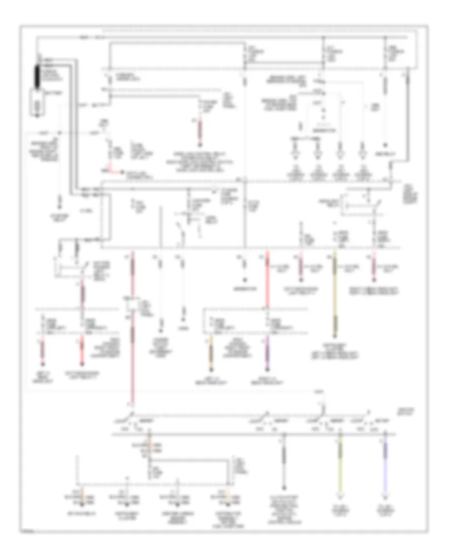
Power Distribution Wiring Diagram (1 of 3) for Toyota Corolla 1996
List of elements for Power Distribution Wiring Diagram (1 of 3) for Toyota Corolla 1996:
- (center) airbag sensor assembly
- (engine harn, left rear end of engine) e19
- 15a
- Abs fusible link 50a
- Abs relay
- Acc
- Alt fusible link 100a
- Alt-s fuse 7.5a
- Am1 fusible link 40a
- Am2
- Battery
- Clutch start switch (m/t), park/neutral position switch (a/t), engine control module
- D1 red
- Data link connector 3
- Daytime running light relay 2 (r/b 6)
- Daytime running light relay 3
- Daytime running light relay 4
- Distributor assembly, igniter, fuel injectors
- Door lock control relay, power main relay, back door lock control switch, theft deterrent & door lock control ecu
- Drl fuse 7.5a
- E15 (engine harn, top of engine near fuel injectors)
- E8 (engine harn, front of engine compt, above grille opening)
- Efi main relay
- Fuse 20a
- Fuse 30a
- Fuse block (left side of j/b 1)
- Fuse box (inside j/b 2)
- G13
- G14
- G15
- Generator
- Haz-horn
- Hazard switch, theft deterrent horn
- Head fuse (left)
- Head fuse (lwr-left) 10a
- Head fuse (lwr-right) 10a
- Head fuse (right)
- Head fuse (upr-left) 10a
- Head fuse (upr-right) 10a
- Headlight relay
- Horn
- Horn relay
- Ign fuse 10a
- Ignition switch
- Instrument cluster
- Instrument cluster, left hi beam headlight, left lo beam headlight
- J/b 1 (left kick panel)
- J/b 2 (left side of engine compt)
- Left hi beam headlight
- Left lo beam headlight
- Lock
- Obd fuse 7.5a
- Only
- Power fuse 30a
- R/b 6 (canada) (right front of engine compartment)
- Red
- Right hi beam headlight, right lo beam headlight
- Right lo beam headlight
- Start
- Starter relay
- To dome fuse (diagram 2 of 3)
- To j/b 1 (diagram 2 of 3)
- To j/b 1 (diagram 3 of 3)
- To j/b 2 (diagram 2 of 3)
- To j/b 4 (diagram 2 of 3)
- W/ drl
- W/ drl only
- W/o drl only
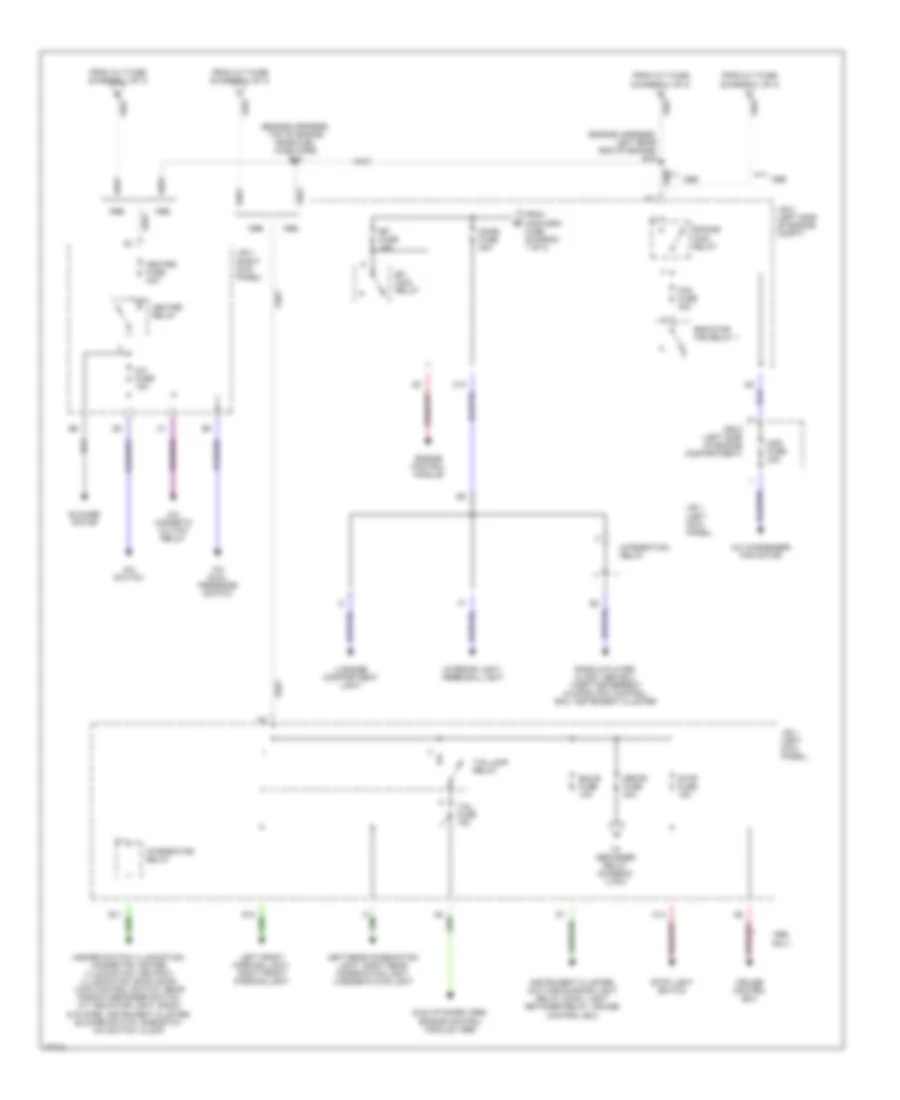
Power Distribution Wiring Diagram (2 of 3) for Toyota Corolla 1996
List of elements for Power Distribution Wiring Diagram (2 of 3) for Toyota Corolla 1996:
- (diagram 1 of 3)
- (engine harness, left rear end of engine) e19
- (engine harness, top of engine near fuel injectors) e15
- A/c condenser fan motor
- A/c dual pressure switch
- A/c fuse 15a
- A/c magnetic clutch relay
- A/c switch
- A14
- Blower motor
- C10
- Cds fuse 30a
- Cruise control ecu
- Defog fuse 30a
- Dome fuse 20a
- Ecu-b fuse 10a
- Efi fuse 15a
- Efi main relay
- Engine control module
- Engine main relay
- Fan fuse 30a
- From alt fuse
- From alt fuse (diagram 1 of 3)
- From haz-horn fuse (diagram 1 of 3)
- Hazard switch illumination, cigarette lighter illumination, ashtray illumination, back door lock control switch, rear window defogger switch, a/t indicator light, radio & player, instrument cluster, blower switch, rheostat, a/c switch, clock
- Heater fuse 40a
- Heater relay
- Idle up diode (1995), engine control module (1996)
- Instrument cluster, daytime running light relay (main), light retainer relay, cruise control ecu
- Integration relay
- Interior light, personal light
- J/b 1 (left kick panel)
- J/b 2 (left side of engine compt)
- J/b 4 (right kick panel)
- Left front parking light, right front parking light
- Left rear combination light, right rear combination light, license plate light
- Luggage compartment light
- Only
- R/b 5 (left side of engine compartment)
- Radiator fan relay 1
- Radio & player, clock, abs ecu, theft deterrent & door lock control ecu, instrument cluster
- Stop fuse 15a
- Stop light switch
- Tail fuse 15a
- Taillamp relay
- To defogger relay (diagram 3 of3)
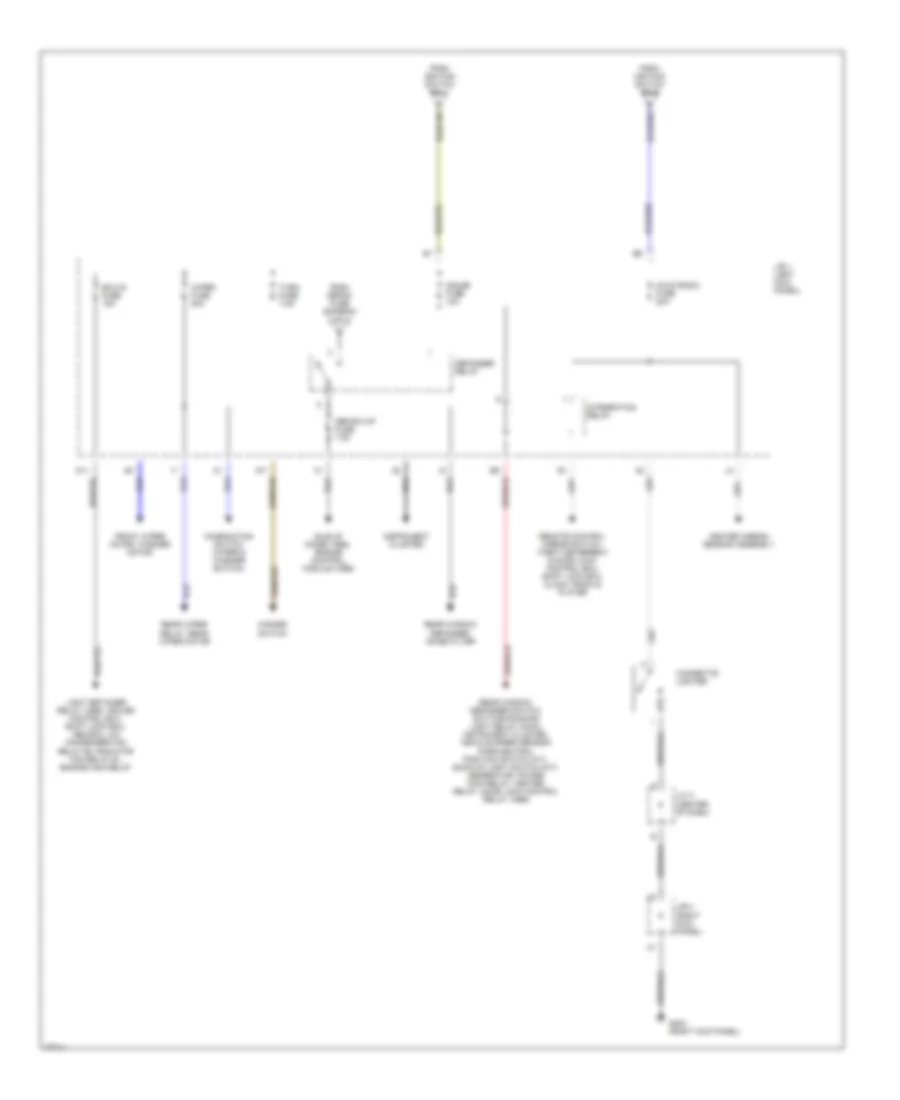
Power Distribution Wiring Diagram (3 of 3) for Toyota Corolla 1996
List of elements for Power Distribution Wiring Diagram (3 of 3) for Toyota Corolla 1996:
- (center of dash)
- (right kick panel)
- A17
- Center airbag sensor assembly
- Cig & radio fuse 20a
- Cigarette lighter
- Combination switch (wiper & washer switch)
- D11
- Defog-i/up fuse 7.5a
- Defogger relay
- Ecu-ig fuse 15a
- From defog fuse (diagram 2 of 3)
- From ignition switch pin 4
- From ignition switch pin 5
- Front wiper motor, washer motor
- G203 (right kick panel)
- Gauge fuse 10a
- Hazard switch
- Idle-up diode (1995), engine control module (1996)
- Instrument cluster
- Integration relay
- J/b 1 (left kick panel)
- J/b 4
- J/c 3
- Light retainer relay (1995), cruise control ecu, shift lock ecu, abs ecu, a/c condenser fan relay #2, radiator fan relay #1, engine main relay
- Rear window defogger switch, daytime running light relay (main), instrument cluster, vehicle speed sensor, park/neutral position switch (a/t), back-up light switch (m/t), generator, power main relay, heater relay, door lock control relay (1996)
- Rear window defogger, noise filter
- Rear wiper relay, rear wiper motor
- Remote control mirror switch, theft deterrent & door lock control ecu, shift lock ecu, clock, radio & player
- Turn fuse 7.5a
- Wiper fuse 20a
POWER DOOR LOCKS
Power Door Lock Wiring Diagram, Sedan with Anti-theft for Toyota Corolla 1996
List of elements for Power Door Lock Wiring Diagram, Sedan with Anti-theft for Toyota Corolla 1996:
- (i/p harn,
- (i/p harn, left kick panel) i10
- (i/p harn, left kick panel) i11
- (i/p harn, left kick pnl) i9
- (i/p harn, top center of dash) i28
- (i/p harness, left kick panel) i6
- (i/p harness, left kick panel) i7
- (i/p harness, left kick panel) i8
- (i/p harness, right kick panel)
- +b1
- +b2
- A10
- A11
- A12
- A13
- A14
- A15
- A16
- A17
- A18
- A19
- A20
- A22
- Acc
- Act+
- Act-
- All times
- Anti-theft system
- B10
- B11
- B12
- B13
- B14
- B2 (body harn, inside left front door)
- B3 (body harn, inside left front door)
- B4 (body harn, left kick panel)
- B4 (body harn, left kick pnl)
- C10
- Cig & radio fuse 20a
- Cty
- D10
- Dome fuse 30a
- Dswd
- Dswh
- Dswl
- Dswp
- Engine hood courtesy switch
- Exterior lights system
- G100 (front left fender)
- G203 (right kick panel)
- G415 (center of lower back panel)
- Head
- Headlights system
- Horn
- Horns system
- Hot at
- Hot at all times
- Hot in start
- I10 left kick panel)
- I13 (i/p harn, left side of dash)
- I40
- I7 (i/p harness, left kick panel)
- I9 (i/p harn, left kick pnl)
- Ind
- Integration relay
- Interior lights system
- J/b 1 (left kick panel)
- J/b 2 (left side of engine compartment)
- J/b 3 (behind center of i/p)
- J/b 4 (right kick panel)
- Junction connector j1 (center of i/p)
- Junction connector j3 (center of i/p)
- Ksw
- Left door key lock/ unlock switch
- Left door lock control switch
- Left front door lock and unlock detection switch
- Left rear door lock and unlock detection switch
- Lock
- Lswd
- Lswp
- Lswr
- Lug
- Luggage compartment door key unlock switch
- Or run
- Pnk
- Power fuse 30a
- Red
- Right door key lock/ unlock switch
- Right door lock control switch
- Right front door lock and unlock detection switch
- Right rear door lock and unlock detection switch
- Srly
- Starting/charging system
- Tail
- Theft deterrent and door lock ecu (left side of i/p)
- Ul1
- Ul2
- Ul3
- Unlock
- Unlock warning switch (ignition switch)
Power Door Lock Wiring Diagram, Sedan without Anti-theft for Toyota Corolla 1996
List of elements for Power Door Lock Wiring Diagram, Sedan without Anti-theft for Toyota Corolla 1996:
- (body harn, inside left front door)
- (body harness, left "c" pillar) b4 b5
- (i/p harn, left kick panel) i6
- (i/p harn, left kick panel) i7
- (i/p harn, left kick panel) red i8
- (i/p harn, top center of dash) i27
- (i/p harness, top center of dash) i27
- (w/ power window) (w/o power window)
- A19
- B14
- B2 b3 (body harn, inside left front door)
- Door lock control relay (right side of dash)
- G200 (left kick panel)
- Gauge fuse 10a
- Hot at all times
- Hot in on or start
- I13 (i/p harness, left side of dash)
- I27 (i/p harn, top center of dash)
- I6 (i/p harn, left kick panel)
- Integration relay
- J/b 1 (left kick panel)
- J/b 3 (behind center of dash)
- Junction connector j1 (below center of i/p)
- Left door key lock/
- Left door lock control switch
- Left front door courtesy switch
- Left front door lock motor
- Left rear door lock motor
- Lock
- Lock timer
- Power fuse 30a
- Red
- Right door key lock/ unlock switch
- Right door lock control switch
- Right front door lock motor
- Right rear door lock motor
- Solid state
- Unlock
- Unlock switch
- Unlock timer
Power Door Lock Wiring Diagram, Wagon with Anti-theft for Toyota Corolla 1996
List of elements for Power Door Lock Wiring Diagram, Wagon with Anti-theft for Toyota Corolla 1996:
- (i/p harn, (left kick panel) i9
- (i/p harn, left kick panel) i11
- (i/p harn, left kick panel) i12
- (i/p harn, left kick panel) i4
- (i/p harness,
- (i/p harness, left kick panel)
- +b1
- +b2
- A10
- A11
- A12
- A13
- A14
- A15
- A16
- A17
- A18
- A19
- A20
- A22
- Acc
- Act+
- Act-
- Anti-theft system
- B10
- B11
- B12
- B13
- B14
- B2 (body harn, inside left front door)
- B24
- B28 (body harness, top center of dash)
- B3 (body harn, inside left front door)
- B4 (body harness, left 'c' pillar)
- Back door lock motor (wagon)
- C10
- Cig & radio fuse 20a
- Cty
- D10
- Dome fuse 30a
- Dswd
- Dswh
- Dswp
- Engine hood courtesy switch
- Exterior lights system
- G100 (front left fender)
- G203 (right kick panel)
- G998 (under right quarter pillar)
- Head
- Headlights system
- Horn
- Horns system
- Hot at all times
- Hot in start or run
- I10 (i/p harn, left kick panel)
- I12 left kick panel)
- I13 (i/p harn, left side of dash)
- I4 (i/p harness, left kick panel)
- I5 (i/p harn, left kick panel)
- Ind
- Integ- ration relay
- Interior lights system
- J/b 1 (left kick panel)
- J/b 2 (left side of engine compartment)
- J/b 3 (behind center of dash)
- J/b 3 (behind center of i/p)
- J/b 4 (right kick panel)
- Junction connector 1 (center of dash)
- Junction connector 3 (center of dash)
- Ksw
- Left door key lock/ unlock switch
- Left door lock control switch
- Left front door lock and unlock detection switch
- Left rear door lock and unlock detection switch
- Lock
- Lswd
- Lswp
- Lswr
- Lug
- Luggage compartment door key unlock switch
- Pnk
- Power fuse 30a
- Red
- Right door key lock/ unlock switch
- Right door lock control switch
- Right front door lock and unlock detection switch
- Right rear door lock and unlock detection switch
- Srly
- Starting/charging system
- Tail
- Theft deterrent and door lock ecu (left side of dash)
- Ul1
- Ul2
- Ul3
- Unlock
- Unlock warning switch (ignition switch)
Power Door Lock Wiring Diagram, Wagon without Anti-theft for Toyota Corolla 1996
List of elements for Power Door Lock Wiring Diagram, Wagon without Anti-theft for Toyota Corolla 1996:
- (i/p harn, top center of dash)
- (i/p harn, top center of dash) i27
- (i/p harness, top center of dash) i27
- (i/p harness, top center of dash) i31
- A19
- B14
- B2 (body harness, inside left front door)
- B4 (body harness, left "c" pillar)
- Back door lock control switch
- Back door lock motor (wagon)
- Door lock control relay (right side of dash)
- G200 (left kick panel)
- Hot at all times
- Hot in on or start
- I13 (i/p harn, left side of dash)
- I27
- I27 (i/p harn, top center of dash)
- I31 (i/p harn, top center of dash)
- Integ- ration relay
- Integration relay
- J/b 1 (left kick panel)
- J/b 3 (behind center of i/p)
- Junction connector j1 (below center of dash)
- Left door key lock/
- Left door lock control switch
- Left front door courtesy switch
- Left front door lock motor
- Left rear door lock motor
- Lock
- Lock timer
- Power fuse 30a
- Power window
- Red
- Right door key lock/ unlock switch
- Right door lock control switch
- Right front door lock motor
- Right rear door lock motor
- Solid state
- Unlock
- Unlock switch
- Unlock timer
- Wagon w/
- Wagon w/o power window
POWER MIRRORS
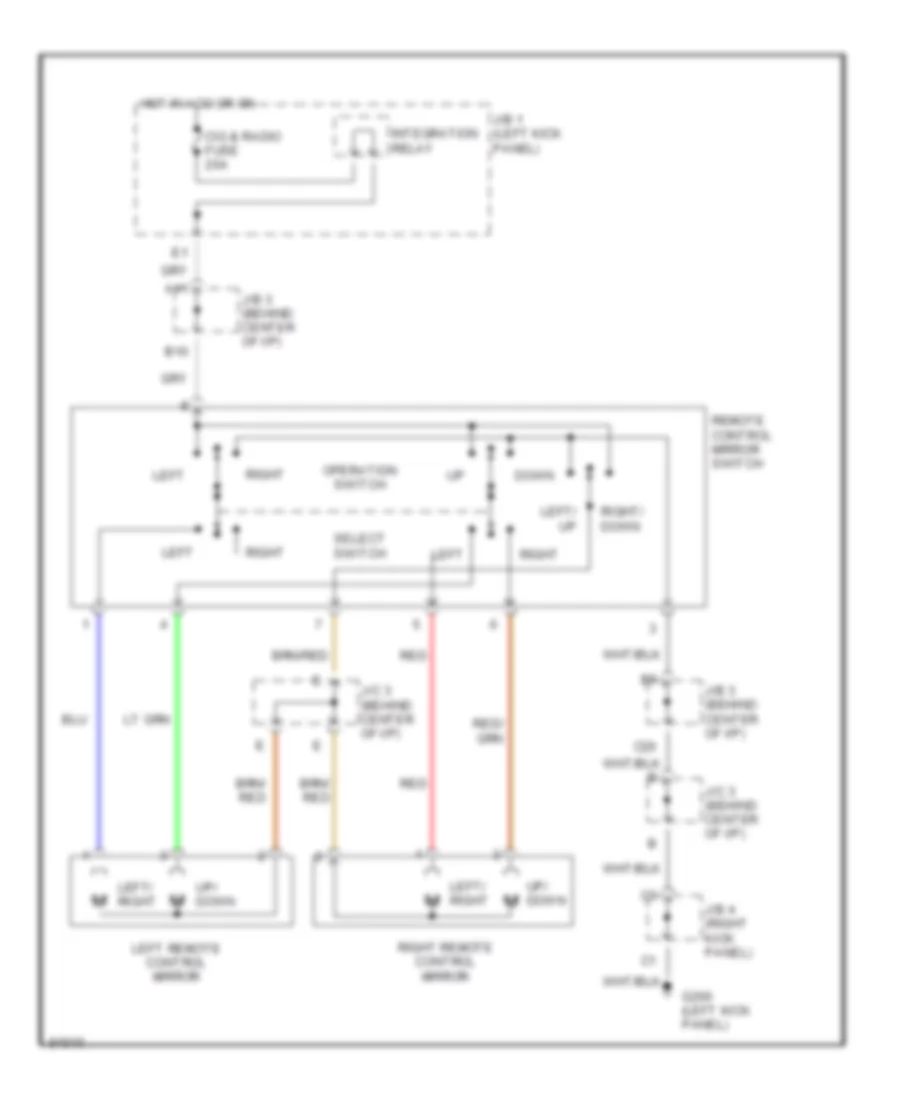
Power Mirror Wiring Diagram for Toyota Corolla 1996
List of elements for Power Mirror Wiring Diagram for Toyota Corolla 1996:
- A11
- B10
- C20
- Cig & radio fuse 20a
- Down
- G200 (left kick panel)
- Hot in acc or on
- Integration relay
- J/b 1 (left kick panel)
- J/b 3 (behind center of i/p)
- J/b 3 (behind center of i/p)
- J/b 4 (right kick panel)
- J/c 3 (behind center of i/p)
- J/c 3 (behind center of i/p)
- Left
- Left remote control mirror
- Left/ right
- Left/ up
- Operation switch
- Red
- Remote control mirror switch
- Right
- Right remote control mirror
- Right/ down
- Select switch
- Up/ down
POWER TOP/SUNROOF
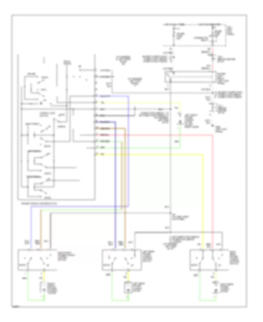
Power Top/Sunroof Wiring Diagrams for Toyota Corolla 1996
List of elements for Power Top/Sunroof Wiring Diagrams for Toyota Corolla 1996:
- A15
- A19
- B14
- Close
- D12
- Down
- G200 (left kick panel)
- Gauge fuse 10a
- Hot at all times
- Hot in on or start
- I9 i10 i13
- Integration relay
- J/b 1 (left kick panel)
- J/b 3 (behind center of dash)
- J/c 1 (behind center of dash)
- No.
- Open
- Pnk
- Power fuse 30a
- Power main relay (left kick panel)
- Red
- Solid state
- Sun roof control relay (front end of roof)
- Sun roof control switch
- Sun roof limit switch (front end of roof)
- Sun roof motor (front end of roof)
- Wagon w/ theft deterrent system sedan w/ theft deterrent system w/o theft deterrent system
POWER WINDOWS
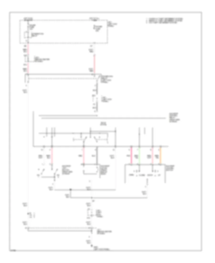
Power Window Wiring Diagram for Toyota Corolla 1996
List of elements for Power Window Wiring Diagram for Toyota Corolla 1996:
- (ex puerto rico sedan)
- (except puerto rico) (puerto rico sedan) (puerto rico wagon)
- (i/p harness, in left front door) b3
- (i/p harness, left kick panel) i1
- (puerto rico sedan)
- A19
- B14
- Down
- Driver
- G200 (left kick panel)
- Gauge fuse 10a
- Hot at all times
- Hot in on or start
- I13 (i/p harness. left side of i/p)
- I13 i10 i9
- I13 i8 (i/p harness, left side of i/p)
- I4 (ex puerto rico sedan) (puero rico sedan) (wagon)
- I40 (i/p harn, right kick panel)
- Integration relay
- J/b 1 (left kick panel)
- J/b 3 (behind center of i/p)
- J/c 1 (behind center of i/p)
- Left front power window motor (in left front door)
- Left rear
- Left rear power window control switch
- Left rear power window motor
- Lock
- Normal
- Power fuse 30a
- Power main relay (left kick panel)
- Power window master switch
- Right front
- Right front power window control switch
- Right front power window motor
- Right rear
- Right rear power window control switch
- Right rear power window motor
- Solid state
- Window lock switch
RADIO
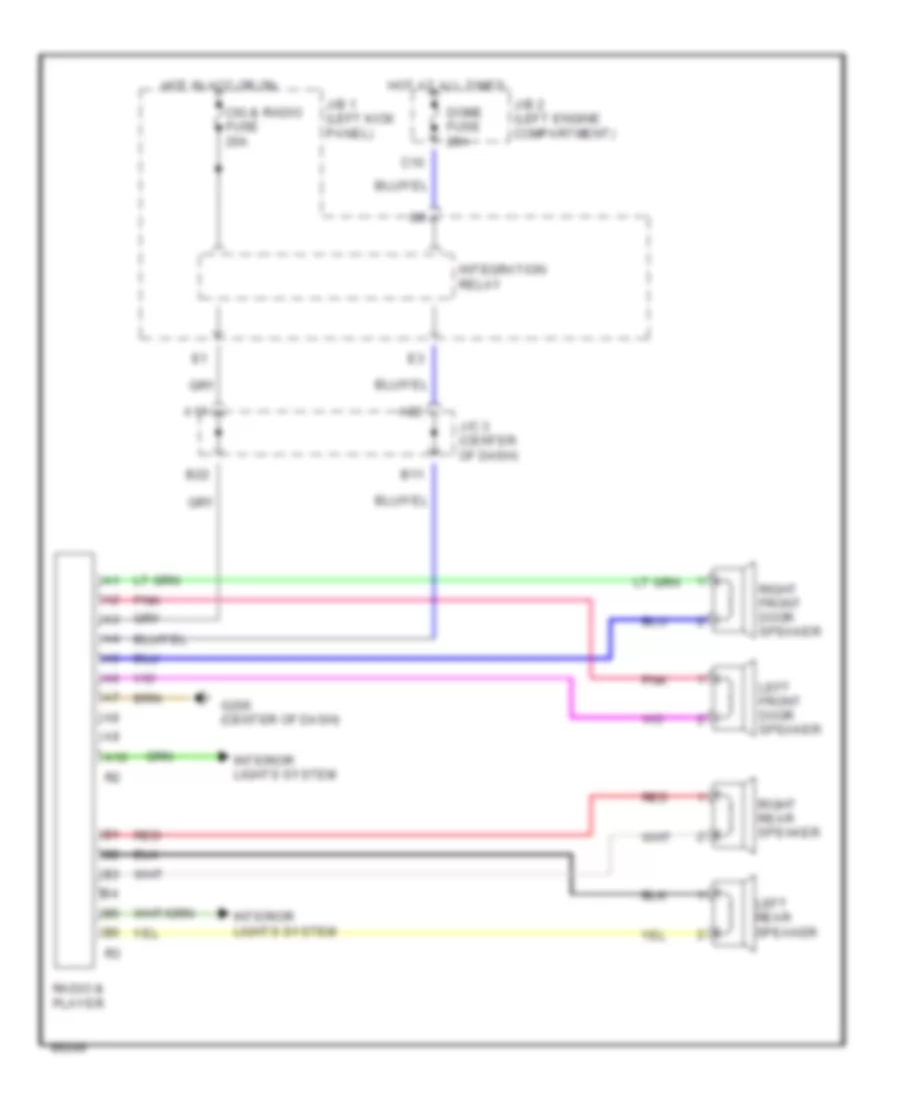
Radio Wiring Diagrams for Toyota Corolla 1996
List of elements for Radio Wiring Diagrams for Toyota Corolla 1996:
- A10
- A11
- A22
- B11
- B22
- C10
- Cig & radio fuse 20a
- Dome fuse 20a
- G206 (center of dash)
- Hot at all times
- Hot in acc or on
- Integration relay
- Interior lights system
- J/b 1 (left kick panel)
- J/b 2 (left engine compartment)
- J/c 3 (center of dash)
- Left front door speaker
- Left rear speaker
- Pnk
- Radio & player
- Red
- Right front door speaker
- Right rear speaker
SHIFT INTERLOCKS
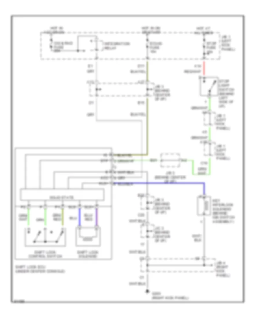
Shift Interlock Wiring Diagram for Toyota Corolla 1996
List of elements for Shift Interlock Wiring Diagram for Toyota Corolla 1996:
- A11
- A14
- A17
- A18
- Acc
- B15
- B20
- B21
- C10
- C20
- Cig & rad fuse 20a
- D11
- Ecu-ig fuse 15a
- G203 (right kick panel)
- Hot at all times
- Hot in acc or on
- Hot in on or start
- Integration relay
- J/b 1 (left kick panel)
- J/b 3 (behind center of i/p)
- J/b 3 (behind center of i/p)
- J/b 4 (right kick panel)
- J/c 3 (behind center of i/p)
- Key interlock solenoid (behind ign switch assembly)
- Kls+
- Shift lock control switch
- Shift lock ecu (under center console)
- Shift lock solenoid
- Sls+
- Sls-
- Solid state
- Stop fuse 15a
- Stop light switch (behind left side of i/p)
- Stp
STARTING/CHARGING
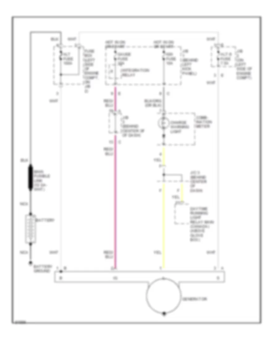
Charging Wiring Diagram for Toyota Corolla 1996
List of elements for Charging Wiring Diagram for Toyota Corolla 1996:
- Alt fuse 100a
- Alt-s fuse 7.5a
- Battery
- Battery ground
- Charge warning light
- Comb- ination meter
- Daytime running light relay main (canada) (above glove box)
- Fuse box (left side of engine compt, on j/b 2)
- Gauge fuse 10a
- Generator
- Hot in on or start
- Ign fuse 10a
- Integration relay
- J/b (behind center of of dash)
- J/b (behind left kick panel)
- J/b (on left side of engine compt)
- J/c 3 (behind center of dash)
- Nca
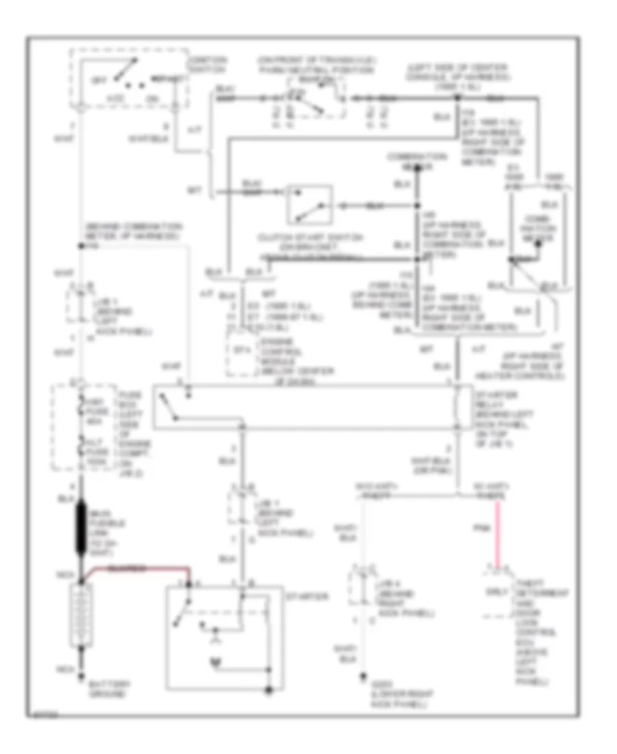
Starting Wiring Diagram for Toyota Corolla 1996
List of elements for Starting Wiring Diagram for Toyota Corolla 1996:
- (1.6l)
- (1.8l)
- (1995 1.6l) (1996-97 1.6l) (1.8l)
- (behind combination meter, i/p harness) i14
- (i/p harness, behind comb meter)
- (left side of center console, i/p harness) (1995 1.6l) i33
- (on front of transaxle) park/ neutral position switch
- 1.6l
- A/t
- Acc
- Alt fuse 100a
- Am1 fuse 40a
- Battery ground
- Clutch start switch (on bracket, above clutch pedal)
- Comb- ination meter
- Combination meter
- E5 e7 e10
- Engine control module (below center
- Ex 1.6l
- Fuse box (left side of engine compt, on j/b 2)
- G203 (lower right kick panel)
- I16 (1995 1.6l) i44 (ex 1995 1.6l) (i/p harness, right side of combination meter)
- I18 (ex 1995 1.6l) (i/p harness, right side of combination meter)
- I45 (i/p harness, right side of combination meter)
- I47 (i/p harness, right side of heater controls)
- Ignition switch
- J/b 1 (behind left kick panel)
- J/b 4 (behind right kick panel)
- M/t
- Nca
- Of dash)
- Off
- P/n
- Pnk
- Srly
- Sta
- Start
- Starter
- Starter relay (behind left kick panel, on top of j/b 1)
- Theft deterrent and door lock control ecu (above left kick panel)
- W/ anti- theft
- W/o anti- theft
SUPPLEMENTAL RESTRAINTS
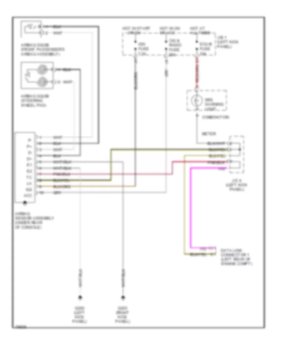
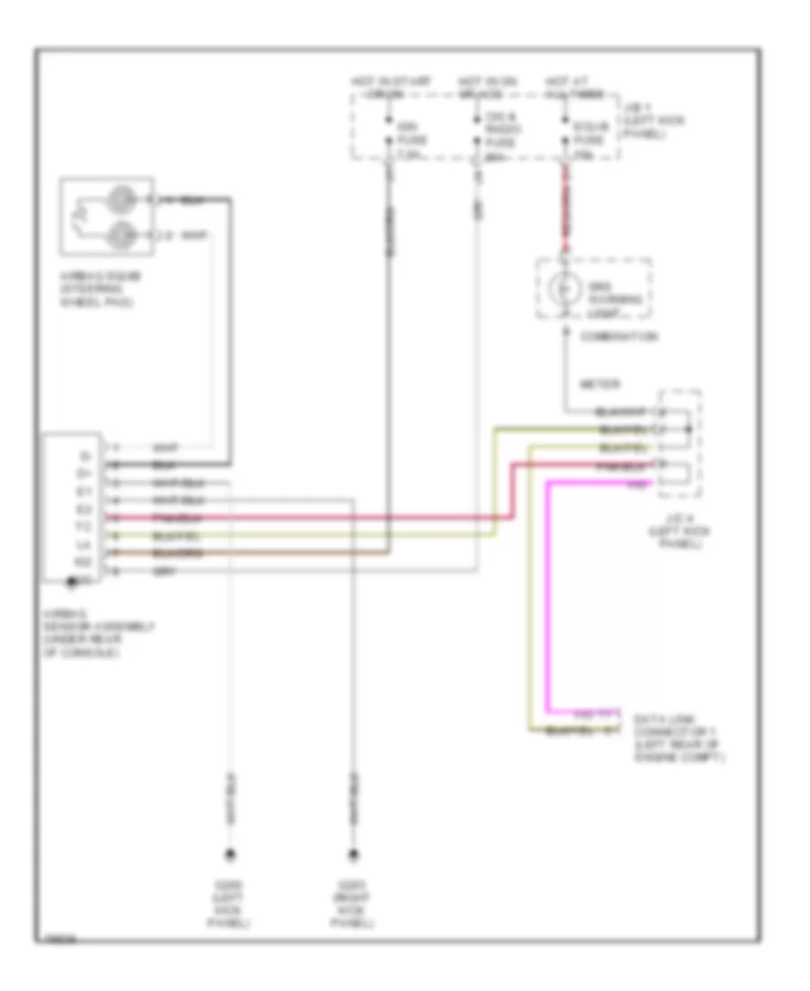
Supplemental Restraint Wiring Diagram, with Front Passenger Airbag Assembly for Toyota Corolla 1996
List of elements for Supplemental Restraint Wiring Diagram, with Front Passenger Airbag Assembly for Toyota Corolla 1996:
- Acc
- Airbag sensor assembly (under rear of console)
- Airbag squib (front passenger's airbag assembly)
- Airbag squib (steering wheel pad)
- Cig & radio fuse 20a
- Combination
- Data link connector 1 (left rear of engine compt)
- Ecu-b fuse 10a
- G200 (left kick panel)
- G203 (right kick panel)
- Hot at all times
- Hot in on or acc
- Hot in start
- Ig2
- Ign fuse 7.5a
- J/b 1 (left kick panel)
- J/c 4 (left kick panel)
- Meter
- Or on
- Srs warning light
Supplemental Restraint Wiring Diagram, without Front Passenger Airbag Assembly for Toyota Corolla 1996
List of elements for Supplemental Restraint Wiring Diagram, without Front Passenger Airbag Assembly for Toyota Corolla 1996:
- Acc
- Airbag sensor assembly (under rear of console)
- Airbag squib (steering wheel pad)
- Cig & radio fuse 20a
- Combination
- Data link connector 1 (left rear of engine compt)
- Ecu-b fuse 10a
- G200 (left kick panel)
- G203 (right kick panel)
- Hot at all times
- Hot in on or acc
- Hot in start
- Ig2
- Ign fuse 7.5a
- J/b 1 (left kick panel)
- J/c 4 (left kick panel)
- Meter
- Or on
- Srs warning light
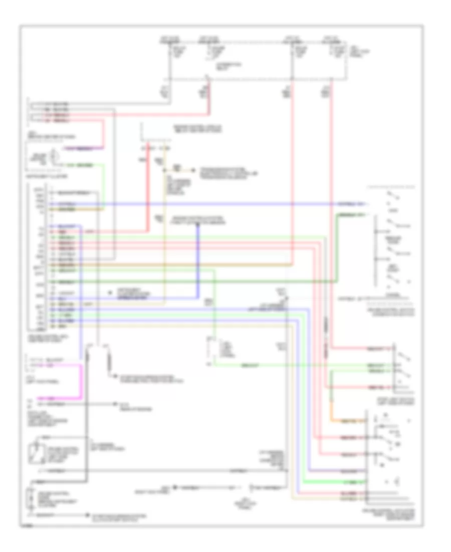
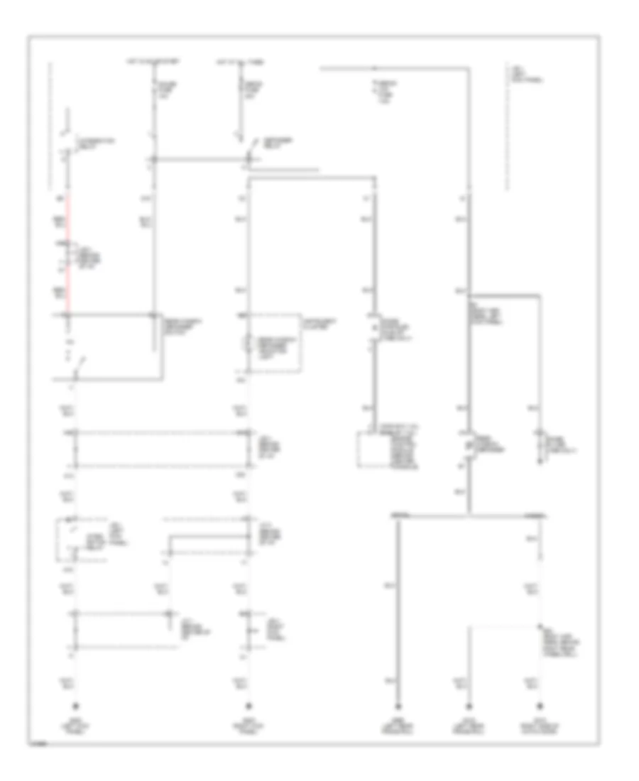
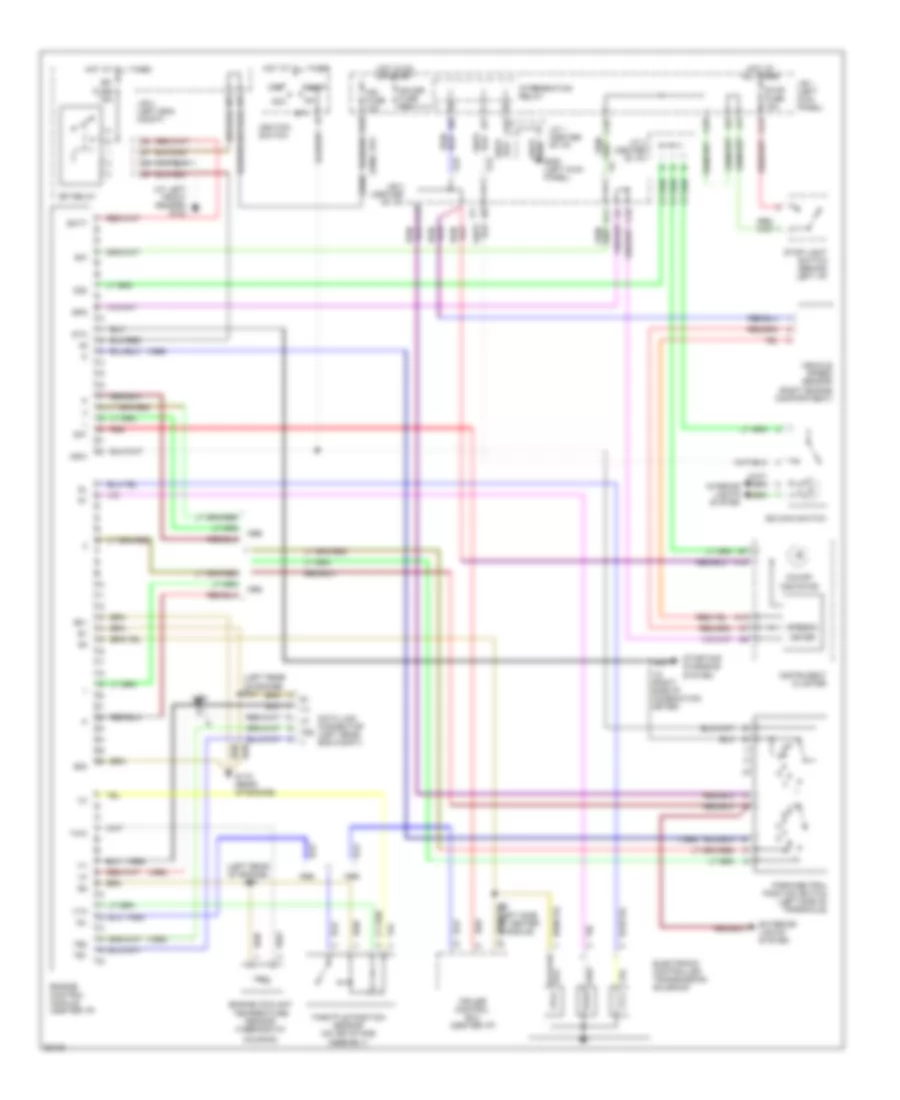
TRANSMISSION
Transmission Wiring Diagram for Toyota Corolla 1996
List of elements for Transmission Wiring Diagram for Toyota Corolla 1996:
- (1995)
- (1996)
- (at left front fender) g100
- (left rear of engine)
- (left rear of engine) e18
- A10
- A13
- A14
- A15
- A18
- A19
- Acc
- B/k
- Batt
- C10
- C12
- C13
- C18
- Cruise control ecu (center i/p)
- D11
- Data link connector (left rear eng compt)
- E01
- E02
- E17
- Efi fuse 15a
- Efi relay
- Electronic controlled transmission solenoid
- Engine control module (center i/p)
- Engine coolant
- Exterior lights system
- G115 (rear of engine)
- G15
- G200 (left kick panel)
- Gauge fuse 10a
- Hot at all times
- Hot in on or start
- Housing)
- I18 (right side of combination meter)
- I32 (left side of center console)
- Idl
- Ign fuse 10a
- Ignition switch
- Indicator
- Instrument cluster
- Intergration relay
- Interior lights system
- J/b 1 (left kick panel)
- J/b 2 (left eng compt)
- J/b 3 (center of i/p)
- J/c 1 (center of i/p)
- J/c 3 (center of i/p)
- Meter
- Nsw
- O/d main switch
- O/d off
- Od1
- Od2
- Off
- Park/neutral position switch (left side of transaxle)
- Red
- Red/
- Spd
- Speedo-
- St1
- Sta
- Start
- Starting/ charging system
- Stop fuse 15a
- Stop light switch (behind left i/p)
- Te1
- Te2
- Temperature sensor (thermostat
- Throttle position sensor (on air intake assembly)
- Thw
- Vehicle speed sensor (right engine compartment)
- Vta
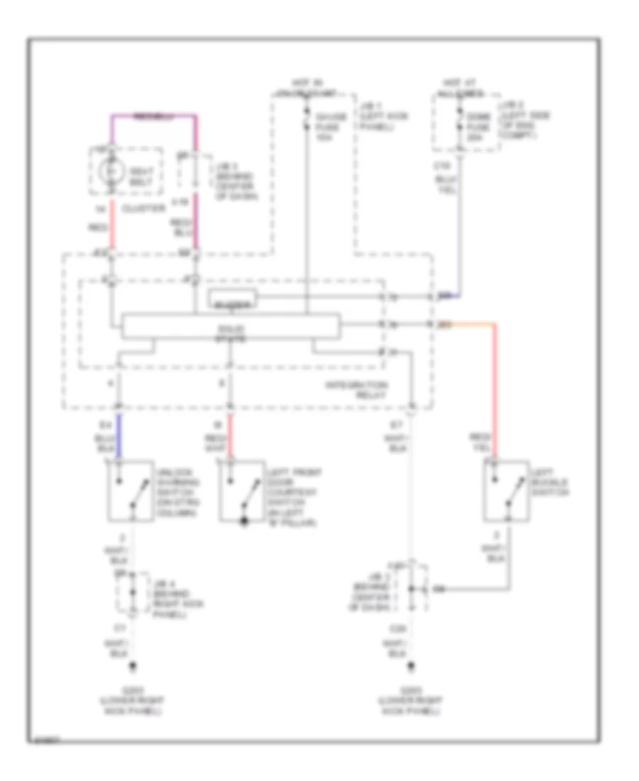
WARNING SYSTEMS
Warning System Wiring Diagrams for Toyota Corolla 1996
List of elements for Warning System Wiring Diagrams for Toyota Corolla 1996:
- A13
- A19
- Buzzer
- C10
- C20
- Cluster
- Dome fuse 20a
- G203 (lower right kick panel)
- Gauge fuse 10a
- Hot at all times
- Hot in on or start
- Integration
- J/b 1 (left kick panel)
- J/b 2 (left side of eng compt)
- J/b 3 (behind center of dash)
- J/b 4 (behind right kick panel)
- Left buckle switch
- Left front door courtesy switch (in left "b" pillar)
- Red
- Relay
- Seat belt
- Solid state
- Unlock warning switch (on strg column)
WIPER/WASHER
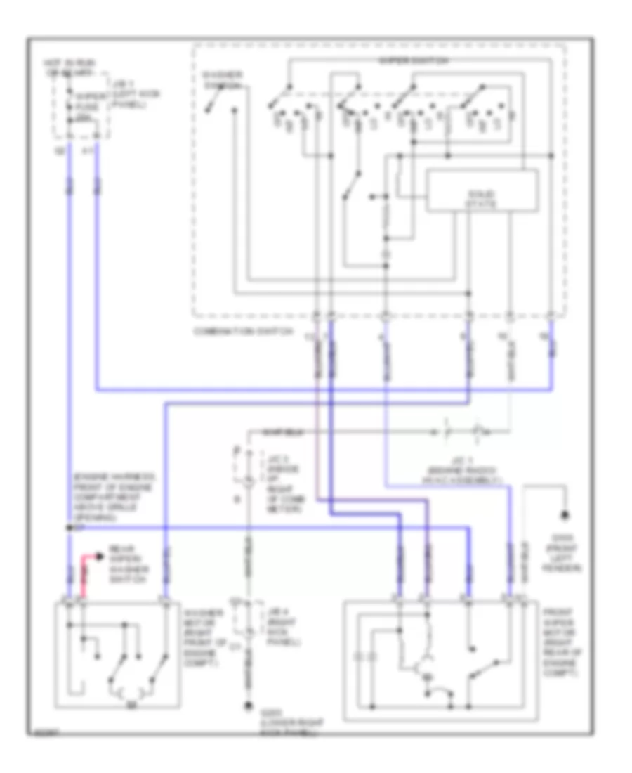
Front Wiper/Washer Wiring Diagram for Toyota Corolla 1996
List of elements for Front Wiper/Washer Wiring Diagram for Toyota Corolla 1996:
- (engine harness, front of engine compartment above grille opening) e7
- Combination switch
- Front wiper motor (right rear of engine compt)
- G100 (front left fender)
- G203 (lower right kick panel)
- Hot in run or start
- Int
- J/b 1 (left kick panel)
- J/b 4 (right kick panel)
- J/c 1 (behind radio/ hvac assembly)
- J/c 3 (inside i/p, right of comb meter)
- Off
- Pnk
- Rear wiper/ washer switch
- Solid state
- Washer motor (right front of engine compt)
- Washer switch
- Wiper fuse 20a
- Wiper switch
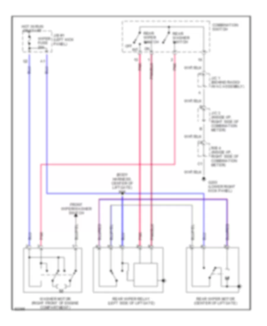
Rear Wiper/Washer Wiring Diagram for Toyota Corolla 1996
List of elements for Rear Wiper/Washer Wiring Diagram for Toyota Corolla 1996:
- (body harness, center of liftgate) b28
- Combination switch
- Front wiper/washer switch
- G203 (lower right kick panel)
- Hot in run or start
- Int
- J/b #1 (left kick panel)
- J/c 1 (behind radio/ hvac assembly)
- J/c 3 (inside i/p, right side of combination meter)
- Off
- Pnk
- R/b 4 (inside i/p, right side of combination meter)
- Rear washer switch
- Rear wiper motor (center of liftgate)
- Rear wiper relay (left side of liftgate)
- Rear wiper switch
- Washer motor (right front of engine compartment)
- Wiper fuse 20a

 Čeština
 Dansk
Dansk Deutsch
 Ελληνικά
 English
 English
 Español
 Suomi
Suomi Français
 עברית
עברית Hrvatski
 Magyar
 Italiano
 日本語
日本語 한국어
한국어 Nederlands
 Polski
 Português
 Português
 Română
 Русский
 Slovenčina
 Slovenščina
 Svenska
 Türkçe
 中文 (中国)