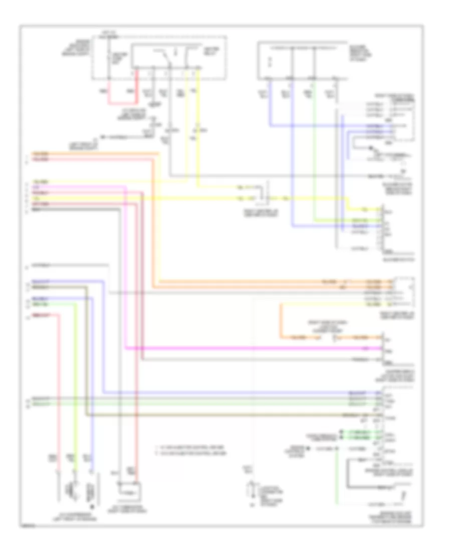
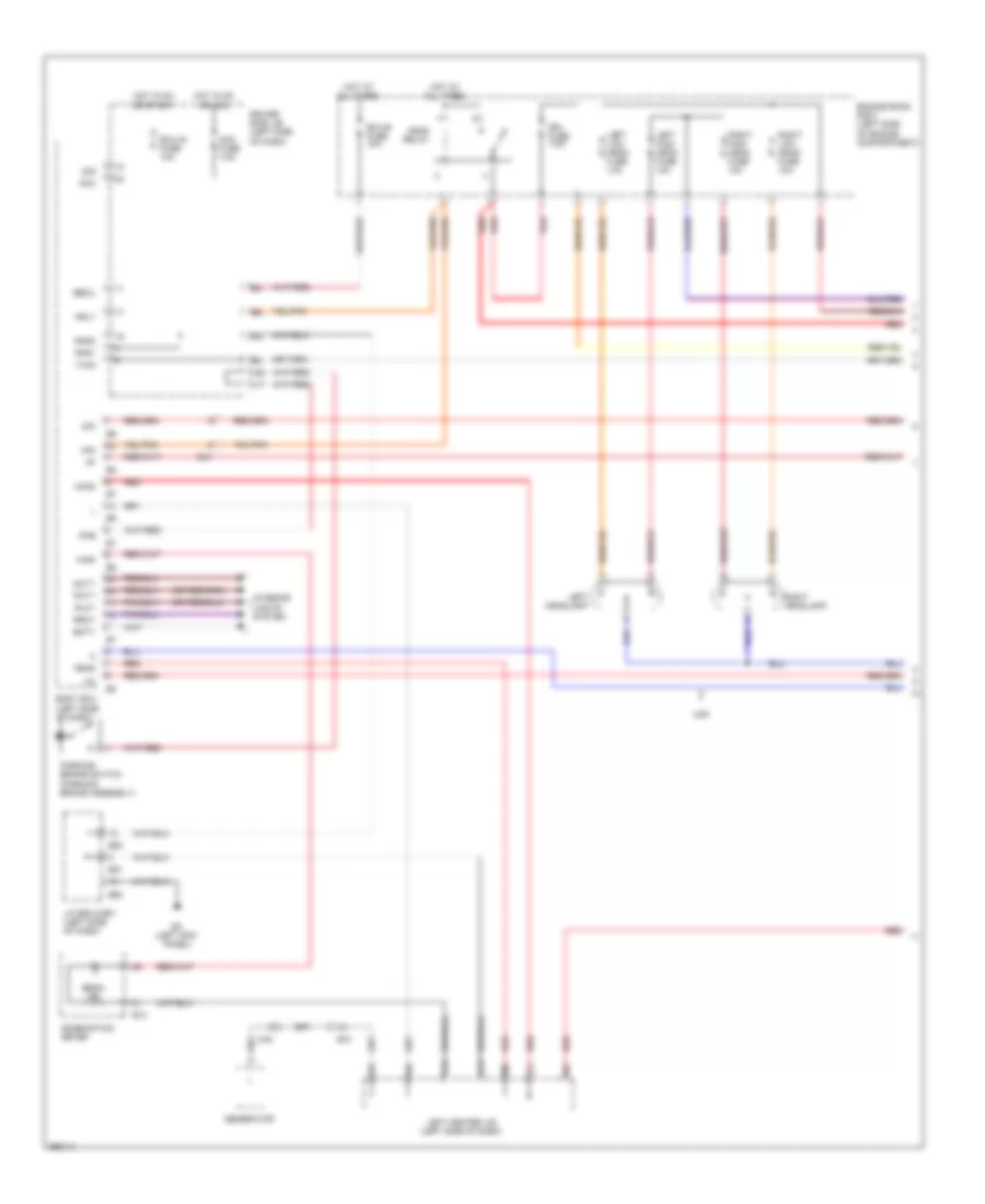
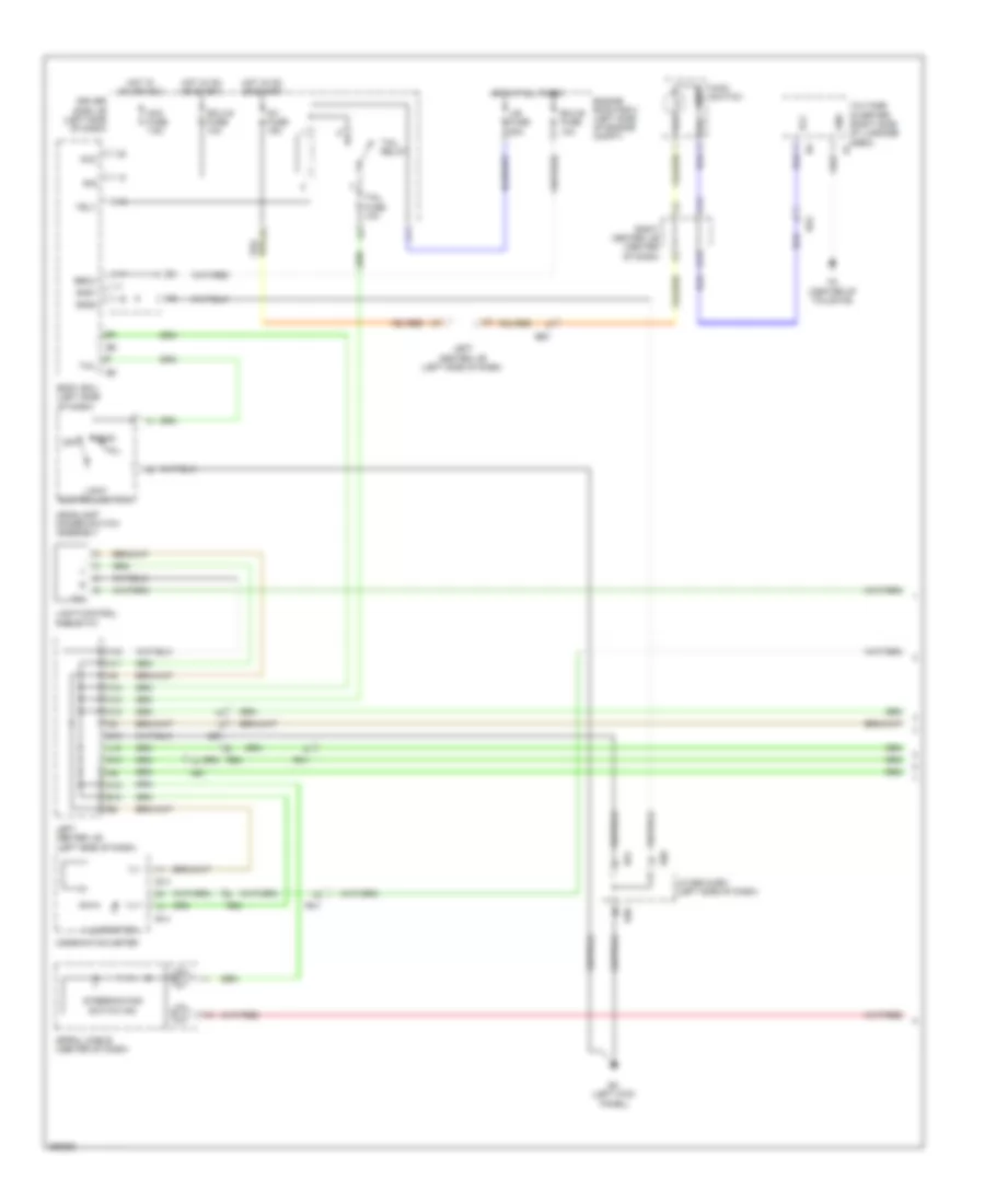
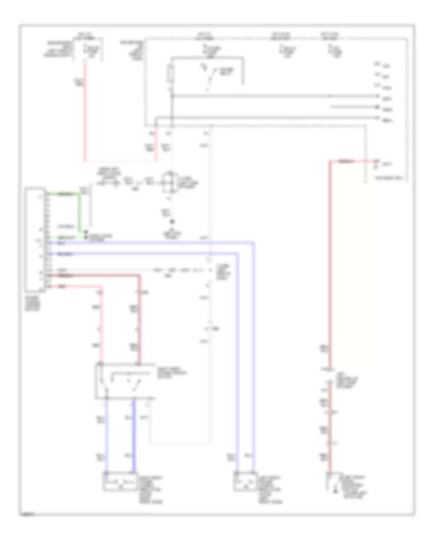
AIR CONDITIONING
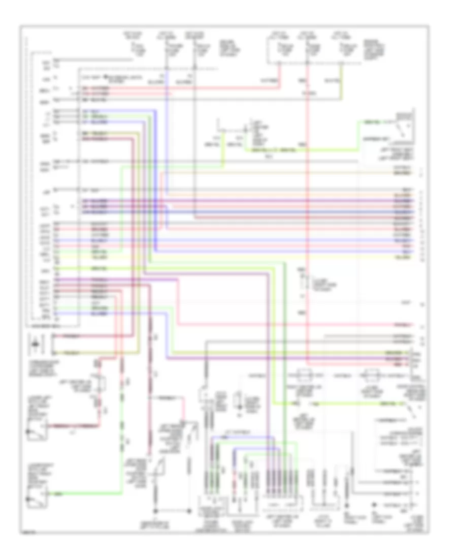
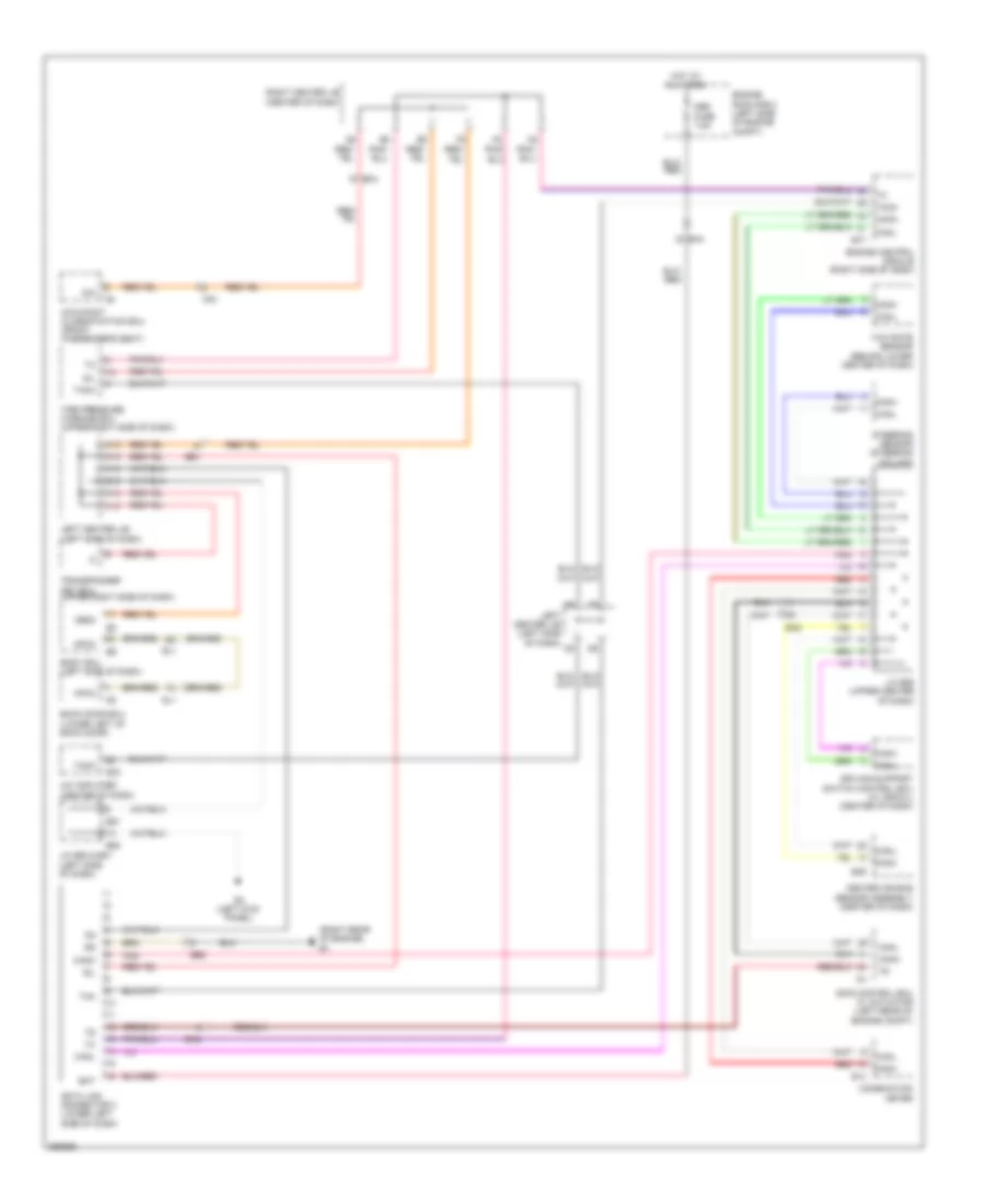
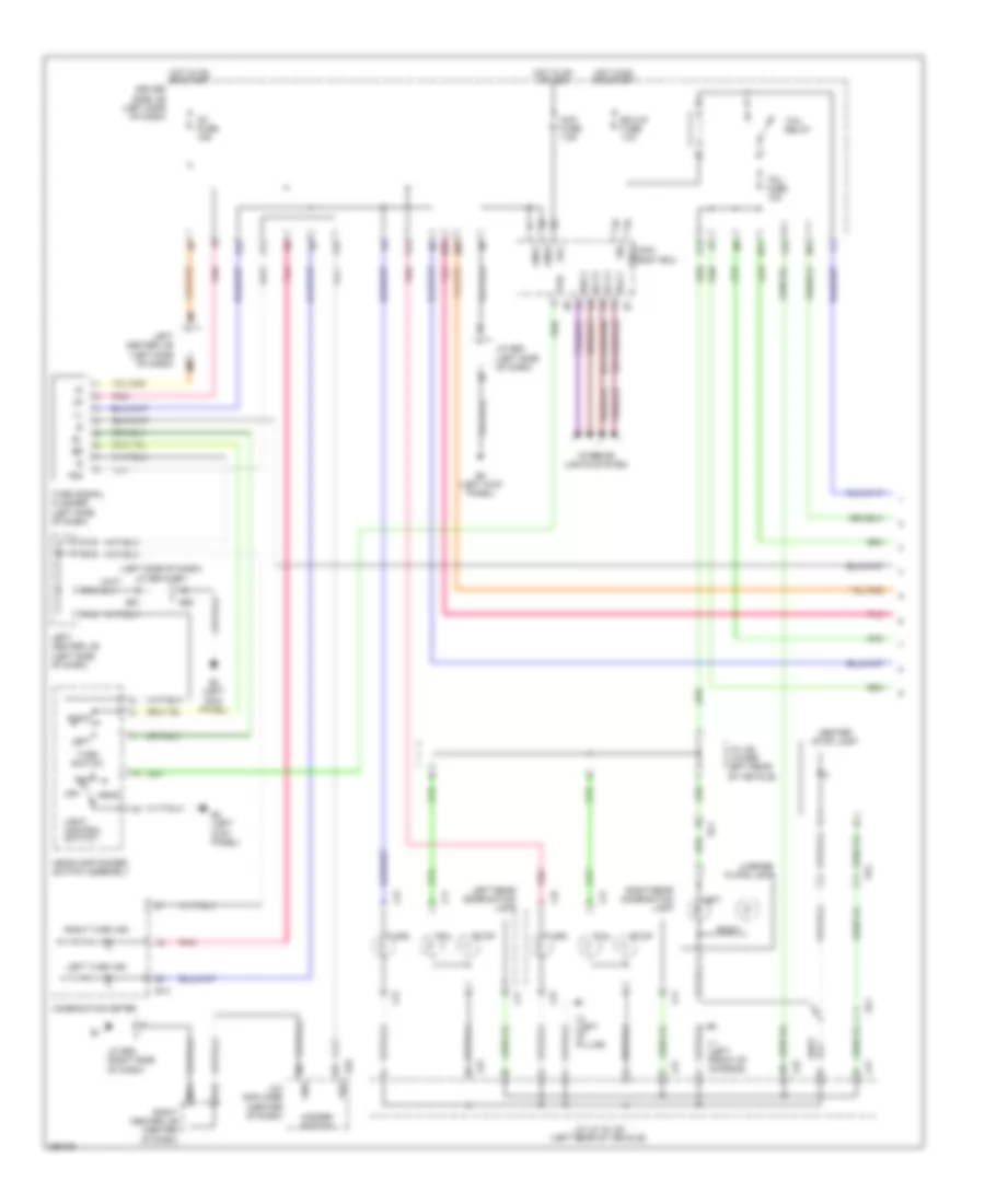
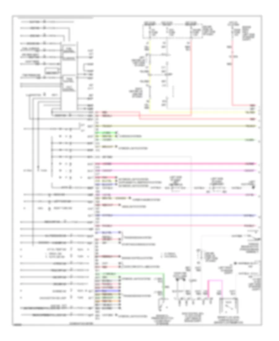
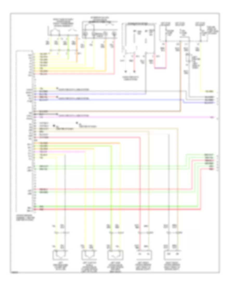
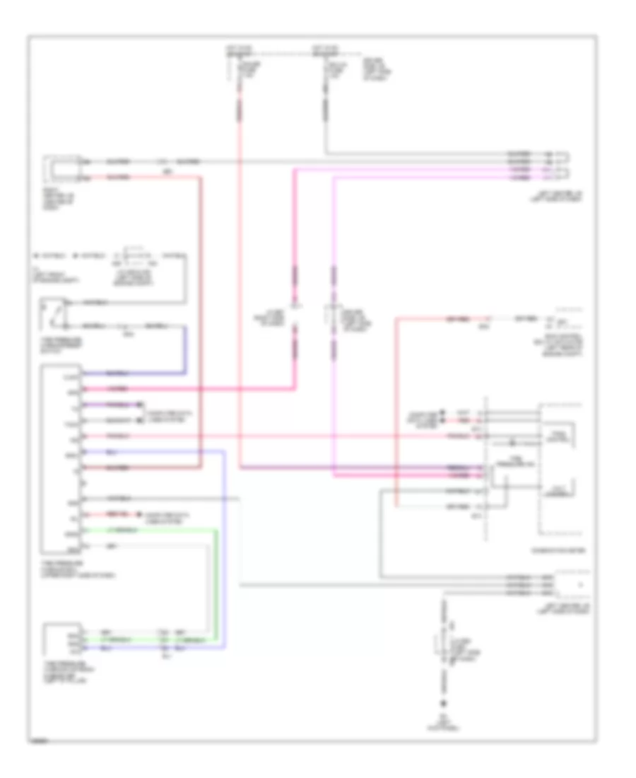
Automatic A/C Wiring Diagram (1 of 2) for Toyota FJ Cruiser 2013
 https://portal-diagnostov.com/license.html
Automotive Electricians Portal FZCO
Automotive Electricians Portal FZCO
https://portal-diagnostov.com/license.html
https://portal-diagnostov.com/license.html
Automotive Electricians Portal FZCO
Automotive Electricians Portal FZCO
List of elements for Automatic A/C Wiring Diagram (1 of 2) for Toyota FJ Cruiser 2013:
- (left side of dash) left center j/b
- A/c amplifier (center of dash)
- Ac1
- Act
- All times
- Ambient temperature sensor (behind front grille)
- Amc
- Amh
- Anti-theft system
- Be1
- Be2
- Blw
- Damper servo motor (air mix) (right side of dash)
- Damper servo motor (air vent mode) (right side of dash)
- Def
- Defogger system
- Driver side j/b (left side of dash)
- E20
- E32
- E33
- Ea1
- Ea6
- Ecu-b fuse 10a
- Engine room r/b 2 (left side of engine compt)
- Exterior lights system
- Face
- Frs
- Gnd
- Haz
- Hot at
- Hot in on
- Ig+
- Ig1 fuse 15a
- Ill+
- Ill-
- Instrument cluster system
- Interior lights system
- J/c a28 (left front of engine compt)
- Lock
- Mg clt
- Mgc
- Or start
- Paon
- Passenger's seat belt warning light air bag on/off indicator & front hazard switch, security indicator, rear window defogger switch,
- Pbew
- Pnk
- Pressure switch (right front of engine compt)
- Psw
- Rdfg
- Rec
- Relay
- S5-1
- Sg-1
- Sg-2
- Sg-3
- Sg-4
- Spd
- Sw-
- Taco
- Tam
- Tamg
- Tamo
- Tpm
- Warning systems
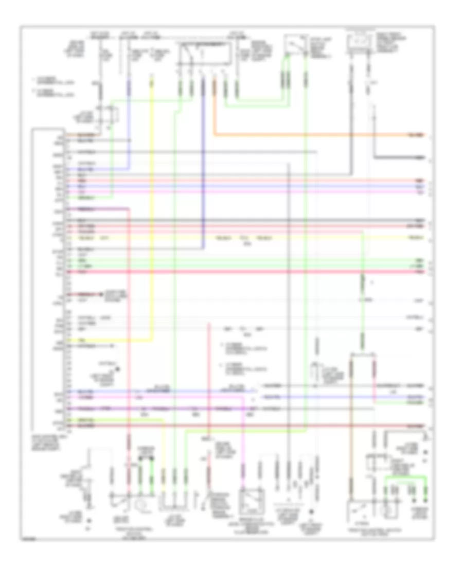
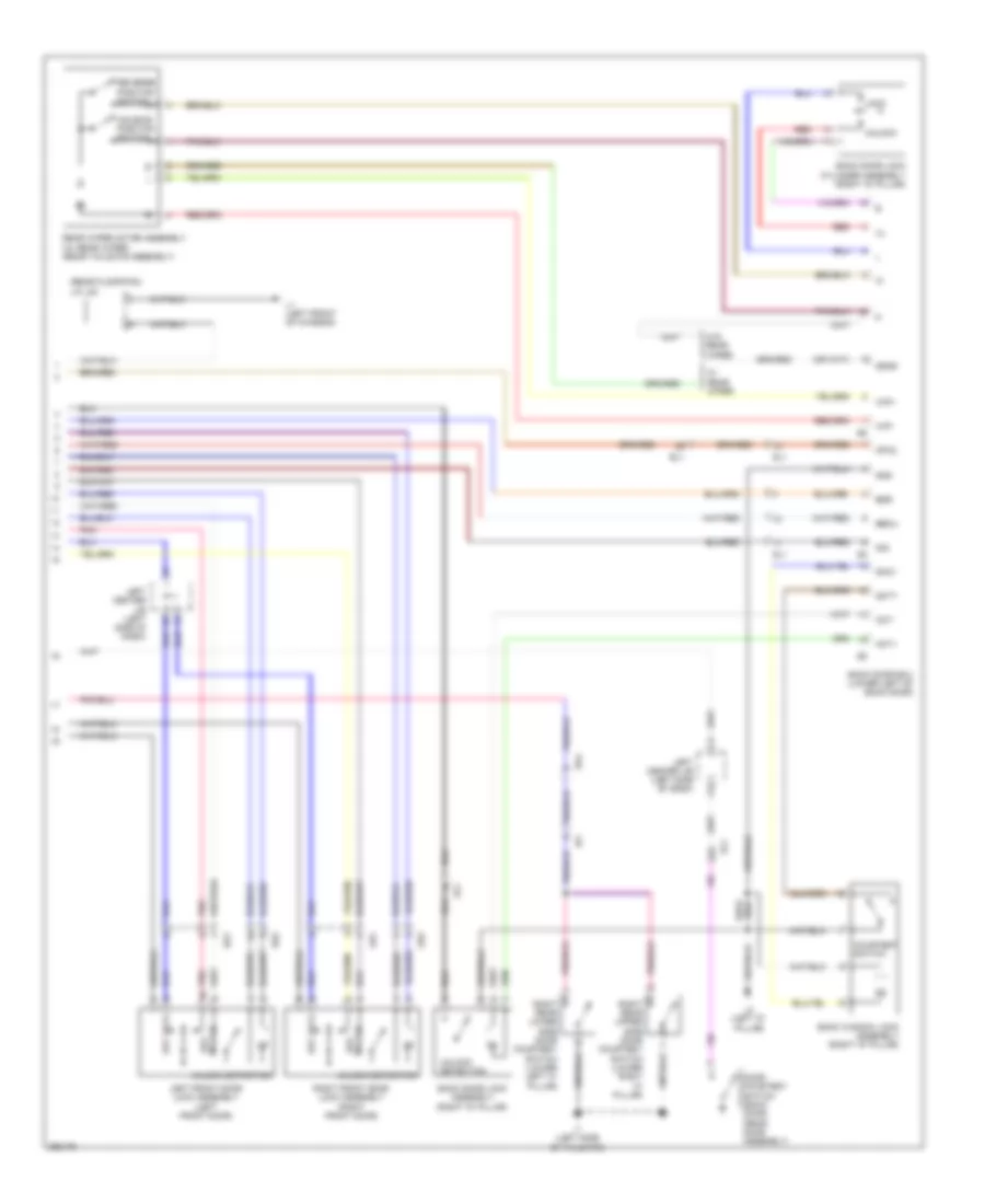
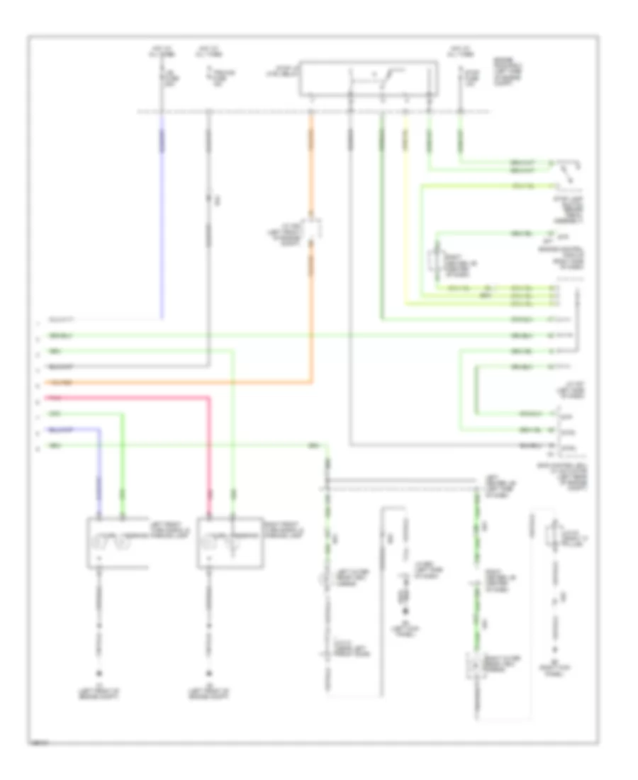
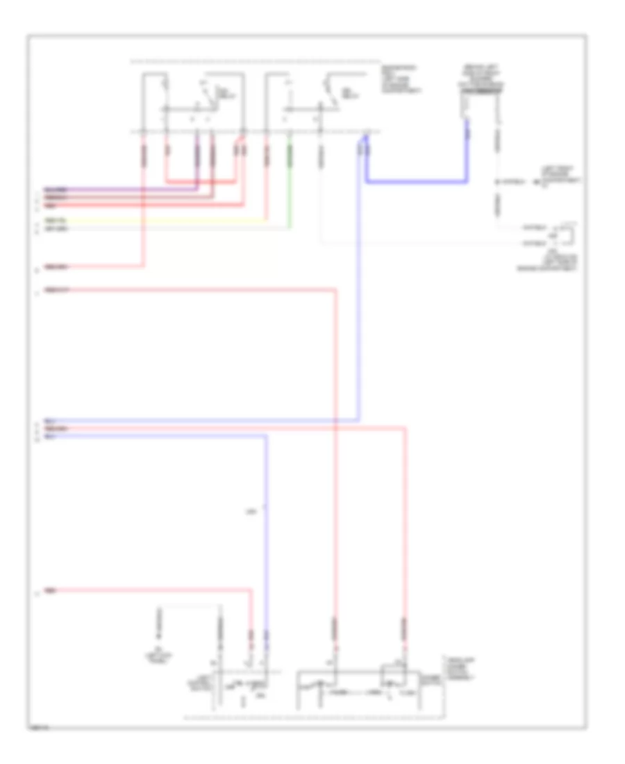
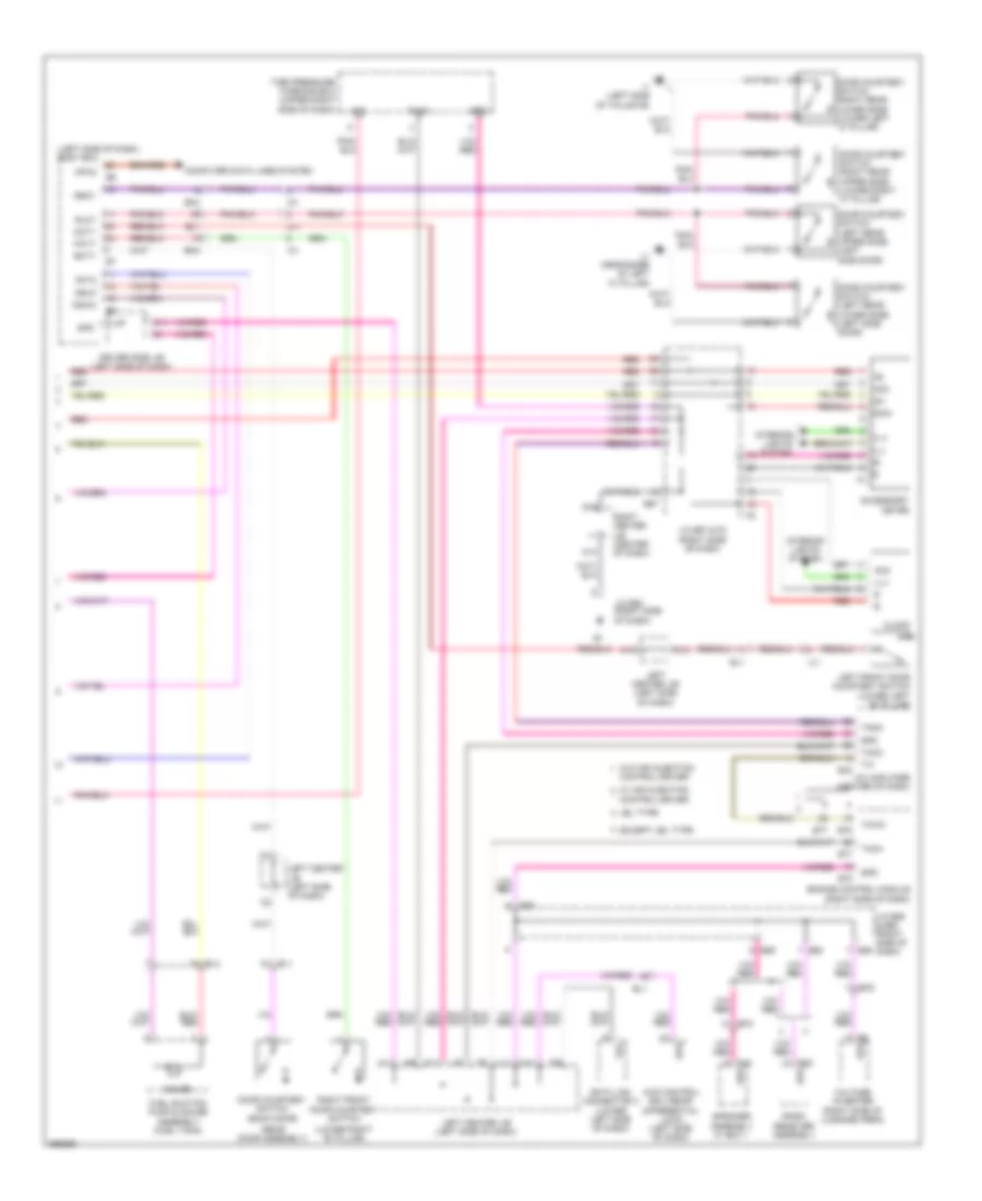
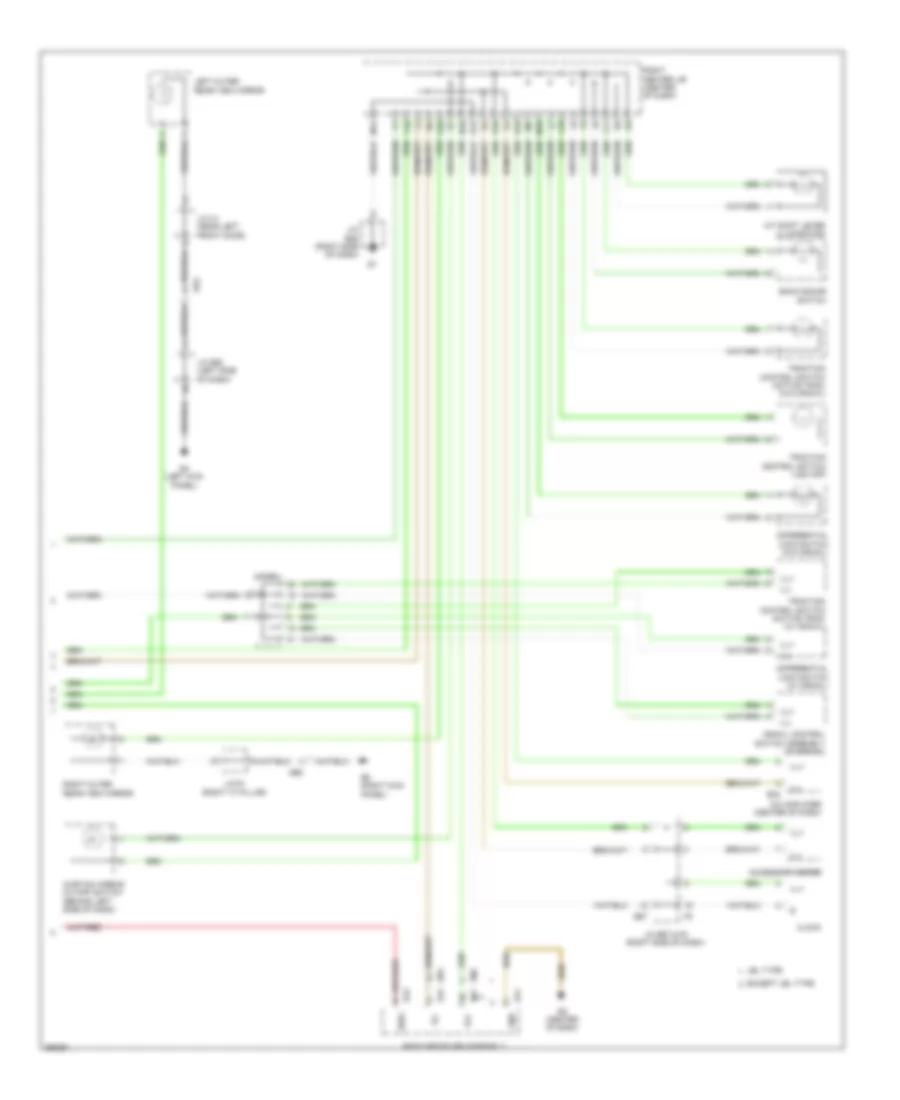
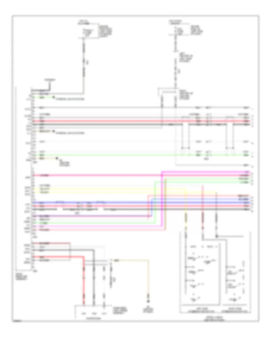
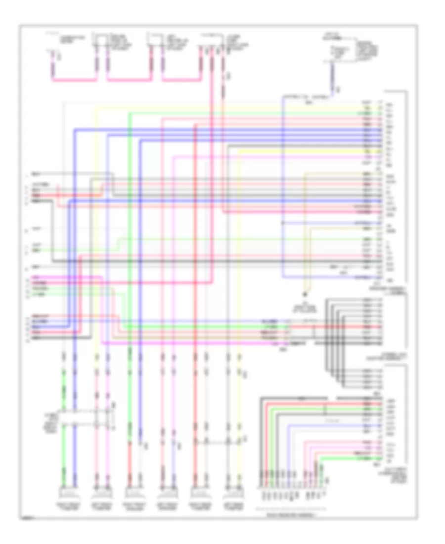
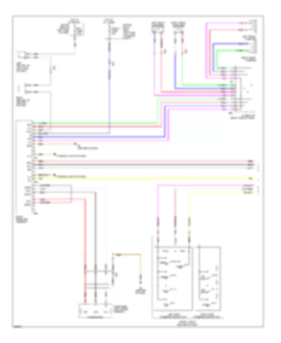
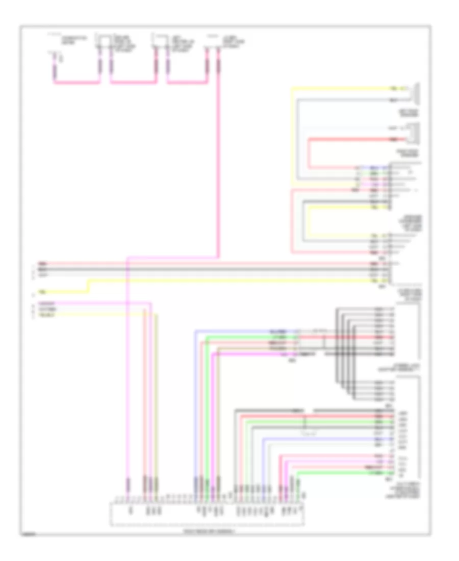
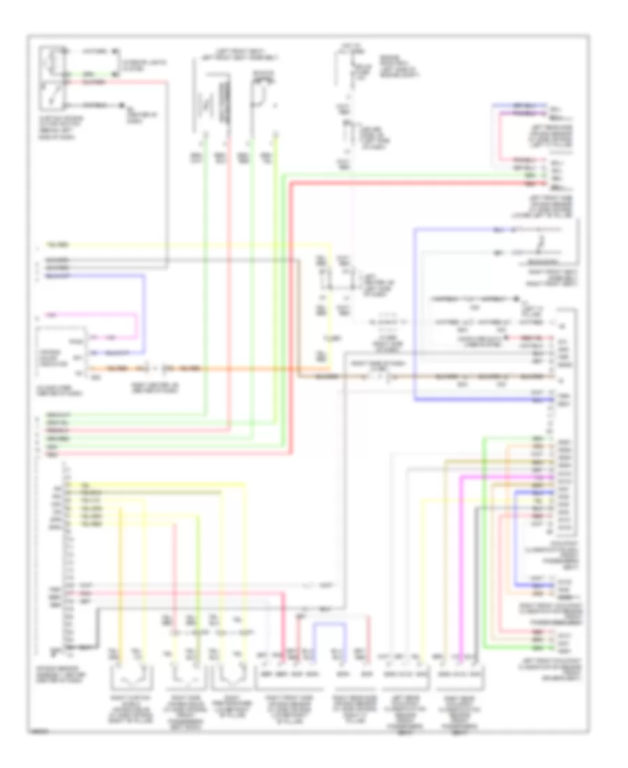
Automatic A/C Wiring Diagram (2 of 2) for Toyota FJ Cruiser 2013
List of elements for Automatic A/C Wiring Diagram (2 of 2) for Toyota FJ Cruiser 2013:
- (right side of dash) j/c e55 & e56
- (right side of dash) junction connector e57
- A/c compressor (left front of engine)
- A/c thermistor (right side of dash)
- A1 (left front of engine compt)
- A29
- A30
- Ac1
- Act
- All times
- B48
- B49
- Blower motor (behind right side of dash)
- Blower resistor (right side of dash)
- Blower switch
- Can h
- Can l
- Clutch magnetic
- Computer data lines system
- Damper servo motor (air inlet) (right side of dash)
- E4 (left kick panel)
- E55
- E56
- E77
- E78
- Ea4
- Ee1
- Engine control module (right side of dash)
- Engine controls system
- Engine coolant temperature sensor (top rear of engine)
- Engine room r/b 2 (left side of engine compt)
- Ethw
- F11
- Frs
- Gnd
- H11
- H15
- Heater
- Heater fuse 60a
- Hot at
- Ig+
- J/c a29 & a30 (left side of engine compt)
- Junction connector e52 (right side of dash)
- M14
- Rec
- Red
- Relay
- Rh1
- Right center j/b (center of dash)
- Rlo
- Sensor lock
- Tach
- Thw
- Thwo
- W/ air injector control driver
- W/o air injector control driver
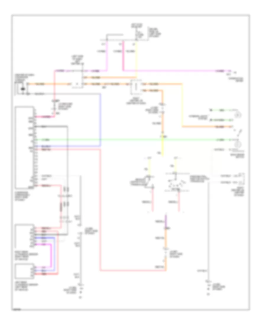
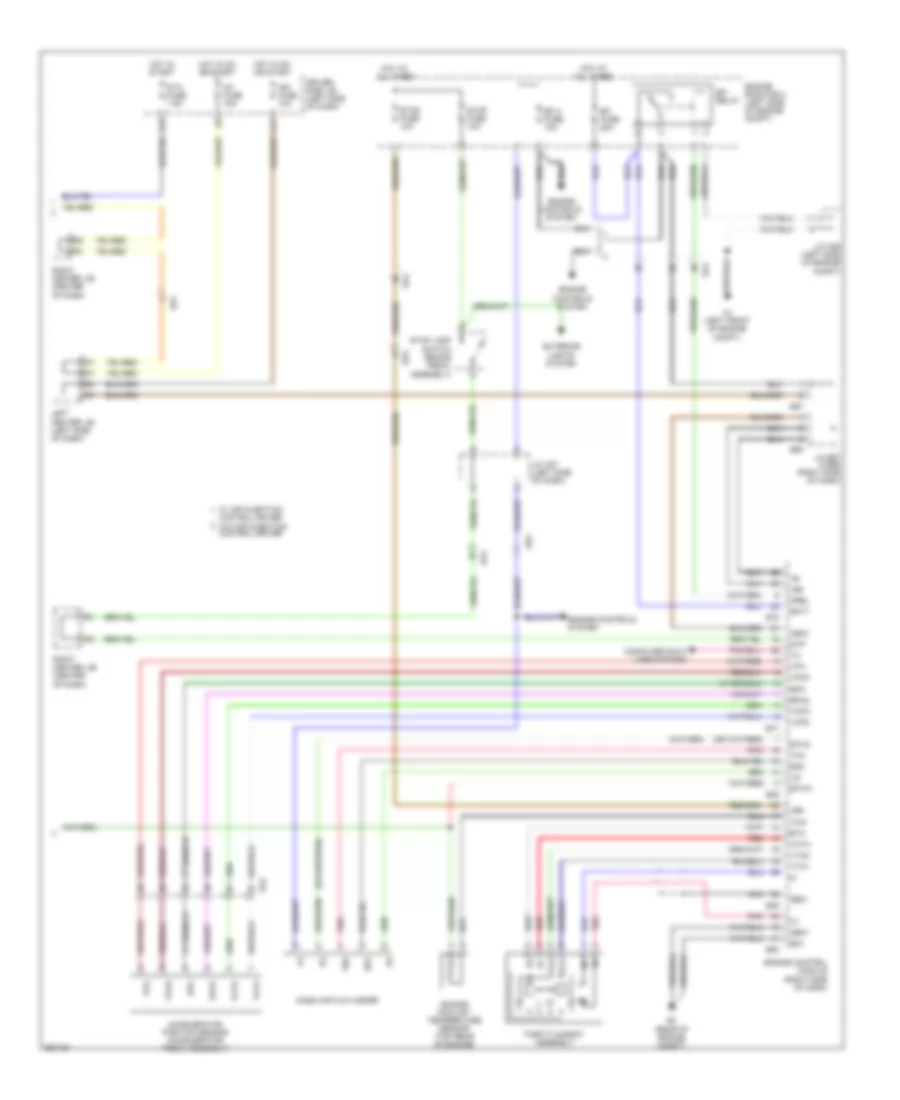
ANTI-LOCK BRAKES
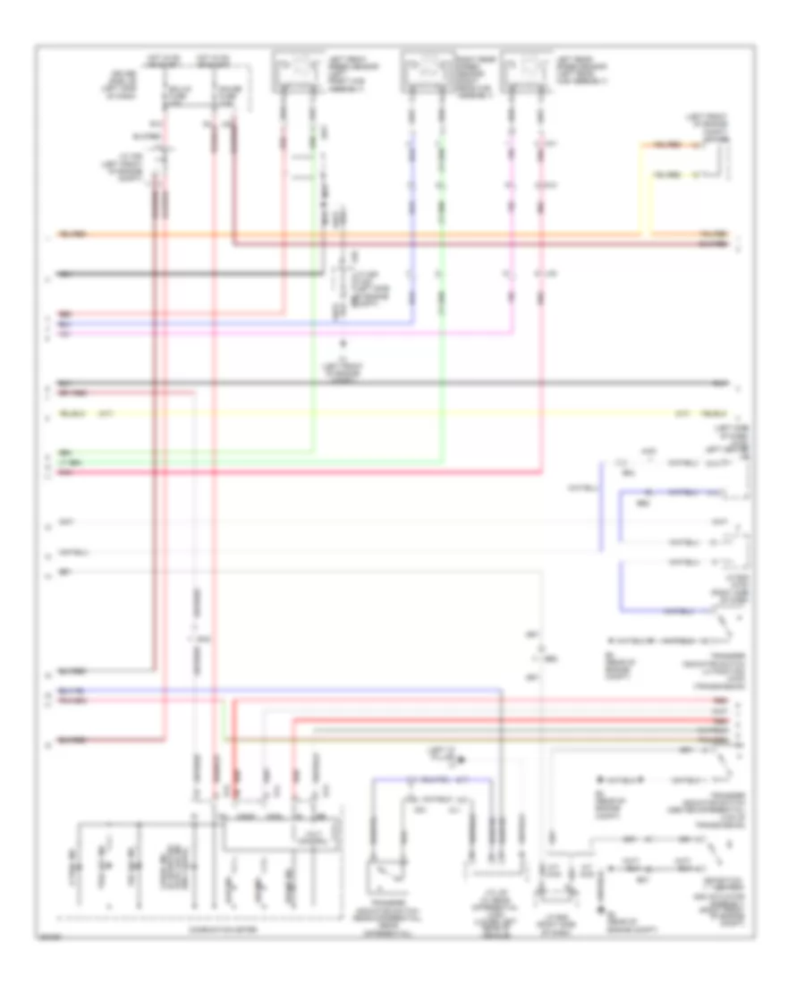
Anti-lock Brakes Wiring Diagram (1 of 3) for Toyota FJ Cruiser 2013
List of elements for Anti-lock Brakes Wiring Diagram (1 of 3) for Toyota FJ Cruiser 2013:
- (4wd)
- (a/t)
- +bm1
- +bm2
- +bs
- A-trac
- A1 (left front of engine compt)
- A2 (left front of engine compt)
- A29
- A30
- Abs mtr fuse 40a
- Abs sol fuse 30a
- Atrc
- Av1
- Be2
- Brake fluid level warning switch (brake fluid reservoir)
- Canh
- Canl
- Computer data lines system
- Csw
- Differential lock
- Differential lock & w/o crawl
- Driver side j/b (left side of dash)
- Ea2
- Engine room r/b 3 (left side of engine compt)
- Exi
- Exi3
- Exi4
- Fl+
- Fl-
- Fr+
- Fr-
- Gnd1
- Gnd2
- Gnd3
- Hot at all times
- Hot in on or start
- Ig1
- Ig2
- Ign fuse 10a
- Interior lights system
- J/c a27 (left side of dash)
- J/c a29 & a30 (left side of engine compt)
- J/c a29 (left side of engine compt)
- J/c e52 (right side of dash)
- J15
- J20
- L13
- L14
- La2
- Lbl
- M14
- Nca
- Neo
- Parking brake switch (parking brake assembly)
- Pkb
- Pnk
- Red
- Right center j/b (center of dash)
- Right front speed sensor (at right front hub assembly)
- Rl+
- Rl-
- Rr+
- Rr-
- Skid control ecu w/ actuator (left rear of engine compt)
- Sp1
- Stop
- Stop fuse 10a
- Stop lamp switch (brake pedal assembly)
- Stop lp ctrl relay
- Stp
- Stp2
- Traction control switch (active trac)
- Traction control switch (w/ vsc off)
- Vsc off switch
- W/ rear
- W/ rear differential lock
- W/ rear differential lock & w/ crawl
- W/o rear
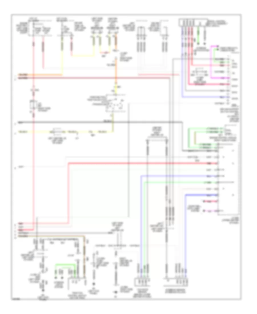
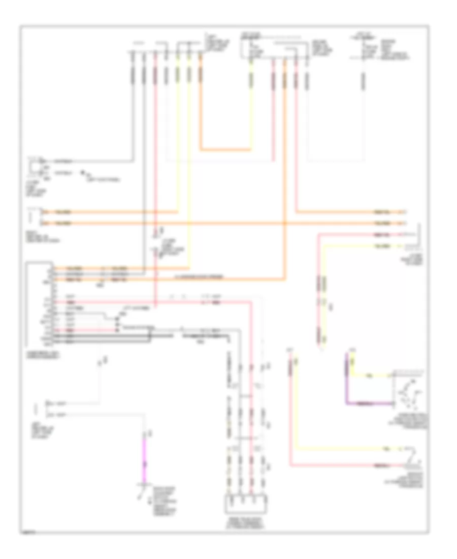
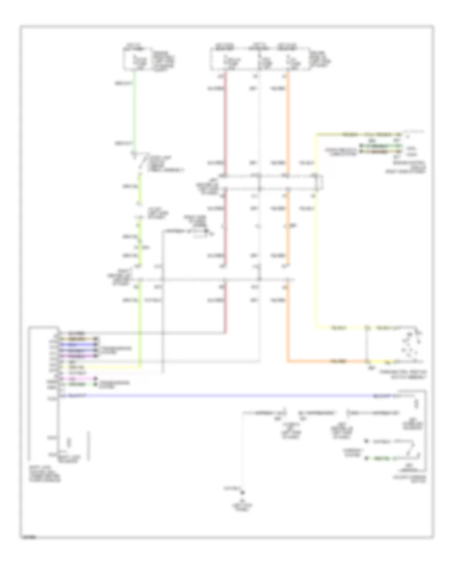
Anti-lock Brakes Wiring Diagram (2 of 3) for Toyota FJ Cruiser 2013
List of elements for Anti-lock Brakes Wiring Diagram (2 of 3) for Toyota FJ Cruiser 2013:
- (a/t)
- (left "d" pillar) l2
- (left front of engine compt) j/c a28
- (left side of dash) (4wd) left center j/b
- 4wd
- A-trac ind
- A/t 4wd
- A1 (left front of engine compt)
- A29
- A30
- Abs ind
- Add actuator assembly (right front of engine compt)
- Auto lsd ind (w/o crawl)
- Aw1
- B3 (rear of engine compt)
- Bd1
- Be2
- Brake ind
- Canh
- Canl
- Combination meter
- Crawl ind (if equipped)
- D14
- Detection switch
- Driver side j/b (left side of dash)
- E12
- E13
- E14
- Ea2
- Ecu-ig fuse 10a
- F13
- Gauge fuse 7.5a
- Hot in on or start
- Ig+
- J/c a28 (left front of engine compt)
- J/c a29 & a30 (left side of engine compt)
- J/c b45 (4wd) (right side of dash)
- J/c b46 (right side of dash)
- J/c l20 (w/ rear differential lock) (lower left rear of vehicle)
- La2
- Left front speed sensor (left front hub assembly)
- Left rear speed sensor (left rear hub assembly)
- M/t 4wd
- Nca
- Od1
- Ol1
- Ol2
- Ox1
- Pnk
- Red
- Right rear speed sensor (right rear hub assembly)
- Slip ind
- Trac off ind
- Transfer indicator switch (center differential) (top of transmission)
- Transfer indicator switch (l4 position) (4wd) (transmission)
- Transfer indicator switch (rear differential) (rear differential)
- Volt control
- Vsc off ind
Anti-lock Brakes Wiring Diagram (3 of 3) for Toyota FJ Cruiser 2013
List of elements for Anti-lock Brakes Wiring Diagram (3 of 3) for Toyota FJ Cruiser 2013:
- (a/t)
- (center of dash) (a/t) right center j/b
- (center of dash) right center j/b
- (left side of dash)
- (left side of dash) (a/t) left center j/b
- (left side of dash) left center j/b
- (right side of dash)
- 2-l
- 4-d
- A/t
- Atrc
- B14
- Bat
- Be1
- Canh
- Canl
- Computer data lines system
- Crawl control switch assembly (w/ crawl)
- D15
- Dome fuse 10a
- Driver side j/b (left side of dash)
- Driving support switch control ecu (w/ crawl) (center of dash)
- E15
- E20
- E4 (left kick panel)
- E50
- E51
- E59
- E60
- E77
- Ea2
- Ecu-b fuse 10a
- Ee1
- Engine control module (right side of dash)
- Engine room r/b 3 (left side of engine compt)
- Ess
- Gnd
- Hot at all times
- Hot in on or start
- Ig1 fuse 15a
- Ill+
- Ill-
- Interior lights system
- J/c e50 & e51 (left side of dash) e50
- J/c e51 & e50 (left side of dash)
- J/c e52 (right side of dash)
- J/c e57
- J/c e59 & e60 (right side of dash)
- J/c e67 (right side of dash)
- J/c e86 (upper center of dash)
- J/c m5
- K15
- L15
- Left center j/b
- Left center j/b (left side of dash)
- M14
- N15
- Park/neutral position switch (a/t) (transaxle)
- Pnk
- Re2
- Re4
- Red
- Right center j/b (center of dash)
- Rm1
- Steering sensor (steering column)
- Swi1
- Swi2
- Swi3
- Swi4
- Swo1
- Swo2
- Swo3
- Swo4
- Traction control switch (active trac)
- Yaw rate sensor (behind lower center of dash)
ANTI-THEFT
Forced Entry Wiring Diagram (1 of 2) for Toyota FJ Cruiser 2013
List of elements for Forced Entry Wiring Diagram (1 of 2) for Toyota FJ Cruiser 2013:
- (lower left "b" pillar) left front door courtesy switch
- (lower right "b" pillar) right front door courtesy switch
- (right side of dash)
- Acc
- Acc fuse 7.5a
- Act+
- Act-
- Actd
- B10
- Bcty
- Bdr1
- Becu
- Buckle switch
- Bzr
- Bzr2
- D15
- Dbkl
- Dcty
- Dome fuse 10a
- Door control receiver (right side of dash)
- Door lock control switch
- Dr/lck fuse 20a
- Driver side j/b (left side of dash)
- E4 (left kick panel)
- E5 (right kick panel)
- E50
- E51
- Ea2
- Ecu-b fuse 10a
- Ecu-ig fuse 10a
- Ek4
- El1
- El2
- Engine room r/b 2 (left side of engine compt)
- Exterior lights system
- F11
- F12
- G11
- G14
- Ge1
- Ge2
- Gnd
- Gnd1
- Gnd2
- H11
- H12
- H14
- Haz
- He1
- He2
- Hot at all times
- Hot in on or acc
- Hot in on or start
- Ik1
- J/c e50 & e51 (left side of dash)
- J/c e52 (right side of dash)
- J/c e67
- J/c e67 (right side of dash)
- J/c g1 (right "c" pillar)
- J/c h1 (near left front door)
- J1 (near base of left "c" pillar)
- J14
- Jl1
- Ksw
- L18
- Left center j/b (left side of dash)
- Left front seat inner belt (left front seat)
- Left rear lower side door courtesy switch (left side door)
- Left rear upper side door courtesy switch (left side door)
- Lsr
- Lswd
- Lswp
- M12
- M14
- Main body ecu
- Mpx2
- N12
- Pcty
- Pnk
- Power fuse 30a
- Power window master switch
- Prg
- Rda
- Red
- Right center j/b (center of dash)
- Rlcy
- Rrcy
- Sig
- Ul1
- Ul2
- Ul3
- Unlock warning switch
- Wireless door lock buzzer (left side of engine compt)
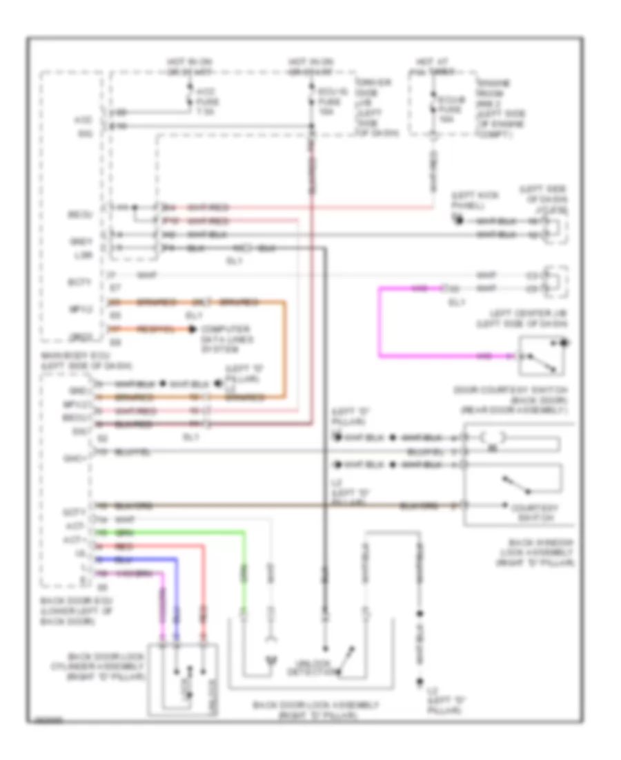
Forced Entry Wiring Diagram (2 of 2) for Toyota FJ Cruiser 2013
List of elements for Forced Entry Wiring Diagram (2 of 2) for Toyota FJ Cruiser 2013:
- (rear floor pan) j/c l22
- Act+
- Act-
- Back door ecu (lower left of back door)
- Back door lock assembly (right "d" pillar)
- Back door lock cylinder assembly (right "d" pillar)
- Back window lock assembly (right "d" pillar)
- Bdr
- Becu
- Courtesy switch
- Door courtesy switch (back door) (rear door assembly)
- Ek4
- El1
- Gcty
- Ge1
- Ge2
- Ghc+
- Gnd
- He1
- He2
- Housing position switch
- I1 (left side of tailgate)
- Ik1
- Key
- Key lock
- L1 (left front of chassis)
- L2 (left "d" pillar)
- Left center j/b (left side of dash)
- Left front door lock assembly (left front door)
- Lock
- Mpx2
- Pnk
- Rear wiper motor assembly (w/ rear wiper) (rear tailgate assembly)
- Red
- Reverse position switch
- Right front door lock assembly (right front door)
- Right rear lower side door courtesy switch (lower left "c" pillar)
- Right rear upper side door courtesy switch (lower right "c" pillar)
- Sgnd
- Sig
- Sl1
- Unlock
- Unlock detection
- W/ rear wiper
- W/o rear wiper
- Wip+
- Wip-
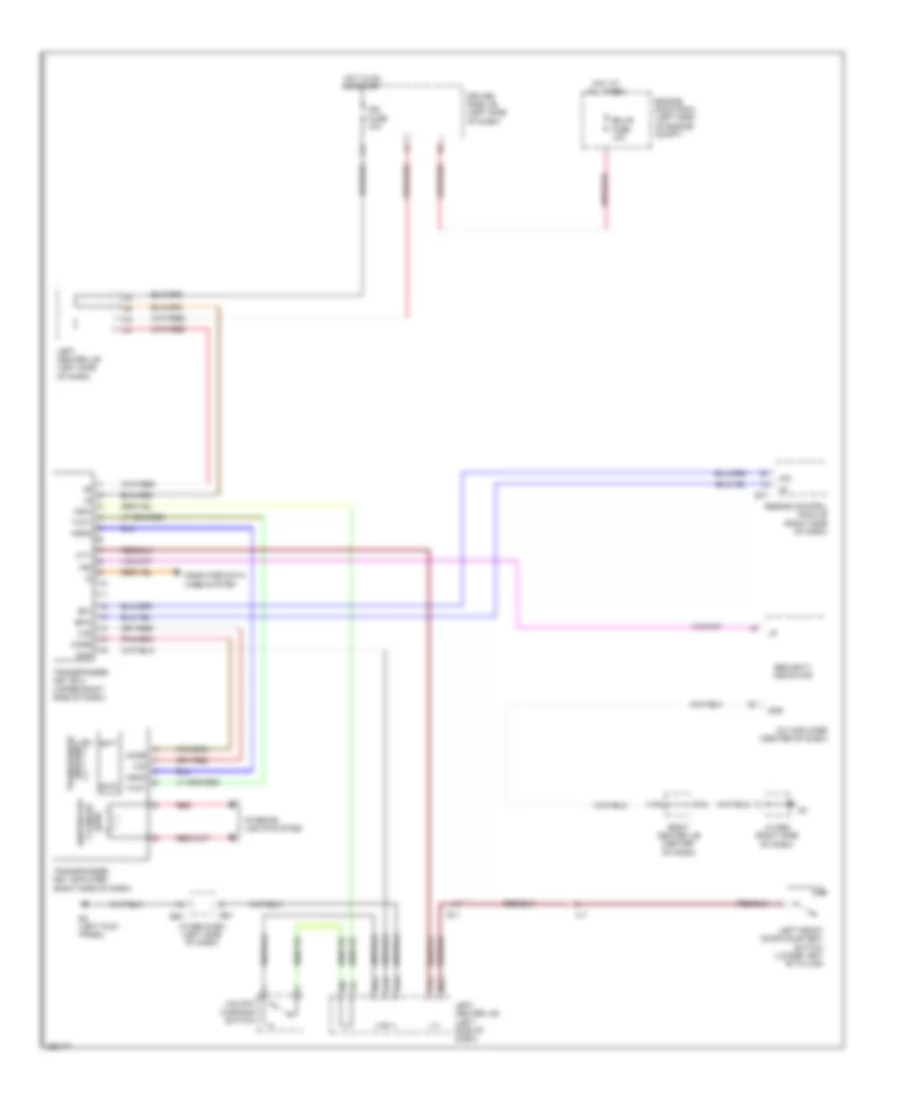
Immobilizer Wiring Diagram for Toyota FJ Cruiser 2013
List of elements for Immobilizer Wiring Diagram for Toyota FJ Cruiser 2013:
- A/c amplifier (center of dash)
- Agnd
- Ant1
- Ant2
- Code
- Computer data lines system
- Cty
- D15
- Driver side j/b (left side of dash)
- E4 (left kick panel)
- E50
- E51
- E77
- Ecu-b fuse 10a
- Efii
- Efio
- El1
- Engine control module (right side of dash)
- Engine room r/b 2 (left side of engine compt)
- Gnd
- H15
- Hot at all times
- Hot in on or start
- Ign fuse 10a
- Imi
- Imo
- Ind
- Interior lights system
- J/c e50 & e51 (left side of dash)
- J/c e52 (right side of dash)
- J11
- J12
- J15
- Jl1
- Key coil transponder
- Ksw
- Left center j/b (left side of dash)
- Left front door courtesy switch (lower left "b" pillar)
- Light cylinder ignition key
- M12
- M14
- N12
- Red
- Right center j/b (center of dash)
- Security indicator
- Transponder key amplifier (right side of dash)
- Transponder key ecu (upper right side of dash)
- Txct
- Unlock warning switch
- Vc5
BODY CONTROL MODULES
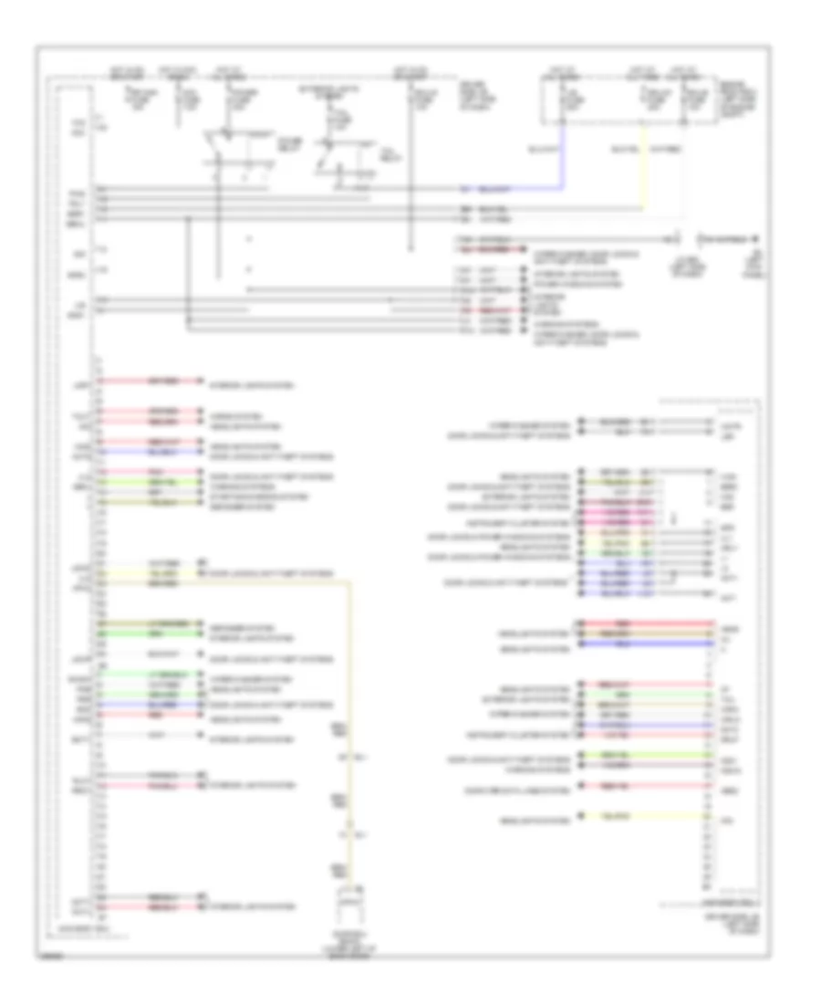
Body Control Modules Wiring Diagram for Toyota FJ Cruiser 2013
List of elements for Body Control Modules Wiring Diagram for Toyota FJ Cruiser 2013:
- (left kick
- A13
- Acc
- Acc fuse 7.5a
- Act+
- Act-
- Actd
- B10
- Bcty
- Bdr1
- Becu
- Bzr
- Bzr2
- Computer data lines system
- Dbkl
- Dcty
- Dcy2
- Defogger system
- Dim
- Door ecu (back) (lower left of back door)
- Door locks & anti-theft systems
- Door locks & power windows systems
- Dr/lck fuse 20a
- Driver side j/b (left side of dash)
- Drlp
- Ecu-b fuse 10a
- Ecu-ig fuse 10a
- El1
- Engine room r/b 2 (left side of engine compt)
- Exterior lights system
- F12
- Gnd1
- Gnd2
- H-on
- Haz
- Head
- Headlights system
- Hf2
- Hind
- Hon2
- Horns system
- Hot at all times
- Hot in acc or on
- Hot in on or start
- Hrly
- Ile
- Instrument cluster system
- Interior lights system
- J/b fuse 50a
- J/c e50 (left side of dash)
- J14
- K11
- Ksw
- Kswo
- L18
- Lmry
- Lsr
- Lswd
- Lswp
- Main body ecu
- Mpx2
- Obd2
- Panel)
- Pcty
- Pkb
- Pnk
- Power fuse 30a
- Power relay
- Power windows system
- Prg
- Pws
- Rda
- Red
- Rlcy
- Rr wsh fuse 15a
- Rrcy
- Rwsw
- Sig
- Sl1
- Spd
- Starting/charging system
- Tail
- Tail fuse 10a
- Tail relay
- Tout
- Trly
- Ul1
- Ul2
- Ul3
- Warning systems
- Wig
- Wiper/washer system
- Wiper/washer, door locks & anti-theft systems
- Wmtr
- Wrin
- Wrlo
COMPUTER DATA LINES
Computer Data Lines Wiring Diagram for Toyota FJ Cruiser 2013
List of elements for Computer Data Lines Wiring Diagram for Toyota FJ Cruiser 2013:
- (right rear of engine) b1
- A/c amplifier (center of dash)
- Back door ecu (lower left of back door)
- Bat
- Be2
- Body ecu (left side of dash)
- Canh
- Canl
- Center air bag sensor assembly (center of dash)
- Combination meter
- D15
- Data link connector 3 (lower left side of dash)
- Dia
- Driving support switch control ecu (w/ crawl) (center of dash)
- E14
- E29
- E33
- E4 (left kick panel)
- E50
- E51
- E77
- Ea2
- Ea4
- Ee1
- Ek4
- El1
- Engine control module (right side of dash)
- Engine room r/b 2 (left side of engine compt)
- H13
- Hot at all times
- J/c e50 & e51 (left side of dash)
- J/c e86 (upper center of dash)
- J13
- K13
- Kq1
- Left center j/b (left side of dash)
- M13
- M14
- Mpx2
- Obd fuse 7.5a
- Obd2
- Occupant classification ecu (front passenger's seat)
- Pnk
- Red
- Right center j/b (center of dash)
- Sil
- Skid control ecu w/ actuator (left rear of engine compt)
- Sl1
- Steering sensor (steering column)
- Tac
- Tach
- Taco
- Tire pressure warning ecu (upper right side of dash)
- Transponder key ecu (upper right side of dash)
- Yaw rate sensor (behind lower center of dash)
CRUISE CONTROL
Cruise Control Wiring Diagram (1 of 2) for Toyota FJ Cruiser 2013
List of elements for Cruise Control Wiring Diagram (1 of 2) for Toyota FJ Cruiser 2013:
- (center of dash)
- +b2
- +bm
- 2-l
- 4-d
- A/t
- A1 (left front of engine compt)
- B3 (rear of engine compt)
- B47
- B48
- B49
- B50
- Batt
- Be1
- Be2
- Be3
- Canh
- Canl
- Ccs
- Center
- Computer data lines system
- Cruise control clutch switch (m/t) (behind left side of dash)
- Dash)
- Dome fuse 10a
- Driver side j/b (left side of dash)
- E04
- E05
- E12
- E23
- E57
- E58
- E59
- E60
- E77
- E78
- Ea1
- Ea2
- Ea4
- Ecu-ig fuse 10a
- Ee1
- Efi fuse 20a
- Efi relay
- Engine control module (right side of dash)
- Engine room r/b 2 (left side of engine compt)
- Epa
- Epa2
- Eta
- Etcs fuse 10a
- Gauge fuse 7.5a
- Ge01
- Hot at all times
- Hot in on or start
- Hot in start
- Ig1 fuse 15a
- Ign fuse 10a
- Igsw
- J/b
- J/c a27 (left side of dash)
- J/c a27 (m/t) (left side of dash)
- J/c a28 (m/t) (left front of engine compt)
- J/c a29 (left side of engine compt)
- J/c b46 (a/t) (right side of dash)
- J/c e57 & e58 (right side of
- J/c e57 & e58 (right side of dash)
- J/c e57 (a/t) (right side of dash)
- J/c e59 & e60 (right side of dash)
- J/c e67 (right side of dash)
- J10
- J11
- K11
- L11
- Left center j/b (left side of dash)
- M/t
- Mrel
- Nca
- Nsw
- Park/neutral position switch (a/t) (transaxle)
- Pnk
- Red
- Right
- Right center j/b (center of dash)
- Spd
- St1-
- Sta
- Sta fuse 7.5a
- Stop fuse 10a
- Stop lamp switch (brake pedal assembly)
- Stp
- Throttle body assembly
- Vcp2
- Vcpa
- Vcta
- Vpa
- Vpa2
- Vta
- Vta1
- Vta2
Cruise Control Wiring Diagram (2 of 2) for Toyota FJ Cruiser 2013
List of elements for Cruise Control Wiring Diagram (2 of 2) for Toyota FJ Cruiser 2013:
- (at right front hub assembly) right front speed sensor
- (left front hub assembly) left front speed sensor
- (left rear hub assembly) left rear speed sensor
- (left side of dash)
- (right rear hub assembly) right rear speed sensor
- +res
- -set
- A1 (left front of engine compartment)
- A29
- A30
- Accelerator position sensor (accelerator pedal assembly)
- Av1
- Aw1
- B1 (right rear of engine)
- B14
- Be2
- Cancel
- Canh
- Canl
- Clutch start cancel switch (m/t)
- Combination meter
- Computer data lines system
- Cruise control switch
- Cruise ind
- D15
- E13
- E15
- E4 (left kick panel)
- E50
- E51
- Ea2
- Ea4
- Epa
- Epa2
- Fl+
- Fr+ fl-
- Fr-
- J/c a29 & a30 (left side of engine compt)
- J/c e50 & e51 (left side of dash)
- J/c e50 & e51 (m/t)
- La2
- Left center j/b (left side of dash)
- Left center j/b (m/t) (left side of dash)
- Nca
- Ol2
- On-off
- Ox1
- Pnk
- Red
- Rl+
- Rl-
- Rr+
- Rr-
- Skid control ecu w/ actuator (left rear of engine compt)
- Sp1
- Spiral cable (center of dash)
- Vcp2
- Vcpa
- Volt control
- Vpa
- Vpa2
DEFOGGERS
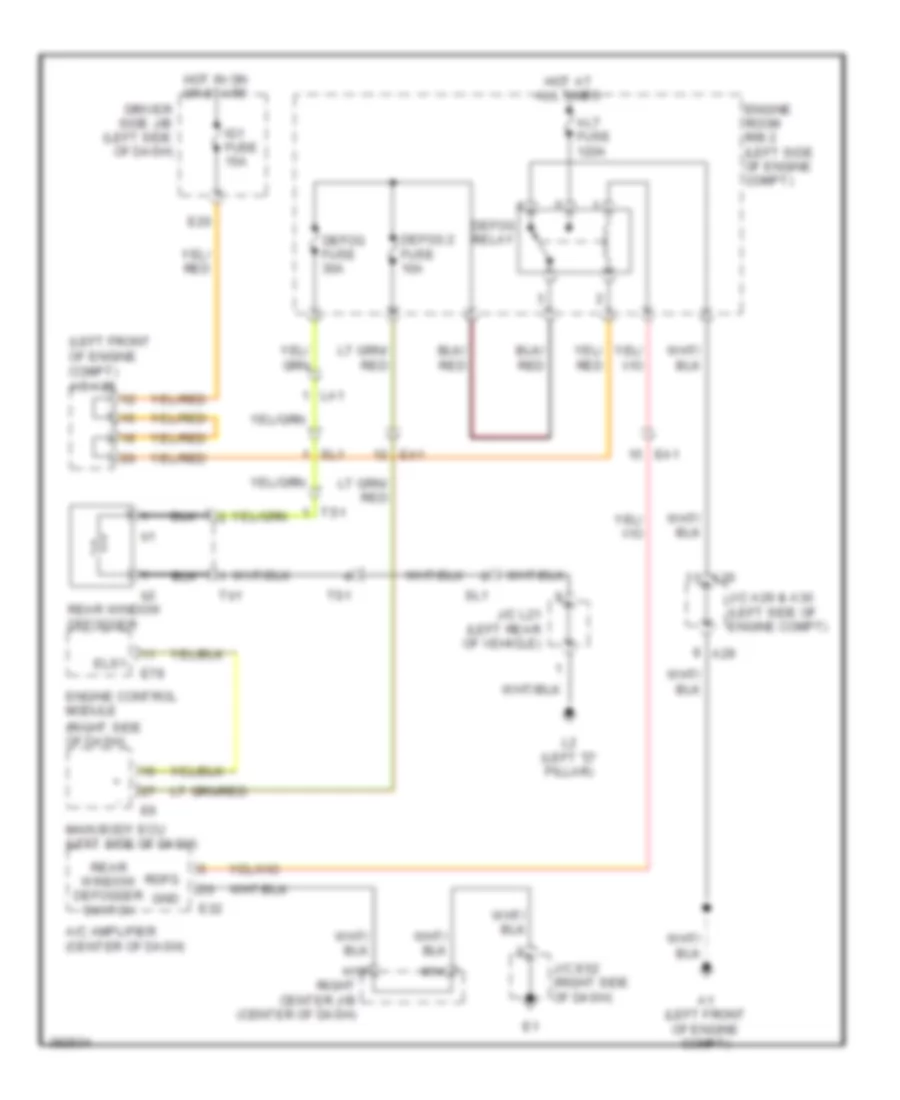
Defoggers Wiring Diagram for Toyota FJ Cruiser 2013
List of elements for Defoggers Wiring Diagram for Toyota FJ Cruiser 2013:
- (left front of engine compt) j/c a28
- (right side of dash)
- A/c amplifier (center of dash)
- A1 (left front of engine compt)
- A29
- A30
- Alt fuse 120a
- Defog 2 fuse 10a
- Defog fuse 30a
- Defog relay
- Driver side j/b (left side of dash)
- E20
- E32
- E78
- Ea1
- Els1
- Engine control module
- Engine room r/b 2 (left side of engine compt)
- Gnd
- H15
- Hot at all times
- Hot in on or start
- Ig1 fuse 15a
- J/c a29 & a30 (left side of engine compt)
- J/c e52 (right side of dash)
- J/c l21 (left rear of vehicle)
- L2 (left "d" pillar)
- La1
- M14
- Main body ecu (left side of dash)
- Rdfg
- Rear window defogger
- Rear window defogger switch
- Right center j/b (center of dash)
- Sl1
- Ts1
- Tb1
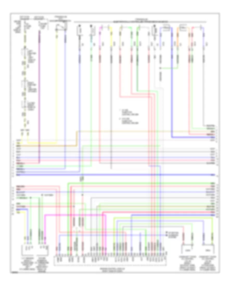
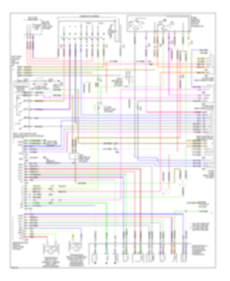
ENGINE PERFORMANCE
4.0L
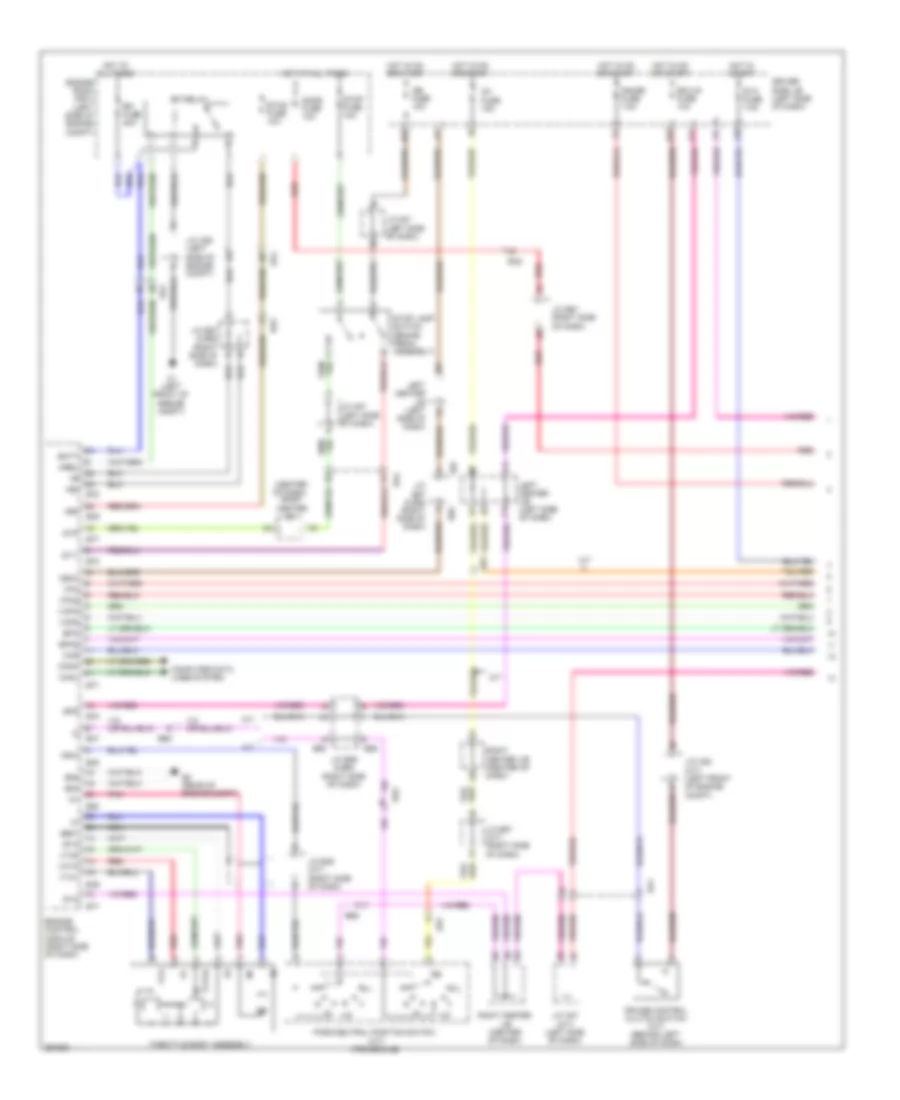
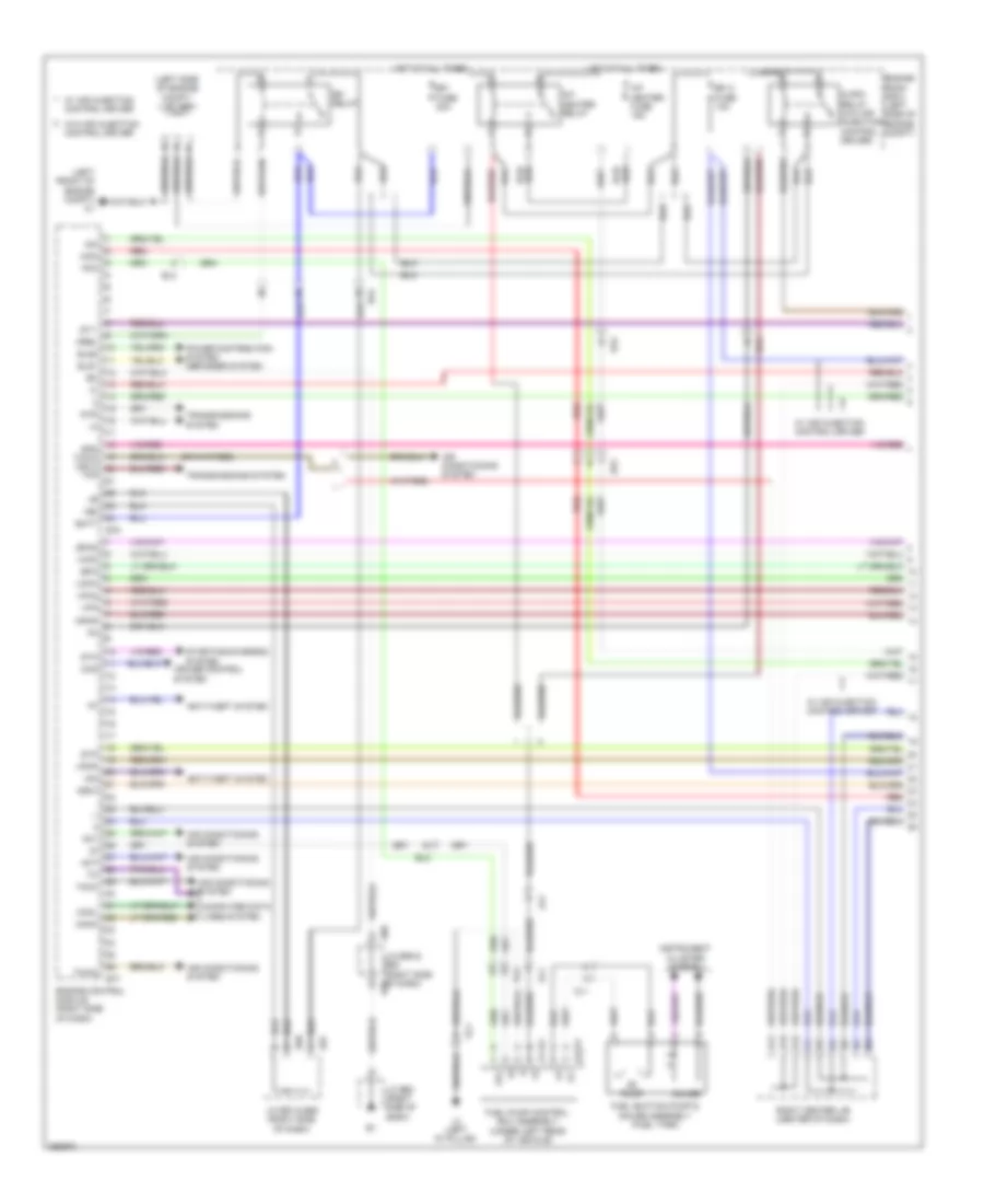
4.0L, Engine Performance Wiring Diagram (1 of 7) for Toyota FJ Cruiser 2013
List of elements for 4.0L, Engine Performance Wiring Diagram (1 of 7) for Toyota FJ Cruiser 2013:
- (left front of engine compt) a1
- (left side of engine compt) j/c a29
- +b2
- 4wd
- A/f heater fuse 15a
- A/f heater relay
- A11
- A12
- A13
- Ac1
- Act
- Aip
- Aip2
- Air conditioning system
- Anti-theft system
- Batt
- Be1
- C/opn relay (w/o air injection control driver)
- Canh
- Canl
- Ccs
- Computer data lines system
- Cruise control system
- E57
- E58
- E60
- E77
- E78
- Ea4
- Efi 2 fuse 10a
- Efi fuse 20a
- Efi relay
- El2
- Els1
- Els2
- Engine control module (right side of dash)
- Engine room r/b 2 (left side of engine compt)
- Epa
- Epa2
- Fp-
- Fpc
- Fuel pump control ecu assembly (under left rear of vehicle)
- Fuel suction pump & gauge assembly (fuel tank)
- Gauge
- Hot at all times
- Igsw
- Imi
- Imo
- Instrument cluster system
- J/c e52 (right side of dash)
- J/c e57 & e58 (right side of dash)
- J/c e59 & e60 (right side of dash) e59
- L2 (left "d" pillar)
- La1
- Mpmp
- Mrel
- Ol1
- Ol2
- Power distribution system defogger system
- Pump
- Red
- Right center j/b (center of dash)
- Spd thwo (or 3)
- St1-
- Sta
- Starting/charging system
- Stp
- Tach
- Tfn
- Thwo
- Transmissions system
- Vcp2
- Vcpa
- Vpa
- Vpa2
- Vpmp
- W/ air injection control driver
- W/o air injection control driver
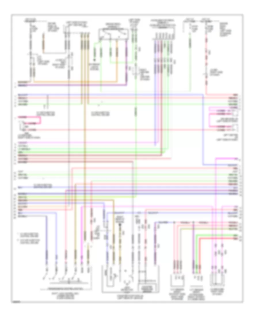
4.0L, Engine Performance Wiring Diagram (2 of 7) for Toyota FJ Cruiser 2013
List of elements for 4.0L, Engine Performance Wiring Diagram (2 of 7) for Toyota FJ Cruiser 2013:
- (accelerator pedal assembly) accelerator position sensor
- (brake pedal assembly) stop lamp switch
- (left side of dash) j/c a27
- (left side of dash) left center j/b
- (right rear of engine) b1
- Ab2
- Be2
- Be3
- Canister pressure sensor
- Canister pump module (left rear of vehicle)
- Dome fuse 10a
- Driver side j/b (left side of dash)
- E23
- E57
- E58
- E59
- E60
- Ea2
- Ea4
- El2
- Engine room r/b 2 (left side of engine compt)
- Epa
- Epa2
- Ex+
- Ex-
- Exterior
- Hot at all times
- Hot in on or start
- Ign fuse 10a
- J/c a27 (left side of dash)
- J/c e57 & e58 (right side of dash)
- J/c e59 & e60 (right side of dash)
- J/c e67 (right side of dash)
- J11
- K11
- L11
- La2
- Leak detection pump
- Left center j/b (left side of dash)
- Lights system
- Mt2
- Mt4
- Mtd
- Mtl
- Nssd
- Nssl
- Red
- Right center j/b (center of dash)
- Shift lock control ecu (under center floor console)
- Stop fuse 10a
- Transmission control switch
- Vc2
- Vcp2
- Vcpa
- Vent valve
- Vpa
- Vpa2
- Vvr+
- Vvr-
- Vvt sensor (bank1 exhaust side) (right side of engine)
- Vvt sensor (bank1 intake side) (front of right cylinder head)
- W/ air injection control driver
- W/o air injection control driver
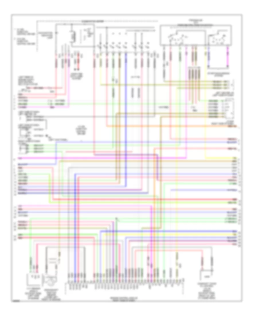
4.0L, Engine Performance Wiring Diagram (3 of 7) for Toyota FJ Cruiser 2013
List of elements for 4.0L, Engine Performance Wiring Diagram (3 of 7) for Toyota FJ Cruiser 2013:
- (left rear of engine compt) skid control ecu w/ actuator
- (left side of dash) j/c e50 & e51
- (left side of dash) left center j/b
- (right side of dash) j/c b46
- (transaxle) (a/t) park/neutral position switch
- 2-l
- 4-d
- A/t oil temp ind
- Airv
- B47
- Be1
- Be2
- Be3
- Camshaft timing oil control valve (bank 2 exhaust side) (front of left cylinder head)
- Combination meter
- Computer data lines system
- Control
- Crankshaft position sensor (lower left front of engine)
- D15
- E13
- E14
- E15
- E4 (left kick panel)
- E50
- E51
- Ea2
- Engine control module (right side of dash)
- Ev1+
- Ev1-
- Ev2+
- Ev2-
- Ex+
- Ex-
- Ex1b
- Ex2b
- J/c b45 (right side of dash)
- Left center j/b (left side of dash)
- Malfunction indicator lamp
- Ne+
- Ne-
- Oc2+
- Oc2-
- Oe2+
- Oe2-
- Ox1b
- Ox2b
- Pnk
- Red
- Sp1
- Starting/charging system
- Vcv1
- Vcv2
- Volt
- Vv1+
- Vv1-
- Vv2+
- Vv2-
- Vvt sensor (bank 2 exhaust side) (left side of engine)
- W/ air injection control driver
- W/o air injection control driver
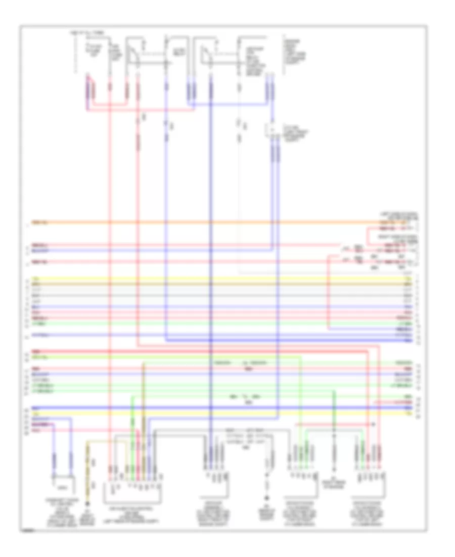
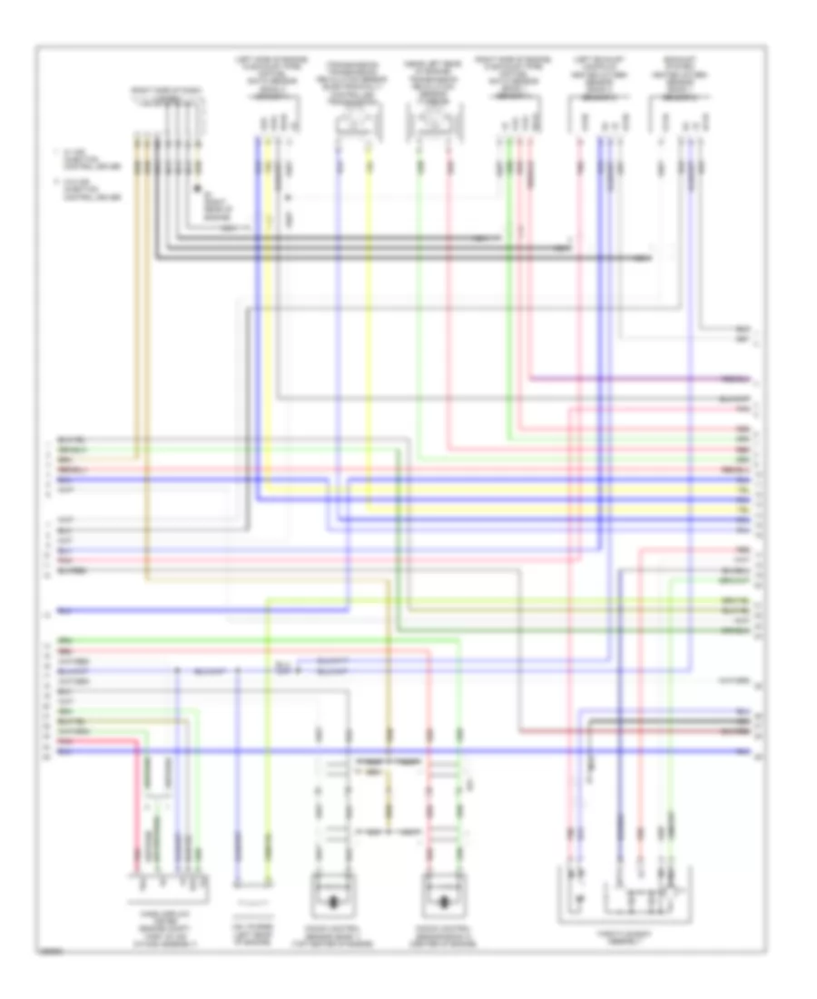
4.0L, Engine Performance Wiring Diagram (4 of 7) for Toyota FJ Cruiser 2013
List of elements for 4.0L, Engine Performance Wiring Diagram (4 of 7) for Toyota FJ Cruiser 2013:
- (left side of dash) driver side j/b
- (right side of dash) j/c e57 & e58
- +bl
- A/t
- A37
- A38
- Ab2
- Ai-vsv fuse 10a
- Ai-vsv relay
- Aip
- Aip2
- Air injection control driver (if equipped) (left rear of engine compt)
- Air pmp fuse 50a
- Air pump assembly (w/ air injection control driver) (right front of engine compt)
- Air pump htr relay (w/ air injection control driver)
- Air switching valve bank 1 (w/ air injection control driver) (top of right cylinder bank)
- Air switching valve bank 2 (w/ air injection control driver) (top of left cylinder bank)
- Aph+
- Aphg
- B1 (right rear of engine)
- B3 (rear of engine compt)
- Batt
- Be1
- Be2
- Be3
- Camshaft timing oil control valve (bank 2 intake side) (front of left cylinder head)
- E22
- E57
- E58
- Ea1
- Ea6
- Engine room r/b 2 (left side of engine compt)
- Gnd
- Gndl
- Hot at all times
- J/c a28 (left front of engine compt)
- M/t
- Pnk
- Red
- Sip
- Siv
- Vc2
4.0L, Engine Performance Wiring Diagram (5 of 7) for Toyota FJ Cruiser 2013
List of elements for 4.0L, Engine Performance Wiring Diagram (5 of 7) for Toyota FJ Cruiser 2013:
- (transaxle) (m/t) backup lamp switch
- (transaxle) electronically controlled transmission solenoid
- A/t
- Aidi
- Airp
- Alt
- B48
- Be1
- Camshaft timing oil control valve (bank 1 exhaust side) (front of right cylinder head)
- Camshaft timing oil control valve (bank 1 intake side) (front of right cylinder head)
- Driver side j/b (left side of dash)
- E2g
- Ee1
- Ekn2
- Eknk
- Engine control module (right side of dash)
- Etha
- Ethw
- Gauge fuse 7.5a
- Hot in on or start
- Ig1 fuse 15a
- Igt6
- J/c e57 (right side of dash)
- Knk1
- Knk2
- Left center j/b (left side of dash)
- M/t
- Nsw
- Oc1+
- Oc1-
- Oe1+
- Oe1-
- Ot+
- Ot-
- Ot2+
- Ot2-
- Pnk
- Power steering oil pressure switch (near right front of engine)
- Ppmp
- Psp
- Red
- Right center j/b (center of dash)
- Sl1+
- Sl1-
- Sl2+
- Sl2-
- Slt+
- Slt-
- Slu+
- Slu-
- Starting/ charging system
- Tha
- Vvl+
- Vvl-
- Vvt sensor (bank 2 intake side) (front of left cylinder head)
- W/ air injection control driver
- W/o air injection control driver
4.0L, Engine Performance Wiring Diagram (6 of 7) for Toyota FJ Cruiser 2013
List of elements for 4.0L, Engine Performance Wiring Diagram (6 of 7) for Toyota FJ Cruiser 2013:
- (exhaust system) heated oxygen sensor (bank 1 sensor 2)
- (left exhaust manifold) heated oxygen sensor (bank 2 sensor 2)
- (left side of engine, in exhaust pipe) air fuel ratio sensor (bank 2 sensor 1)
- (near left rear of engine) transmission revolution sensor (turbine)
- (right side of dash) j/c b46
- (right side of engine, in exhaust pipe) air fuel ratio sensor (bank 1 sensor 1)
- (transmission) transmission revolution sensor (electronically controlled transmission)
- A1a+
- A1a-
- A2a+
- A2a-
- B1 (right rear of engine)
- Bu1
- E2g
- Ha1a
- Ha2a
- Ht1b
- Ht2b
- Knock control sensor (bank 1) (top center of engine)
- Knock control sensor (bank 2) (center of engine)
- Mass airflow meter (engine compt, part of air intake assembly)
- Nca
- Ox1b
- Ox2b
- Pnk
- Red
- Tha
- Throttle body assembly
- Vsv (purge) (left rear of engine)
- Vta
- Vta2
- W/ air injection control driver
- W/o air injection control driver
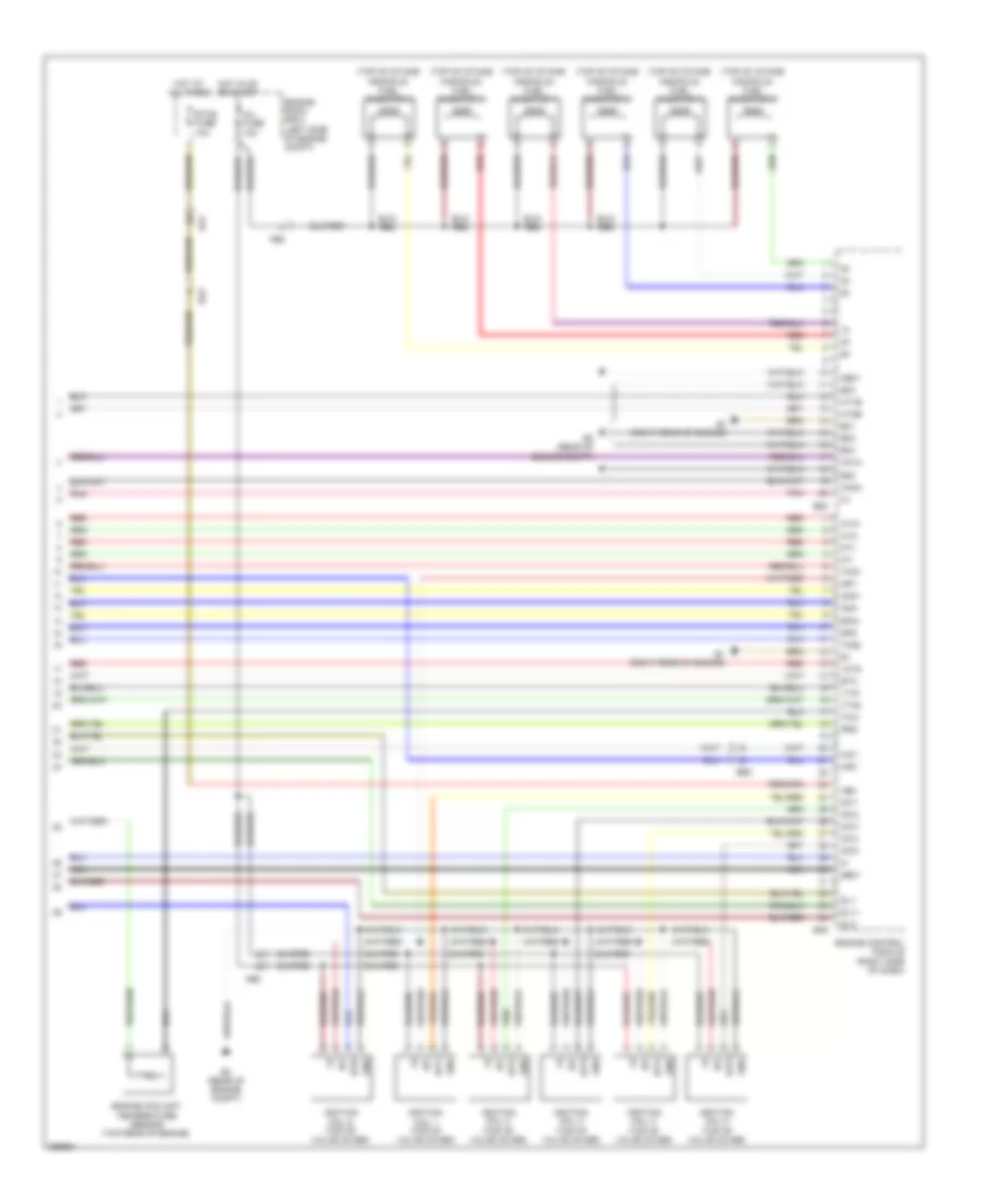
4.0L, Engine Performance Wiring Diagram (7 of 7) for Toyota FJ Cruiser 2013
List of elements for 4.0L, Engine Performance Wiring Diagram (7 of 7) for Toyota FJ Cruiser 2013:
- (top of intake manifold) fuel injector 1
- (top of intake manifold) fuel injector 2
- (top of intake manifold) fuel injector 3
- (top of intake manifold) fuel injector 4
- (top of intake manifold) fuel injector 5
- (top of intake manifold) fuel injector 6
- +bm
- A1a+
- A1a-
- A2a+
- A2a-
- Ab2
- Air1
- B1 (right rear of engine)
- B3 (rear of engine compt)
- B49
- B50
- Be3
- E01
- E02
- E03
- E04
- E05
- Ea4
- Engine control module (right side of dash)
- Engine coolant temperature sensor (top rear of engine)
- Engine room r/b 2 (left side of engine compt)
- Eta
- Etcs fuse 10a
- Ge01
- Gnd
- Ha1a
- Ha2a
- Hai1
- Hot at all times
- Hot in on or start
- Ht1b
- Ht2b
- Igf
- Igf1
- Ignition coil 1 (top of valve cover)
- Ignition coil 2 (top of valve cover)
- Ignition coil 3 (top of valve cover)
- Ignition coil 4 (top of valve cover)
- Ignition coil 5 (top of valve cover)
- Ignition coil 6 (top of valve cover)
- Igt1
- Igt2
- Igt3
- Igt4
- Igt5
- Igt6
- Inj fuse 10a
- Me01
- Nca
- Nt+
- Nt-
- Pnk
- Prg
- Red
- Sl1+
- Sl1-
- Sl2-
- Sp2+
- Sp2-
- Tho1
- Tho2
- Thw
- Vcta
- Vta1
- Vta2
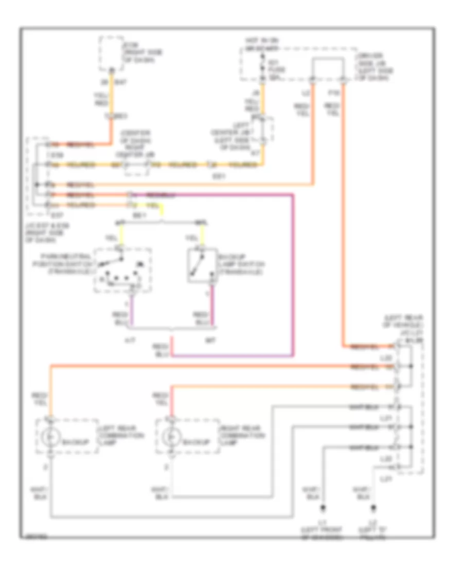
EXTERIOR LIGHTS
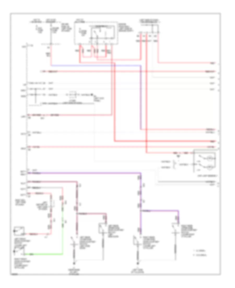
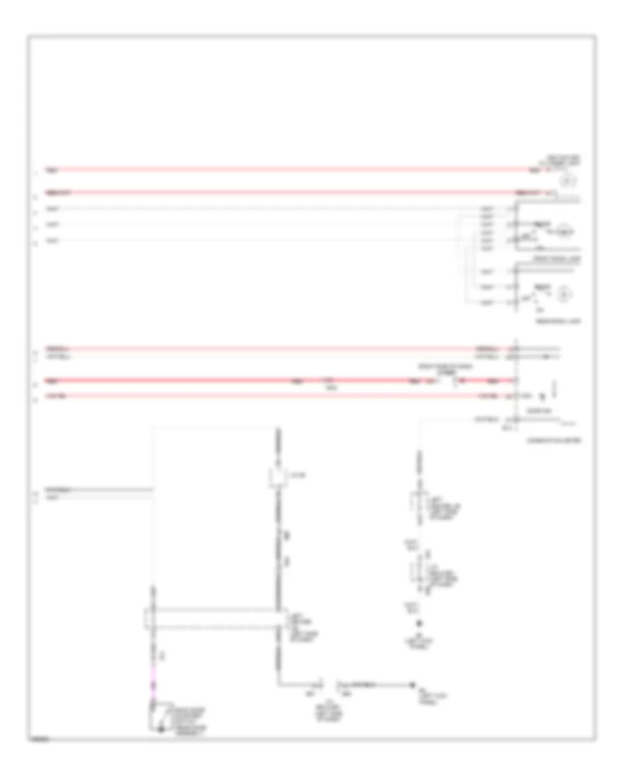
Backup Lamps Wiring Diagram for Toyota FJ Cruiser 2013
List of elements for Backup Lamps Wiring Diagram for Toyota FJ Cruiser 2013:
- (center of dash) right center j/b
- (left rear of vehicle) j/c l21 & l22
- 2-l
- 4-d
- A/t
- B47
- Backup
- Backup lamp switch (transaxle)
- Be1
- Be3
- Driver side j/b (left side of dash)
- E57
- E58
- Ecm (right side of dash)
- Ee1
- F10
- Hot in on
- Ig1 fuse 15a
- J/c e57 & e58 (right side of dash)
- L1 (left front of chassis)
- L2 (left "d" pillar)
- L21
- L22
- Left center j/b (left side of dash)
- Left rear combination lamp
- M/t
- Or start
- Park/neutral position switch (transaxle)
- Right rear combination lamp
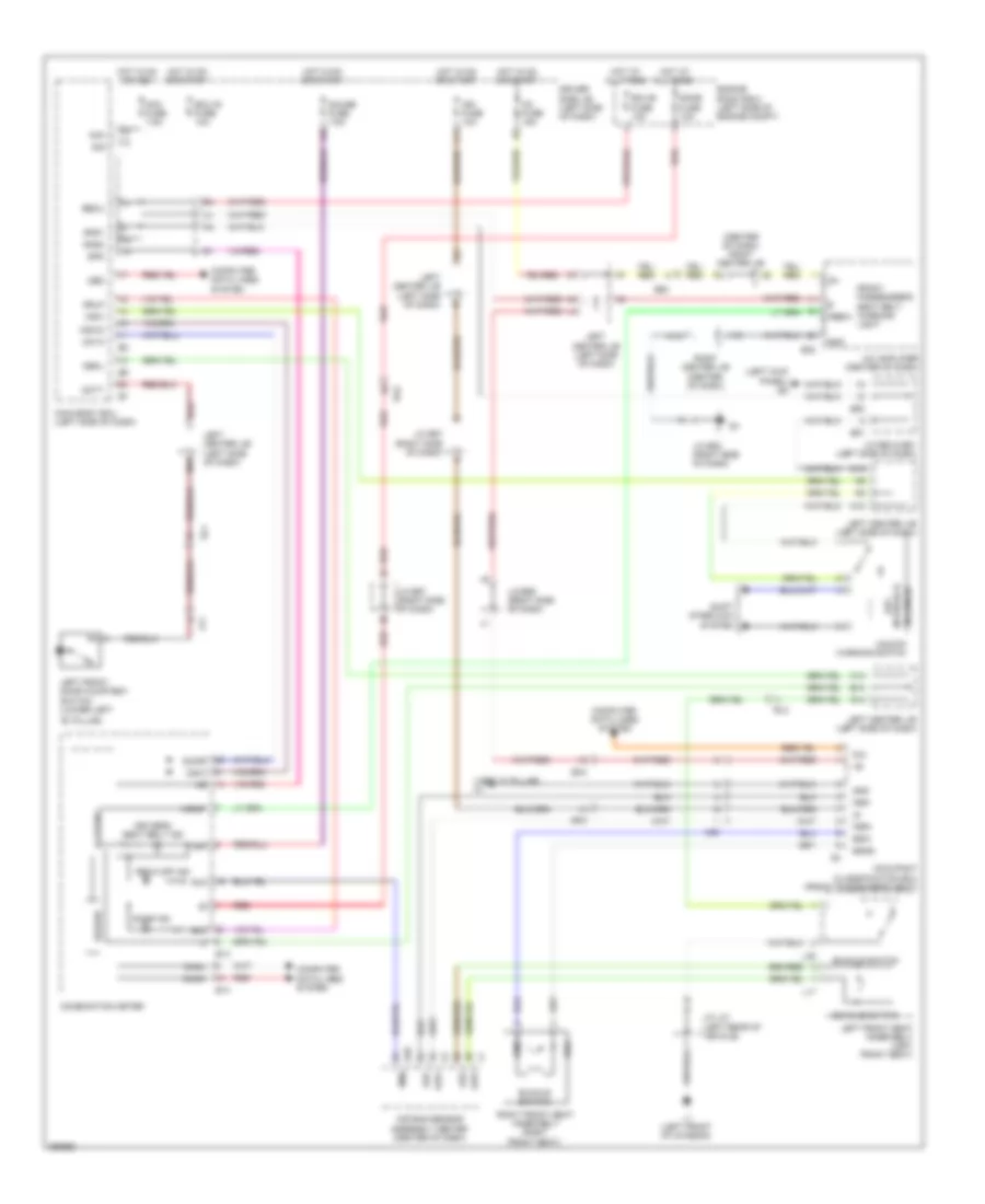
Exterior Lamps Wiring Diagram (1 of 2) for Toyota FJ Cruiser 2013
List of elements for Exterior Lamps Wiring Diagram (1 of 2) for Toyota FJ Cruiser 2013:
- (left side of dash) j/c e50 & e51
- A/c amplifier (center of dash)
- Acc
- Acc fuse 7.5a
- B11
- Center stop lamp
- Combination meter
- D15
- Dcty
- Driver side j/b (left side of dash)
- E13
- E15
- E18
- E20
- E24
- E32
- E4 (left kick panel)
- E50
- E51
- Ecu-ig fuse 10a
- F13
- F15
- F16
- Gnd
- Gnd1
- Gnd2
- H15
- Haz
- Hazard switch
- Head
- Headlamp dimmer switch assembly
- Hot in on or acc
- Hot in on or start
- Ig1 fuse 15a
- Interior lights system
- J/c e50 (left side of dash)
- J/c e52 (right side of dash)
- J/c l20 (lower left rear of vehicle)
- J/c l21 & l22 (left rear of vehicle)
- J14
- J15
- J23
- L1 (left front of chassis)
- L11
- L12
- L14
- L15
- L2 (left "d" pillar)
- L21
- L22
- Left
- Left center j/b (left side of dash)
- Left rear combination lamp
- Left turn ind
- License plate lamp
- Light control switch
- M14
- M15
- N14
- Off
- Pcty
- Pnk
- Right
- Right center j/b (center of dash)
- Right rear combination lamp
- Right turn ind
- Rlcy
- Rrcy
- Sig
- Sl1
- Stop
- Tail
- Tail fuse 10a
- Tail relay
- Trly main body ecu
- Ts1
- Turn
- Turn signal flasher (left side of dash)
- Turn switch
Exterior Lamps Wiring Diagram (2 of 2) for Toyota FJ Cruiser 2013
List of elements for Exterior Lamps Wiring Diagram (2 of 2) for Toyota FJ Cruiser 2013:
- (left side of dash)
- A1 (left front of engine compt)
- A2 (left front of engine compt)
- E4 (left kick panel)
- E5 (right kick panel)
- E77
- Ea4
- Ee1
- Engine control module (right side of dash)
- Engine room r/b 2 (left side of engine compt)
- F10
- G10
- Ge1
- Ge2
- He1
- He2
- Hot at all times
- J/b fuse 50a
- J/c a27
- J/c a28 (left front of engine compt)
- J/c e50 (left side of dash)
- J/c g1 (right "c" pillar)
- J/c h1 (near left front door)
- K10
- Left center j/b (left side of dash)
- Left front turn signal & parking lamp
- Left outer rear view mirror
- M10
- Parking
- Pnk
- Right center j/b (center of dash)
- Right front turn signal & parking lamp
- Right outer rear view mirror
- Skid control ecu w/ actuator (left rear of engine compt)
- Stop fuse 10a
- Stop lamp switch (brake pedal assembly)
- Stop lp ctrl relay
- Stp
- Stp2
- Stpo
- Trn-haz fuse 15a
- Turn
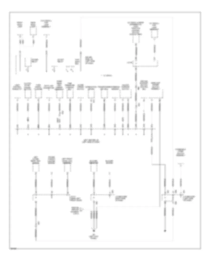
GROUND DISTRIBUTION
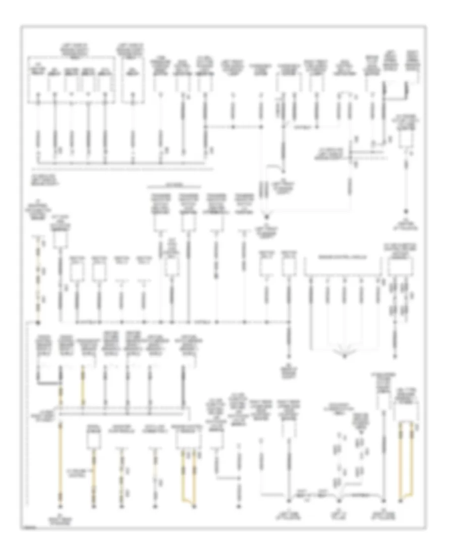
Ground Distribution Wiring Diagram (1 of 3) for Toyota FJ Cruiser 2013
List of elements for Ground Distribution Wiring Diagram (1 of 3) for Toyota FJ Cruiser 2013:
- (4wd)
- (a/t 4wd)
- (a/t 4wd) 4wd control ecu
- (a/t 4wd) add actuator assembly
- (if
- (if equipped) power outlet socket (120v)
- (jbl type)
- (left side of engine compt) engine room r/b 2
- (left side of engine compt) engine room r/b 4
- (m/t 4wd)
- (w/ air injection control driver) air pump assembly
- (w/ air injection control driver) air switching valve (bank 1)
- (w/ air injection control driver) air switching valve (bank 2)
- (w/ drl) daytime running light resistor
- (w/ power outlet (120v)) voltage inverter
- A/f heater relay
- A1 (left front of engine compt)
- A2 (left front of engine compt)
- A29
- A30
- A37
- Ab2
- Air fuel ratio sensor (bank 1 sensor 1) shield
- Air fuel ratio sensor (bank 2 sensor 1) shield
- B1 (right rear of engine)
- B3 (rear of engine compt)
- B49
- B50
- Bd1
- Be1
- Be2
- Brake fluid level warning switch
- Canada
- Canister pump module
- Control
- Crankshaft position sensor shield
- Data link connector 3
- Defog relay
- Drl relay
- Ea6
- Efi relay
- Ek4
- El2
- Engine control module
- Equipped) air injection control driver
- From e5 ground (diagram 2 0f 3)
- Heated oxygen sensor (bank 1 sensor 2) shield
- Heated oxygen sensor (bank 2 sensor 2) shield
- Heater relay
- I1 (left side of tailgate)
- Ignition coil 1
- Ignition coil 2
- Ignition coil 3
- Ignition coil 4
- Ignition coil 5
- Ignition coil 6
- Ik1
- J/c a29 & a30 (left side of engine compt)
- J/c b46 (right side of dash)
- K1 (left "c" pillar)
- K10
- K2 (right side of tailgate)
- K3 (center of tailgate)
- Knock control sensor (bank 1) shield
- Knock control sensor (bank 2) shield
- Kq1
- Left front speed sensor shield
- Left front turn signal & parking lamp
- Nca
- Occupant classification ecu
- Right front speed sensor shield
- Right front turn signal & parking lamp
- Right rear lower side door courtesy switch
- Right rear upper side door courtesy switch
- Skid control ecu w/ actuator
- Speaker assembly 1 w/ box
- Spiral cable
- Sta relay
- Tire pressure warning reset switch
- Transfer indicator switch (4wd position)
- Transfer indicator switch (center differential)
- Transfer indicator switch (l4 position)
- Transfer indicator switch (neutral position)
- W/ cruise
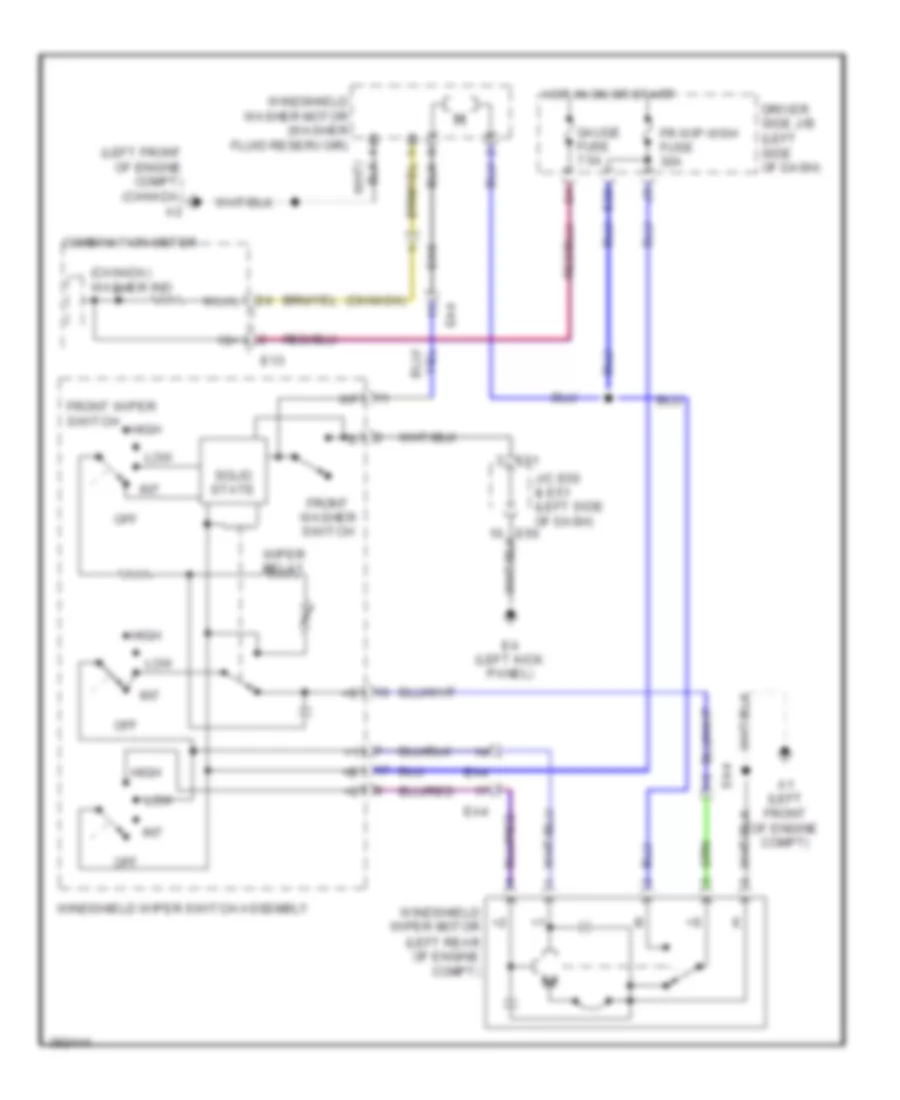
- Windshield washer motor
- Windshield wiper motor
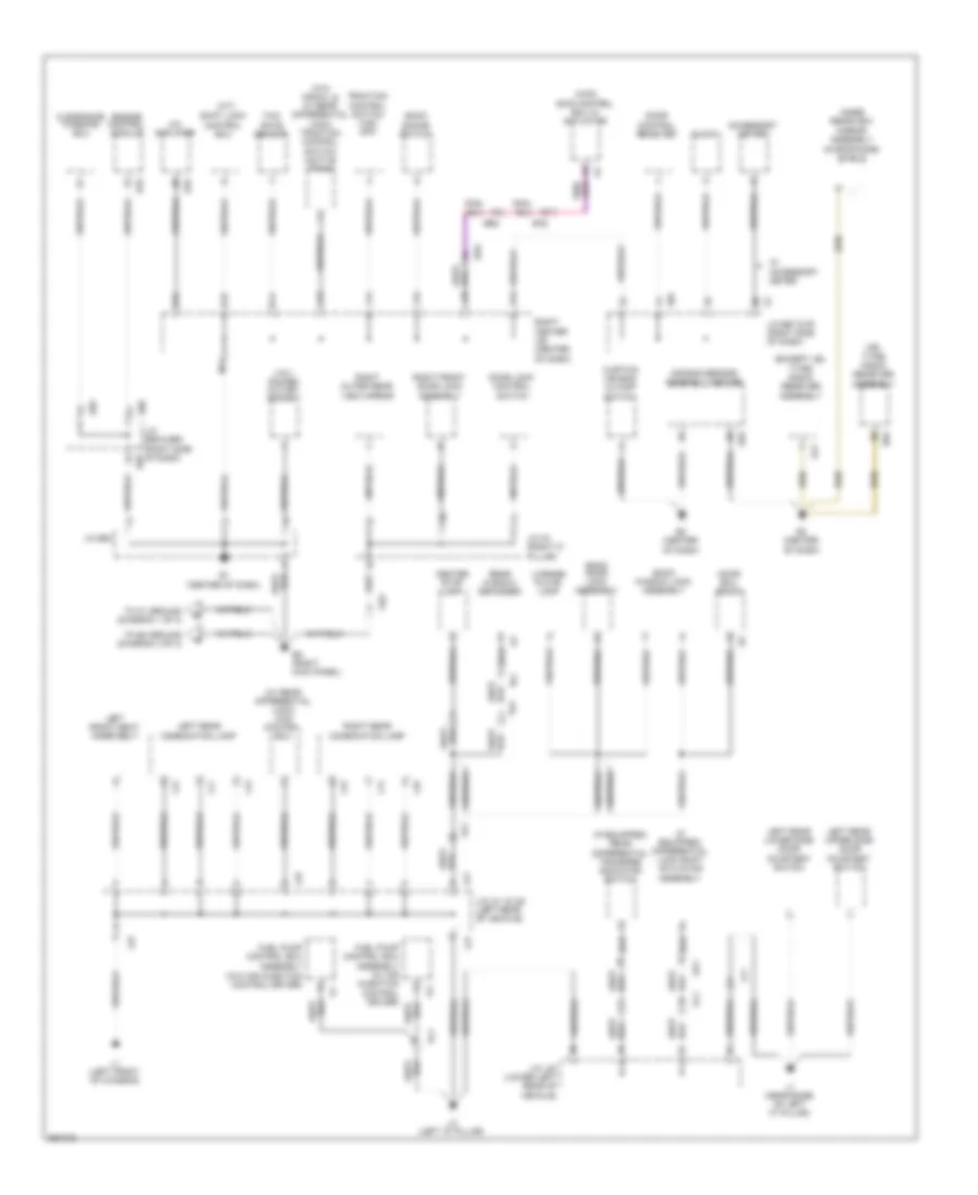
Ground Distribution Wiring Diagram (2 of 3) for Toyota FJ Cruiser 2013
List of elements for Ground Distribution Wiring Diagram (2 of 3) for Toyota FJ Cruiser 2013:
- (12v) power outlet socket
- (4wd) skid control ecu w/ actuator
- (a/t)
- (except jbl type) radio receiver assembly
- (if equipped) differential lock shift actuator assembly
- (if equipped) rear differential transfer indicator switch
- (jbl type) radio receiver assembly
- (microphone) shield
- (w/ rear differential lock) 4wd control ecu
- (w/o crawl & w/ rear differential lock) traction control switch (active trac)
- A/c amplifier
- Accessory meter
- Air bag sensor assembly center
- B14
- B15
- Back door lock assembly
- Back sonar switch
- Back window lock assembly
- Be2
- Center stop lamp
- Clearance warning ecu
- Clock
- Curtain air bag cutoff switch
- D15
- Door control receiver
- Door ecu (back)
- Door lock control switch
- E1 (center of dash)
- E2 (center of dash)
- E29
- E3 (center of dash)
- E32
- E41
- E5 (right kick panel)
- E59
- E60
- E67
- E78
- E83
- Ea2
- Engine control module
- Fuel pump control ecu assembly (w/o air injection control driver)
- Ge2
- H15
- Inner rearview mirror assembly
- J/c e52
- J/c e59 & e60 (right side of dash) e59
- J/c e67 & f5 (right side of dash)
- J/c g1 (right "c" pillar)
- J/c l20 (lower left rear of vehicle)
- J/c l21 & l22 (left rear of vehicle)
- J1 (near base of left "c" pillar)
- Jl1
- L1 (left front of chassis)
- L11
- L12
- L13
- L14
- L15
- L16
- L2 (left "d" pillar)
- L21
- L22
- Left front seat inner belt
- Left rear combination lamp
- Left rear lower side door courtesy switch
- Left rear upper side door courtesy switch
- License plate lamp
- M14
- Od1
- Ol1
- Rear window defogger
- Right center j/b (center of dash)
- Right front door lock assembly
- Right outer rear view mirror
- Right rear combination lamp
- Shift lock control ecu
- Sl1
- To e4 ground (diagram 3 of 3)
- To k1 ground (diagram 1 of 3)
- Traction control switch (vsc off)
- Ts1
- Tb1
- W/ accessory meter
- Yaw rate sensor
Ground Distribution Wiring Diagram (3 of 3) for Toyota FJ Cruiser 2013
List of elements for Ground Distribution Wiring Diagram (3 of 3) for Toyota FJ Cruiser 2013:
- (a/t)
- (m/t)
- (w/ crawl & rear differential lock) traction control switch (active trac)
- (w/ crawl) map lamp assembly
- (w/o crawl) map lamp assembly
- A13
- A15
- B14
- B15
- Blower resistor
- Blower switch
- Clutch start cancel switch
- Combination meter
- D15
- Data link connector
- Dc skt relay
- Driver side j/b (left side of dash)
- Driving support switch control ecu
- E13
- E15
- E4 (left kick panel)
- E50
- E51
- E55
- E56
- From e5 ground (diagram 2 of 3)
- Front room lamp
- G15
- H15
- He2
- Headlamp dimmer switch assembly
- Inner rear view mirror assembly
- J/c e50 & e51 (left side of dash)
- J/c e55 & e56 (right side of dash)
- J/c h1 (near left front door)
- J/c m5
- J15
- K15
- L15
- Left center j/b (left side of dash)
- Left front door lock assembly
- Left outer rear view mirror
- Light control rheostat
- M14
- M15
- Main body ecu
- N12
- N13
- N14
- N15
- Outer mirror switch
- Power relay
- Power window master switch
- Re2
- Re4
- Rear room lamp
- Rm1
- Steering sensor
- Tire pressure warning ecu
- Transponder key ecu
- Turn signal flasher
- Unlock warning switch
- W/ crawl
- Windshield wiper switch assembly
HEADLIGHTS
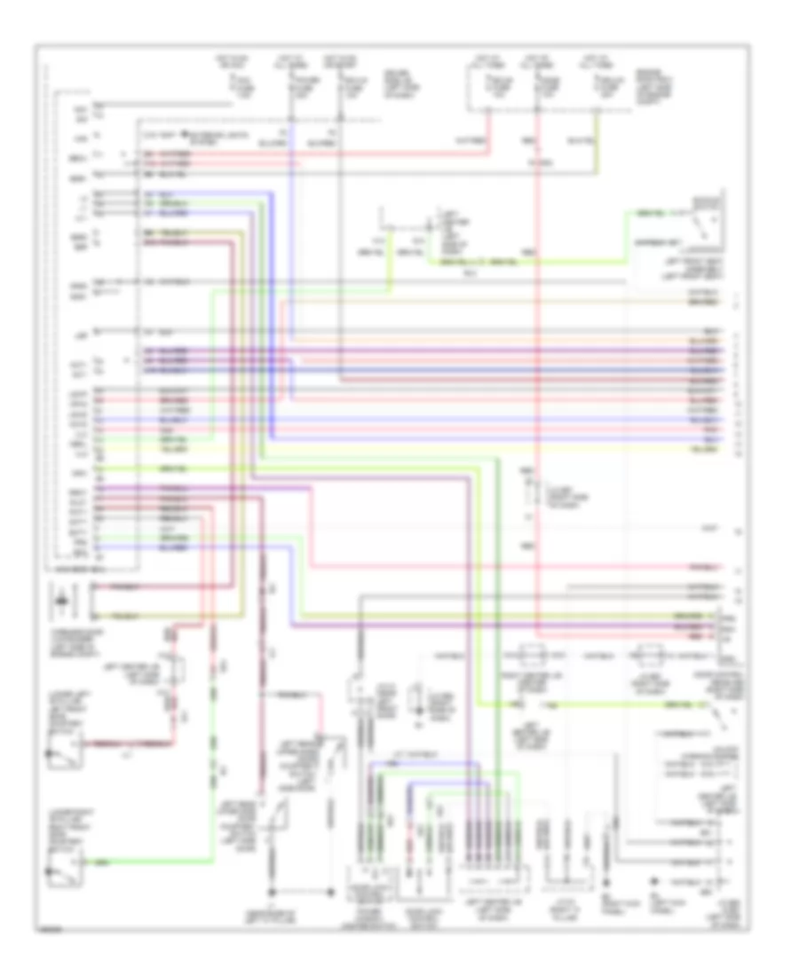
Headlights Wiring Diagram (1 of 2) for Toyota FJ Cruiser 2013
List of elements for Headlights Wiring Diagram (1 of 2) for Toyota FJ Cruiser 2013:
- Acc
- Acc fuse 7.5a
- Bcty
- Beam ind
- Becu
- Body ecu (left side of dash)
- Ca2
- Combination meter
- D15
- Dcty
- Dim
- Driver side j/b (left side of dash)
- Drl fuse 7.5a
- E13
- E15
- E4 (left kick panel)
- E50
- E51
- Ea1
- Ecu-b fuse 10a
- Ecu-ig fuse 10a
- Engine room r/b 2 (left side of engine compartment)
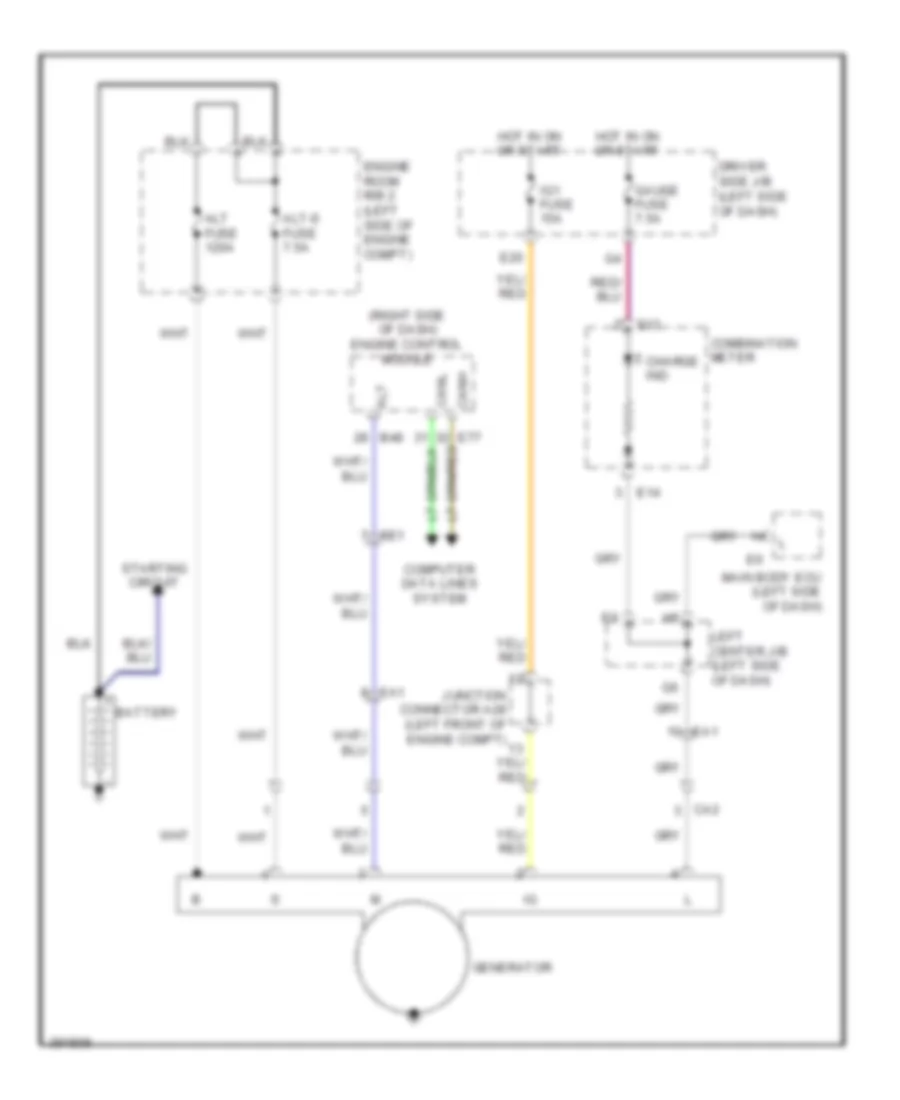
- Generator
- Gnd1
- Gnd2
- H-on
- Head
- Head relay
- Hf2
- Hind
- Hon2
- Hot at all times
- Hot in on or acc
- Hot in on or start
- Hrly
- Interior lights system
- J/c e50 & e51 (left side of dash)
- J17
- J20
- Left center j/b (left side of dash)
- Left headlamp
- Left high head fuse 10a
- Left low head fuse 10a
- Parking brake switch (parking brake assembly)
- Pcty
- Pkb
- Red
- Right headlamp
- Right high head fuse 10a
- Right low head fuse 10a
- Rlcy
- Rrcy
- Sig
- Usa
Headlights Wiring Diagram (2 of 2) for Toyota FJ Cruiser 2013
List of elements for Headlights Wiring Diagram (2 of 2) for Toyota FJ Cruiser 2013:
- (behind left side of front bumper) daytime running light resistor
- (left front of engine compartment) a1
- A29
- A30
- Dim relay
- Dimmer switch
- Drl
- Drl relay
- E4 (left kick panel)
- Engine room r/b 4 (left side of engine compartment)
- Flash
- Head
- Headlamp dimmer switch assembly
- High
- J/c a29 & a30 (left side of engine compartment)
- Light control switch
- Low
- Low high
- Red
- Tail off
- Usa
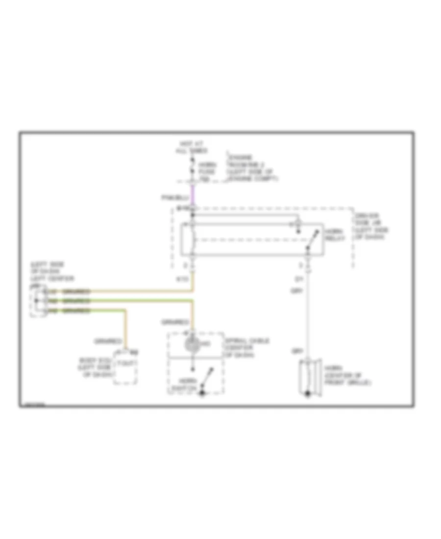
HORN
Horn Wiring Diagram for Toyota FJ Cruiser 2013
List of elements for Horn Wiring Diagram for Toyota FJ Cruiser 2013:
- (left side of dash) left center j/b
- Body ecu (left side of dash)
- Driver side j/b (left side of dash)
- E10
- Engine room r/b 2 (left side of engine compt)
- Horn (center of front grille)
- Horn fuse 10a
- Horn relay
- Horn switch
- Hot at all times
- K13
- Spiral cable (center of dash)
- Tout
INSTRUMENT CLUSTER
Instrument Cluster Wiring Diagram (1 of 2) for Toyota FJ Cruiser 2013
List of elements for Instrument Cluster Wiring Diagram (1 of 2) for Toyota FJ Cruiser 2013:
- (a/t) (m/t)
- (canada)
- (left kick panel) e4
- (left side of dash) j/c e50 & e51
- (left side of dash) left center j/b
- (lower front of engine)
- 4wd ind center differential lock ind
- A-trac ind
- A/t
- A/t oil temp ind
- A/t p
- A1 (left front of engine compt)
- A10
- A11
- A12
- A13
- A14
- A15
- A16
- A17
- A18
- A19
- A20
- A21
- A22
- A23
- A24
- A25
- A26
- A27
- A28
- A29
- A30
- A31
- A32
- Abs ind
- Acc fuse 7.5a
- Auto lsd ind
- B10
- B11
- B12
- B13
- B14
- B15
- B16
- B17
- B18
- B19
- B20
- B21
- B22
- B23
- B24
- Be2
- Beam ind
- Brake fluid level warning switch (brake fluid reservoir)
- Brake ind
- C11
- Canh
- Canl
- Charge ind
- Combination meter
- Computer data lines system
- Crawl ind
- Cruise ind
- D11
- D15
- Dome fuse 10a
- Door ind
- Driver side j/b (left side of dash)
- Driver's seat belt ind
- E12
- E13
- E14
- E15
- E50
- E51
- Ea2
- Ee1
- Engine controls system
- Engine oil pressure switch
- Engine room r/b 2 (left side of engine compt)
- Exterior lights system
- Flashing
- Fuel control
- Fuel warning ind
- Gauge fuse 7.5a
- Headlights system
- Hot at all times
- Hot in on or acc
- Hot in on or start
- Ig1 fuse 15a
- Illumination
- Interior lights system
- J/c a29 & a30 (left side of engine compt)
- J12
- J20
- Lbl
- Left center j/b (left side of dash)
- Left turn ind
- M/t
- Maint reqd ind
- Malfunction ind lamp
- Odo/trip
- Oil pressure ind
- Parking brake switch (parking brake assembly)
- Pkb
- Pnk
- Rear differential lock ind
- Red
- Right center j/b (center of dash)
- Right turn ind
- Rsca off ind
- Skid control ecu w/ actuator (left rear of engine compt)
- Slip ind
- Sp1
- Srs ind
- Starting/charging system
- Tire pressure ind
- Tpms control
- Trac off ind
- Transmissions system
- Volt control
- Vsc off ind
- W/ crawl w/o crawl
- Warning systems
- Washer ind
- Wiper/washer system
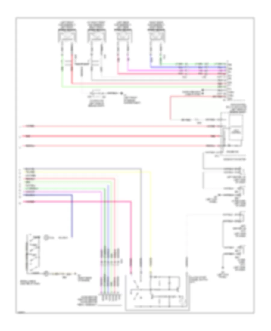
Instrument Cluster Wiring Diagram (2 of 2) for Toyota FJ Cruiser 2013
List of elements for Instrument Cluster Wiring Diagram (2 of 2) for Toyota FJ Cruiser 2013:
- (left side of dash) body ecu
- (lower right "b" pillar)
- (rear door assembly)
- 4wd control ecu (rear differential lock) (left side of dash)
- A/c amplifier (center of dash)
- Acc
- Accessory meter
- Bcty
- Clock
- Computer data lines system
- Control driver
- D15
- Data link connector 3 (lower left side of dash)
- Dcty
- Dcy2
- Dmin
- Door courtesy switch (back door)
- Door courtesy switch (left rear lower side) (left side door)
- Door courtesy switch (left rear upper side) (left side door)
- Door courtesy switch (right rear lower side) (lower left "c" pillar)
- Door courtesy switch (right rear upper side) (lower right "c" pillar)
- Driver side j/b (left side of dash)
- Drlp
- E33
- E43
- E59
- E60
- E67
- E77
- E78
- Ek2
- Ek3
- Ek4
- El1
- El2
- Engine control module (right side of dash)
- Except jbl type
- Fuel suction pump & gauge assembly (fuel tank)
- Gauge
- H12
- I1 (left side of tailgate)
- Ig+
- Ik1
- Ill+
- Ill-
- Ind
- Interior lights system
- J/c e52 (right side of dash)
- J/c e59 & e60 (right side of dash)
- J/c e67 & f5 (right side of dash)
- J1 (near base of left "c" pillar)
- J11
- Jbl type
- Jl1
- K10
- K11
- Kswo
- L11
- Left center j/b (left side of dash)
- Left front door courtesy switch (lower left "b" pillar)
- M11
- M12
- M14
- Mpx2
- Pcty
- Radio receiver assembly
- Red
- Right center j/b (center of dash)
- Right front door courtesy switch
- Rlcy
- Rrcy
- Spd
- Speaker assembly w/ box 1
- Tac
- Tach
- Taco
- Tamo
- Thwo
- Tire pressure warning ecu (upper right side of dash)
- Voltage inverter (right side of luggage area)
- W/ air injection
- W/o air injection
INTERIOR LIGHTS
Courtesy Lamps Wiring Diagram (1 of 2) for Toyota FJ Cruiser 2013
List of elements for Courtesy Lamps Wiring Diagram (1 of 2) for Toyota FJ Cruiser 2013:
- (left side of dash) driver side j/b
- A13
- Acc
- Acc fuse 7.5a
- Bcty
- Body ecu (left side of dash)
- Dcty
- Dcy2
- Dome fuse 10a
- Dome relay
- Driver side j/b (left side of dash)
- Drlp
- E4 (left kick panel)
- Ea1
- Ek4
- El1
- Engine room r/b 2 (left side of engine compt)
- Gauge fuse 7.5a
- Gnd1
- Gnd2
- H12
- Hot at all times
- Hot in on or acc
- Hot in on or start
- I1 (left side of tailgate)
- Ik1
- Ile
- J/c e50 (left side of dash)
- J1 (near base of left "c" pillar)
- J22
- Jl1
- Left center j/b (left side of dash)
- Left front door courtesy switch (lower left "b" pillar)
- Left rear lower side door courtesy switch (left side door)
- Left rear upper side door courtesy switch (left side door)
- Lmry
- Map lamp assembly
- Pcty
- Red
- Right front door courtesy switch (lower right "b" pillar)
- Right rear lower side door courtesy switch (lower left "c" pillar)
- Right rear upper side door courtesy switch (lower right "c" pillar)
- Rlcy
- Rm1
- Rrcy
- W/ crawl
- W/o crawl
Courtesy Lamps Wiring Diagram (2 of 2) for Toyota FJ Cruiser 2013
List of elements for Courtesy Lamps Wiring Diagram (2 of 2) for Toyota FJ Cruiser 2013:
- (right side of dash) j/c e67
- Back door courtesy switch (rear door assembly)
- Combination meter
- D15
- Door
- Door ind
- E13
- E15
- E4 (left kick panel)
- E50
- E51
- Ea2
- El1
- Front room lamp
- Ignition key cylinder light
- J/c e50 & e51 (left side of dash)
- J/c e50 & e51 (left side of dash) e50
- J/c m5
- L15
- Left center j/b (left side of dash)
- Off
- Re4
- Rear room lamp
- Red
- Rm1
Instrument Illumination Wiring Diagram (1 of 2) for Toyota FJ Cruiser 2013
List of elements for Instrument Illumination Wiring Diagram (1 of 2) for Toyota FJ Cruiser 2013:
- 100w
- A11
- A15
- Acc
- Acc fuse 7.5a
- Becu
- Body ecu (left side of dash)
- Combination meter
- D15
- Driver side j/b (left side of dash)
- E10
- E13
- E14
- E4 (left kick panel)
- E50
- E51
- Ecu-b fuse 10a
- Ecu-ig fuse 10a
- Ee1
- Ek2
- Engine room r/b 2 (left side of engine compt)
- G10
- G13
- Gnd
- Gnd1
- Gnd2
- H10
- He1
- Head
- Headlamp dimmer switch assembly
- Hot at all times
- Hot in on or acc
- Hot in on or start
- Ig1 fuse 15a
- Ill+
- Ill-
- Illumination
- J/b fuse 50a
- J/c e50 & e51 (left side of dash)
- J13
- K10
- K3 (center of tailgate)
- L10
- Left center j/b (left side of dash)
- Light control rheostat
- Light control switch
- M10
- Main switch
- N10
- Off
- Re4
- Right center j/b (center of dash)
- Rly
- Rm1
- Sig
- Spiral cable (center of dash)
- Steering pad switch ind
- Tail
- Tail fuse 10a
- Tail relay
- Trly
- Voltage inverter (right side of luggage area) k7
Instrument Illumination Wiring Diagram (2 of 2) for Toyota FJ Cruiser 2013
List of elements for Instrument Illumination Wiring Diagram (2 of 2) for Toyota FJ Cruiser 2013:
- A/c amplifier (center of dash)
- A/t shift lever illumination
- Accessory meter
- Back sonar switch
- Clock
- Crawl control switch assembly (w/ crawl)
- Curtain airbag cutoff switch (behind left side of dash)
- D15
- Differential lock switch (w/ crawl)
- Differential lock switch (w/o crawl)
- E10
- E3 (center of dash)
- E32
- E4 (left kick panel)
- E41
- E42
- E43
- E5 (right kick panel)
- E67
- E83
- Except jbl type
- F10
- G10
- Ge2
- Gnd
- H10
- He2
- Ill+
- Ill-
- J/c e50 (left side of dash)
- J/c e52 (right side of dash)
- J/c e67 & f5 (right side of dash)
- J/c g1 (right "c" pillar)
- J/c h1 (near left front door)
- J/c m5
- Jbl type
- L10
- L11
- Left outer rear view mirror
- M10
- M14
- N10
- Radio receiver assembly
- Right center j/b (center of dash)
- Right outer rear view mirror
- Swg
- Traction control switch (active trac) (w/ crawl)
- Traction control switch (active trac) (w/o crawl)
- Traction control switch (vsc off)
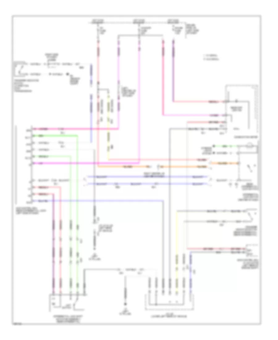
NAVIGATION
Parking Assistant Wiring Diagram for Toyota FJ Cruiser 2013
List of elements for Parking Assistant Wiring Diagram for Toyota FJ Cruiser 2013:
- (center of dash) clearance warning buzzer
- (left side of dash) left center j/b
- 2-l
- 4-d
- A/t
- Back sonar switch
- Backup lamp switch (transaxle)
- Bbz
- Be1
- Bor
- Clearance warning ecu (right side of dash)
- Combination meter
- Driver side j/b (left side of dash)
- E13
- E59
- E60
- Ee1
- El2
- Hot in on or start
- Ig 1 fuse 15a
- Interior lights system
- J/c e52 (right side of dash)
- J/c e57 (right side of dash)
- J/c e59 & e60 (right side of dash)
- J/c e59 (right side of dash)
- J11
- K11
- L11
- L15
- Left rear ultrasonic sensor (left rear of vehicle)
- M/t
- M14
- Park/neutral position switch (transaxle)
- Red
- Right center j/b (center of dash)
- Right rear ultrasonic sensor (right rear of vehicle)
- Sor
- Spd
- Dl1
Rear View Camera Wiring Diagram for Toyota FJ Cruiser 2013
List of elements for Rear View Camera Wiring Diagram for Toyota FJ Cruiser 2013:
- 2-l
- 4-d
- A/t
- Acc
- Back door courtesy switch (w/ parking assist) (rear door assembly)
- Backup lamp switch (w/ parking assist) (transaxle)
- Bcty
- Be1
- Cb+
- Cgnd
- Cv+
- Cv-
- D15
- Driver side j/b (left side of dash)
- E4 (left kick panel)
- E50
- E51
- E59
- Ecu-b fuse 10a
- El1
- Engine room r/b 2 (left side of engine compt)
- H15
- Hot at all times
- Hot in on or start
- Ig1 fuse 15a
- Inner rear view mirror assembly
- J/c e50 & e51 (left side of dash)
- J/c e57 (right side of dash)
- J/c e59 & e60 (right side of dash) e60
- Left center j/b (left side of dash)
- M/t
- Mi1
- Mic
- Nca
- Park/neutral position switch (w/ parking assist) (transaxle)
- Re2
- Rear television camera assembly (w/ parking assist)
- Red
- Rev
- Right center j/b (center of dash)
- Sl1
- Sound systems
- Sc1
- W/ garage door opener
POWER DISTRIBUTION
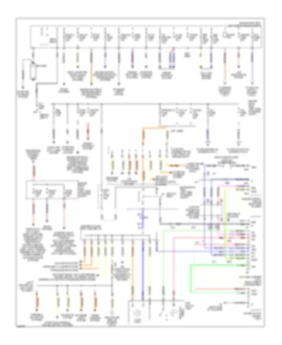
Power Distribution Wiring Diagram (1 of 2) for Toyota FJ Cruiser 2013
List of elements for Power Distribution Wiring Diagram (1 of 2) for Toyota FJ Cruiser 2013:
- (center of dash) right center j/b
- (center of tailgate) k3
- (not used)
- (right side of dash) junction connector b46
- 400w inv fuse 80a
- 400w inv relay
- A/f heater fuse 15a
- A/t
- Abs mtr fuse 40a
- Abs sol fuse 30a
- Ac1
- Ac2
- Acc1
- Acc2
- Ai-vsu fuse 10a
- Air conditioning system
- Air conditioning, anti-lock brakes, cruise control, exterior lights, mirrors, navigation & transmissions systems
- Air pmp fuse 50a
- Alt fuse 120a
- Alt-s fuse 7.5a
- Am1 fuse 50a
- Am2 fuse 30a
- Anti-lock brakes & exterior lights systems
- Anti-lock brakes system
- Aux lp fuse 15a
- B47
- B48
- Battery
- Be2
- Be3
- Body computer, door locks & anti-theft systems
- Clt
- Computer data lines system
- Cruise control, engine controls & transmissions systems
- Defog relay
- Defogger system
- Dome fuse 10a
- Dr/lck fuse 20a
- E59
- E60
- E78
- Ea4
- Ecu-b fuse 10a
- Ee1
- Efi fuse 20a
- Ek2
- Els2
- Engine control module (right side of dash)
- Engine controls system
- Engine controls, exterior lights, transmissions, cruise control, shift interlock & anti-lock brakes systems
- Engine controls, transmissions & cruise control systems
- Engine room r/b 2 (left side of engine compt)
- Engine room r/b 3 (left side of engine compt)
- Etcs fuse 10a
- Excd
- Exterior lights system
- F13
- From driver side j/b (diagram 2 of 2)
- From engine room r/b 2 (diagram 1 of 2)
- G13
- Gnd
- Head relay
- Heater fuse 60a
- Horn fuse 10a
- Horns & anti-theft systems
- Ill+
- Ill-
- Illum (100w)
- Ind
- Indicator (400w)
- Instrument cluster system
- Interior lights, engine controls, warning, anti-lock brakes, cruise control, instrument cluster, door locks, transmissions & anti-theft systems
- J/b fuse 50a
- J13
- Junction connector a28 (left front of engine compt)
- Junction connector e59 & e60 (right side of dash)
- K2 (right side of tailgate)
- Kp1
- Left center j/b (left side of dash)
- M/t
- Main switch (120v)
- Mirrors & navigation systems
- Navigation system
- Nsw
- Obd fuse 7.5a
- Offroad lp fuse 15a
- Pa1
- Power outlet socket (120v)
- Radio 1 fuse 20a
- Radio 2 fuse 20a
- Red
- Rly
- Short pin
- Sound systems
- Spd
- Starting/ charging system
- Starting/charging & cruise control systems
- Stop fuse 10a
- To driver side j/b (diagram 2 of 2)
- To engine room r/b 2 (diagram 1 of 2)
- To ignition switch (diagram 2 of 2)
- Towing fuse 15a
- Towing tail fuse 15a
- Trans- missions system
- Transmissions system
- Trn-haz fuse 15a
- Voltage inverter (120v) (right side of luggage area)
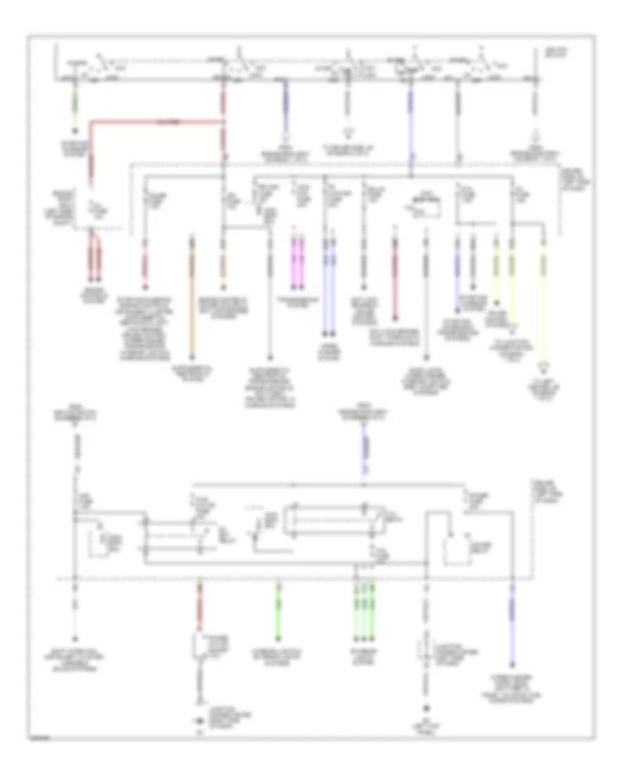
Power Distribution Wiring Diagram (2 of 2) for Toyota FJ Cruiser 2013
List of elements for Power Distribution Wiring Diagram (2 of 2) for Toyota FJ Cruiser 2013:
- 4wd/ diff fuse 20a
- Acc
- Acc fuse 7.5a
- Am1
- Am2
- Anti-lock brakes & cruise control systems
- Anti-lock brakes, shift interlock & warning systems
- B11
- Cruise control system
- Dc skt relay
- Door locks, wiper/washer, interior lights & body computer systems
- Driver side j/b (left side of dash)
- E12
- E20
- E21
- E22
- E23
- E4 (left kick panel)
- Ecu-ig fuse 10a
- Engine controls system
- Engine controls, cruise control & anti-lock brakes systems
- Engine room r/b 2 (diagram 1 of 2)
- Engine room r/b 2 (left side of engine compt)
- Exterior lights system
- F11
- F13
- Fr wip-wsh fuse 30a
- From
- From engine room r/b 2 (diagram 1 of 2)
- From ignition switch (diagram 2 of 2)
- Gauge fuse 7.5a
- Ig1
- Ig1 fuse 15a
- Ig2
- Ign fuse 10a
- Ignition switch
- Inj fuse 10a
- Interior lights & exterior lights systems
- J10
- J11
- J28
- J30
- Junction connector e50 (left side of dash)
- Junction connector e52 (right side of dash)
- L15
- L20
- Lock
- Main body ecu
- Off on
- On off
- Power fuse 30a
- Power outlet socket (12v)
- Power relay
- Pwr outlet fuse 15a
- Rr wsh fuse 15a
- Shift interlock, instrument cluster, mirrors & sound systems
- Sig
- St1
- St2
- Sta fuse 7.5a
- Start
- Starting/ charging & transmissions systems
- Starting/ charging system
- Tail fuse 10a
- Tail relay
- To driver side j/b (diagram 2 of 2)
- To junction connector a28 (diagram 1 of 2)
- To left center j/b (diagram 1 of 2)
- Transmissions system
- Trly
- Wig
- Wiper/ washer system
- Wiper/washer, door locks, anti-theft & trunk, tailgate, fuel doors systems
POWER DOOR LOCKS
Power Door Locks Wiring Diagram (1 of 2) for Toyota FJ Cruiser 2013
List of elements for Power Door Locks Wiring Diagram (1 of 2) for Toyota FJ Cruiser 2013:
- (lower left "b" pillar) left front door courtesy switch
- (lower right "b" pillar) right front door courtesy switch
- (right side of dash)
- Acc
- Acc fuse 7.5a
- Act+
- Act-
- Actd
- B10
- Bcty
- Bdr1
- Becu
- Buckle switch
- Bzr
- Bzr2
- D15
- Dbkl
- Dcty
- Dome fuse 10a
- Door control receiver (right side of dash)
- Door lock control switch
- Dr/lck fuse 20a
- Driver side j/b (left side of dash)
- E4 (left kick panel)
- E5 (right kick panel)
- E50
- E51
- Ea2
- Ecu-b fuse 10a
- Ecu-ig fuse 10a
- Ek4
- El1
- El2
- Engine room r/b 2 (left side of engine compt)
- Exterior lights system
- F11
- F12
- G11
- G14
- Ge1
- Ge2
- Gnd
- Gnd1
- Gnd2
- H11
- H12
- H14
- Haz
- He1
- He2
- Hot at all times
- Hot in on or acc
- Hot in on or start
- Ik1
- J/c e50 & e51 (left side of dash)
- J/c e52 (right side of dash)
- J/c e67
- J/c e67 (right side of dash)
- J/c g1 (right "c" pillar)
- J/c h1 (near left front door)
- J1 (near base of left "c" pillar)
- J14
- Jl1
- Ksw
- L18
- Left center j/b (left side of dash)
- Left front seat inner belt (left front seat)
- Left rear lower side door courtesy switch (left side door)
- Left rear upper side door courtesy switch (left side door)
- Lsr
- Lswd
- Lswp
- M12
- M14
- Main body ecu
- Mpx2
- N12
- Pcty
- Pnk
- Power fuse 30a
- Power window master switch
- Prg
- Rda
- Red
- Right center j/b (center of dash)
- Rlcy
- Rrcy
- Sig
- Ul1
- Ul2
- Ul3
- Unlock warning switch
- Wireless door lock buzzer (left side of engine compt)
Power Door Locks Wiring Diagram (2 of 2) for Toyota FJ Cruiser 2013
List of elements for Power Door Locks Wiring Diagram (2 of 2) for Toyota FJ Cruiser 2013:
- (rear floor pan) j/c l22
- Act+
- Act-
- Back door ecu (lower left of back door)
- Back door lock assembly (right "d" pillar)
- Back door lock cylinder assembly (right "d" pillar)
- Back window lock assembly (right "d" pillar)
- Bdr
- Becu
- Courtesy switch
- Door courtesy switch (back door) (rear door assembly)
- Ek4
- El1
- Gcty
- Ge1
- Ge2
- Ghc+
- Gnd
- He1
- He2
- Housing position switch
- I1 (left side of tailgate)
- Ik1
- Key
- Key lock
- L1 (left front of chassis)
- L2 (left "d" pillar)
- Left center j/b (left side of dash)
- Left front door lock assembly (left front door)
- Lock
- Mpx2
- Pnk
- Rear wiper motor assembly (w/ rear wiper) (rear tailgate assembly)
- Red
- Reverse position switch
- Right front door lock assembly (right front door)
- Right rear lower side door courtesy switch (lower left "c" pillar)
- Right rear upper side door courtesy switch (lower right "c" pillar)
- Sgnd
- Sig
- Sl1
- Unlock
- Unlock detection
- W/ rear wiper
- W/o rear wiper
- Wip+
- Wip-
POWER MIRRORS
Electrochromic Mirror Wiring Diagram for Toyota FJ Cruiser 2013
List of elements for Electrochromic Mirror Wiring Diagram for Toyota FJ Cruiser 2013:
- 2-l
- 4-d
- A/t
- Acc
- Back door courtesy switch (w/ parking assist) (rear door assembly)
- Backup lamp switch (w/ parking assist) (transaxle)
- Bcty
- Be1
- Cb+
- Cgnd
- Cv+
- Cv-
- D15
- Driver side j/b (left side of dash)
- E4 (left kick panel)
- E50
- E51
- E59
- Ecu-b fuse 10a
- El1
- Engine room r/b 2 (left side of engine compt)
- H15
- Hot at all times
- Hot in on or start
- Ig1 fuse 15a
- Inner rear view mirror assembly
- J/c e50 & e51 (left side of dash)
- J/c e57 (right side of dash)
- J/c e59 & e60 (right side of dash) e60
- Left center j/b (left side of dash)
- M/t
- Mi1
- Mic
- Nca
- Park/neutral position switch (w/ parking assist) (transaxle)
- Re2
- Rear television camera assembly (w/ parking assist)
- Red
- Rev
- Right center j/b (center of dash)
- Sl1
- Sound systems
- Sc1
- W/ garage door opener
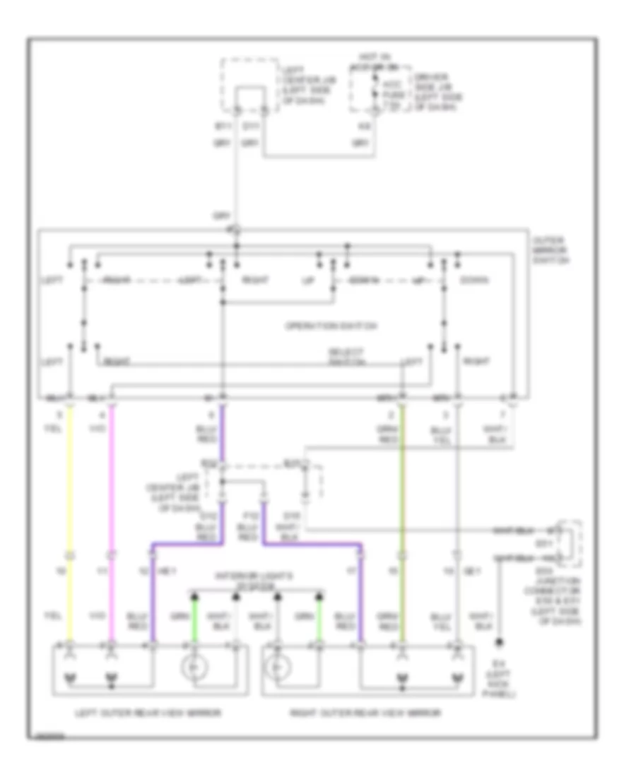
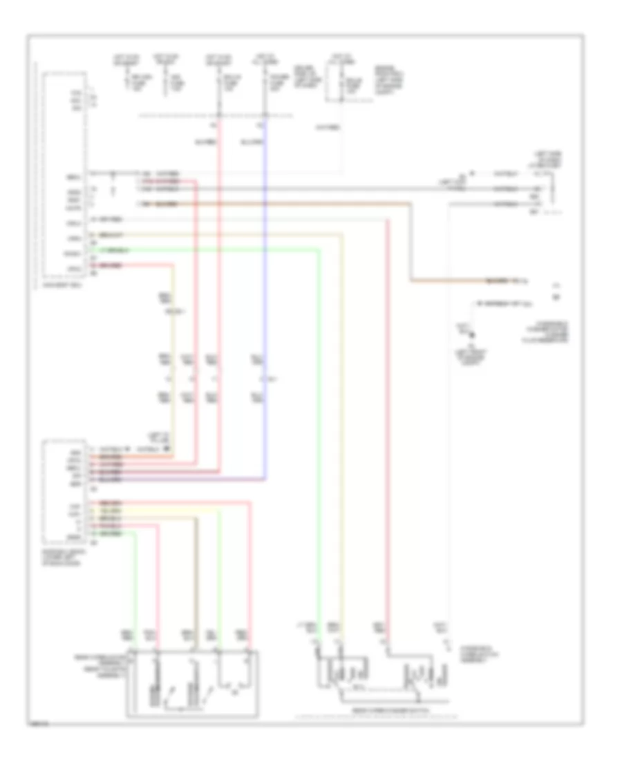
Power Mirrors Wiring Diagram for Toyota FJ Cruiser 2013
List of elements for Power Mirrors Wiring Diagram for Toyota FJ Cruiser 2013:
- Acc fuse 7.5a
- B11
- B12
- B15
- D11
- D12
- D15
- Down
- Driver side j/b (left side of dash)
- E4 (left kick panel)
- E50
- E51
- F12
- Ge1
- He1
- Hot in acc or on
- Interior lights system
- Junction connector e50 & e51 (left side of dash)
- Left
- Left center j/b (left side of dash)
- Left outer rear view mirror
- Mlh
- Mlv
- Mrh
- Mrv
- Operation switch
- Outer mirror switch
- Right
- Right outer rear view mirror
- Select switch
POWER WINDOWS
Power Windows Wiring Diagram for Toyota FJ Cruiser 2013
List of elements for Power Windows Wiring Diagram for Toyota FJ Cruiser 2013:
- (near left front door) j/c h1
- Acc
- Acc fuse 7.5a
- Becu
- Dcty
- Door locks system
- Driver side j/b (left side of dash)
- E4 (left kick panel)
- Ecu-b fuse 10a
- Ecu-ig fuse 10a
- El1
- Engine room r/b 2 (left side of engine compt)
- Ge2
- Gnd1
- Gnd2
- H12
- He2
- Hot at all times
- Hot in on or acc
- Hot in on or start
- J/c e50 (left side of dash)
- Jl1
- Left center j/b (left side of dash)
- Left front door courtesy switch (lower left "b" pillar)
- Left front power window regulator motor (left front door)
- M12
- Main body ecu
- Power fuse 30a
- Power relay
- Power window master switch
- Pws
- Red
- Right front power window regulator motor (right front door)
- Right front power window switch
- Sig
- Ul1
RADIO
Radio Wiring Diagram, with JBL (1 of 2) for Toyota FJ Cruiser 2013
List of elements for Radio Wiring Diagram, with JBL (1 of 2) for Toyota FJ Cruiser 2013:
- Acc
- Acc fuse 7.5a
- Agnd
- Ali
- Antenna
- Ari
- Asgn
- Atx+
- Atx-
- Au1
- Au2
- Auxi
- C11
- D11
- Driver side j/b (left side of dash)
- E3 (center of dash)
- E43
- E83
- E85
- Ea4
- Eau
- Ee1
- Ek3
- Engine room r/b 2 (left side of engine compt)
- F12
- G12
- Gnd
- Hook
- Hot at all times
- Hot in run or acc
- Ill+
- Ill-
- Inner rear view mirror assembly
- Interior lights system
- Ivo+
- Ivo-
- Left center j/b (left side of dash)
- Left side steering pad switch
- Macc
- Mi1+
- Mic-
- Microphone
- Min+
- Mode
- Mute
- N12
- Nca
- Off
- Pnk
- Radio 1 fuse 20a
- Radio receiver assembly
- Re2
- Red
- Right center j/b (center of dash)
- Right side steering pad switch
- Seek+
- Seek-
- Sgnd
- Sld
- Sld1
- Sns2
- Spd
- Spiral cable (center of dash)
- Sw1
- Sw2
- Swg
- Voice
- Vol+
- Vol-
Radio Wiring Diagram, with JBL (2 of 2) for Toyota FJ Cruiser 2013
List of elements for Radio Wiring Diagram, with JBL (2 of 2) for Toyota FJ Cruiser 2013:
- +b2
- Acc
- Cdl+
- Cdl-
- Cdr+
- Cdr-
- Combination meter
- Csld
- Driver side j/b (left side of dash)
- E13
- E59
- E60
- E68
- E82
- E84
- E88
- Ea4
- Ee2
- Ek3
- Ek4
- El1
- Engine room r/b 2 (left side of engine compt)
- Fl+
- Fl-
- Fr+
- Fr-
- Ge2
- Gnd
- Gnd2
- He2
- Hot at all times
- Int+
- Int-
- J/c e59 & e60 (right side of dash) e59
- J/c e68 & f6 (right side of dash)
- J11
- K10
- K11
- K2 (right side of tailgate)
- L11
- Left center j/b (left side of dash)
- Left front speaker
- Left front tweeter
- Left rear tweeter
- Multi-media interface ecu (center of dash)
- Mut1
- Mute
- Nca
- Pnk
- Radio 2 fuse 20a
- Radio receiver assembly
- Red
- Right front speaker
- Right front tweeter
- Right rear tweeter
- Rl+
- Rl-
- Rr+
- Rr-
- Sld
- Sld2
- Spd
- Speaker assembly w/ box 1
- Stereo jack adapter assembly 1
- Tx+
- Tx-
- Tx1+
- Tx1-
- Txm+
- Txm-
- Ulo+
- Ulo-
- Uro+
- Uro-
- Usd1
Radio Wiring Diagram, without JBL (1 of 2) for Toyota FJ Cruiser 2013
List of elements for Radio Wiring Diagram, without JBL (1 of 2) for Toyota FJ Cruiser 2013:
- Acc
- Acc fuse 7.5a
- Au1
- Au2
- C11
- D11
- Driver side j/b (left side of dash)
- E3 (center of dash)
- E41
- E42
- E68
- E85
- Ea4
- Eau
- Ee1
- Engine room r/b 2 (left side of engine compt)
- F12
- Fl+
- Fl-
- Fr+
- Fr-
- Ge2
- Gnd
- He2
- Hook
- Hot at all times
- Hot in on or acc
- Ill+
- Ill-
- Inner rear view mirror assembly
- Interior lights system
- J/c e68 & f6 (right side of dash)
- Left center j/b (left side of dash)
- Left front speaker
- Left front tweeter
- Left side steering pad switch
- Macc
- Mi1+
- Mic-
- Microphone
- Min+
- Min-
- Mode
- N12
- Nca
- Off
- Pnk
- Radio 1 fuse 20a
- Radio receiver assembly
- Re2
- Red
- Right center j/b (center of dash)
- Right front speaker
- Right front tweeter
- Right side steering pad switch
- Rl+
- Rl-
- Rr+
- Rr-
- Seek+
- Seek-
- Sgnd
- Sns2
- Spiral cable (center of dash)
- Voice
- Vol+
- Vol-
Radio Wiring Diagram, without JBL (2 of 2) for Toyota FJ Cruiser 2013
List of elements for Radio Wiring Diagram, without JBL (2 of 2) for Toyota FJ Cruiser 2013:
- Acc
- Agnd
- Ali
- Ari
- Asgn
- Auxi
- Cdl+
- Cdl-
- Cdr+
- Cdr-
- Combination meter
- Csld
- Driver side j/b (left side of dash)
- E13
- E43
- E53
- E54
- E82
- E84
- E88
- Ee2
- Gnd
- J/c e53 & e54 (right side of dash)
- J/c e59 (right side of dash)
- J11
- K11
- L11
- Left center j/b (left side of dash)
- Left roof speaker
- Multi-media interface ecu (if equipped) (center of dash)
- Mut1
- Mute
- Nca
- Pnk
- Radio receiver assembly
- Re2
- Red
- Right roof speaker
- Spd
- Speaker condenser (left side of dash)
- Stereo jack adapter assembly 1
- Sw1
- Sw2
- Swg
- Tx1+
- Tx1-
- Txm+
- Txm-
- Ulo+
- Ulo-
- Uro+
- Uro-
- Usd1
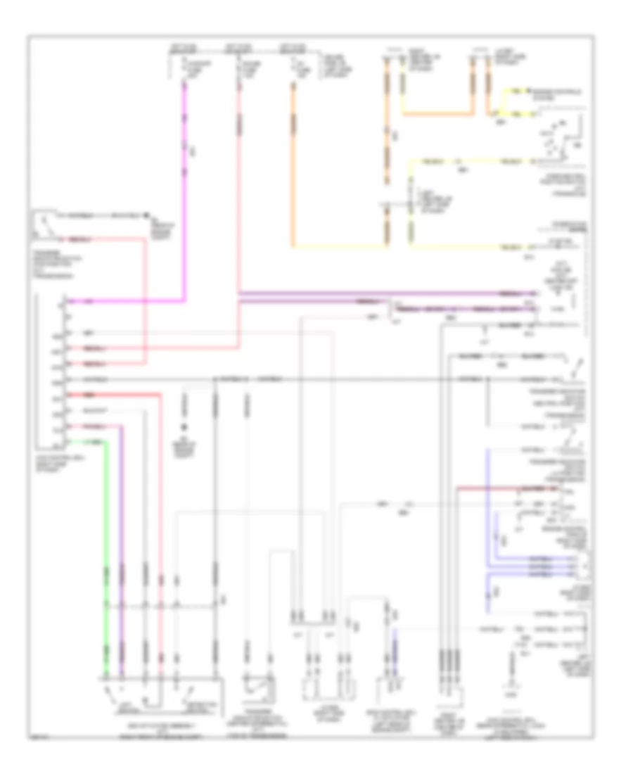
SHIFT INTERLOCK
Shift Interlock Wiring Diagram for Toyota FJ Cruiser 2013
List of elements for Shift Interlock Wiring Diagram for Toyota FJ Cruiser 2013:
- (right side of dash) j/c e52
- Acc
- Acc fuse 7.5a
- B12
- B15
- B47
- Be1
- Be3
- C11
- Canh
- Canl
- Computer data lines system
- D11
- D15
- Driver side j/b (left side of dash)
- E4 (left kick panel)
- E50
- E51
- E77
- Ea4
- Ecu-ig fuse 10a
- Ee1
- Engine control module (right side of dash)
- Engine room r/b 3 (left side of engine compt)
- Hot at all times
- Hot in on or acc
- Hot in on or start
- Ig1 fuse 15a
- J/c a27 (left side of dash)
- J/c e50 & e51 (left side of dash)
- J12
- J28
- Key interlock solenoid
- Key switch
- Kls+
- Left center j/b (left side of dash)
- M14
- Mt2
- Mt4
- Mtd
- Mtl
- N13
- Nssd
- Nssl
- Park/neutral position
- Right center j/b (center of dash)
- Shift lock control ecu (under center floor console)
- Sls+
- Sls- shift lock solenoid
- Stop fuse 10a
- Stop lamp switch (brake pedal assembly)
- Stp
- Switch assembly
- Transmissions system
- Unlock warning switch
- Warning system
STARTING/CHARGING
Charging Wiring Diagram for Toyota FJ Cruiser 2013
List of elements for Charging Wiring Diagram for Toyota FJ Cruiser 2013:
- (right side of dash) engine control module
- Alt
- Alt fuse 120a
- Alt-s fuse 7.5a
- B48
- Battery
- Be1
- Ca2
- Canh
- Canl
- Charge ind
- Combination meter
- Computer data lines system
- Driver side j/b (left side of dash)
- E13
- E14
- E20
- E77
- Ea1
- Engine room r/b 2 (left side of engine compt)
- Gauge fuse 7.5a
- Generator
- Hot in on or start
- Ig1 fuse 15a
- Junction connector a28 (left front of engine compt)
- Left center j/b (left side of dash)
- Main body ecu (left side of dash)
- Starting circuit
Starting Wiring Diagram for Toyota FJ Cruiser 2013
List of elements for Starting Wiring Diagram for Toyota FJ Cruiser 2013:
- (behind left side of dash) (m/t) clutch start switch
- 2-l
- 4-d
- A1 (left front of engine compt)
- A29
- A30
- Acc
- Alt fuse 120a
- Am1
- Am1 fuse 50a
- Am2
- Am2 fuse 30a
- B14
- B48
- Battery
- Be2
- Ca2
- Clutch start cancel switch (m/t)
- D15
- Driver side j/b (left side of dash)
- E21
- E4 (left kick panel)
- E50
- E51
- E59
- E60
- E77
- Ea1
- Engine control module (right side of dash)
- Engine room r/b 2 (left side of engine compt)
- Hot in on or start
- Ig1 fuse 15a
- Ignition switch
- J/c a27 (left side of dash)
- J/c a29 & a30 (left side of engine compt)
- J/c b46 (a/t) (right side of dash)
- J/c e50 & e51 (m/t) (left side of dash)
- J/c e59 & e60 (a/t) (right side of dash)
- J10
- L15
- Left center j/b (m/t) (left side of dash)
- Lock
- Nsw
- Off
- Park/neutral position switch (a/t) (transaxle)
- Right center j/b (center of dash)
- St1
- St2
- Sta
- Sta fuse 7.5a
- Sta relay
- Start
- Starter
SUPPLEMENTAL RESTRAINTS
Supplemental Restraints Wiring Diagram (1 of 2) for Toyota FJ Cruiser 2013
List of elements for Supplemental Restraints Wiring Diagram (1 of 2) for Toyota FJ Cruiser 2013:
- (right side of dash) air bag squib (front passenger's air bag assembly)
- (steering column) air bag squib (steering wheel pad)
- +sl
- +sr
- -sl
- -sr
- Air bag sensor assembly center (center of dash)
- Bbl+
- Bbl-
- Canh
- Canl
- Combination meter
- Computer data
- Computer data lines system
- D2+
- D2-
- Driver side j/b (left side of dash)
- E13
- E14
- E2 (center of dash)
- E29
- E3 (center of dash)
- Ea3
- Ea5
- Ey1
- Gauge fuse 7.5a
- Hot in on or start
- Icl+
- Icl-
- Ig1 fuse 15a
- Ig2
- Ign fuse 10a
- J11
- L20
- Lbe+
- Lbe-
- Left center j/b (left side of dash)
- Left curtain shield air bag squib (w/ side air bag) (left "b" pillar)
- Left front air bag sensor (left front of engine compt)
- Left pretensioner (lower left "b" pillar)
- Left side air bag squib (w/ side air bag) (driver's seat back)
- Lines system
- Lj1
- Lsp+
- Lsp-
- Lq1
- P-ab
- P2+
- P2-
- Paon
- Pl+
- Pl-
- Red
- Right front air bag sensor (right front of engine compt)
- Rmil
- Rmsw
- Rsca off ind
- Sfl+
- Sfl-
- Sil
- Spiral cable
- Srs ind
Supplemental Restraints Wiring Diagram (2 of 2) for Toyota FJ Cruiser 2013
List of elements for Supplemental Restraints Wiring Diagram (2 of 2) for Toyota FJ Cruiser 2013:
- (left front seat) left front seat inner belt
- (right side of dash) j/c e57
- A/c amplifier (center of dash)
- Air bag on/off indicator
- Air bag sensor assembly center (center of dash)
- Bbl+
- Bbl-
- Bbr+
- Bbr-
- Bcl+
- Bcl-
- Bcr+
- Bcr-
- Bgnd
- Bsw
- Buckle sw
- Buckle switch
- Computer data lines system
- Curtain air bag cutoff switch (behind left
- Dia
- Driver side j/b (left side of dash)
- E2 (center of dash)
- E32
- Ecu-b fuse 10a
- Ee1
- Ek4
- Engine room r/b 3 (left side of engine compt)
- Fsr+
- Fsr-
- Gnd
- Hot at all times
- Icr+
- Icr-
- Ig+
- Interior lights system
- J/c e59 (right side of dash)
- K1 (left "c" pillar)
- Ki1
- Kq1
- Kz1
- Left center j/b (left side of dash)
- Left front occupant classification sensor (front driver's seat)
- Left front side air bag sensor (w/ side air bag) (lower left "b" pillar)
- Left rear occupant classification sensor (front passenger's seat)
- Left rear side air bag sensor (w/ side air bag) (left "c" pillar)
- Occupant classification ecu (front passenger's seat)
- Paon
- Pnk
- Pr+
- Pr-
- Psr-
- Red
- Right center j/b (center of dash)
- Right curtain shield air bag squib (w/ side air bag) (right "b" pillar)
- Right front occupant classification sensor (front passenger's seat)
- Right front seat inner belt (right front seat)
- Right front side air bag sensor (w/ side air bag) (lower right "b" pillar)
- Right pretensioner (lower right "b" pillar)
- Right rear occupant classification sensor (front passenger's seat)
- Right rear side air bag sensor (w/ side air bag) (right "c" pillar)
- Right side air bag squib (w/ side air bag) (front passenger's seat back)
- Seat position air bag sensor
- Sgd1
- Sgd2
- Sgd3
- Sgd4
- Side of dash)
- Sig1
- Sig2
- Sig3
- Sig4
- Spr+
- Spr-
- Svc1
- Svc2
- Svc3
- Svc4
- Sw-
TRANSMISSION
4WD Wiring Diagram for Toyota FJ Cruiser 2013
List of elements for 4WD Wiring Diagram for Toyota FJ Cruiser 2013:
- (a/t) 4wd ind (m/t) center diff lock ind
- 2-l
- 4-d
- 4wd
- 4wd control ecu (rear differential lock) (if equipped) (left side of dash)
- 4wd control ecu (right side of dash)
- 4wd/diff fuse 20a
- A/t
- A/t p ind
- Add
- Add actuator assembly (a/t) (right front of engine compt)
- B3 (rear of engine compt)
- Bd1
- Be1
- Be2
- Be3
- Combination meter
- D13
- D14
- Detection switch
- Dl1
- Dl2
- Dm1
- Dm2
- Driver side j/b (left side of dash)
- E13
- E14
- E78
- Ea2
- Ee1
- El1
- Engine control module (right side of dash)
- Engine controls system
- Exi
- Exi4
- F13
- Gauge fuse 7.5a
- Gnd
- Hot in on or start
- Ig1 fuse 15a
- Ind1
- J/c b45 (right side of dash)
- J/c b46 (right side of dash)
- J/c e57 (right side of dash)
- Left center j/b (left side of dash)
- Limit switch
- M/t
- Park/neutral position switch (a/t) (transaxle)
- Red
- Right center j/b (center of dash)
- Skid control ecu w/ actuator (left rear of engine compt)
- Tfn
- Transfer indicator switch (4wd position) (a/t) (transmission)
- Transfer indicator switch (center differential) (m/t) (top of transmission)
- Transfer indicator switch (l4 position) (transmission)
- Transfer indicator switch (neutral position) (a/t) (transmission)
A/T Wiring Diagram (1 of 2) for Toyota FJ Cruiser 2013
List of elements for A/T Wiring Diagram (1 of 2) for Toyota FJ Cruiser 2013:
- (left side of dash) left center j/b
- 2-l
- A11
- A12
- A13
- B3 (rear of engine compt)
- B45
- B46
- B47
- B48
- B49
- B50
- Be1
- Be2
- Be3
- Canh
- Canl
- Combination meter
- Computer data lines system
- Control driver w/ air injection control driver
- D15
- Driver side j/b (left side of dash)
- E13
- E14
- E15
- E4 (left kick
- E50
- E51
- E57
- E58
- E59
- E60
- E77
- E78
- Electronically controlled transmission solenoid (transaxle)
- Engine control module (right side of dash)
- Engine controls
- Eo2
- Gauge fuse 7.5a
- Hot in on or start
- Ind
- J/c b45 & b46 (right side of dash)
- J/c b46 (right side of dash)
- J/c e50 & e51 (left side of dash)
- J/c e57 & e58 (right side of dash)
- J/c e59 & e60 (right side of dash)
- Left center j/b (left side of dash)
- Mt2
- Mt4
- Mtd
- Mtl
- N 4-d
- Nssd
- Nssl
- Nsw
- Nt+
- Nt-
- Ot+
- Ot-
- Ot2+
- Ot2-
- Panel)
- Park/ neutral position switch (transaxle)
- Red
- Right center j/b (center of dash)
- Shift lock control ecu (under center floor console)
- Sl1+
- Sl1-
- Sl2+
- Sl2-
- Slt+
- Slt-
- Slu+
- Slu-
- Sp2+
- Sp2-
- Sta
- System
- Temperature a/t oil
- Tho1
- Tho2
- Transmission control switch
- Transmission revolution sensor (electronically controlled transmission) (transmission)
- Transmission revolution sensor (turbine) (near left rear of engine)
- W/o air injection
A/T Wiring Diagram (2 of 2) for Toyota FJ Cruiser 2013
List of elements for A/T Wiring Diagram (2 of 2) for Toyota FJ Cruiser 2013:
- +b2
- +bm
- A1 (left front of engine compt)
- Ab2
- Accelerator position sensor (accelerator pedal assembly)
- B3 (rear of engine compt)
- B48
- B49
- B50
- Batt
- Be3
- Computer data lines system
- Control driver w/o air injection control driver
- Driver side j/b (left side of dash)
- E03
- E2g
- E57
- E58
- E77
- E78
- Ea4
- Ee1
- Efi 2 fuse 10a
- Efi fuse 20a
- Efi relay
- Engine control module (right side of dash)
- Engine controls system
- Engine coolant temperature sensor (top rear of engine)
- Engine room r/b 2 (left side of engine compt)
- Epa
- Epa2
- Eta
- Etcs fuse 10a
- Etha
- Ethw
- Exterior lights system
- Ge01
- Hot at all times
- Hot in on or start
- Hot in start
- Ig1 fuse 15a
- Ign fuse 10a
- Igsw
- J/c a27 (left side of dash)
- J/c a29 (left side of engine compt)
- J/c e57 & e58 (right side of dash)
- J11
- L15
- Left center j/b (left side of dash)
- Mass air flow meter
- Meo1
- Mrel
- Nca
- Pnk
- Red
- Right center j/b (center of dash)
- Sta fuse 7.5a
- Stop fuse 10a
- Stop lamp switch (brake pedal assembly)
- Stp
- Tha
- Throttle body assembly
- Thw
- Vcp2
- Vcpa
- Vcta
- Vpa
- Vpa2
- Vta
- Vta1
- Vta2
- W/ air injection
Rear Differential Lock Wiring Diagram for Toyota FJ Cruiser 2013
List of elements for Rear Differential Lock Wiring Diagram for Toyota FJ Cruiser 2013:
- (right side of dash) j/c b45
- (w/ crawl)
- (w/o crawl)
- 4wd
- 4wd control ecu (rear differential lock) (left side of dash)
- 4wd/diff fuse 20a
- B3 (rear of engine compt)
- Be2
- Combination meter
- D13
- Differential lock shift actuator assembly (rear differential)
- Differential lock switch (center of dash)
- Driver side j/b (left side of dash)
- E13
- E14
- Ea2
- Ee1
- El1
- Exi3
- F11
- F13
- Gauge fuse 7.5a
- Gnd
- Hot in on or start
- Ig1 fuse 15a
- Interior lights system
- J/c l20 (lower left rear of vehicle)
- J/c l21 & l22 (left rear of vehicle)
- J11
- K11
- L2 (left "d" pillar)
- L21
- L22
- La2
- Left center j/b (left side of dash)
- Limit switch
- M11
- Od1
- Ol1
- Re4
- Rear diff lock ind
- Rear differential lock switch
- Right center j/b (center of dash)
- Rlp
- Rly1
- Rly2
- Rm1
- Skid control ecu w/ actuator (left rear of engine compt)
- Sp1
- Spd
- Transfer indicator switch (l4 position) (4wd) (transmission)
- Transfer indicator switch (rear differential) (rear differential)
- W/ crawl
- W/o crawl
TRUNK, TAILGATE, FUEL DOOR
Back Door Opener Wiring Diagram for Toyota FJ Cruiser 2013
List of elements for Back Door Opener Wiring Diagram for Toyota FJ Cruiser 2013:
- (left "d" pillar)
- (left kick panel) e4
- (left side of dash) j/c e50
- Acc
- Acc fuse 7.5a
- Act+
- Act-
- Back door ecu (lower left of back door)
- Back door lock assembly (right "d" pillar)
- Back door lock cylinder assembly (right "d" pillar)
- Back window lock assembly (right "d" pillar)
- Bcty
- Becu
- Computer data lines system
- Courtesy switch
- Door courtesy switch (back door) (rear door assembly)
- Driver side j/b (left side of dash)
- Ecu ig fuse 10a
- Ecu-b fuse 10a
- El1
- Engine room r/b 2 (left side of engine compt)
- F12
- Gcty
- Ghc+
- Gnd
- Gnd1
- Hot at all times
- Hot in on or start
- L2 (left "d" pillar)
- Left center j/b (left side of dash)
- Lock
- Lsr
- Main body ecu (left side of dash)
- Mpx2
- Obd2
- Red
- Sig
- Sl1
- Unlock
- Unlock detection
WARNING SYSTEMS
Key Reminder & Seat Belt Warning Wiring Diagram for Toyota FJ Cruiser 2013
List of elements for Key Reminder & Seat Belt Warning Wiring Diagram for Toyota FJ Cruiser 2013:
- "b" pillar)
- (center of dash) right center j/b
- (left "c" pillar) k1
- (left kick panel) e4
- (left rear of vehicle)
- A/c amplifier (center of dash)
- Acc
- Acc fuse 7.5a
- Air bag sensor assembly center (center of dash)
- Becu
- Bgnd
- Bsw
- Buckle switch
- Buzzer
- Canh
- Canl
- Combination meter
- Computer data lines system
- D15
- Dbkl
- Dcty
- Dcy2
- Dia
- Dome fuse 10a
- Door
- Door ind
- Driver side j/b (left side of dash)
- Driver's seat belt ind
- Drlp
- E13
- E14
- E29
- E32
- E50
- E51
- Ea2
- Ecu-b fuse 10a
- Ecu-ig fuse 10a
- Ee1
- Ek4
- El1
- El2
- Engine room r/b 2 (left side of engine compt)
- Flashing
- Front passenger's seat belt warning light
- Fsp+
- Fsp-
- Fsr+
- Fsr-
- G14
- Gauge fuse 7.5a
- Gnd
- Gnd1
- Gnd2
- H12
- H14
- H15
- Hot at all times
- Hot in on or acc
- Hot in on or start
- Ig+
- Ig1 fuse 15a
- Ign fuse 10a
- J/c e50 & e51 (left side of dash)
- J/c e52 (right side of dash)
- J/c e57 (right side of dash)
- J/c e59 (right side of dash)
- J/c e67 (right side of dash)
- J/c l21
- J11
- Jl1
- Key interlock
- Kq1
- Ksw
- Kswo
- L1 (left front of chassis)
- L17
- L25
- Lbe+
- Lbe-
- Left center j/b (left side of dash)
- Left front door courtesy switch (lower left
- Left front seat inner belt (left front seat)
- M12
- M14
- Main body ecu (left side of dash)
- N12
- Obd
- Occupant classification ecu (front passenger's seat)
- Pbew
- R/o
- Rbe+
- Rbe-
- Red
- Right center j/b (center of dash)
- Right front seat inner belt (right front seat)
- Rmil
- Rsca off ind
- Shift interlock system
- Sig
- Solenoid
- Spd
- Unlock warning switch
- Wrnp
Tire Pressure Monitoring Wiring Diagram for Toyota FJ Cruiser 2013
List of elements for Tire Pressure Monitoring Wiring Diagram for Toyota FJ Cruiser 2013:
- +5v
- A1 (left front of engine compt)
- A29
- A30
- Clsw
- Combination meter
- Computer data lines system
- D15
- Driver side j/b (left side of dash)
- E13
- E14
- E15
- E4 (left kick panel)
- E51
- Ea2
- Ecu-ig fuse 10a
- Ee1
- El1
- G15
- Gauge fuse 7.5a
- Gnd
- Gnd2
- Hot in on or start
- Ind
- J/c a29 & a30 (left side of engine compt)
- J/c e50 & e51 (left side of dash) e50
- J/c e67 (right side of dash)
- J11
- J28
- K11
- Left center j/b (left side of dash)
- Rda
- Red
- Rf5v
- Right center j/b (center of dash)
- Sil
- Skid control ecu w/ actuator (left rear of engine compt)
- Sp1
- Spd
- Tach
- Tire pressure ind
- Tire pressure warning antenna & receiver (left "d" pillar)
- Tire pressure warning ecu (upper right side of dash)
- Tire pressure warning reset switch
- Tpms control
- Volt control
WIPER/WASHER
Front Wiper/Washer Wiring Diagram for Toyota FJ Cruiser 2013
List of elements for Front Wiper/Washer Wiring Diagram for Toyota FJ Cruiser 2013:
- (canada)
- (canada) washer ind
- (left front of engine compt) (canada) a2
- (left rear of engine compt)
- A1 (left front of engine compt)
- Combination meter
- Driver side j/b (left side of dash)
- E13
- E22
- E4 (left kick panel)
- E51
- Ea4
- Ea6
- Fr wip-wsh fuse 30a
- Front washer switch
- Front wiper switch
- Gauge fuse 7.5a
- High
- Hot in on or start
- Ig+
- Int
- J/c e50 & e51 (left side of dash)
- Low
- Off
- Solid state
- Windshield washer motor (washer fluid reservoir)
- Windshield wiper motor
- Windshield wiper switch assembly
- Wiper relay
- Wlvl
Rear Wiper/Washer Wiring Diagram for Toyota FJ Cruiser 2013
List of elements for Rear Wiper/Washer Wiring Diagram for Toyota FJ Cruiser 2013:
- (left "d" pillar) l2
- (left side
- (left side of dash)
- (left side of dash) j/c e50 & e51
- (rear tailgate
- +1r
- A2 (left front of engine compt)
- Acc
- Acc fuse 7.5a
- Assembly)
- Bdr
- Becu
- C1r
- Compt)
- Door ecu (back) (lower left of back door)
- Driver side j/b
- E4 (left kick panel)
- E50
- E51
- Ecu-b fuse 10a
- Ecu-ig fuse 10a
- El1
- Engine room r/b 2
- F12
- Gnd
- Gnd1
- Gnd2
- High
- Hot at all times
- Hot in on or acc
- Hot in on or start
- Low
- Low off
- Main body ecu
- Mpx2
- Of engine
- Off
- Position switch housing
- Position switch reverse
- Power fuse 30a
- Rear wiper motor assembly
- Rear wiper/washer switch
- Rr wsh fuse 15a
- Rwsw
- Sgnd
- Sig
- Sl1
- Washer
- Washer on+
- Wig
- Windshield washer motor (washer fluid reservoir)
- Windshield wiper switch assembly
- Wip+
- Wip-
- Wmtr
- Wrin
- Wrlo

 Čeština
 Dansk
Dansk Deutsch
 Ελληνικά
 English
 English
 Español
 Suomi
Suomi Français
 עברית
עברית Hrvatski
 Magyar
 Italiano
 日本語
日本語 한국어
한국어 Nederlands
 Polski
 Português
 Português
 Română
 Русский
 Slovenčina
 Slovenščina
 Svenska
 Türkçe
 中文 (中国)