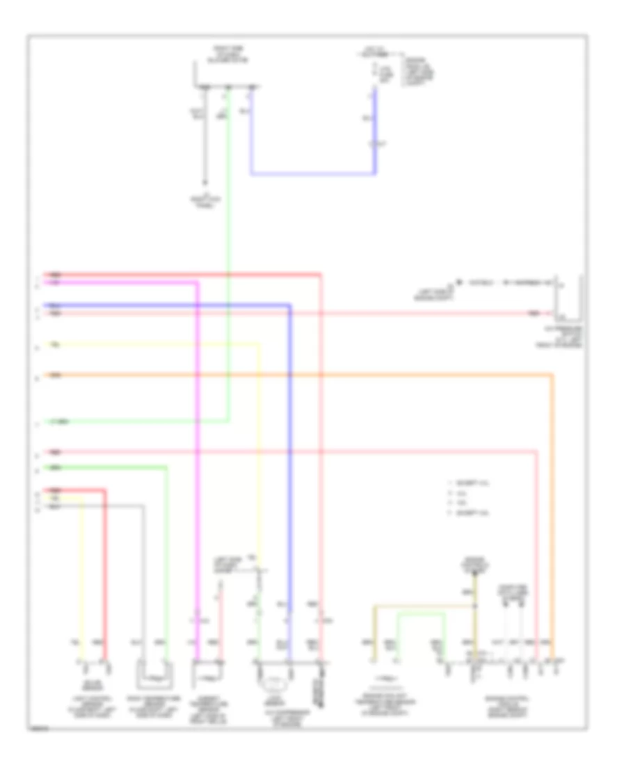
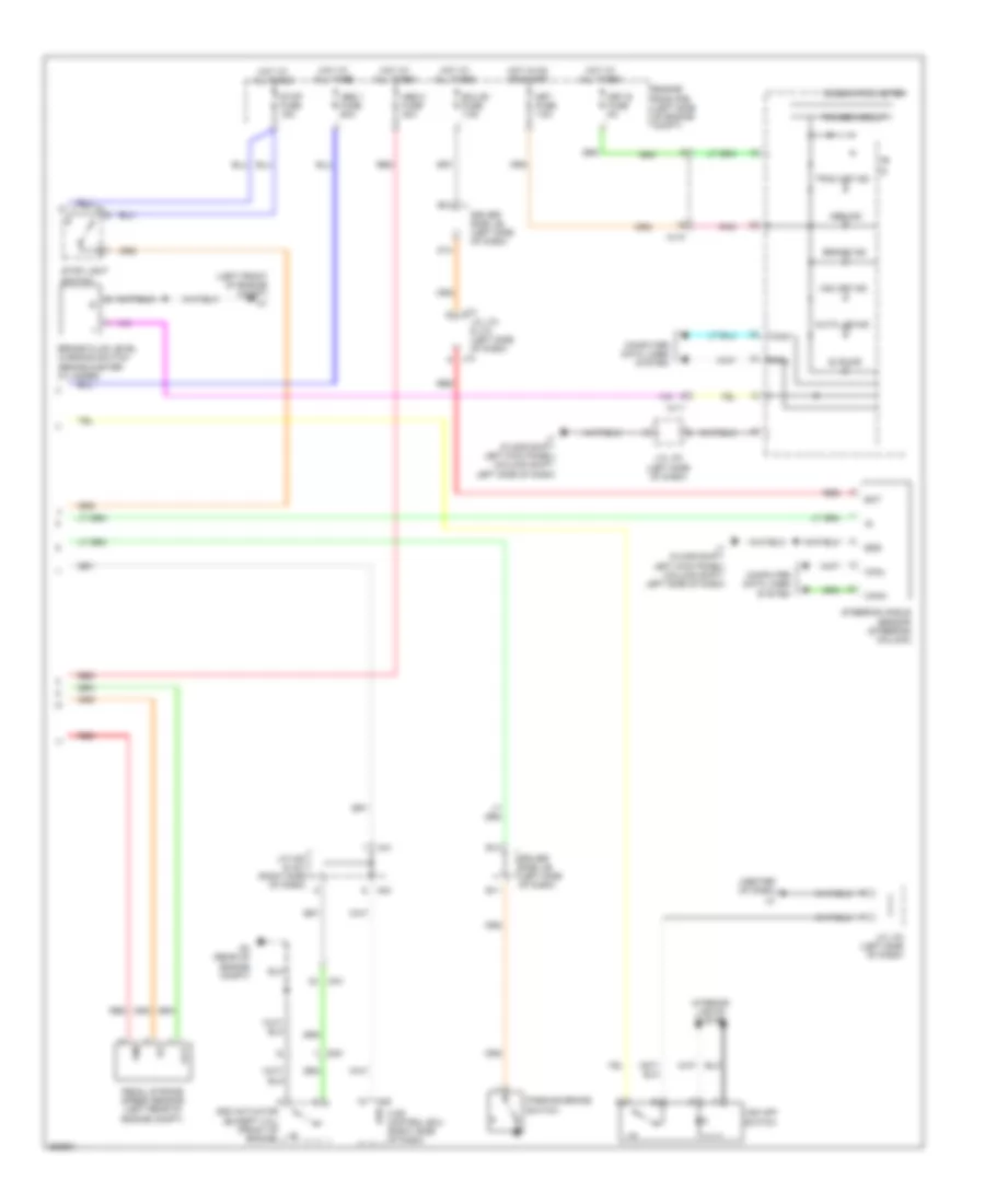
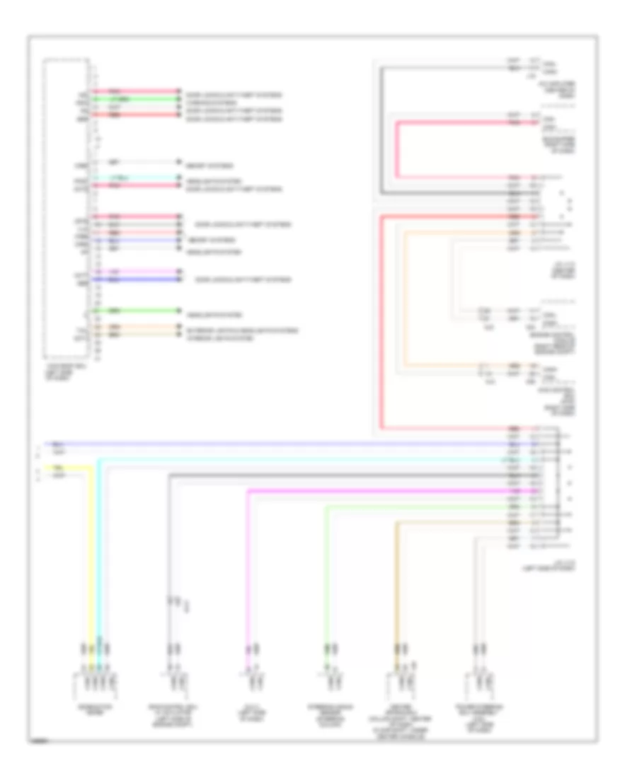
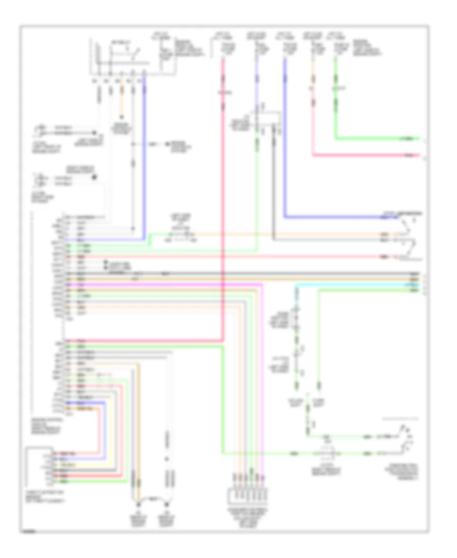
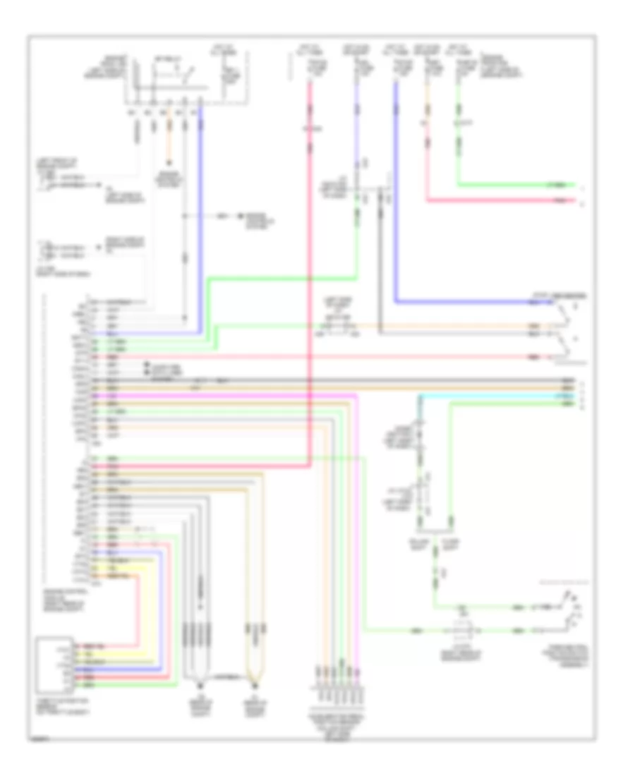
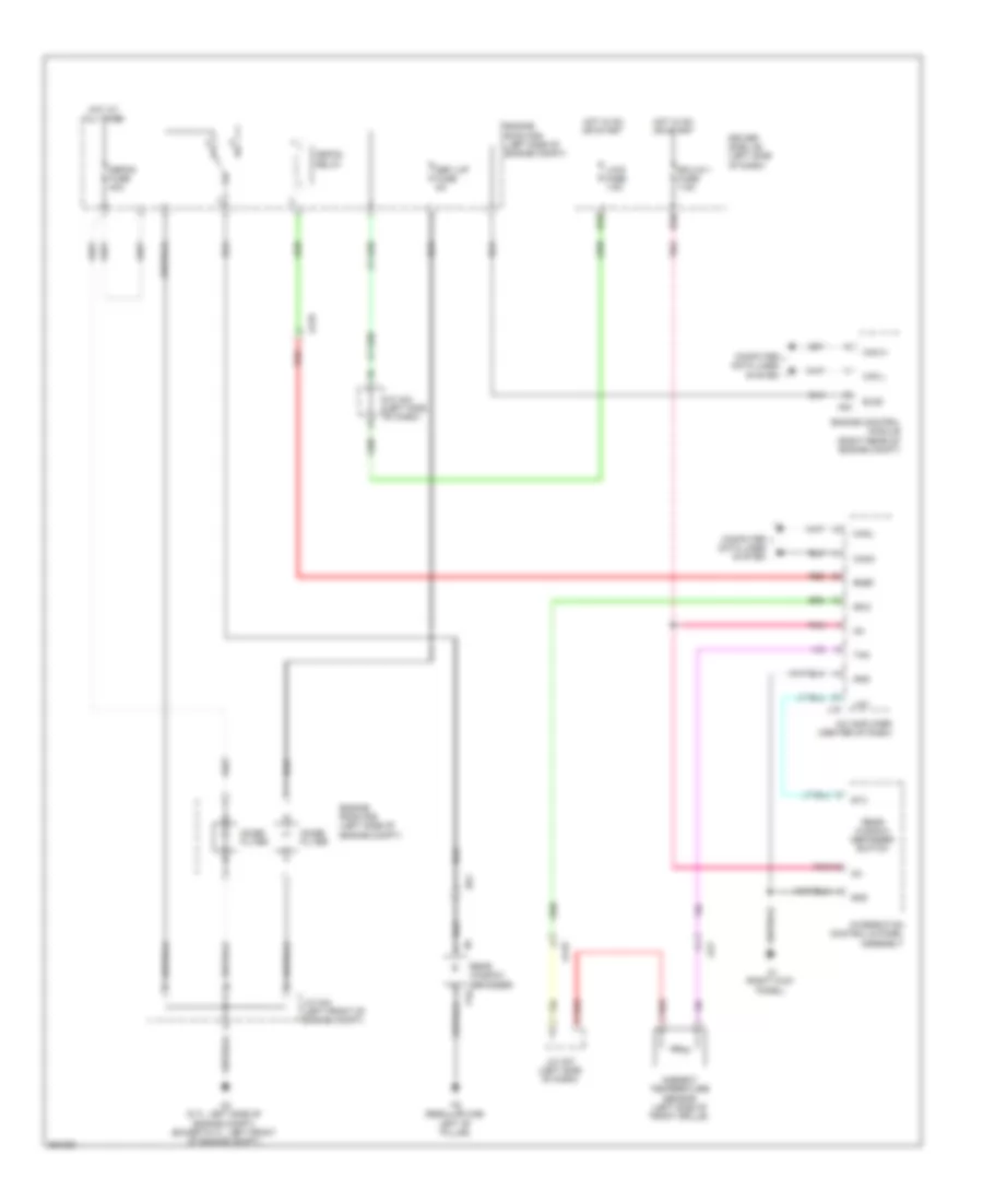
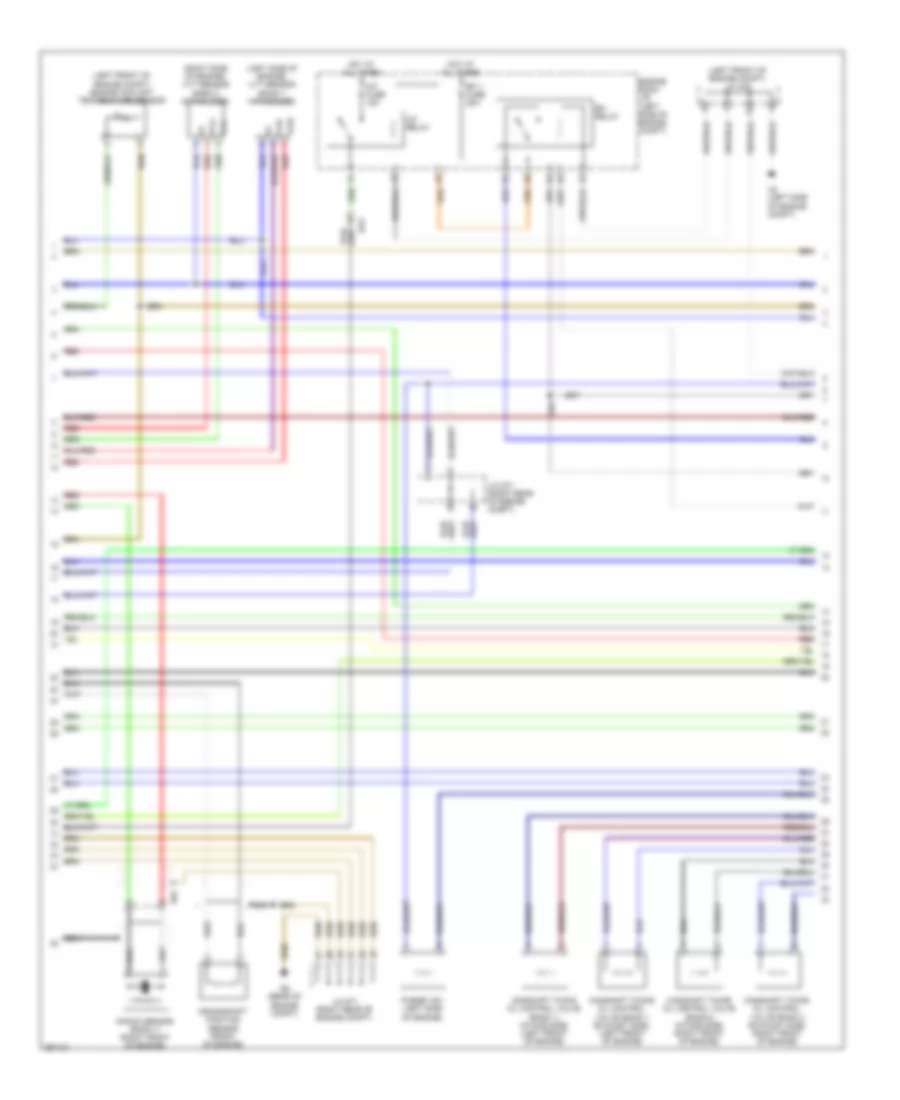
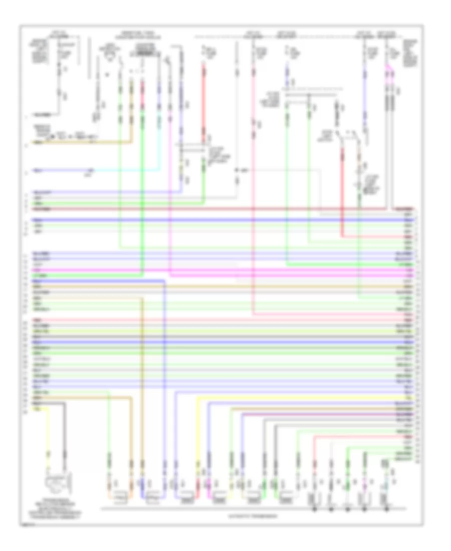
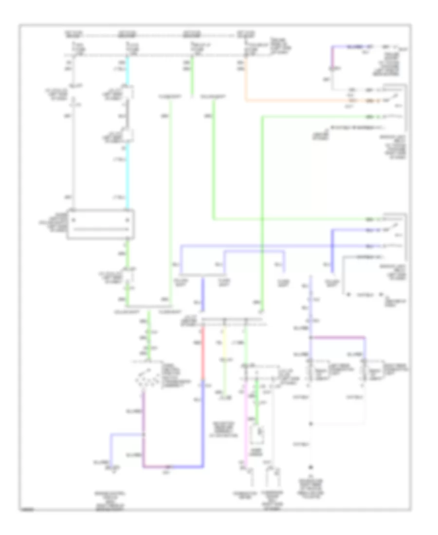
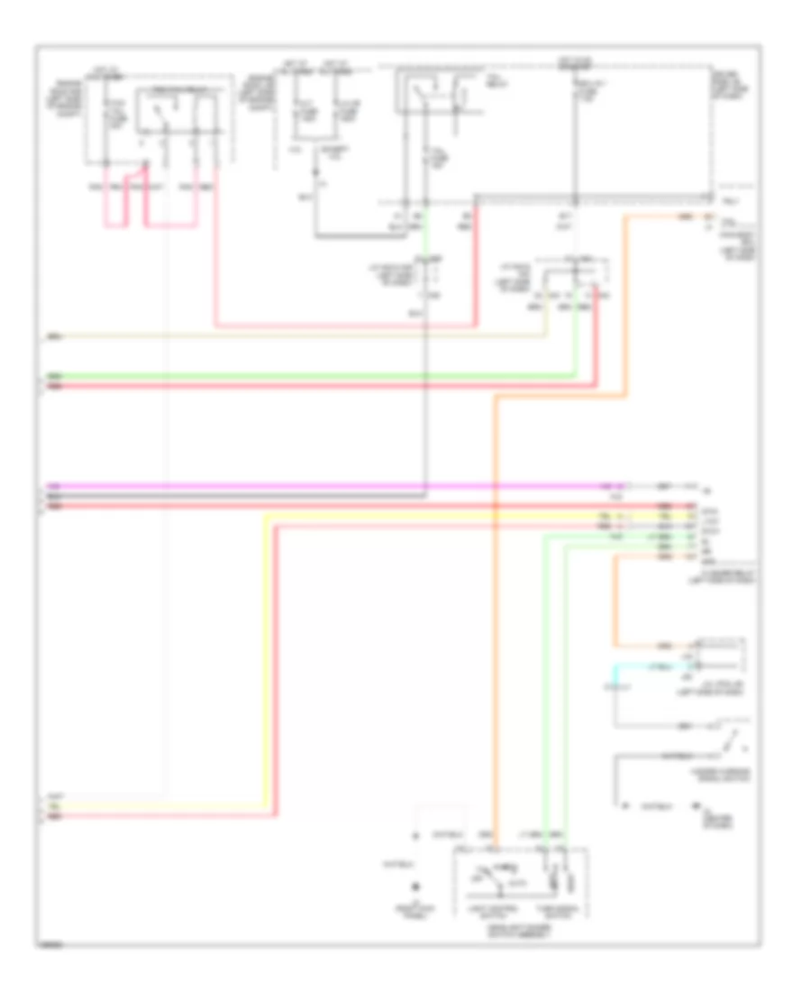
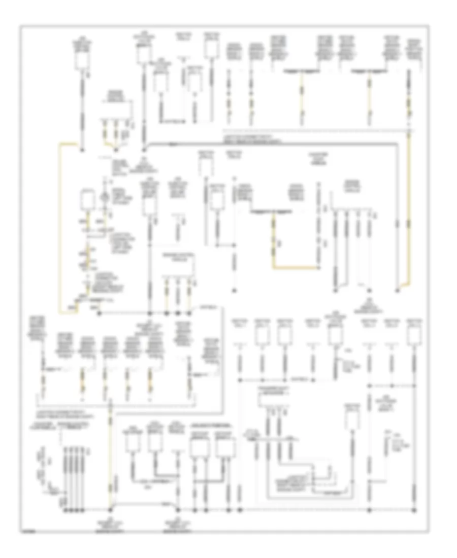
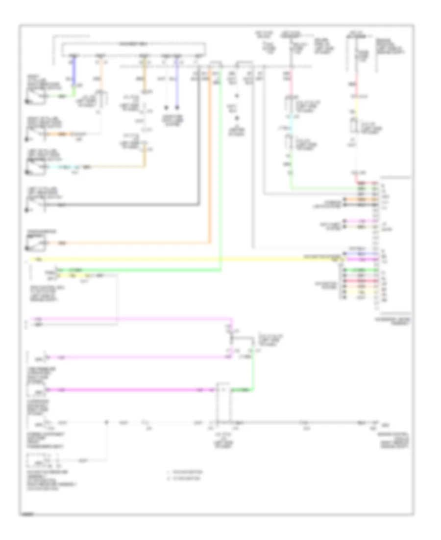
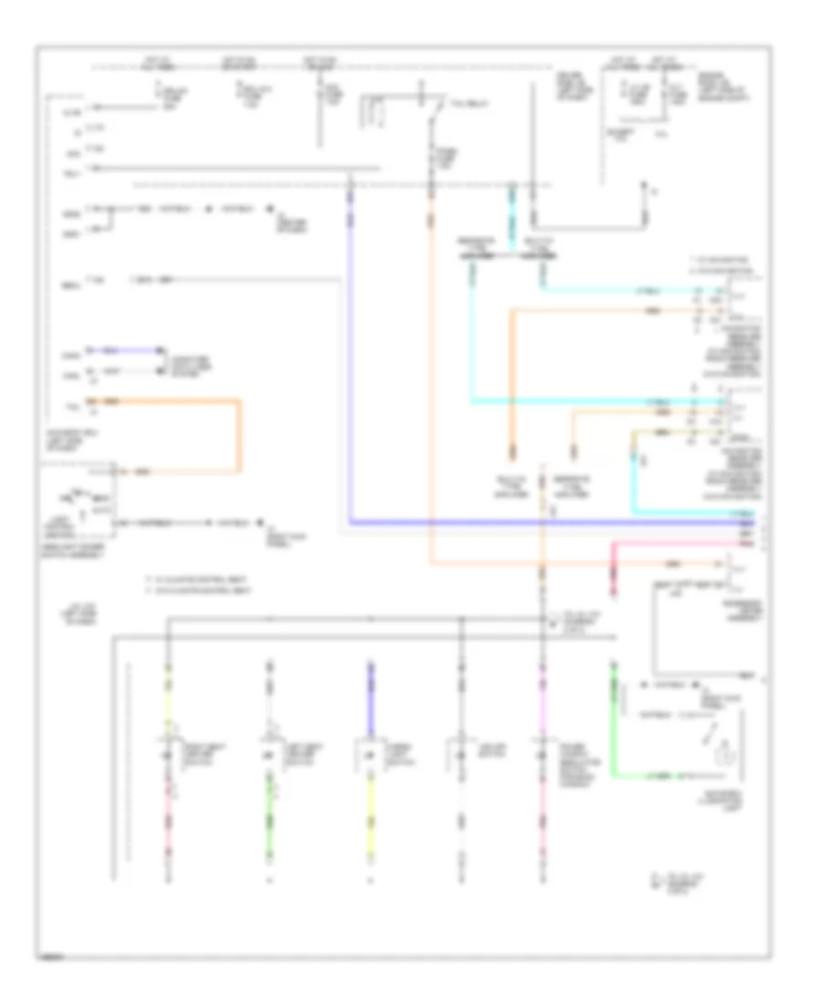
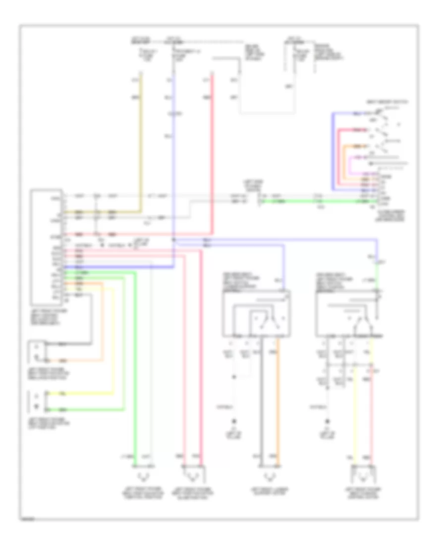
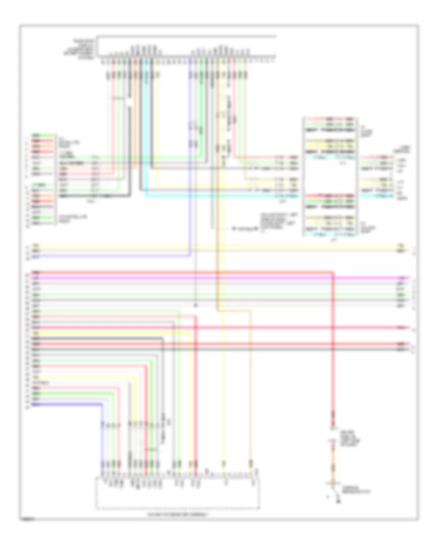
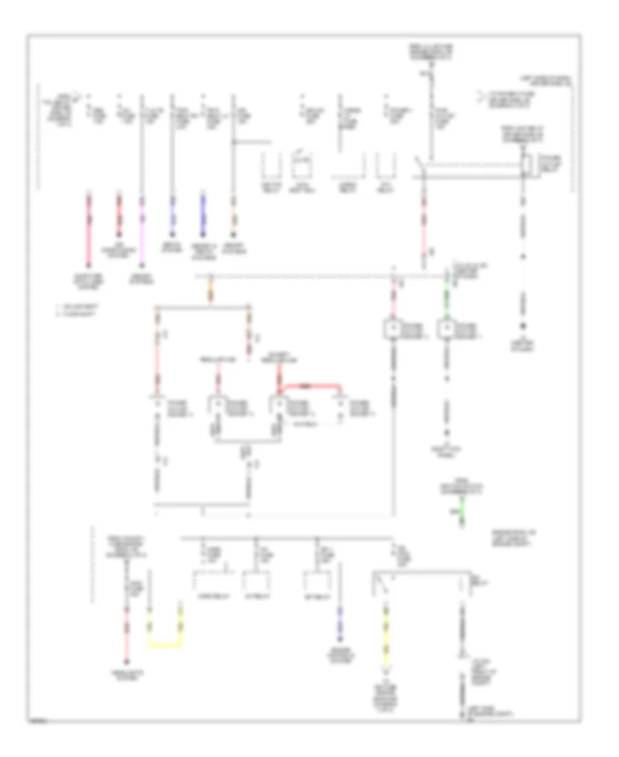
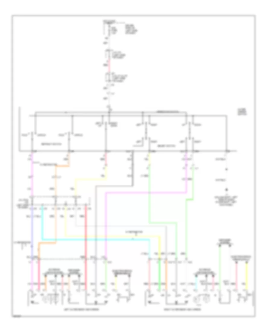
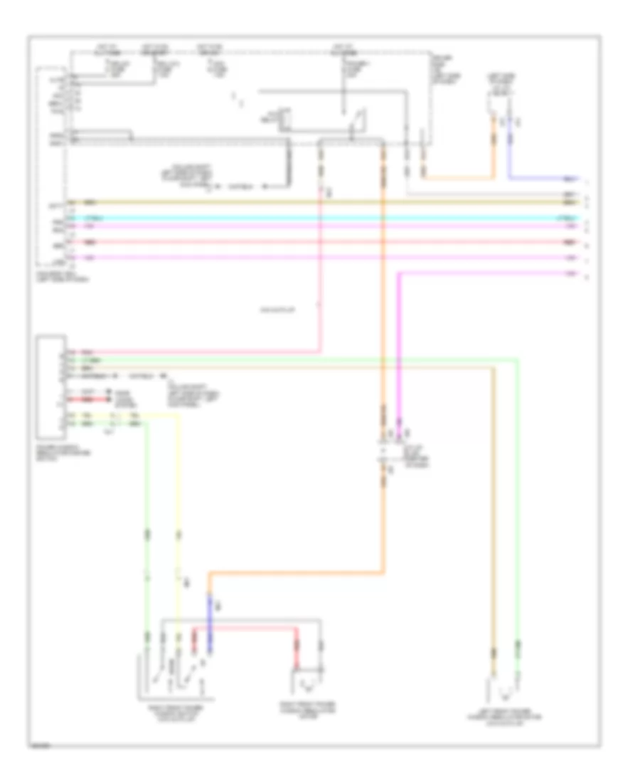
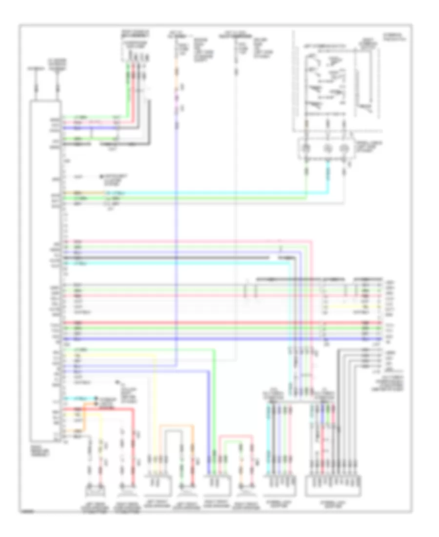
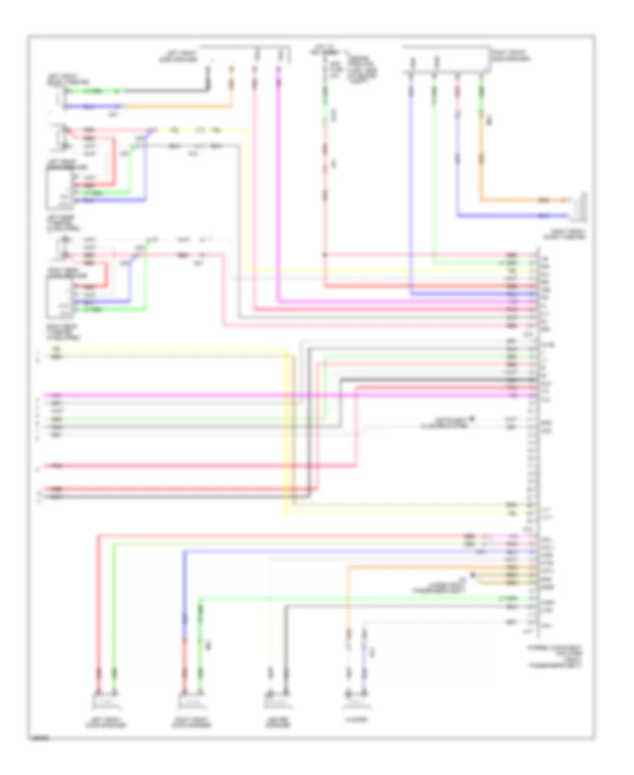
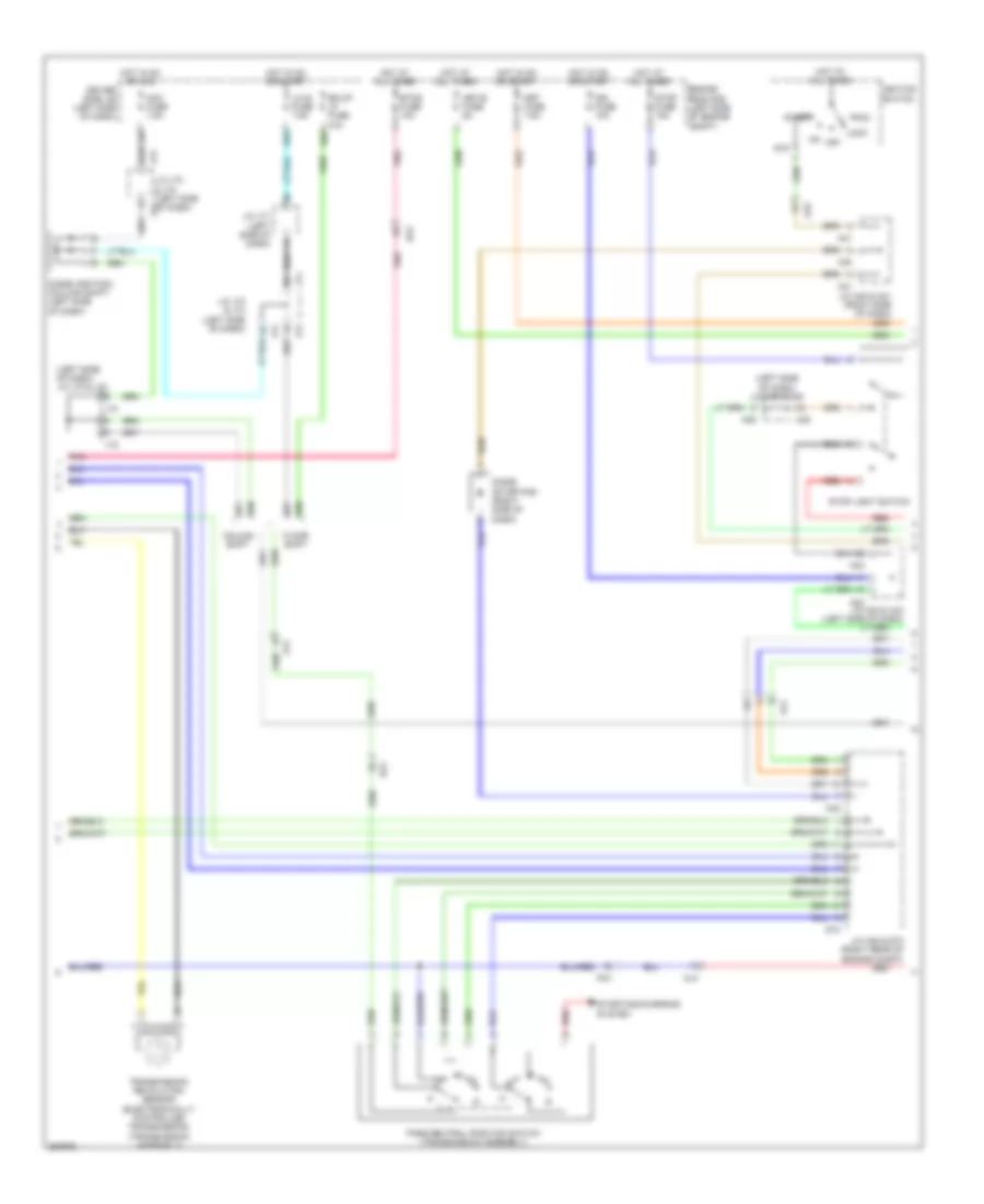
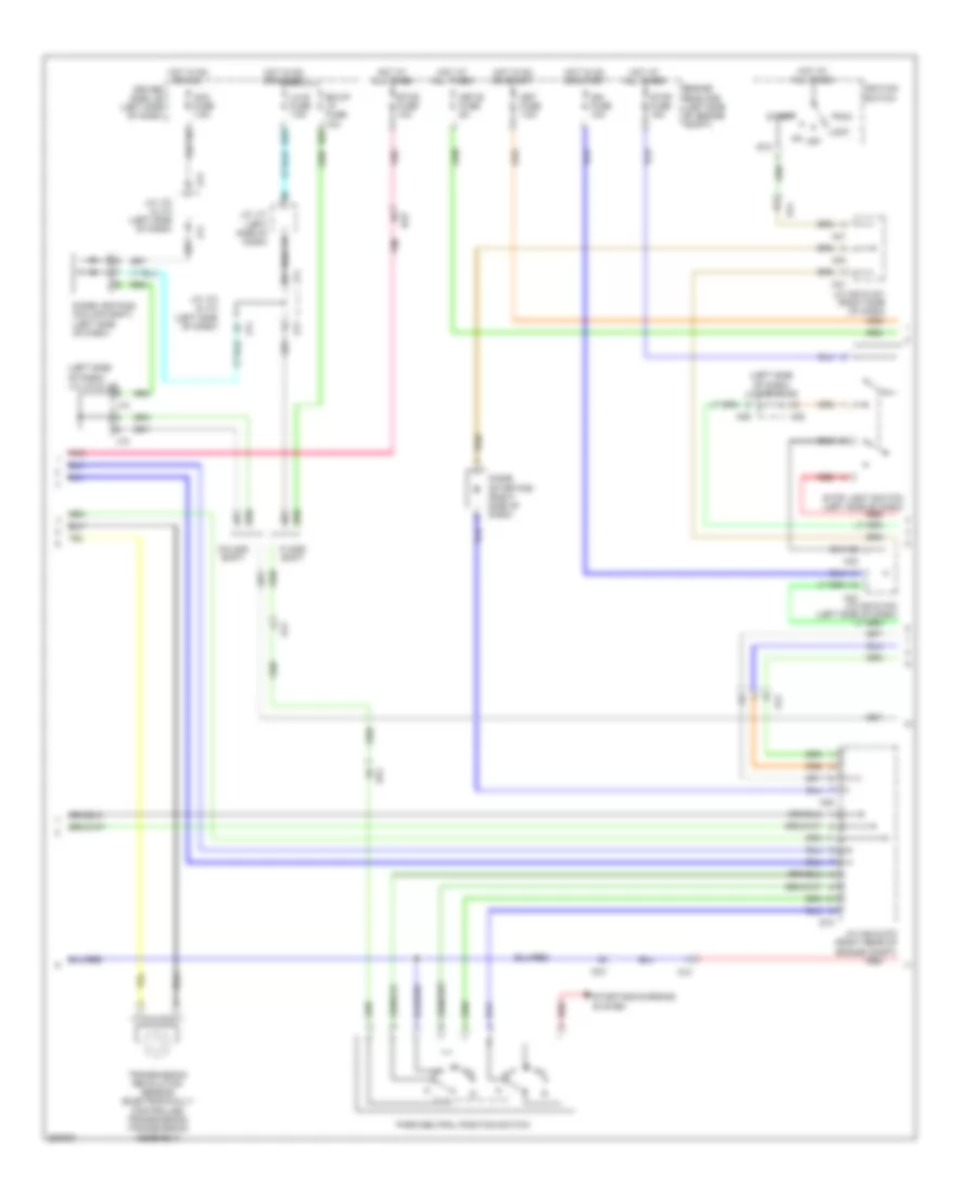
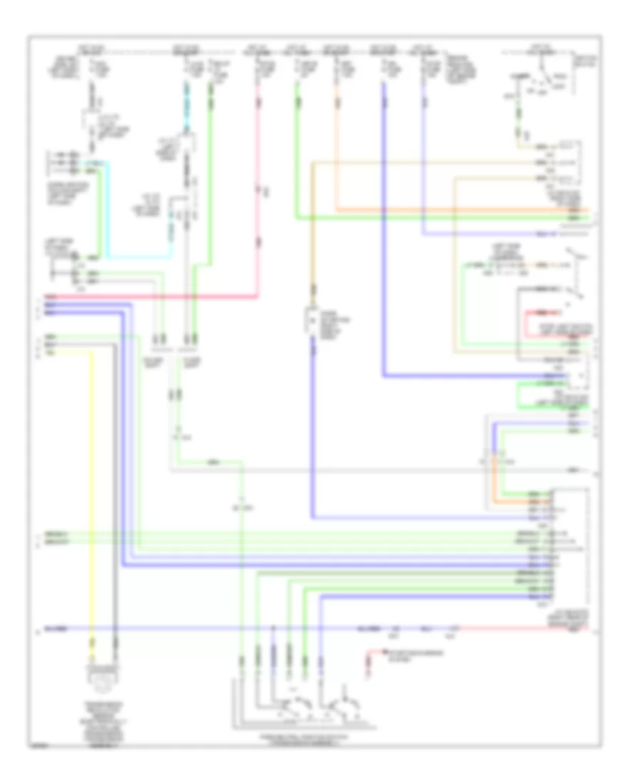
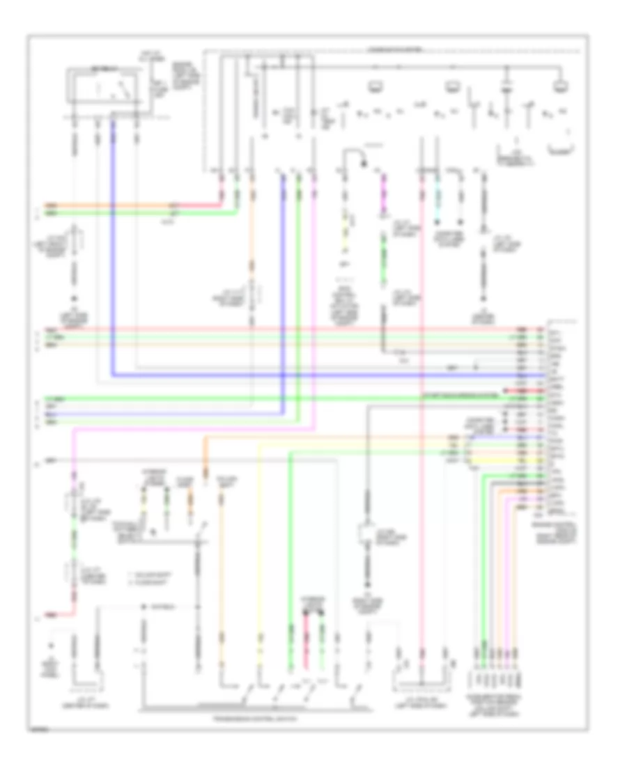
AIR CONDITIONING
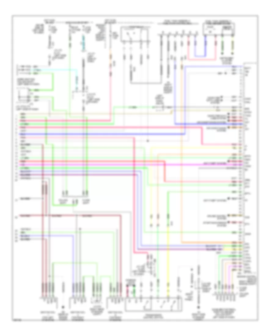
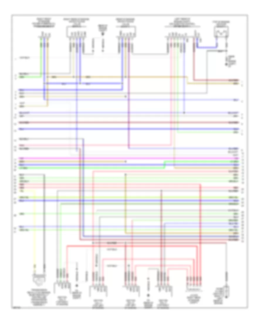
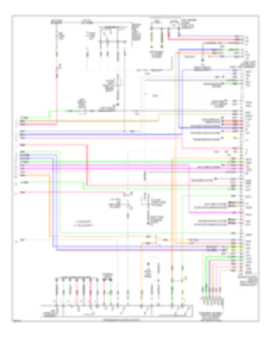
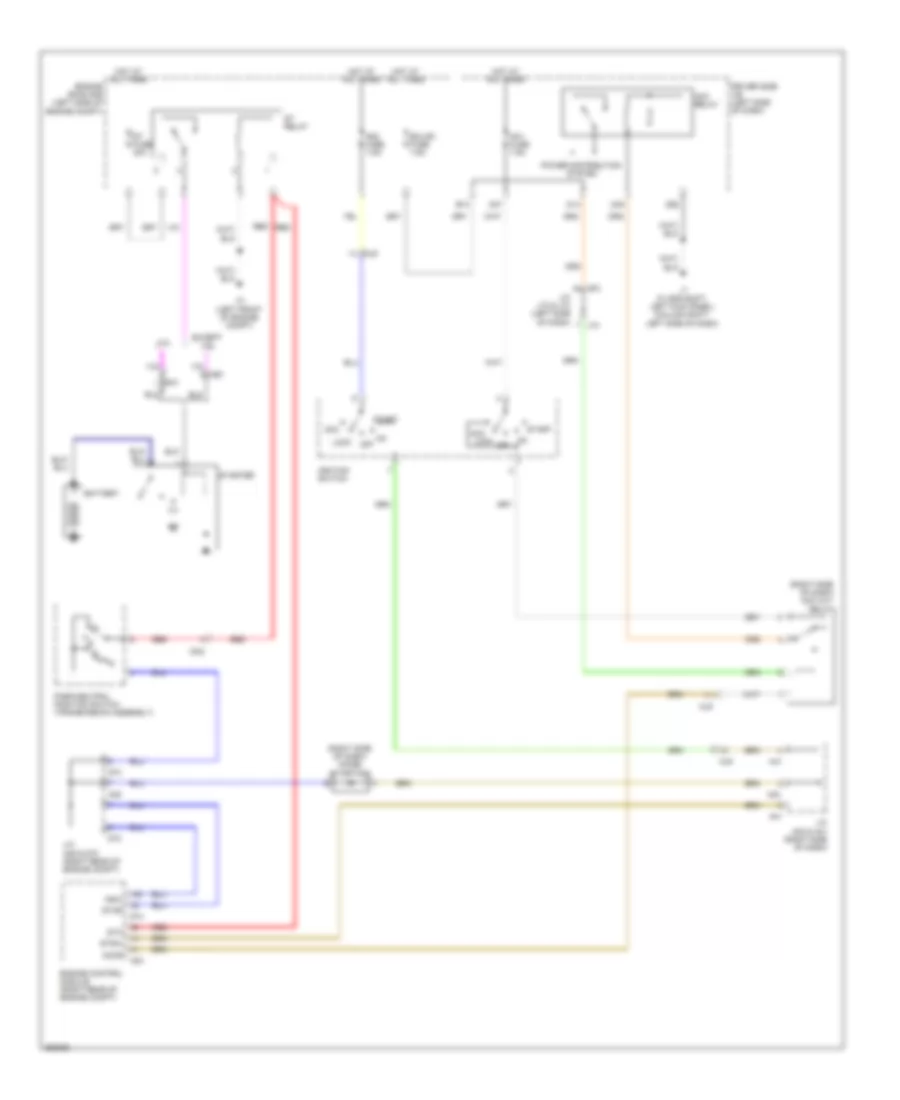
Automatic A/C Wiring Diagram (1 of 2) for Toyota Tundra SR5 2012
 https://portal-diagnostov.com/license.html
Automotive Electricians Portal FZCO
Automotive Electricians Portal FZCO
https://portal-diagnostov.com/license.html
https://portal-diagnostov.com/license.html
Automotive Electricians Portal FZCO
Automotive Electricians Portal FZCO
List of elements for Automatic A/C Wiring Diagram (1 of 2) for Toyota Tundra SR5 2012:
- (right kick panel) j3
- A/c amplifier (center of dash)
- A/c blower assembly (floor shift: right side of dash)
- A/c evaporator temperature sensor
- A/c fuse 7.5a
- A/c ig fuse 10a
- Ac1
- Act
- Ad-4
- Ad-5
- Aj10
- Aj3
- Aj5
- B bus
- Blw
- Bus
- Bus g
- Canh
- Canl
- Computer data lines system
- Connector housing color (black)
- Connector housing color (green)
- Connector housing color (natural)
- Connector housing color (red)
- D56
- D58
- Damper servo motor (air inlet)
- Damper servo motor (air mix driver side)
- Damper servo motor (air mix front passenger side)
- Damper servo motor (air vent mode)
- Damper servo motor (cool air bypass)
- Defogger system
- Driver side j/b (left side of dash)
- Ecu ig 1 fuse 7.5a
- Engine room r/b (left side of engine compartment)
- Gnd
- Hot at all times
- Hot in on or start
- Ig+
- Integration control & panel assembly
- J106
- J19
- J3 (right kick panel)
- Jk1
- Jk2
- Lin1
- Lock
- Mg clt relay
- Mgc
- Mhtr
- Pnk
- Psw
- Rdef
- Red
- S5-2
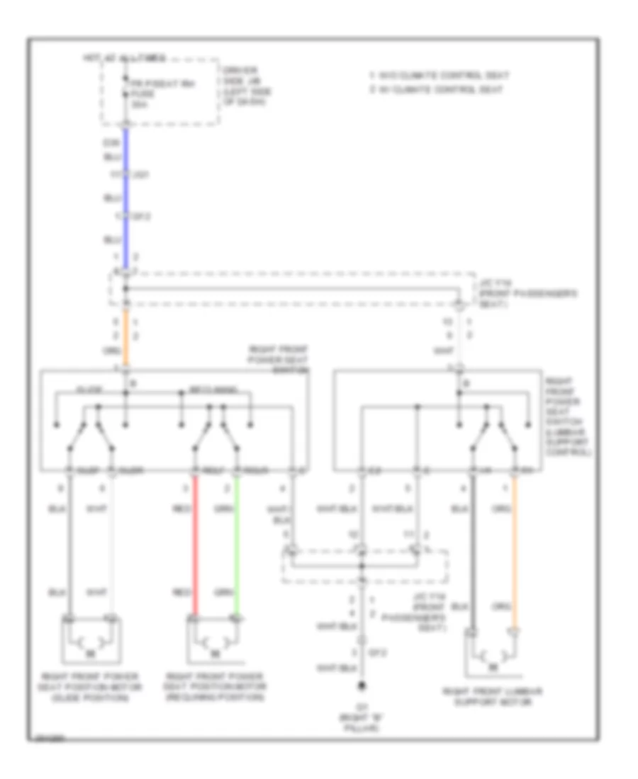
- Seats system
- Sg 1
- Sg 2
- Sg-5
- Sga
- Shd+
- Shp+
- Stx
- Tam
- Tea
- Tsd
- Tsp
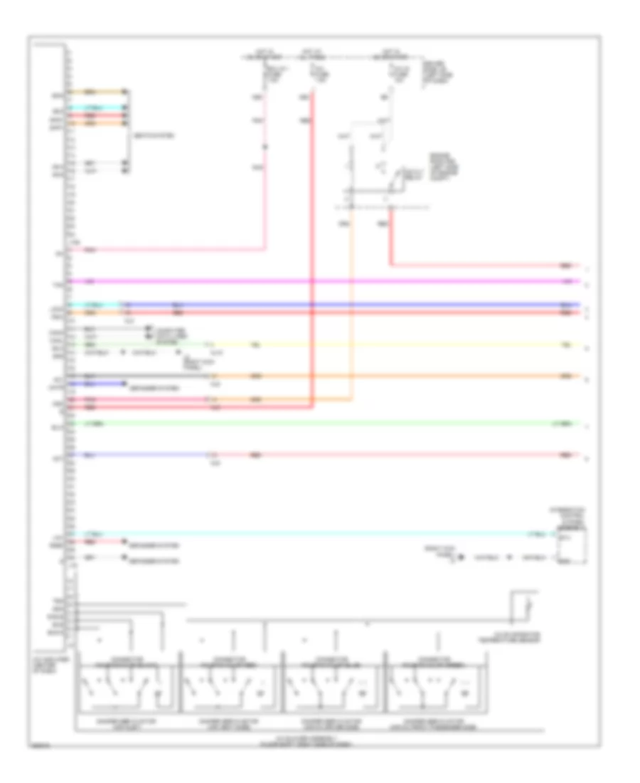
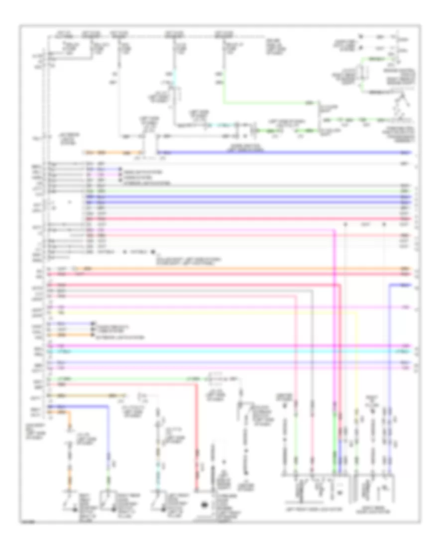
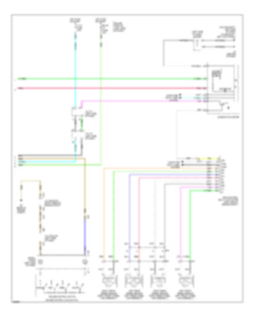
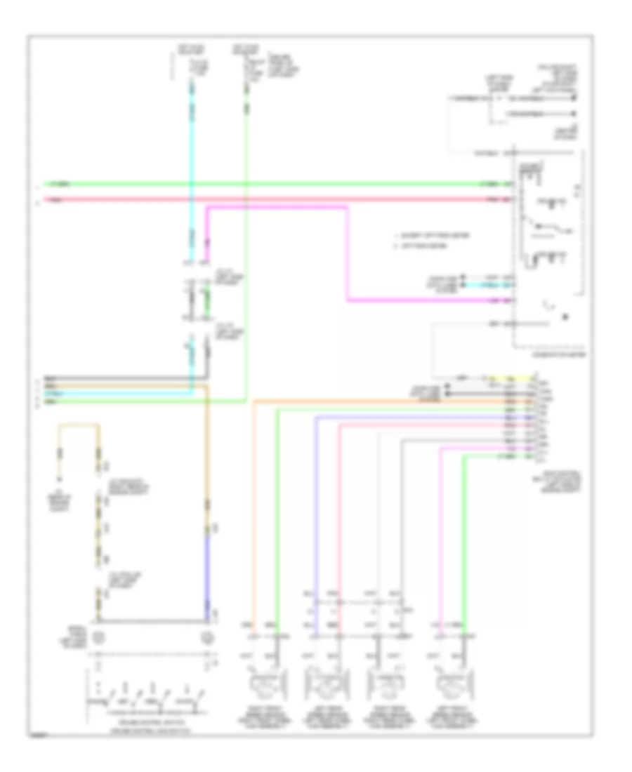
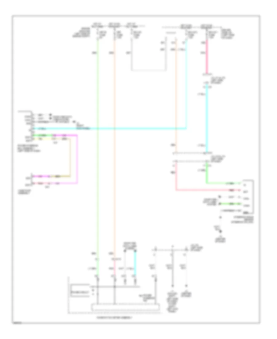
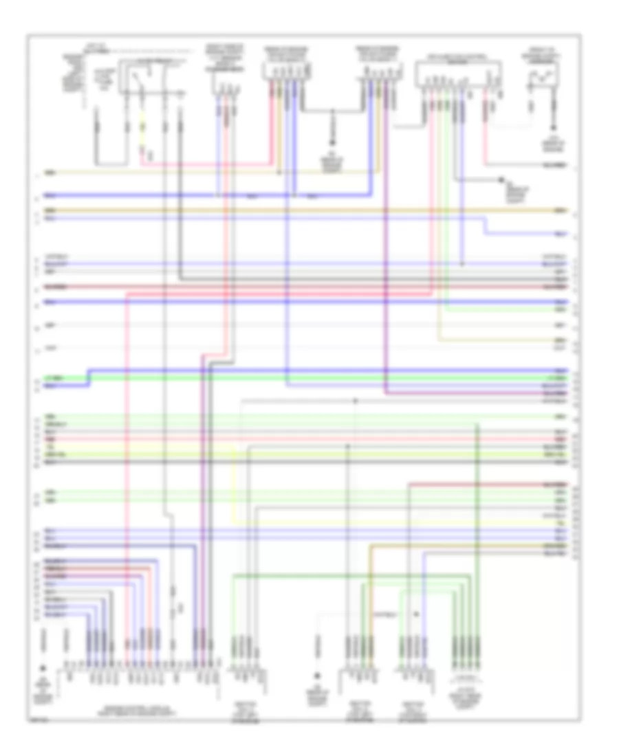
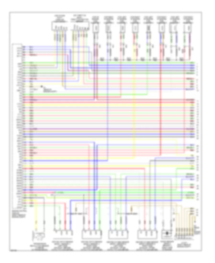
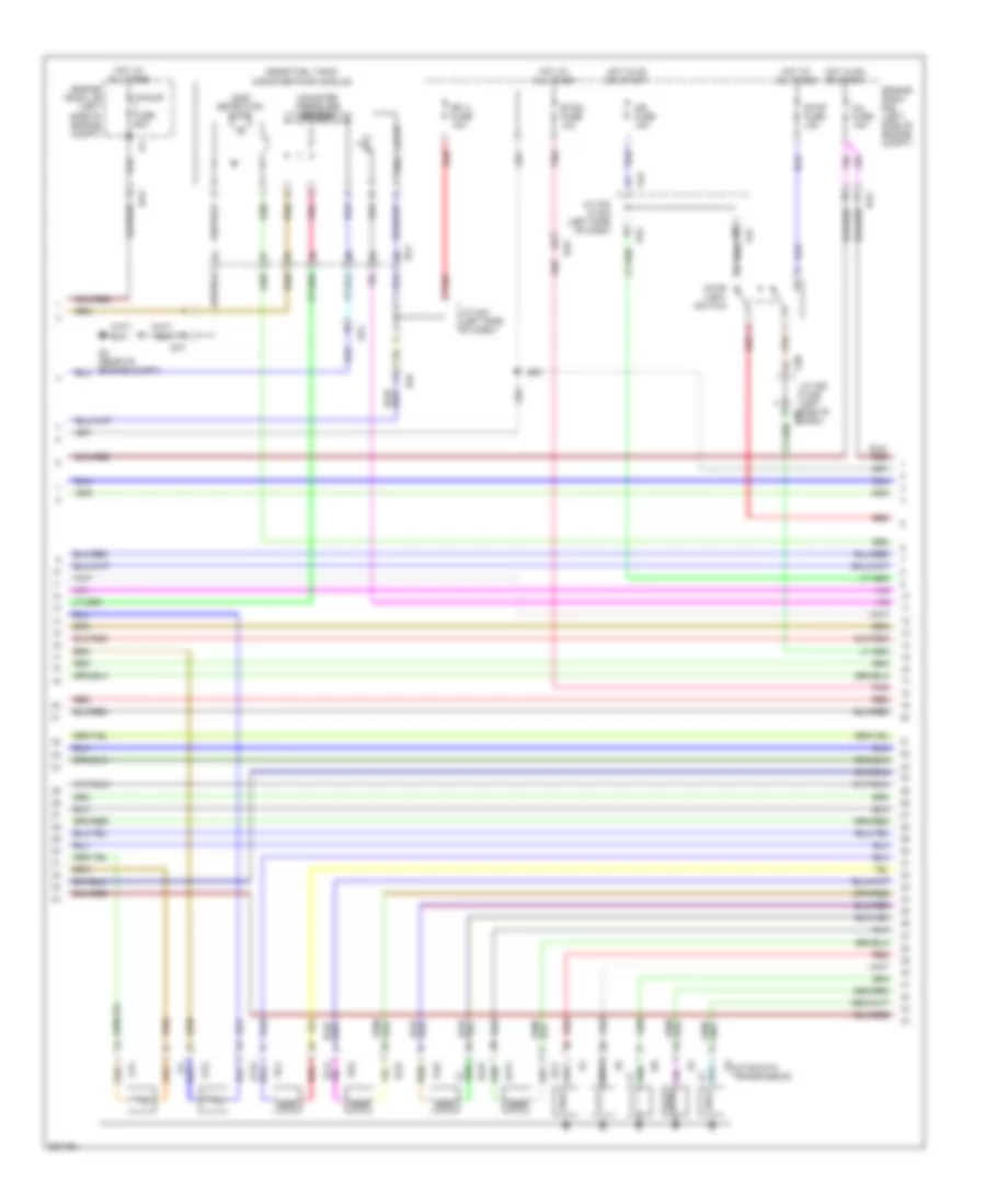
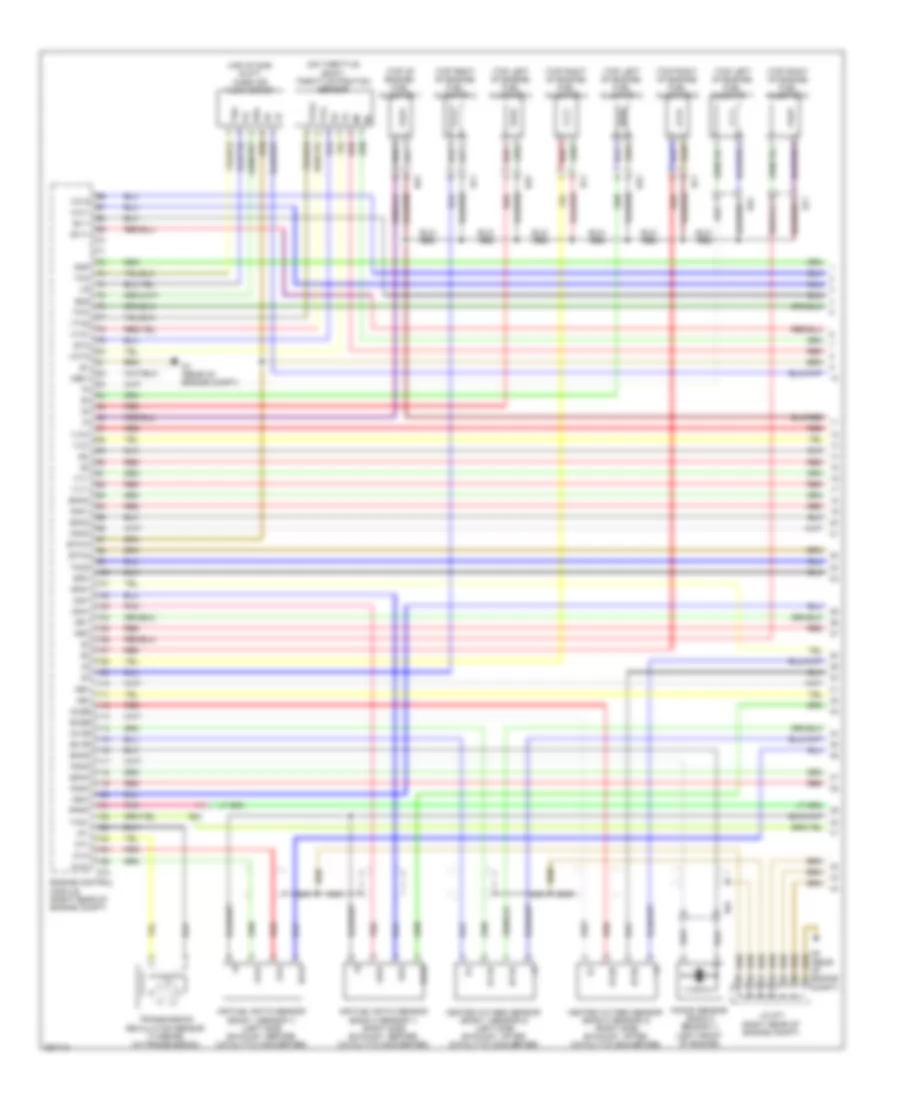
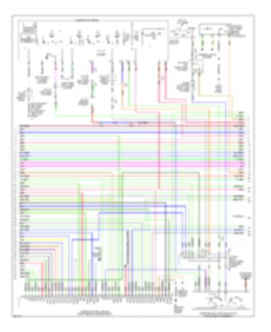
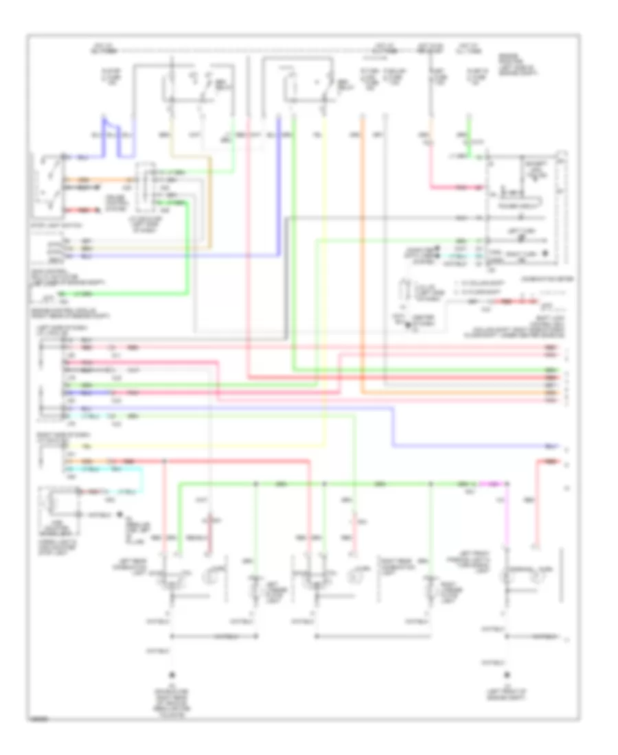
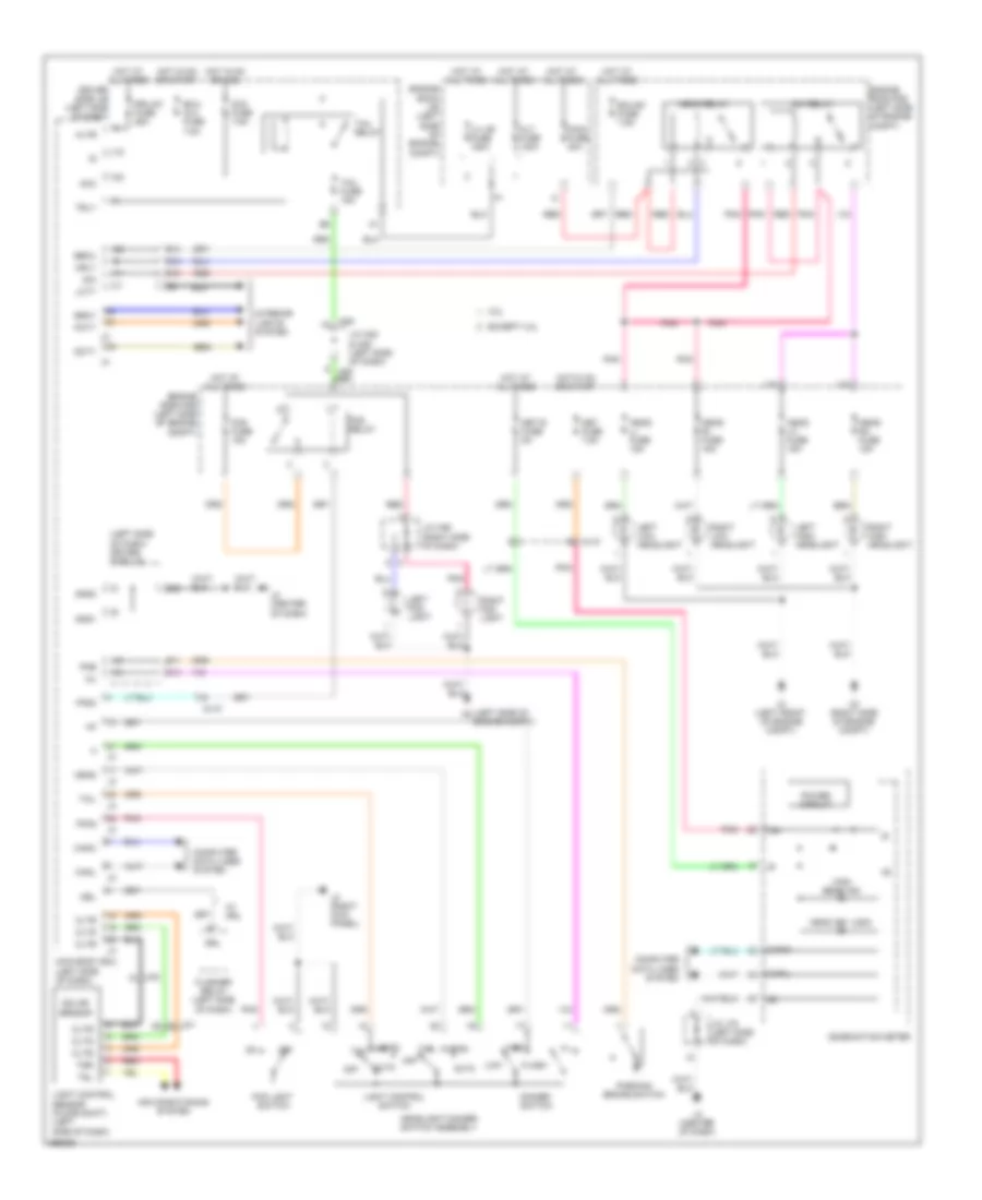
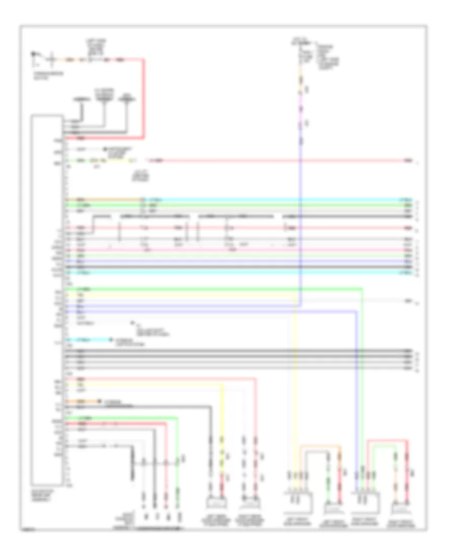
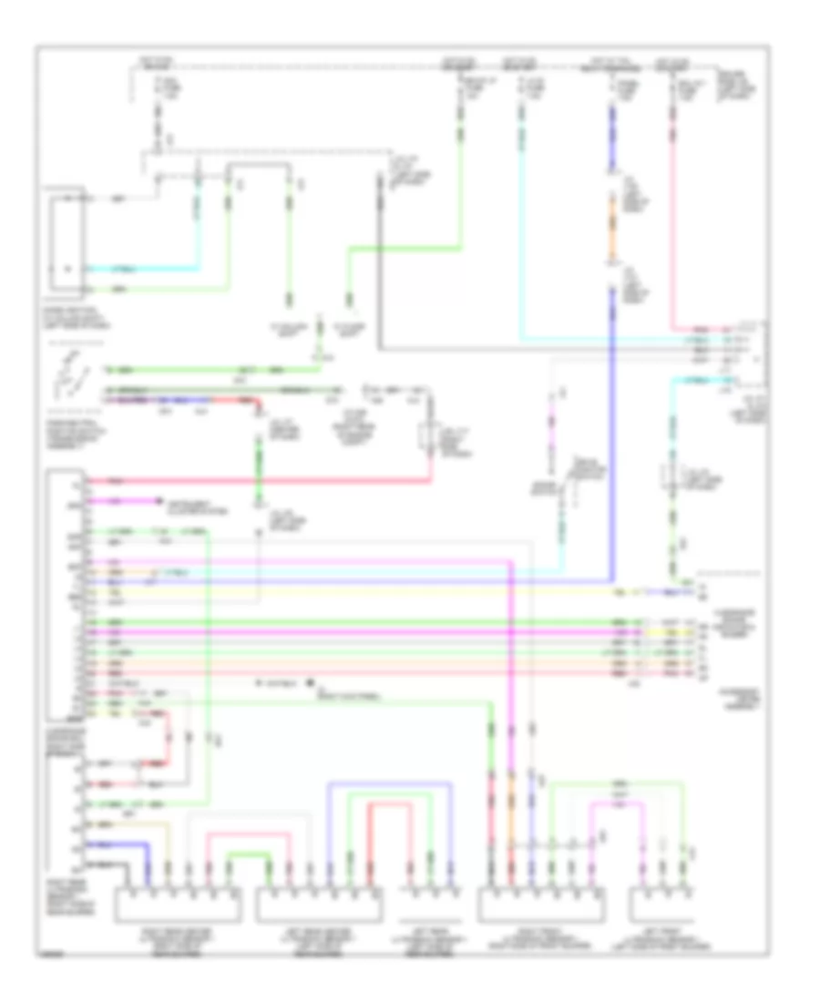
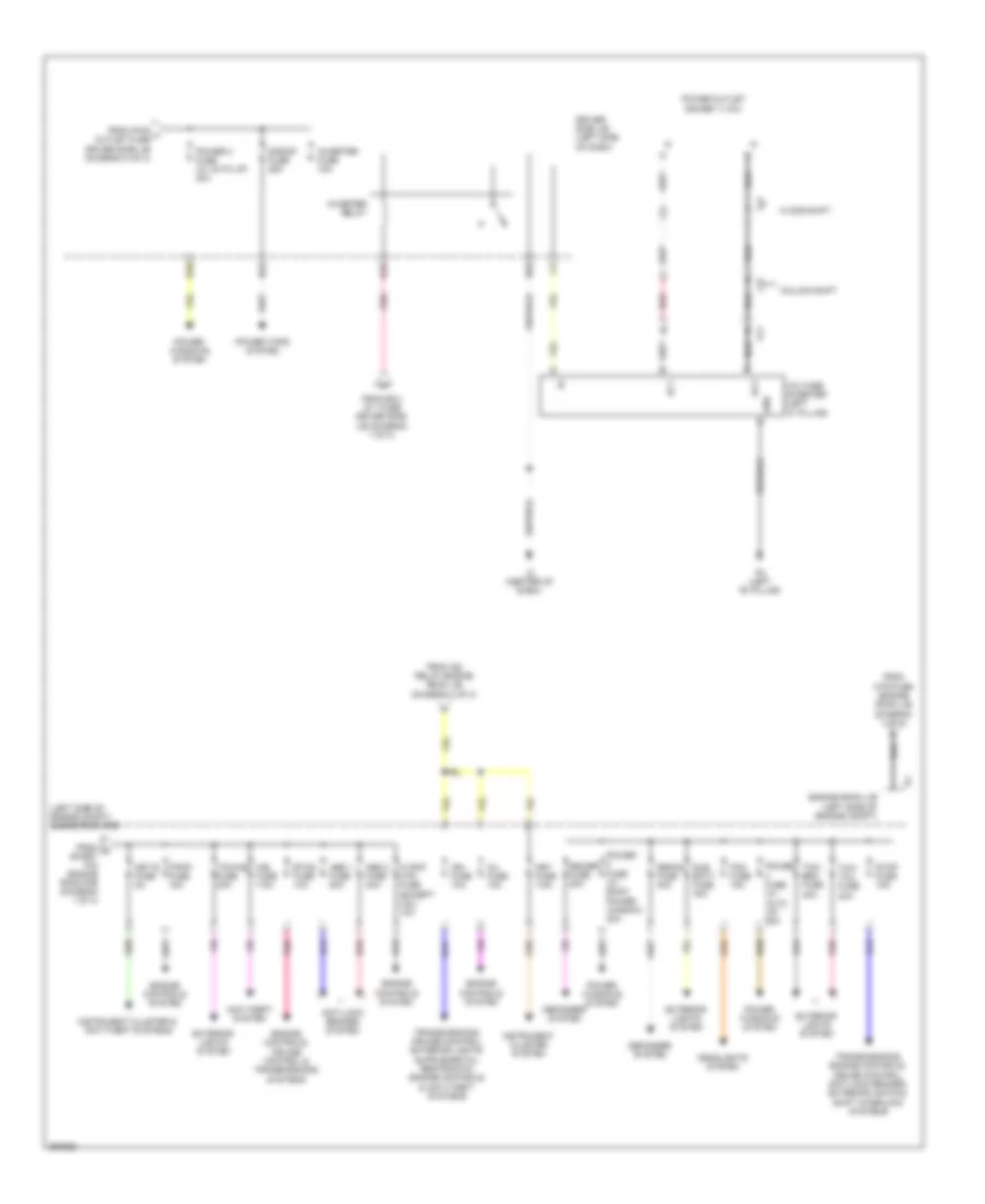
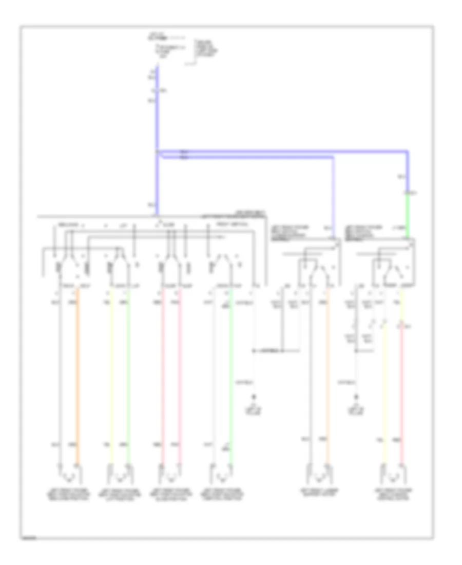
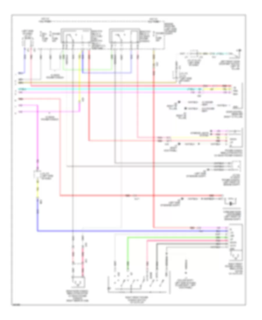
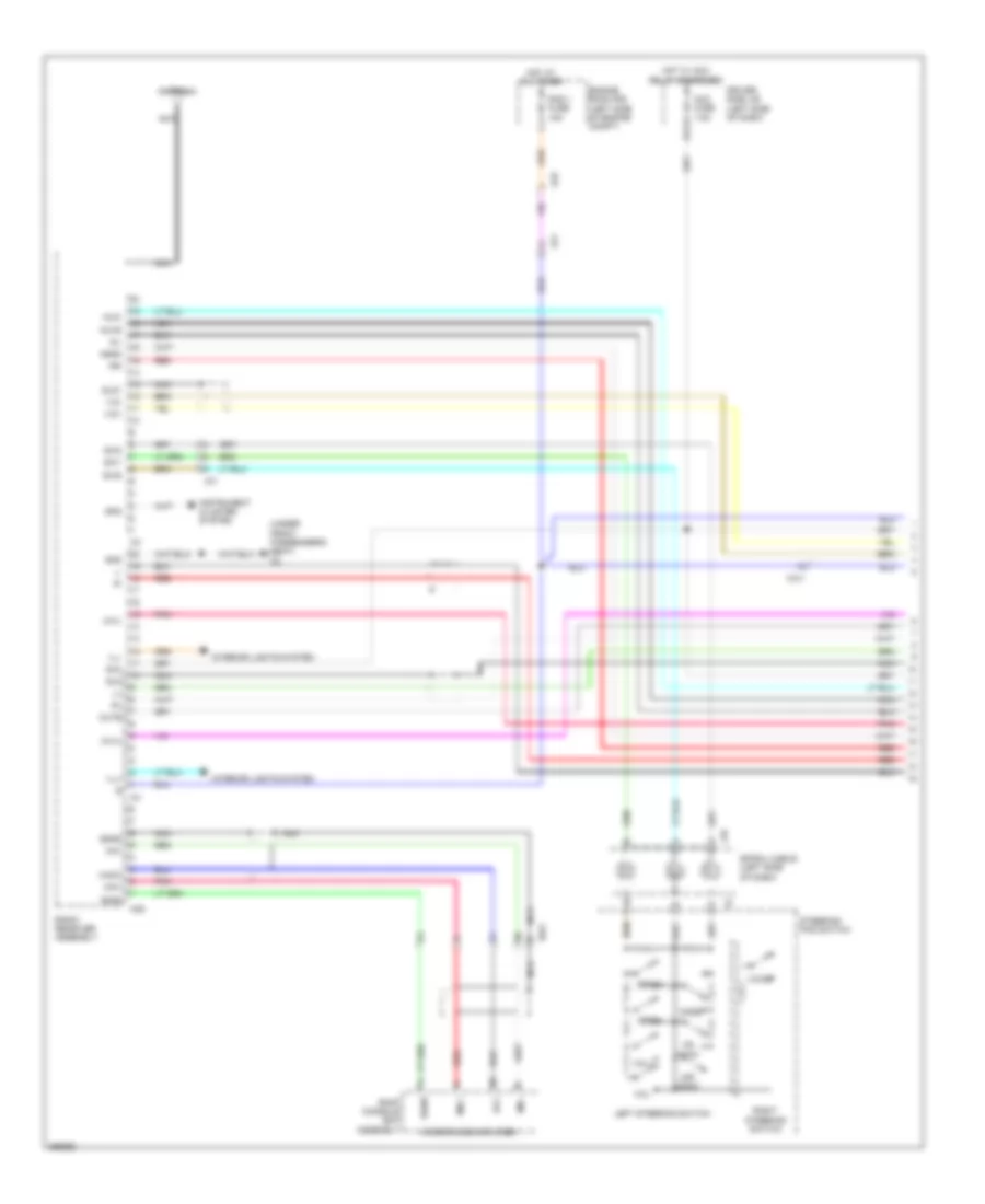
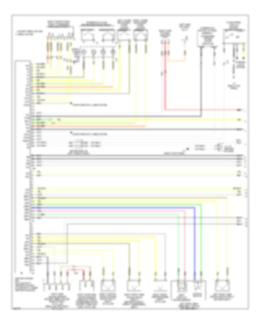
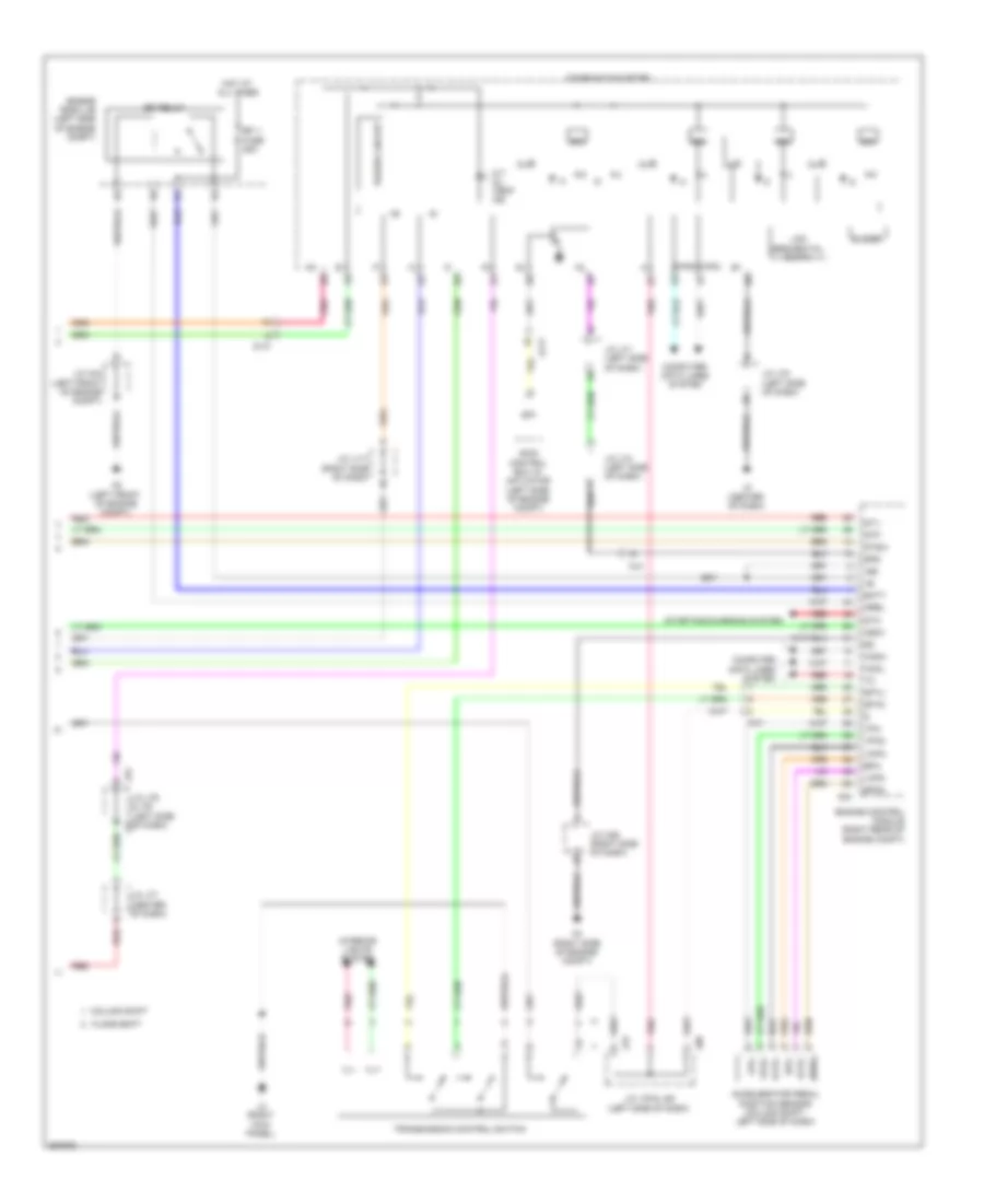
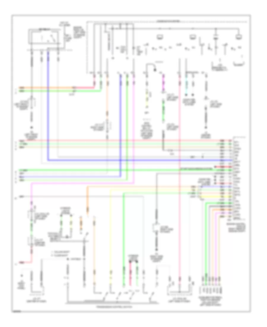
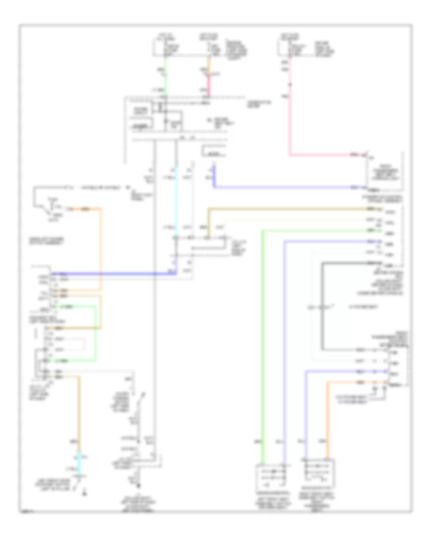
Automatic A/C Wiring Diagram (2 of 2) for Toyota Tundra SR5 2012
List of elements for Automatic A/C Wiring Diagram (2 of 2) for Toyota Tundra SR5 2012:
- (left side of dash) j/c a37
- (right side of dash) blower motor
- 4.0l
- 4.6l
- A/c compressor (left front of engine)
- A/c pressure switch (5.7l: left front of engine)
- A2 (left side of engine compt)
- A24
- Ac1
- Act
- Aj3
- Aj7
- Ambient temperature sensor (left side of front grille)
- Canh
- Canl
- Computer data lines system
- D74
- Da3
- E2 ethw
- Engine control module (right rear of engine compt)
- Engine controls system
- Engine coolant temperature sensor (left front of engine compt)
- Engine room j/b (left side of engine compt)
- Except 4.0l
- Except 4.6l
- Gnd
- Hot at all times
- Htr fuse 50a
- J3 (right kick panel)
- Light control sensor (floor shift: left side of dash)
- Lock sensor
- Magnetic clutch
- Mg+
- Red
- Room temperature sensor (floor shift: left side of dash)
- Solar sensor
- Ssr+
- Ssr-
- Thw
- Tsl
- Tsr
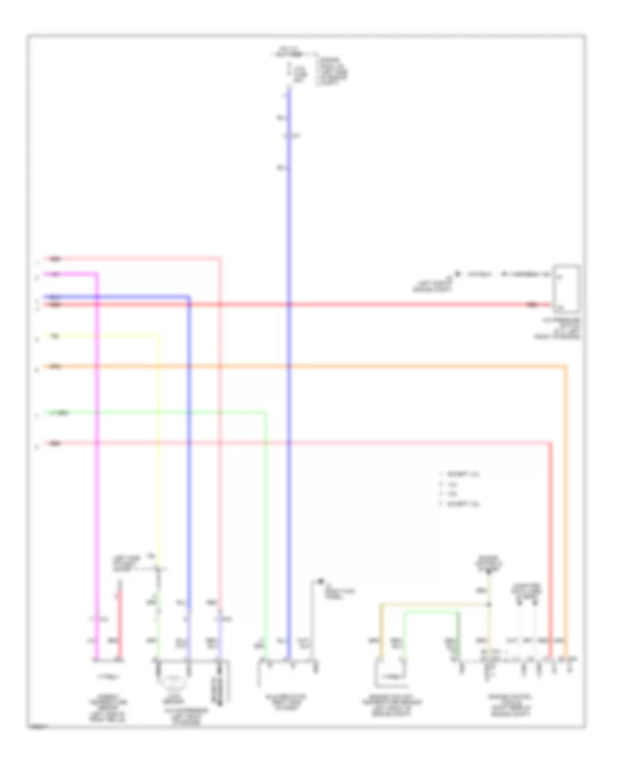
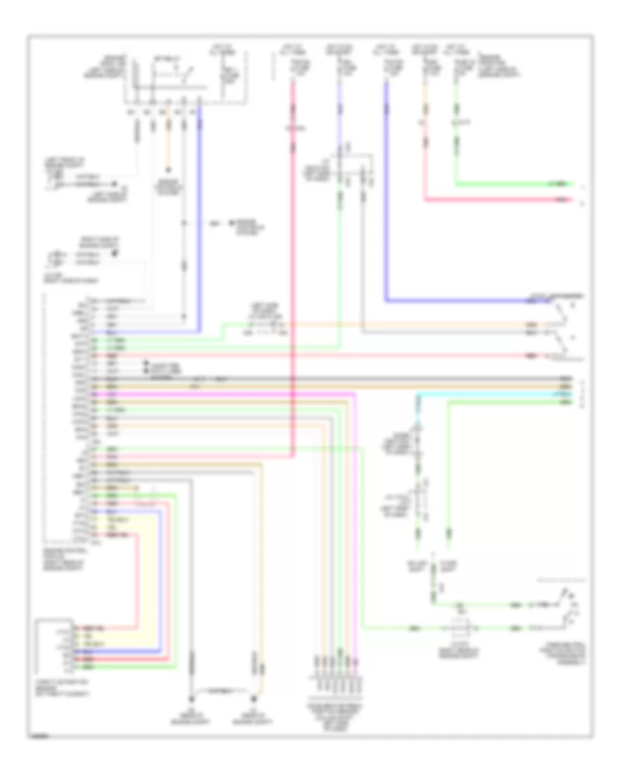
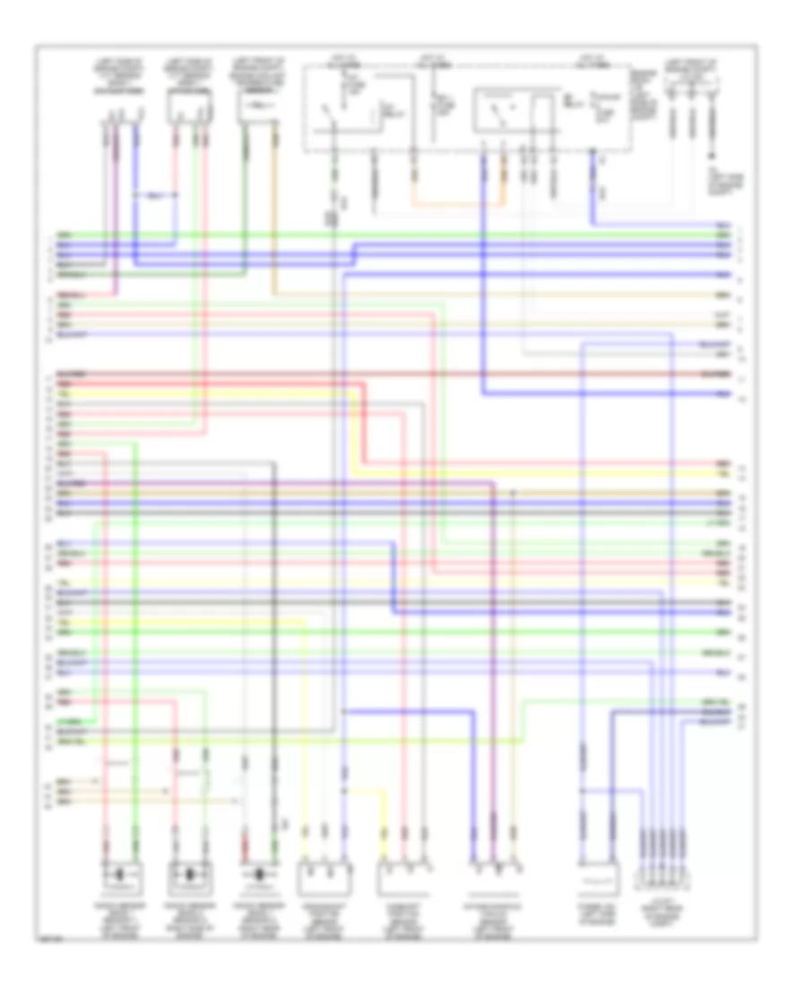
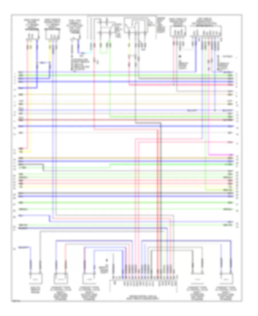
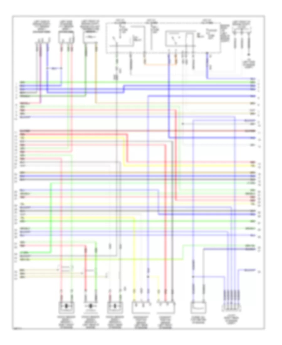
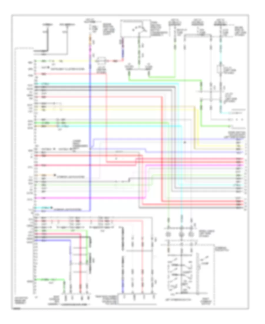
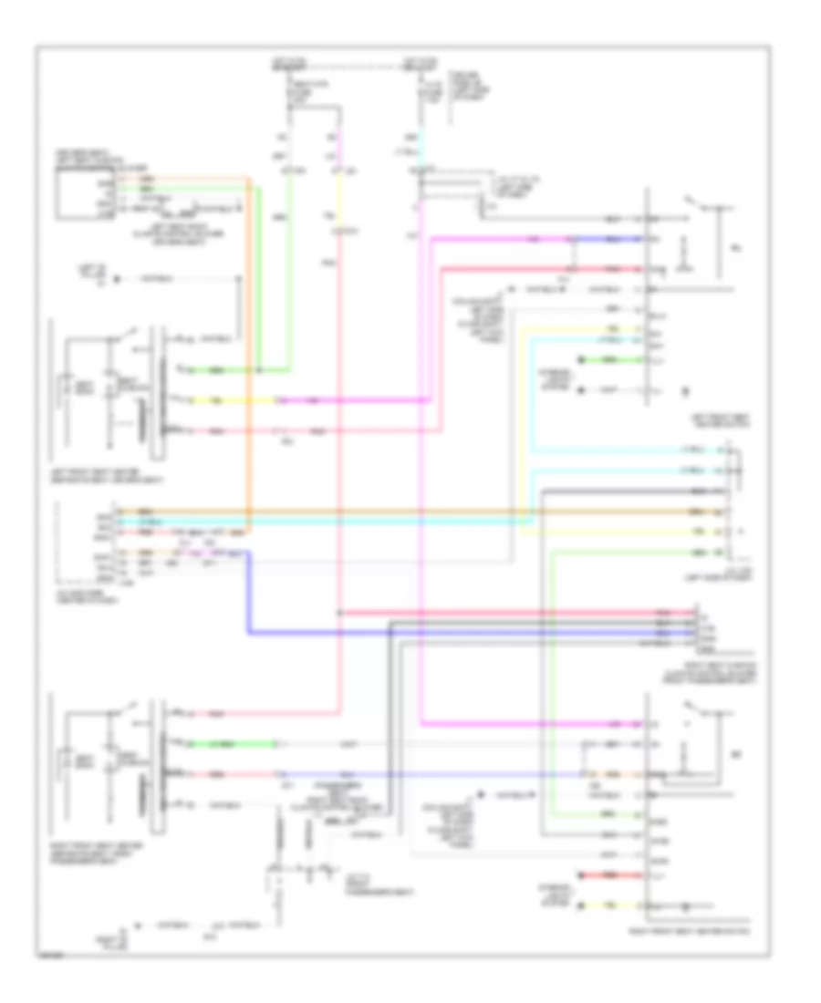
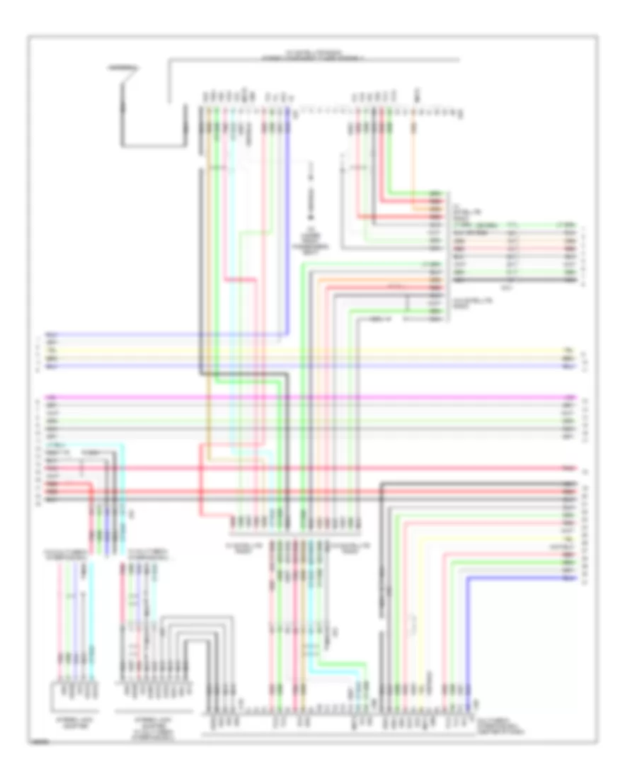
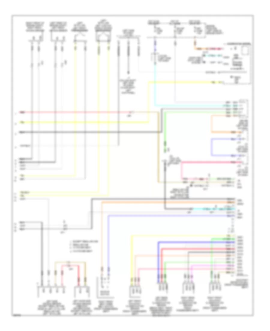
Manual A/C Wiring Diagram (1 of 2) for Toyota Tundra SR5 2012
List of elements for Manual A/C Wiring Diagram (1 of 2) for Toyota Tundra SR5 2012:
- (right kick panel) j3
- A/c amplifier (center of dash)
- A/c blower assembly (floor shift: right side of dash)
- A/c evaporator temperature sensor
- A/c fuse 7.5a
- A/c ig fuse 10a
- Ac1
- Act
- Ad-4
- Ad-5
- Aj10
- Aj3
- Aj5
- B bus
- Blw
- Bus
- Bus g
- Canh
- Canl
- Computer data lines system
- Connector housing color (black)
- Connector housing color (green)
- Connector housing color (red)
- D56
- D58
- Damper servo motor (air inlet)
- Damper servo motor (air mix driver side)
- Damper servo motor (air mix front passenger side)
- Damper servo motor (air vent mode)
- Defogger system
- Driver side j/b (left side of dash)
- Ecu ig 1 fuse 7.5a
- Engine room r/b (left side of engine compt)
- Gnd
- Hot at all times
- Hot in on or start
- Ig+
- Integration control & panel assembly
- J106
- J19
- J3 (right kick panel)
- Lin1
- Lock
- Mg clt relay
- Mgc
- Mhtr
- Pnk
- Psw
- Rdef
- Red
- S5-2
- Seats system
- Sg 2
- Sg-5
- Sga
- Shd+
- Shp+
- Stx
- Tam
- Tea
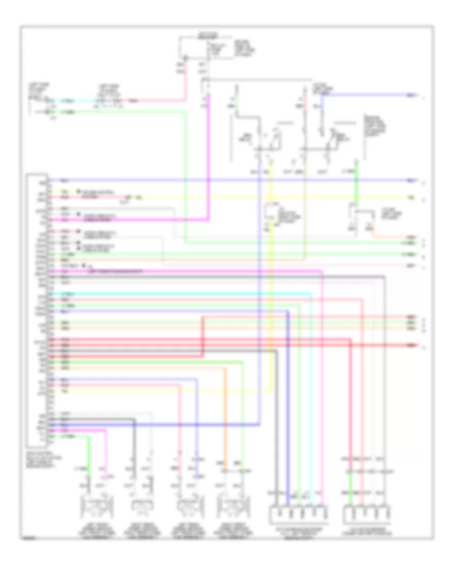
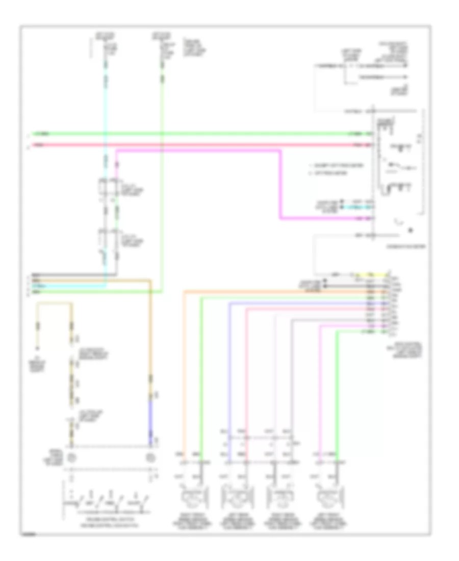
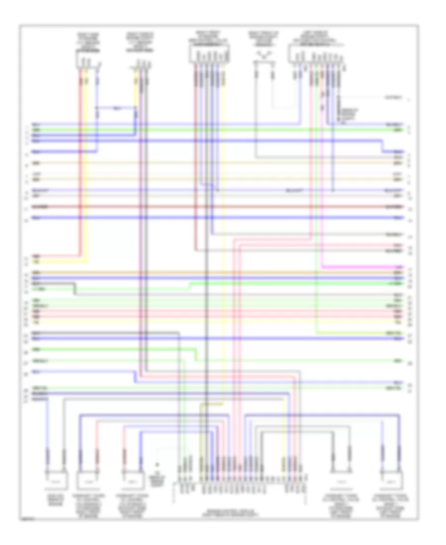
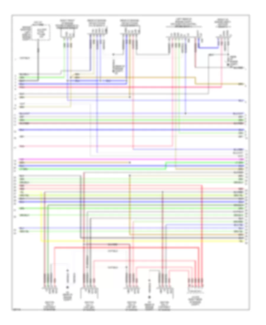
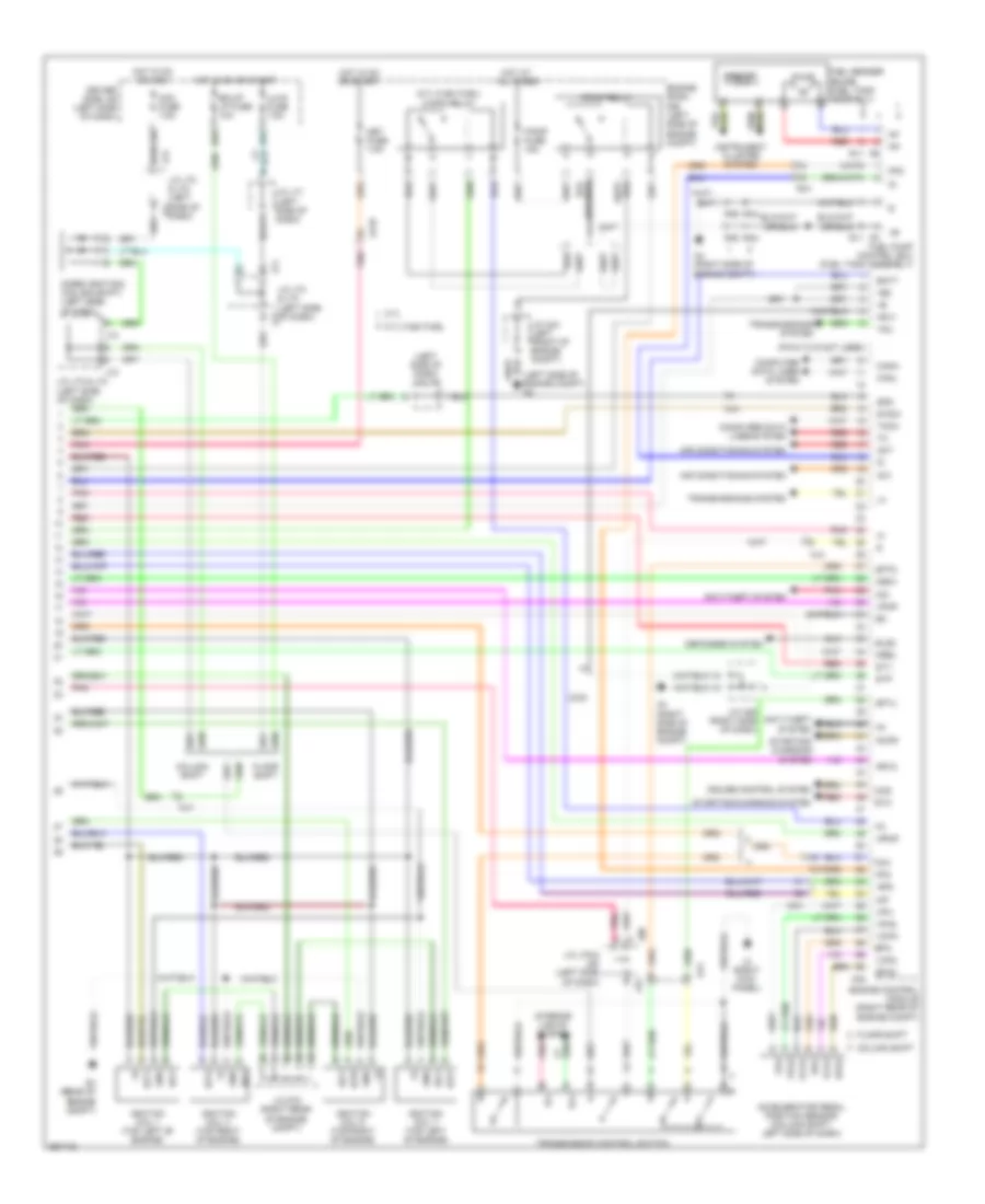
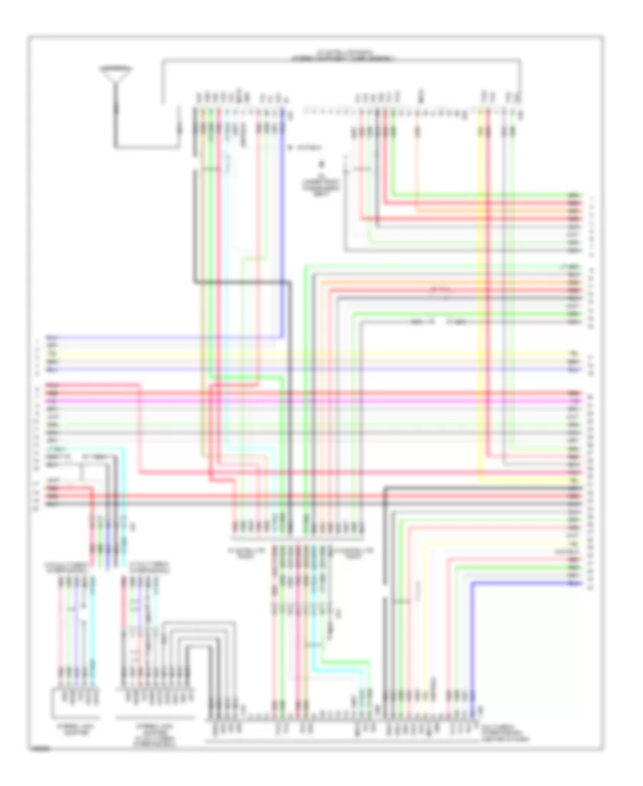
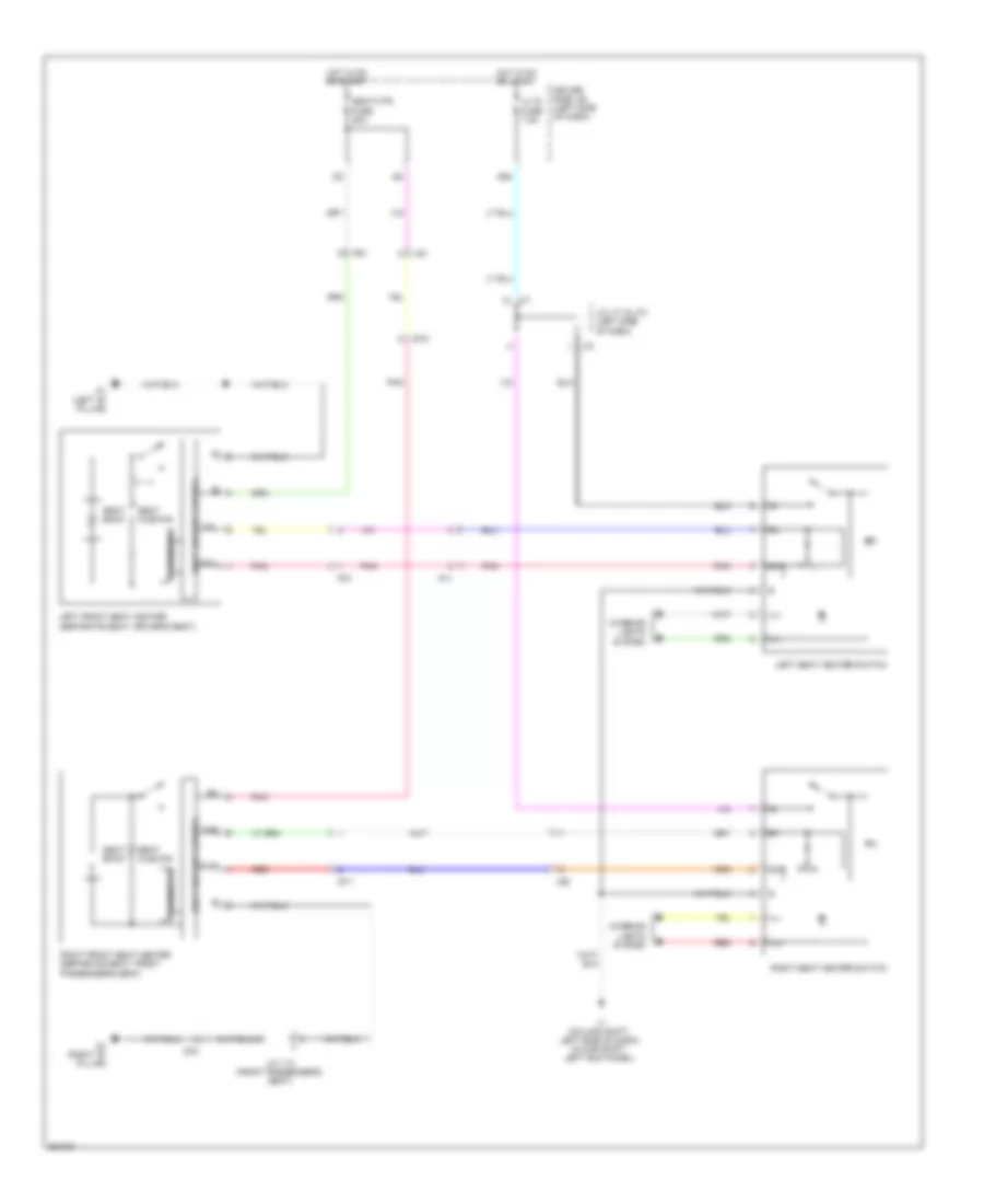
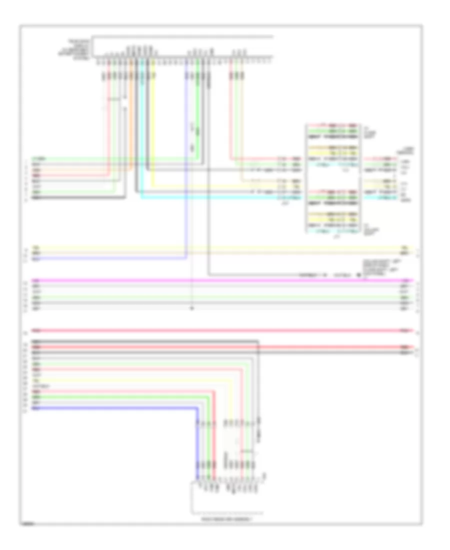
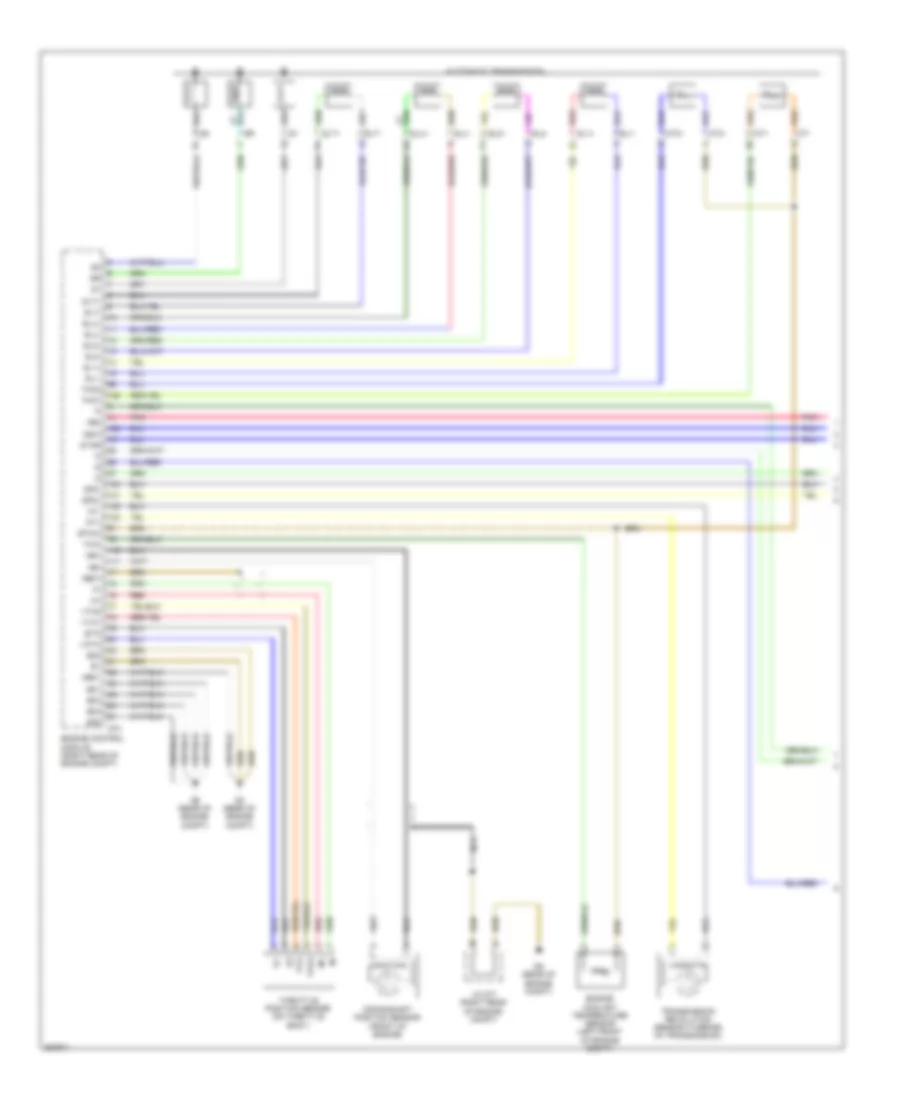
Manual A/C Wiring Diagram (2 of 2) for Toyota Tundra SR5 2012
List of elements for Manual A/C Wiring Diagram (2 of 2) for Toyota Tundra SR5 2012:
- (left side of dash) j/c a37
- 4.0l
- 4.6l
- A/c compressor (left front of engine)
- A/c pressure switch (5.7l: left front of engine)
- A2 (left side of engine compt)
- A24
- Ac1
- Act
- Aj3
- Aj7
- Ambient temperature sensor (left side of front grille)
- Blower motor (right side of dash)
- Canh
- Canl
- Computer data lines system
- D74
- Da3
- E2 ethw
- Engine control module (right rear of engine compt)
- Engine controls system
- Engine coolant temperature sensor (left front of engine compt)
- Engine room j/b (left side of engine compt)
- Except 4.0l
- Except 4.6l
- Gnd
- Hot at all times
- Htr fuse 50a
- J3 (right kick panel)
- Lock sensor
- Magnetic clutch
- Mg+
- Red
- Ssr+
- Ssr-
- Thw
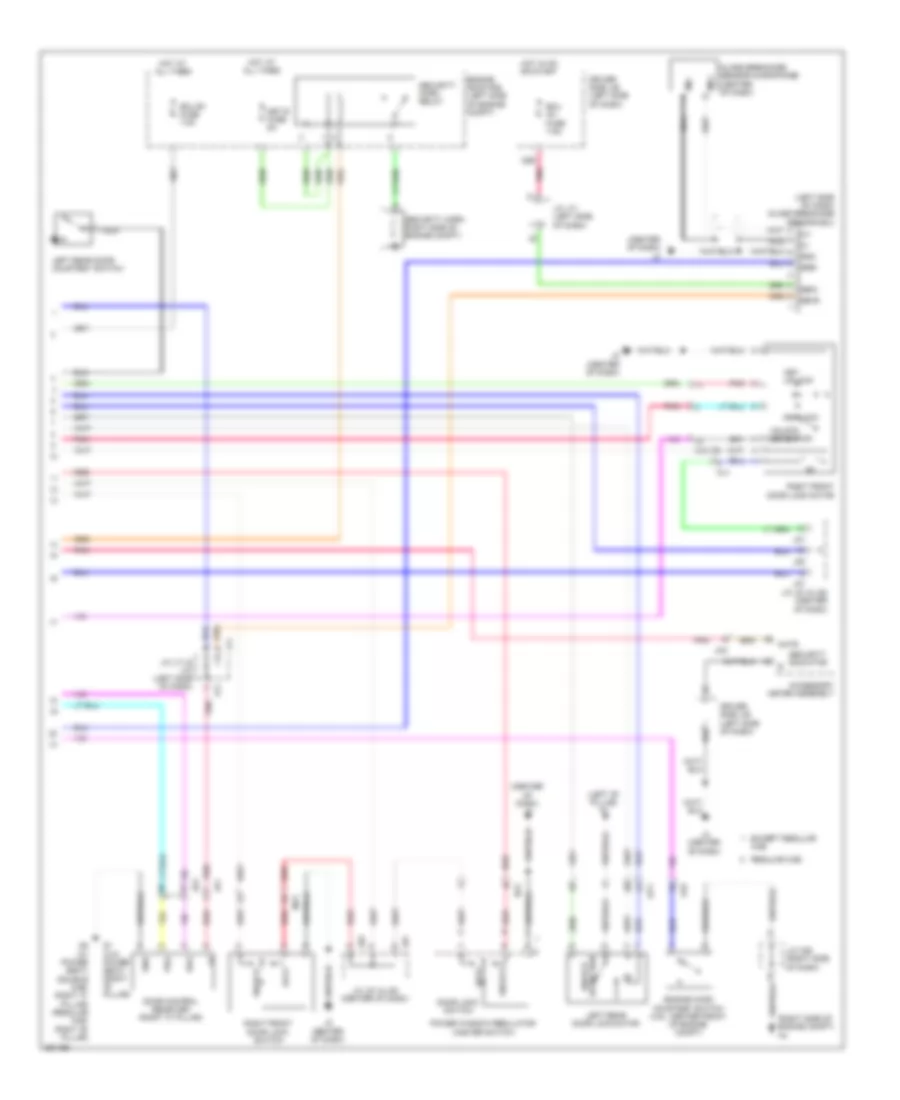
ANTI-LOCK BRAKES
Anti-lock Brakes Wiring Diagram (1 of 2) for Toyota Tundra SR5 2012
List of elements for Anti-lock Brakes Wiring Diagram (1 of 2) for Toyota Tundra SR5 2012:
- (left side of dash) j/c j71 & j72
- (left side of dash) j/c j73 & j74
- +bm
- +bs
- A2 (left side of engine compt)
- A40
- A41
- Active brake booster (5.7l: left rear of engine compt)
- Aj10
- Ap1
- Ab1
- Ab2
- B17
- Brk relay
- Bst
- Bstp
- Bsw
- Canh
- Canl
- Computer data lines system
- Cruise control system
- Csw
- D/g
- D56
- Driver side j/b (left side of dash)
- Ecu ig 1 fuse 7.5a
- Engine room r/b (left side of engine compt)
- Exi2
- Fl+
- Fl-
- Fr+
- Fr-
- Gnd1
- Gyaw
- Hot in on or start
- Ig1
- J/c a38 (left side of dash)
- J/c a40 & a41 (right side of dash)
- J/c a42 (left side of dash)
- J71
- J72
- J73
- J74
- Left front speed sensor (left front wheel hub assembly)
- Left rear speed sensor (left rear wheel hub assembly)
- Pim
- Pkb2
- Pnk
- Psnc
- Psno
- Ra1
- Red
- Right front speed sensor (right front wheel hub assembly)
- Right rear speed sensor (right rear wheel hub assembly)
- Rl+
- Rl-
- Rr+
- Rr-
- Rb1
- Skid control ecu w/ actuator (left side of engine compt)
- Sp1
- Ss1
- Ss2
- Stp
- Stp2
- Stpo
- Sts
- Vcp
- Vys
- Yaw rate sensor (under center console)
- Yaw1
- Yaw2
Anti-lock Brakes Wiring Diagram (2 of 2) for Toyota Tundra SR5 2012
List of elements for Anti-lock Brakes Wiring Diagram (2 of 2) for Toyota Tundra SR5 2012:
- (center of dash) j2
- (left front of engine compt) a1
- 4wd control ecu (right side of dash)
- A25
- A40
- A41
- Abs 1 fuse 50a
- Abs 2 fuse 40a
- Abs ind
- Add
- Add actuator (except 4.0l) (front of engine)
- Aj10
- Aj11
- Auto lsd ind
- B11
- B13
- B14
- Bat
- Brake fluid level warning switch (brake master cylinder)
- Brake ind
- Canh
- Canl
- Combination meter
- Computer data lines system
- D14
- D3 (rear of engine compt)
- Da1
- Dg1
- Driver side j/b (left side of dash)
- Ecu b1 fuse 7.5a
- Engine room r/b (left side of engine compt)
- Ess
- Hot at all times
- Hot in on or start
- Interior lights system
- J/c a40 & a41 (right side of dash)
- J/c j73 & j74 (left side of dash)
- J/c j78 (left side of dash)
- J1 (floor shift: left kick panel) (column shift: left side of dash)
- J73
- J74
- Met b fuse 5a
- Met fuse 7.5a
- Parking brake switch
- Pedal stroke speed sensor (left rear of engine compt)
- Pim
- Pnk
- Power circuit
- Red
- Slip ind
- Steering angle sensor (steering column)
- Stop fuse 15a
- Stop light switch
- Trac off ind
- Vcp
- Vsc off ind
- Vsc off switch
ANTI-THEFT
Forced Entry Wiring Diagram (1 of 2) for Toyota Tundra SR5 2012
List of elements for Forced Entry Wiring Diagram (1 of 2) for Toyota Tundra SR5 2012:
- (center of dash) j2
- (left side of dash) j/c j73 & j74
- (left side of dash) j/c j74
- (right "b" pillar) q1
- A2 (left side of engine compt)
- A24
- Acc
- Acc fuse 7.5a
- Act+
- Act-
- Actd
- Aj11
- Aj4
- Altb
- B13
- B18
- Becu
- Bk/up lp fuse 10a
- Bzr
- C23
- C24
- Canh
- Canl
- Computer data lines system
- D14
- D40
- D41
- D42
- D49
- D51
- D52
- D53
- D55
- D62
- D65
- D74
- Da1
- Dcty
- Detection unlock
- Diode (ignition) (left side of dash)
- Dr/lck fuse 25a
- Driver side j/b (left side of dash)
- Ecu ig 2 fuse 7.5a
- Engine control module (right rear of engine compt)
- Exterior lights system
- Gbs
- Gnd1
- Gnd2
- Haz
- Hcty
- Headlights system
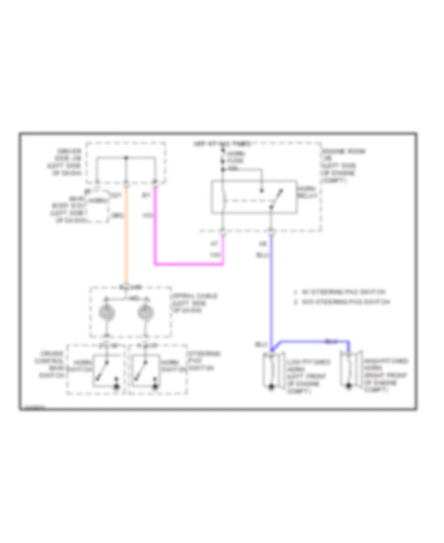
- Horn
- Horns system
- Hot at all times
- Hot in on or acc
- Hot in on or start
- Hrly
- Ile
- Ind
- Interior lights system
- J/c d73 (right rear of engine compt)
- J/c j71 & j72 (left side of dash) j72
- J/c j71 (left side of dash)
- J/c j72 (left side of dash)
- J/c j73 & j74 (left side of dash)
- J/c j75 (left side of dash)
- J1 (column shift: left side of dash) (floor shift: left kick panel)
- J2 (center of dash)
- J71
- J73
- J74
- Jq1
- Jq2
- Key lock
- Key unlock
- Ksw
- Lcty
- Left front door courtesy switch (left "b" pillar)
- Left front door lock motor
- Lh ig fuse 7.5a
- Lswd
- Lswl
- Lswp
- Lswr
- Main body ecu (left side of dash)
- Nj1
- Nj2
- Oq1
- Park/neutral position switch (transmission assembly)
- Pcty
- Pj1
- Pnk
- Prg
- Rda
- Red
- Right front door courtesy switch (right "b" pillar)
- Right rear door courtesy switch (right "c" pillar)
- Right rear door lock motor
- Rrcy
- Trly
- Ul1
- Ul2
- Ul3
- Unlock detection
- Unlock warning switch (left side of dash)
- W/ column shift
- W/ floor shift
- Wireless door lock buzzer (left front of engine compt)
Forced Entry Wiring Diagram (2 of 2) for Toyota Tundra SR5 2012
List of elements for Forced Entry Wiring Diagram (2 of 2) for Toyota Tundra SR5 2012:
- (center of dash) j2
- (left "b" pillar) p1
- (left side of dash) glass breakage sensor ecu
- (right side of engine compt) a4
- Accessory meter assembly
- Aj9
- Cab
- D56
- D62
- Door control receiver (right "c" pillar)
- Door lock switch
- Driver side j/b (left side of dash)
- Ecu b1 fuse 7.5a
- Ecu ig1 fuse 7.5a
- Engine hood courtesy switch (4.6l: center front of engine compt)
- Engine room r/b (left side of engine compt)
- Except regular
- Glass breakage sensor microphone (center of dash)
- Gnd
- Hot at all times
- Hot in on or start
- J/c a36 (right side of dash)
- J/c j71 & j72 (left side of dash)
- J/c j71 (left side of dash)
- J/c j81 & j82 (center of dash)
- J2 (center of dash)
- J71
- J72
- J81
- J82
- Jk2
- Jq1
- Jq2
- Key lock
- Key unlock
- Left rear door courtesy switch
- Left rear door lock motor
- Lock
- Met b fuse 5a
- Mhtr
- Mic+
- Mic-
- Mj1
- Mj3
- Nca
- Nca mi-
- Nj2
- Op1
- Pnk
- Power window regulator master switch
- Prg
- Q1 (w/o power seat) (right "b" pillar)
- Q2 (w/ power seat) (double cab: right "c" pillar) (regular cab: right "b" pillar)
- Rda
- Red
- Regular cab
- Right front door lock motor
- Right front door lock switch
- Security horn relay
- Security horn right side of engine compt)
- Security indicator
- Unlock
- Unlock detection
Immobilizer Wiring Diagram for Toyota Tundra SR5 2012
List of elements for Immobilizer Wiring Diagram for Toyota Tundra SR5 2012:
- (left "b" pillar) left front door courtesy switch
- (left side of dash) j/c j71 & j72
- (left side of dash) j/c j76
- A24
- Accessory meter assembly
- Agnd
- Aj2
- Aj5
- B15
- Code
- Computer data lines system
- Cty
- D17
- D62
- Driver side j/b (left side of dash)
- Efii
- Efio
- Engine control module (right rear of engine compt)
- Engine room r/b (left side of engine compt)
- Gnd
- Hot at all times
- Hot in on or start
- Ign fuse 10a
- Imb fuse 7.5a
- Imi
- Imo
- Ind
- J/c a43 (left side of dash)
- J/c j71 & j72 (left side of dash)
- J1 (column shift: left side of dash) (floor shift: left kick panel)
- J2 (center of dash)
- J3 (right kick panel)
- J71
- J72
- Jk1
- Ksw
- Pj1
- Pnk
- Security indicator
- Transponder key amplifier (column shift: at steering column) (floor shift: left side of dash)
- Transponder key coil
- Transponder key ecu (column shift: left side of dash) (floor shift: center of dash)
- Txct
- Unlock warning switch (left side of dash)
- Vc5
BODY CONTROL MODULES
Body ECU Wiring Diagram (1 of 2) for Toyota Tundra SR5 2012
List of elements for Body ECU Wiring Diagram (1 of 2) for Toyota Tundra SR5 2012:
- 7.5a
- Acc
- Acc fuse 7.5a
- Act+
- Act-
- Altb
- B11
- B13
- B16
- B18
- Becu
- C23
- C24
- Can
- Canh
- Canl
- Cann
- Canp
- Cglp
- Cgnd
- Cgsw
- Cltb
- Clte
- Clts
- D13
- D14
- D40
- D41
- D42
- D49
- D51
- D52
- D53
- D62
- Dim
- Door locks & anti-theft systems
- Dr/lck fuse 25a
- Driver side j/b (left side of dash)
- Drl
- Ecu b1
- Ecu-ig 2 fuse 7.5a
- Engine room r/b (left side of engine compt)
- Exterior lights & interior lights systems
- Exterior lights system
- Ffog
- Fuse
- Gnd1
- Gnd2
- Haz
- Head
- Headlights system
- Headlights, anti-lock brakes & instrument cluster systems
- Horn
- Horns system
- Hot at all times
- Hot in on or acc
- Hot in on or start
- Hrly
- Ile
- Interior lights system
- J/c j114 (w/ seat position memory) (left side of dash)
- J1 (column shift: left side of dash) (floor shift: left kick panel)
- Lcty
- Left front power seat control ecu & switch (driver's seat)
- Lin2
- Lswl
- Lswp
- Lswr
- Main body ecu (left side of dash)
- Memory systems
- Multiplex tilt & telescopic ecu (floor shift: left side of dash)
- Nj3
- Outer mirror control ecu (driver's door)
- P/w relay
- Pcty
- Pj1
- Pkb
- Pnk
- Power tops & power windows systems
- Prg
- Pws
- Pz1
- Rda
- Red
- Ret
- Rrcy
- Trly
- Ul1
- Ul2
- Z10
Body ECU Wiring Diagram (2 of 2) for Toyota Tundra SR5 2012
List of elements for Body ECU Wiring Diagram (2 of 2) for Toyota Tundra SR5 2012:
- (left side of dash)
- 4wd control ecu (4wd) (right side of dash)
- A/c amplifier (center of dash)
- A24
- A25
- Actd
- Aj11
- Aj3
- Aj5
- Bus buffer (right side of dash)
- Bzr
- Can+
- Can-
- Canh
- Canl
- Center air bag ecu (column shift: center of dash) (floor shift: under center console)
- Combination meter
- Dcty
- Dlc 3 (left side of dash)
- Door locks & anti-theft systems
- Engine control module (right rear of engine compt)
- Exterior lights & headlights systems
- Ffgo
- Gbs
- Hcty
- Headlights system
- Ind
- Interior lights system
- J/c j113 (center of dash)
- J/c j118 (left side of dash)
- J19
- J46
- Ksw
- Lswd
- Main body ecu
- Memory systems
- Mirb
- Mire
- Mirs
- Pnk
- Power steering ecu assembly (4.6l) (left side of dash)
- Red
- Skid control ecu w/ actuator (left side of engine compt)
- Steering angle sensor (steering column)
- Tail
- Ul3
- Warning systems
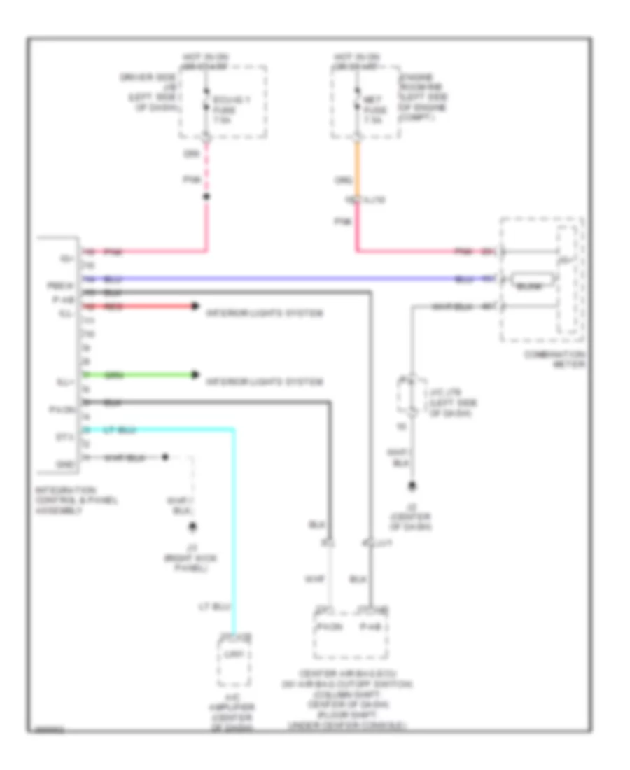
Integration Control and Panel Wiring Diagram for Toyota Tundra SR5 2012
List of elements for Integration Control and Panel Wiring Diagram for Toyota Tundra SR5 2012:
- A/c amplifier (center of dash)
- Aj10
- Blink
- Center air bag ecu (w/ air bag cutoff switch) (column shift: center of dash) (floor shift: under center console)
- Combination meter
- D56
- Driver side j/b (left side of dash)
- Ecu-ig 1 fuse 7.5a
- Engine room r/b (left side of engine compt)
- Gnd
- Hot in on or start
- Ig+
- Ill+
- Ill-
- Integration control & panel assembly
- Interior lights system
- J/c j78 (left side of dash)
- J19
- J2 (center of dash)
- J3 (right kick panel)
- J46
- Jj1
- Lin1
- Met fuse 7.5a
- P-ab
- Paon
- Pbew
- Pnk
- Red
- Stx
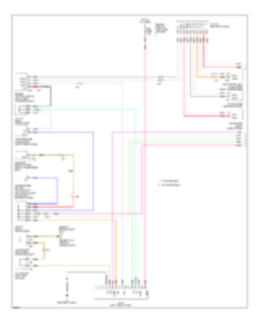
COMPUTER DATA LINES
Computer Data Lines Wiring Diagram (1 of 2) for Toyota Tundra SR5 2012
List of elements for Computer Data Lines Wiring Diagram (1 of 2) for Toyota Tundra SR5 2012:
- (rear of engine compt) (4.0l)
- 4wd control ecu (if equipped) (right side of dash)
- A/c amplifier (center of dash)
- A24
- A25
- A45
- Aj11
- Aj2
- Aj3
- Aj4
- Aj5
- Bat
- Bus buffer (right side of dash)
- Can+
- Can-
- Canh
- Canl
- D1 (except 4.0l) (rear of engine compt)
- D18
- D73
- Dia
- Dlc3 (left side of dash)
- Driver side j/b (left side of dash)
- Engine control module (right rear of engine compt)
- Hot at all times
- J/c a45 & d73 (right rear of engine compt)
- J/c j113 (center of dash)
- J/c j117 (right side of dash)
- J/c j79 & j80 (left side of dash)
- J19
- J2 (center of dash)
- J79
- J80
- Jq2
- Obd fuse 7.5a
- Occupant detection ecu (front passenger's seat)
- Pnk
- Q11
- Qy1
- Red
- Sil
- Tac
- Tach
- Tire pressure warning ecu (right side of dash)
- Transponder key ecu (column shift: left side of dash) (floor shift: center of dash)
- W/ power seat
- W/o power seat
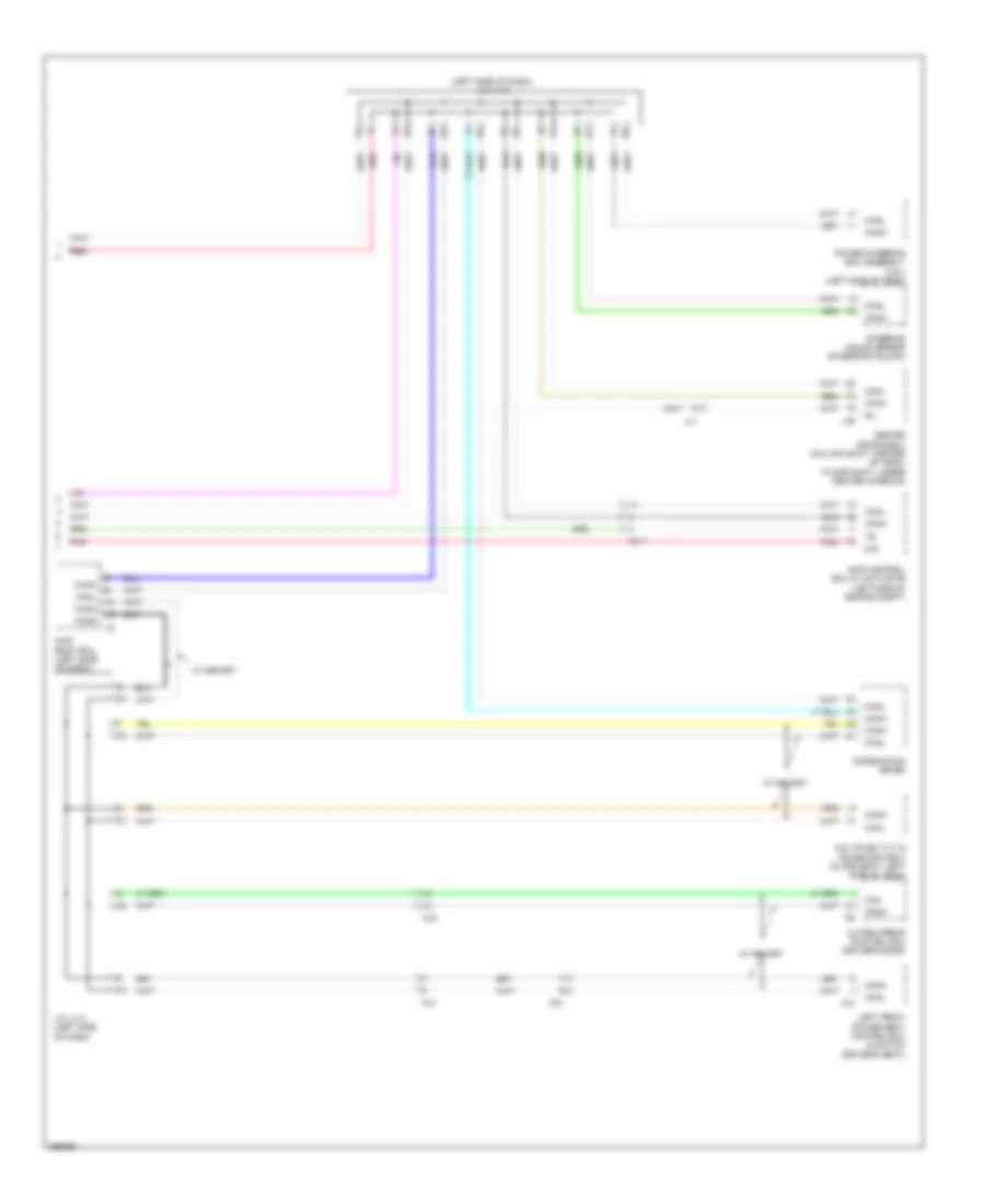
Computer Data Lines Wiring Diagram (2 of 2) for Toyota Tundra SR5 2012
List of elements for Computer Data Lines Wiring Diagram (2 of 2) for Toyota Tundra SR5 2012:
- (left side of dash) j/c j118
- Aj11
- Can
- Canh
- Canl
- Cann
- Canp
- Center air bag ecu (column shift: center of dash) (floor shift: under center console)
- Cgnd
- Combination meter
- D/g
- J/c j114 (left side of dash)
- J46
- Jj1
- Left front power seat control ecu & switch (driver's seat)
- Main body ecu (left side of dash)
- Multiplex tilt & telescopic ecu (floor shift: left side of dash)
- Nj3
- Outer mirror control ecu (driver's door)
- Pj1
- Pnk
- Power steering ecu assembly (4.6l) (left side of dash)
- Pz1
- Red
- Sil
- Skid control ecu w/ actuator (left side of engine compt)
- Steering angle sensor (steering column)
- W/ memory
- Z10
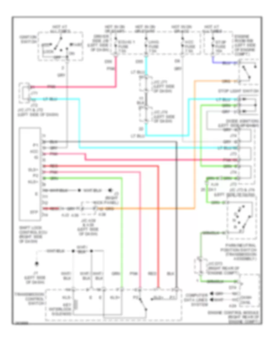
CRUISE CONTROL
4.0L
4.0L, Cruise Control Wiring Diagram (1 of 2) for Toyota Tundra SR5 2012
List of elements for 4.0L, Cruise Control Wiring Diagram (1 of 2) for Toyota Tundra SR5 2012:
- (left side of dash) j/c a38 & a39
- (right side of engine compt)
- +b2
- +bm
- A2 (left side of engine compt)
- A24
- A38
- A39
- A42
- A43
- Accelerator pedal position sensor (column shift: left side of dash)
- Aj10
- Aj4
- Batt
- Canh
- Canl
- Ccs
- Column shift
- Computer data lines system
- D74
- D8 (rear of engine compt)
- D9 (rear of engine compt)
- Da1
- Da2
- Diode (ignition) (left side of dash)
- E01
- E02
- E03
- Efi 1 fuse 25a
- Efi relay
- Engine control module (right rear of engine compt)
- Engine controls system
- Engine room j/b (left side of engine compt)
- Engine room r/b (left side of engine compt)
- Epa
- Epa2
- Eta
- Etcs fuse 10a
- Floor shift
- Ge01
- Hot at all times
- Hot in on or start
- Ign fuse 10a
- Igsw
- J/c a36 (right side of dash)
- J/c a42 & a43 (left side of dash)
- J/c a44 (left front of engine compt)
- J/c d73 (right rear of engine compt)
- J/c j73 & j74 (left side of dash)
- J73
- J74
- Me01
- Met b fuse 5a
- Met fuse 7.5a
- Mrel
- Park/neutral position switch (transmission assembly)
- Pnk
- Red
- Spd
- St1-
- Stop fuse 15a
- Stop light switch
- Stp
- Throttle position sensor (on throttle body)
- Vcp2
- Vcpa
- Vcta
- Vpa
- Vpa2
- Vta
- Vta1
- Vta2
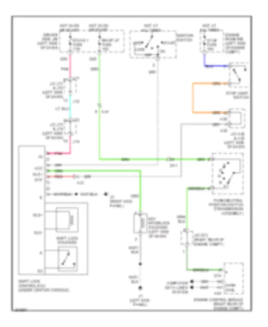
4.0L, Cruise Control Wiring Diagram (2 of 2) for Toyota Tundra SR5 2012
List of elements for 4.0L, Cruise Control Wiring Diagram (2 of 2) for Toyota Tundra SR5 2012:
- (column shift: left side of dash) (floor shift: left kick panel) j1
- (left side of dash) j/c j78
- +res
- -set
- A45
- Aj11
- Aj3
- Aj5
- Ab1
- Ab2
- Bk/up lp fuse 10a
- Cancel
- Canh
- Canl
- Combination meter
- Computer data lines system
- Cruise control main switch
- Cruise control switch
- Cruise ind
- D55
- D65
- D73
- D8 (rear of engine compt)
- Driver side j/b (left side of dash)
- Fl+
- Fl-
- Fr+
- Fr-
- Hot in on or start
- J/c a45 & d73 (right rear of engine compt)
- J/c j71 (left side of dash)
- J/c j74 (left side of dash)
- J/c j79 & j80 (left side of dash)
- J2 (center of dash)
- J45
- J79
- J80
- Left front speed sensor (left front wheel hub assembly)
- Left rear speed sensor (left rear wheel hub assembly)
- Lh ig fuse 7.5a
- On-off
- Pnk
- Power circuit
- Ra1
- Red
- Right front speed sensor (right front wheel hub assembly)
- Right rear speed sensor (right rear wheel hub assembly)
- Rl+
- Rl-
- Rr+
- Rr-
- Rb1
- Skid control ecu w/ actuator (left side of engine compt)
- Sp1
- Spiral cable (left side of dash)
4.6L
4.6L, Cruise Control Wiring Diagram (1 of 2) for Toyota Tundra SR5 2012
List of elements for 4.6L, Cruise Control Wiring Diagram (1 of 2) for Toyota Tundra SR5 2012:
- (left front of engine compt) j/c a44
- (left side of dash) j/c a38 & a39
- (right side of engine compt) a4
- +b2
- +bm
- A2 (left side of engine compt)
- A24
- A38
- A39
- A42
- A43
- Accelerator pedal position sensor (column shift: left side of dash)
- Aj10
- Aj4
- Batt
- Canh
- Canl
- Ccs
- Column shift
- Computer data lines system
- D1 (rear of engine compt)
- D2 (rear of engine compt)
- D74
- Da1
- Da2
- Diode (ignition) (left side of dash)
- E03
- Efi 1 fuse 25a
- Efi relay
- Engine control module (right rear of engine compt)
- Engine controls system
- Engine room j/b (left side of engine compt)
- Engine room r/b (left side of engine compt)
- Epa
- Epa2
- Eta
- Etcs fuse 10a
- Floor shift
- Ge01
- Hot at all times
- Hot in on or start
- Ign fuse 10a
- Igsw
- J/c a36 (right side of dash)
- J/c a42 & a43 (left side of dash)
- J/c d73 (right rear of engine compt)
- J/c j73 & j74 (left side of dash)
- J73
- J74
- Me01
- Met b fuse 5a
- Met fuse 7.5a
- Mrel
- Park/neutral position switch (transmission assembly)
- Pnk
- Red
- Spd
- St1-
- Stop fuse 15a
- Stop light switch
- Stp
- Throttle position sensor (on throttle body)
- Vcp2
- Vcpa
- Vcta
- Vpa
- Vpa2
- Vta1
- Vta2
4.6L, Cruise Control Wiring Diagram (2 of 2) for Toyota Tundra SR5 2012
List of elements for 4.6L, Cruise Control Wiring Diagram (2 of 2) for Toyota Tundra SR5 2012:
- (column shift: left side of dash) (floor shift: left kick panel) j1
- (left side of dash) j/c j78
- +res
- -set
- A45
- Aj11
- Aj3
- Aj5
- Ab1
- Ab2
- Bk/up lp fuse 10a
- Cancel
- Canh
- Canl
- Combination meter
- Computer data lines system
- Cruise control main switch
- Cruise control switch
- Cruise ind
- D1 (rear of engine compt)
- D55
- D65
- D73
- Dim
- Driver side j/b (left side of dash)
- Except optitron meter
- Fl+
- Fl-
- Fr+
- Fr-
- Hot in on or start
- J/c a45 & d73 (right rear of engine compt)
- J/c j71 (left side of dash)
- J/c j74 (left side of dash)
- J/c j79 & j80 (left side of dash)
- J2 (center of dash)
- J45
- J79
- J80
- Left front speed sensor (left front wheel hub assembly)
- Left rear speed sensor (left rear wheel hub assembly)
- Lh ig fuse 7.5a
- On-off
- Optitron meter
- Pnk
- Power circuit
- Ra1
- Red
- Right front speed sensor (right front wheel hub assembly)
- Right rear speed sensor (right rear wheel hub assembly)
- Rl+
- Rl-
- Rr+
- Rr-
- Rb1
- Skid control ecu w/ actuator (left side of engine compt)
- Sp1
- Spiral cable (left side of dash)
5.7L
5.7L, Cruise Control Wiring Diagram (1 of 2) for Toyota Tundra SR5 2012
List of elements for 5.7L, Cruise Control Wiring Diagram (1 of 2) for Toyota Tundra SR5 2012:
- (left front of engine compt) j/c a44
- (left side of dash) j/c a38 & a39
- (right side of engine compt) a4
- +b2
- +bm
- A2 (left side of engine compt)
- A24
- A38
- A39
- A42
- A43
- Accelerator pedal position sensor (column shift: left side of dash)
- Aj10
- Aj4
- Batt
- Canh
- Canl
- Ccs
- Column shift
- Computer data lines system
- D1 (rear of engine compt)
- D2 (rear of engine compt)
- D74
- Da1
- Da2
- Diode (ignition) (left side of dash)
- E01
- E02
- E03
- E04
- E05
- Efi 1 fuse 25a
- Efi relay
- Engine control module (right rear of engine compt)
- Engine controls system
- Engine room j/b (left side of engine compt)
- Engine room r/b (left side of engine compt)
- Epa
- Epa2
- Eta
- Etcs fuse 10a
- Floor shift
- Ge01
- Hot at all times
- Hot in on or start
- Ign fuse 10a
- Igsw
- J/c a36 (right side of dash)
- J/c a42 & a43 (left side of dash)
- J/c d73 (right rear of engine compt)
- J/c j73 & j74 (left side of dash)
- J73
- J74
- Me01
- Met fuse 7.5a
- Met-b fuse 5a
- Mrel
- Park/neutral position switch (transmission assembly)
- Pnk
- Red
- Spd
- St1-
- Stop fuse 15a
- Stop light switch
- Stp
- Throttle position sensor (on throttle body)
- Vcp2
- Vcpa
- Vcta
- Vpa
- Vpa2
- Vta1
- Vta2
5.7L, Cruise Control Wiring Diagram (2 of 2) for Toyota Tundra SR5 2012
List of elements for 5.7L, Cruise Control Wiring Diagram (2 of 2) for Toyota Tundra SR5 2012:
- (column shift: left side of dash) (floor shift: left kick panel) j1
- (left side of dash) j/c j78
- +res
- -set
- A45
- Aj11
- Aj3
- Aj5
- Ab1
- Ab2
- Bk/up lp fuse 10a
- Cancel
- Canh
- Canl
- Combination meter
- Computer data lines system
- Cruise control main switch
- Cruise control switch
- Cruise ind
- D1 (rear of engine compt)
- D55
- D65
- D73
- Dim
- Driver side j/b (left side of dash)
- Except optitron meter
- Fl+
- Fl-
- Fr+
- Fr-
- Hot in on or start
- J/c a45 & d73 (right rear of engine compt)
- J/c j71 (left side of dash)
- J/c j74 (left side of dash)
- J/c j79 & j80 (left side of dash)
- J2 (center of dash)
- J45
- J79
- J80
- Left front speed sensor (left front wheel hub assembly)
- Left rear speed sensor (left rear wheel hub assembly)
- Lh ig fuse 7.5a
- On-off
- Optitron meter
- Pnk
- Power circuit
- Ra1
- Red
- Right front speed sensor (right front wheel hub assembly)
- Right rear speed sensor (right rear wheel hub assembly)
- Rl+
- Rl-
- Rr+
- Rr-
- Rb1
- Skid control ecu w/ actuator (left side of engine compt)
- Sp1
- Spiral cable (left side of dash)
5.7L FLEX FUEL
5.7L Flex Fuel, Cruise Control Wiring Diagram (1 of 2) for Toyota Tundra SR5 2012
List of elements for 5.7L Flex Fuel, Cruise Control Wiring Diagram (1 of 2) for Toyota Tundra SR5 2012:
- (left front of engine compt) j/c a44
- (left side of dash) j/c a38 & a39
- (right side of engine compt) a4
- +b2
- +bm
- A2 (left side of engine compt)
- A24
- A38
- A39
- A42
- A43
- Accelerator pedal position sensor (column shift: left side of dash)
- Aj10
- Aj4
- Batt
- Canh
- Canl
- Ccs
- Column shift
- Computer data lines system
- D1 (rear of engine compt)
- D2 (rear of engine compt)
- D74
- Da1
- Da2
- Diode (ignition) (left side of dash)
- E01
- E02
- E03
- E04
- E05
- Efi 1 fuse 25a
- Efi relay
- Engine control module (right rear of engine compt)
- Engine controls system
- Engine room j/b (left side of engine compt)
- Engine room r/b (left side of engine compt)
- Epa
- Epa2
- Eta
- Etcs fuse 10a
- Floor shift
- Ge01
- Hot at all times
- Hot in on or start
- Ign fuse 10a
- Igsw
- J/c a36 (right side of dash)
- J/c a42 & a43 (left side of dash)
- J/c d73 (right rear of engine compt)
- J/c j73 & j74 (left side of dash)
- J73
- J74
- Me01
- Met fuse 7.5a
- Met-b fuse 5a
- Mrel
- Park/neutral position switch (transmission assembly)
- Pnk
- Red
- Spd
- St1-
- Stop fuse 15a
- Stop light switch
- Stp
- Throttle position sensor (on throttle body)
- Vcp2
- Vcpa
- Vcta
- Vpa
- Vpa2
- Vta1
- Vta2
5.7L Flex Fuel, Cruise Control Wiring Diagram (2 of 2) for Toyota Tundra SR5 2012
List of elements for 5.7L Flex Fuel, Cruise Control Wiring Diagram (2 of 2) for Toyota Tundra SR5 2012:
- (column shift: left side of dash) (floor shift: left kick panel) j1
- (left side of dash) j/c j78
- +res
- -set
- A45
- Aj11
- Aj3
- Aj5
- Ab1
- Ab2
- Bk/up lp fuse 10a
- Cancel
- Canh
- Canl
- Combination meter
- Computer data lines system
- Cruise control main switch
- Cruise control switch
- Cruise ind
- D1 (rear of engine compt)
- D55
- D65
- D73
- Dim
- Driver side j/b (left side of dash)
- Except optitron meter
- Fl+
- Fl-
- Fr+
- Fr-
- Hot in on or start
- J/c a45 & d73 (right rear of engine compt)
- J/c j71 (left side of dash)
- J/c j74 (left side of dash)
- J/c j79 & j80 (left side of dash)
- J2 (center of dash)
- J45
- J79
- J80
- Left front speed sensor (left front wheel hub assembly)
- Left rear speed sensor (left rear wheel hub assembly)
- Lh ig fuse 7.5a
- On-off
- Optitron meter
- Pnk
- Power circuit
- Ra1
- Red
- Right front speed sensor (right front wheel hub assembly)
- Right rear speed sensor (right rear wheel hub assembly)
- Rl+
- Rl-
- Rr+
- Rr-
- Rb1
- Skid control ecu w/ actuator (left side of engine compt)
- Sp1
- Spiral cable (left side of dash)
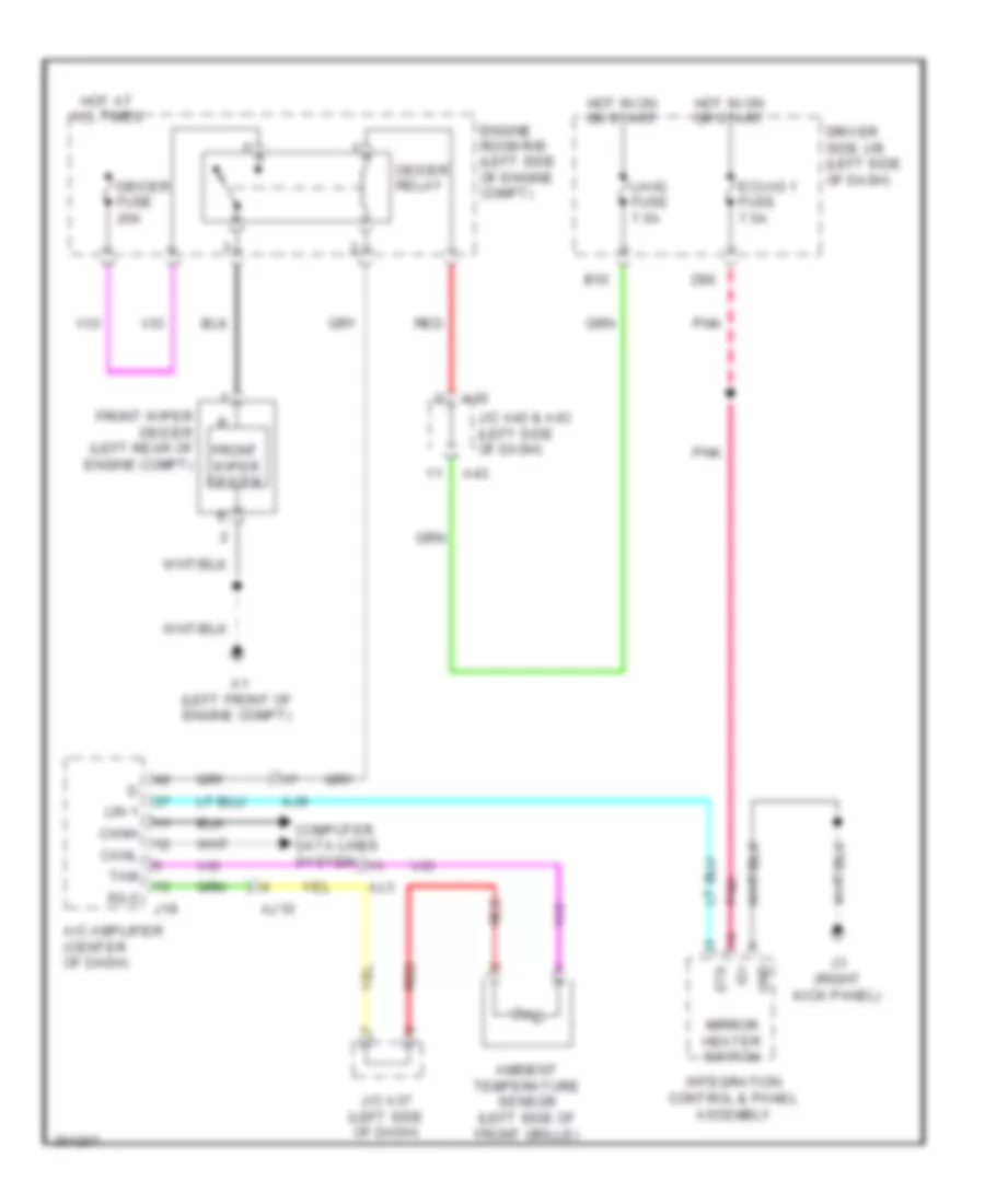
DEFOGGERS
Front Deicer Wiring Diagram for Toyota Tundra SR5 2012
List of elements for Front Deicer Wiring Diagram for Toyota Tundra SR5 2012:
- A/c amplifier (center of dash)
- A1 (left front of engine compt)
- A42
- A43
- Aj10
- Aj3
- Aj9
- Ambient temperature sensor (left side of front grille)
- B10
- Canh
- Canl
- Computer data lines system
- D56
- Deicer fuse 20a
- Deicer relay
- Driver side j/b (left side of dash)
- Ecu-ig 1 fuse 7.5a
- Engine room r/b (left side of engine compt)
- Front wiper deicer
- Front wiper deicer (left rear of engine compt)
- Gnd
- Hot at all times
- Hot in on or start
- Ig+
- Integration control & panel assembly
- J/c a37 (left side of dash)
- J/c a42 & a43 (left side of dash)
- J19
- J3 (right kick panel)
- Lh-ig fuse 7.5a
- Lin 1
- Mirror heater switch
- Pnk
- Red
- Sg-2
- Stx
- Tam
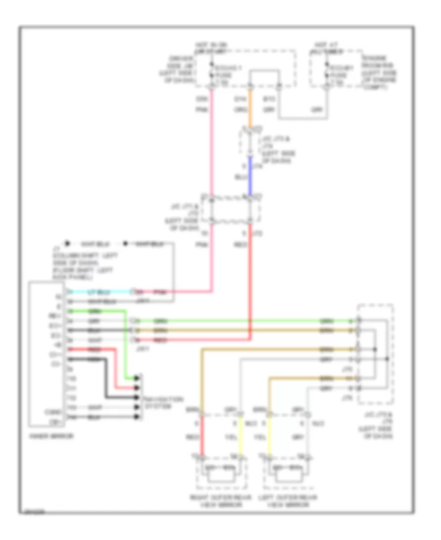
Heated Mirrors Wiring Diagram for Toyota Tundra SR5 2012
List of elements for Heated Mirrors Wiring Diagram for Toyota Tundra SR5 2012:
- (right kick panel) j3
- A/c amplifier (center of dash)
- Aj10
- Aj3
- Ambient temperature sensor (left side of front grille)
- Canh
- Canl
- Computer data lines system
- D11
- D19
- D38
- D50
- D55
- D56
- Driver side j/b (left side of dash)
- Ecu-ig 1 fuse 7.5a
- Gnd
- Heater switch
- Hot at all times
- Hot in on or start
- Ig+
- Integration control & panel assembly
- J/c a37 (left side of dash)
- J/c j71 (left side of dash)
- J/c j73 & j74 (left side of dash)
- J19
- J2 (center of dash)
- J73
- J74
- Left outer rear view mirror
- Lh-ig fuse 7.5a
- Lin 1
- Mhtr
- Mir fuse 15a
- Mir htr relay
- Mirror
- Mirror heater
- Mj3
- Nj2
- Pnk
- Red
- Right outer rear view mirror
- Sg-2
- Stx
- Tam
Rear Defogger Wiring Diagram for Toyota Tundra SR5 2012
List of elements for Rear Defogger Wiring Diagram for Toyota Tundra SR5 2012:
- A/c amplifier (center of dash)
- A2 (5.7l: left side of engine compt) (except 5.7l: left front of engine compt)
- A24
- Aj10
- Aj3
- Ambient temperature sensor (left side of front grille)
- Ap2
- B10
- Can h
- Can l
- Canh
- Canl
- Computer data lines system
- D56
- Def i/up fuse 5a
- Defog fuse 40a
- Defog relay
- Driver side j/b (left side of dash)
- Ecu-ig 1 fuse 7.5a
- Els2
- Engine control module (right rear of engine compt)
- Engine room r/b (left side of engine compt)
- Gnd
- Hot at all times
- Hot in on or start
- Ig+
- Integration control & panel assembly
- J/c a37 (left side of dash)
- J/c a43 (left side of dash)
- J/c a44 (left front of engine compt)
- J19
- J3 (right kick panel)
- Lh-ig fuse 7.5a
- Lin1
- Noise filter
- P10
- P2 (regular cab: left "b" pillar)
- Pnk
- Rdef
- Rear window defogger
- Rear window defogger switch
- Red
- Sg-2
- Stx
- Tam
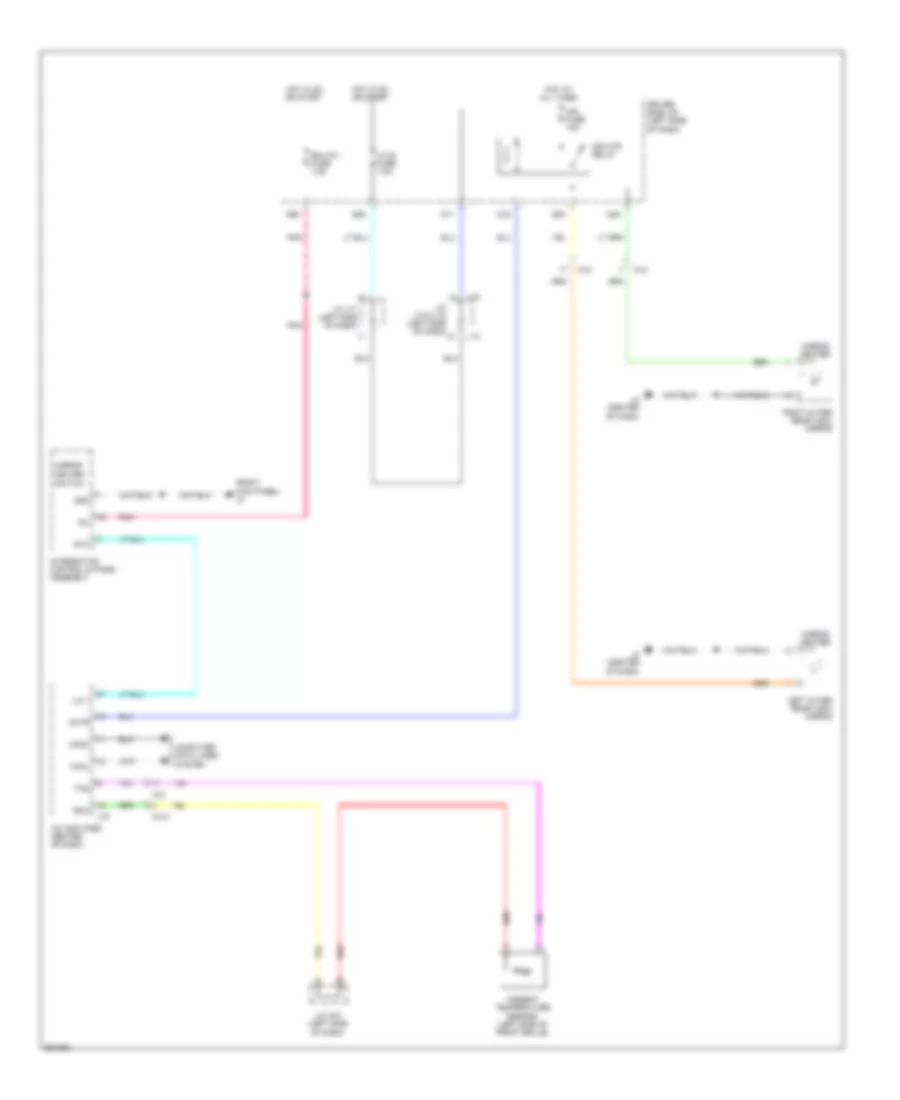
ELECTRONIC POWER STEERING
Electronic Power Steering Wiring Diagram for Toyota Tundra SR5 2012
List of elements for Electronic Power Steering Wiring Diagram for Toyota Tundra SR5 2012:
- Aj10
- Aj3
- B13
- Bat
- Canh
- Canl
- Combination meter assembly
- Computer data lines system
- D14
- D56
- Da1
- Driver side j/b (left side of dash)
- Ecu b1 fuse 7.5a
- Ecu-ig 1 fuse 7.5a
- Ecu-ig 2 fuse 7.5a
- Engine room r/b (left side of engine compt)
- Ess
- Gnd
- H71
- H73
- Hot at all times
- Hot in on or start
- J/c j71 & j72 (left side of dash)
- J/c j73 & j74 (left side of dash)
- J/c j78 (left side of dash)
- J1 (column shift: left side of dash) (floor shift: left kick panel)
- J2 (center of dash)
- J3 (right kick panel)
- J72
- J74
- Met fuse 7.5a
- Met-b fuse 5a
- Pnk
- Power circuit
- Power steering ecu assembly (left side of dash)
- Power steering ind
- Red
- Sof+
- Sof-
- Steering angle sensor (steering column)
- Vane pump assembly
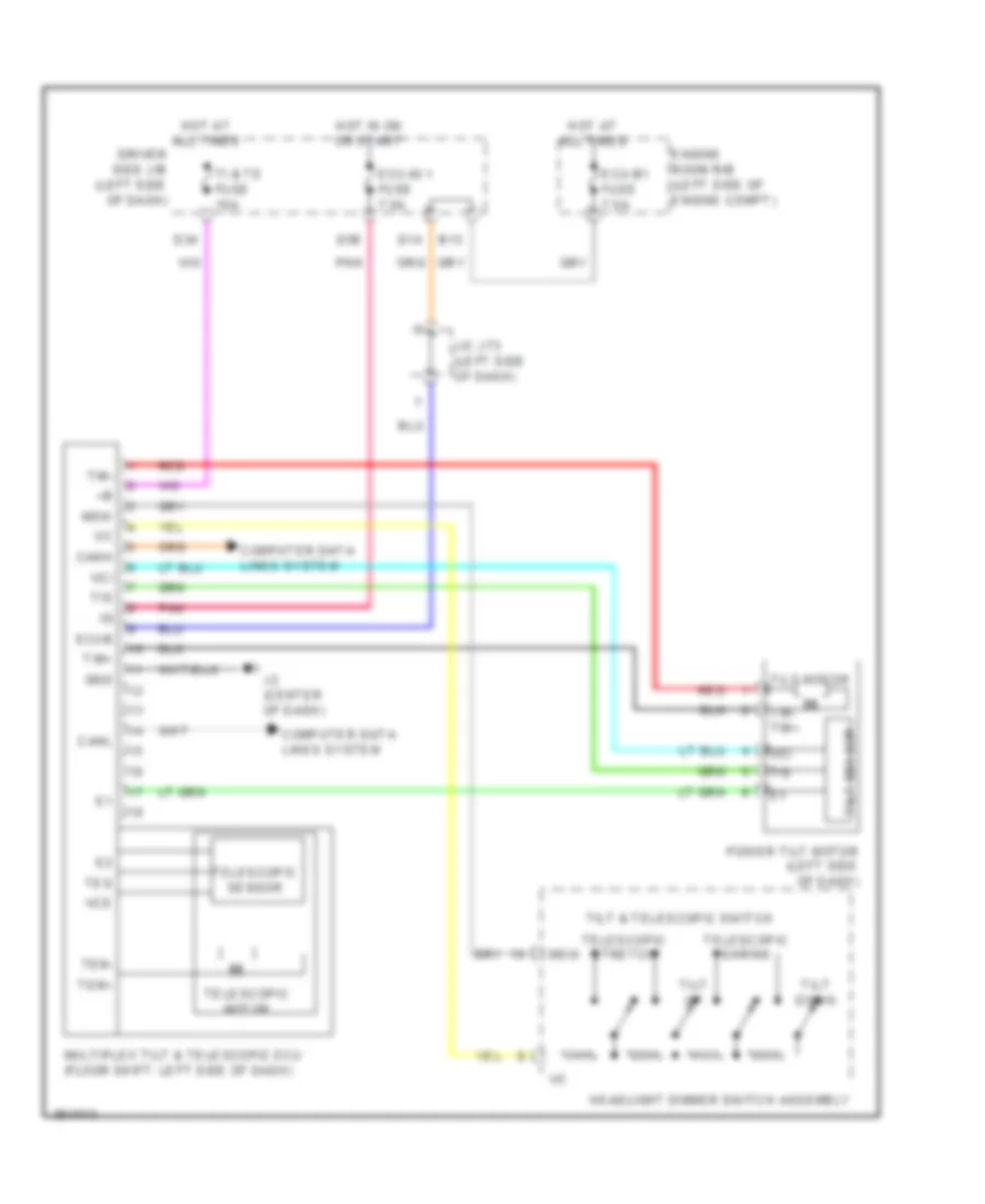
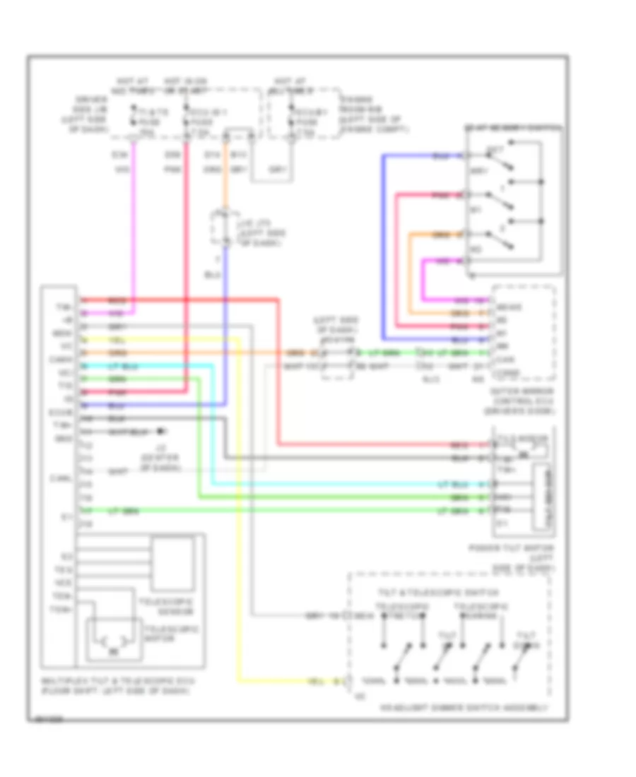
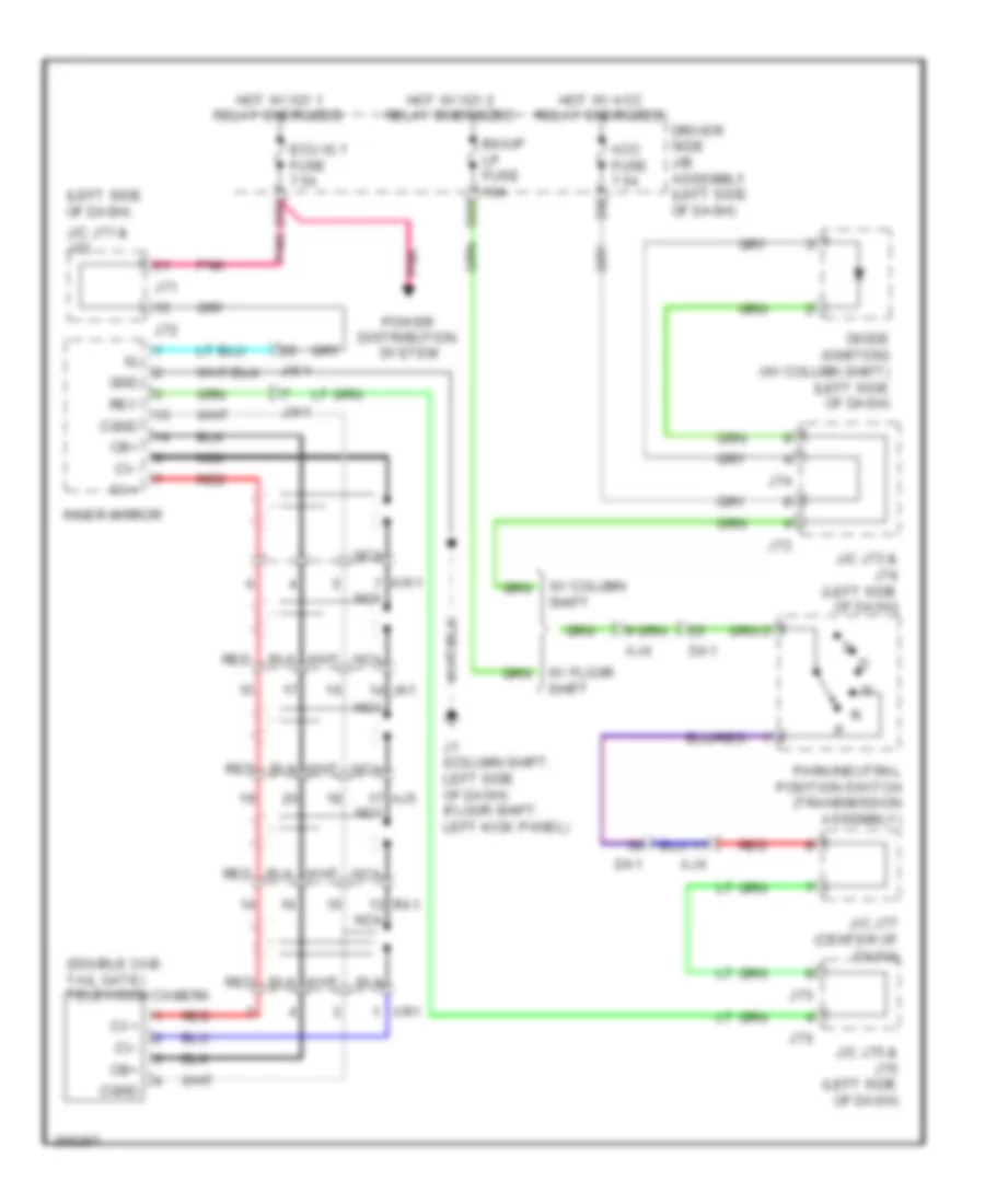
Power Tilt Steering Column Wiring Diagram for Toyota Tundra SR5 2012
List of elements for Power Tilt Steering Column Wiring Diagram for Toyota Tundra SR5 2012:
- B13
- Canh
- Canl
- Computer data lines system
- D14
- D34
- D56
- Driver side j/b (left side of dash)
- Ecu-b1 fuse 7.5a
- Ecu-ig 1 fuse 7.5a
- Ecub
- Engine room r/b (left side of engine compt)
- Gnd
- Headlight dimmer switch assembly
- Hot at all times
- Hot in on or start
- J/c j73 (left side of dash)
- J2 (center of dash)
- Msw
- Multiplex tilt & telescopic ecu (floor shift: left side of dash)
- Pnk
- Power tilt motor (left side of dash)
- Red
- Telescopic motor
- Telescopic sensor
- Telescopic shrink
- Telescopic stretch
- Tem+
- Tem-
- Tes
- Ti & te fuse 15a
- Tilt & telescopic switch
- Tilt down
- Tilt motor
- Tilt sensor
- Tilt up
- Tim+
- Tim-
- Tim- tim+
- Tis
- Vce
- Vci
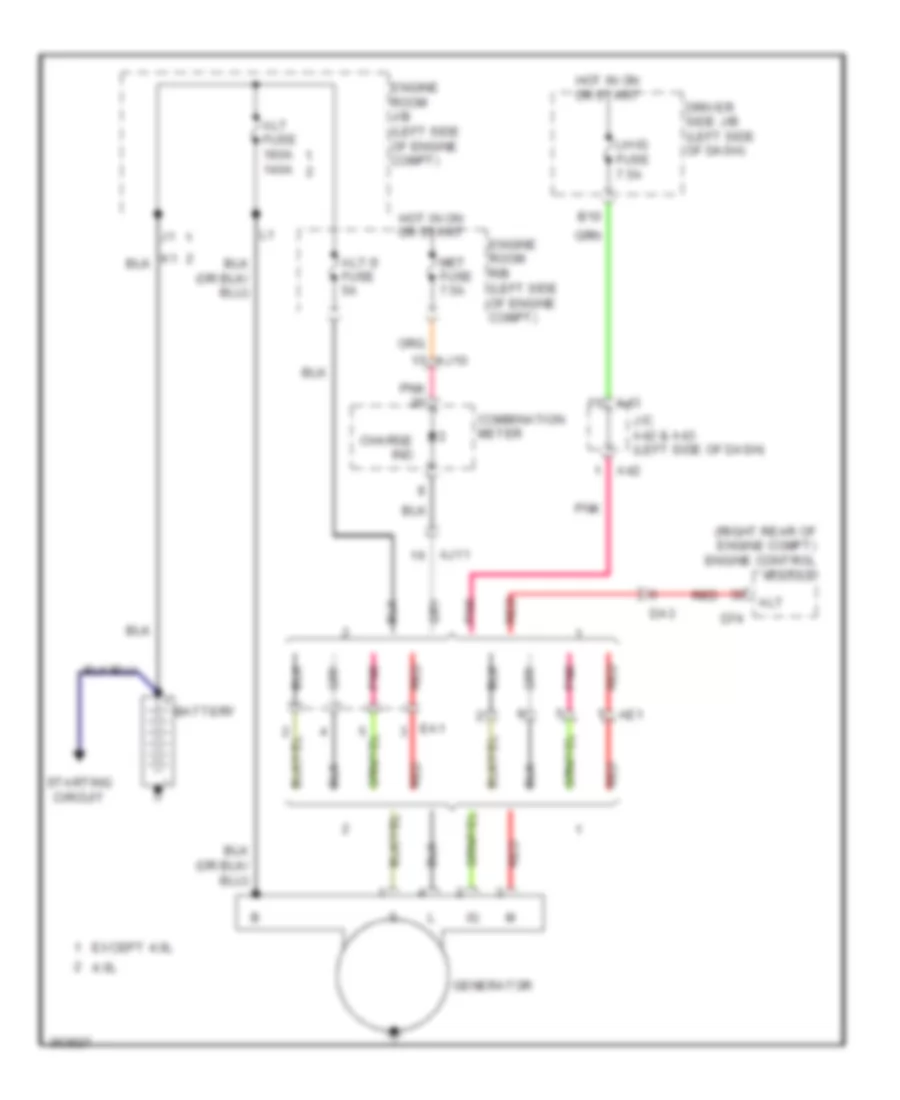
ENGINE PERFORMANCE
4.0L
4.0L, Engine Performance Wiring Diagram (1 of 6) for Toyota Tundra SR5 2012
List of elements for 4.0L, Engine Performance Wiring Diagram (1 of 6) for Toyota Tundra SR5 2012:
- (air intake duct) mass air flow meter
- (left side of engine compt) vvt sensor (bank 1 exhaust side)
- (on throttle body) throttle position sensor
- (rear of engine compt) d9
- (right front of engine) power steering oil pressure switch
- (top left of engine) fuel injector 3
- (top left of engine) fuel injector 5
- (top of engine) fuel injector 1
- (top right of engine) fuel injector 2
- (top right of engine) fuel injector 4
- (top right of engine) fuel injector 6
- A1a+
- A1a-
- A2a+
- A2a-
- Air fuel ratio sensor (bank 1 sensor 1) (left side exhaust, before catalytic converter)
- Air fuel ratio sensor (bank 2 sensor 1) (right side exhaust, before catalytic converter)
- D74
- D8 (rear of engine compt)
- Da1
- Da2
- E2g
- Ekn2
- Eknk
- Engine control module (right rear of engine compt)
- Eta
- Etha
- Ethw
- Ev1+
- Ev1-
- Ex+
- Ex-
- Ex1b
- Ex2b
- Ha1a
- Ha2a
- Heated oxygen sensor (bank 1 sensor 2) (left side exhaust, after catalytic converter)
- Heated oxygen sensor (bank 2 sensor 2) (right side exhaust, after catalytic converter)
- Ht1b
- Ht2b
- Igf1
- Knk1
- Knk2
- Knock sensor (bank 2) (left front of engine)
- Me01
- Nca
- Ne+
- Ne-
- Nsw
- Nt+
- Nt-
- Ox1b
- Ox2b
- Pnk
- Ppmp
- Psp
- Red
- Sp2+
- Sp2-
- Tha
- Tho1
- Tho2
- Thw
- Transmission revolution sensor (turbine) (in transmission)
- Vc2
- Vcta
- Vcv1
- Vcv2
- Vta
- Vta1
- Vta2
- Vv1+
- Vv1-
- Vv2+
- Vv2-
4.0L, Engine Performance Wiring Diagram (2 of 6) for Toyota Tundra SR5 2012
List of elements for 4.0L, Engine Performance Wiring Diagram (2 of 6) for Toyota Tundra SR5 2012:
- (left front of engine compt) engine coolant temperature sensor
- (left front of engine compt) j/c a44
- (left side of engine) vvt sensor (bank 1 intake side)
- (right side of engine) vvt sensor (bank 2 intake side)
- A/f fuse 15a
- A/f relay
- A2 (left side of engine compt)
- Camshaft timing oil control valve (bank 1 exhaust side) (left front of engine)
- Camshaft timing oil control valve (bank 1) intake side) (left front of engine)
- Camshaft timing oil control valve (bank 2 exhaust side) (right front of engine)
- Camshaft timing oil control valve (bank 2) intake side) (right front of engine)
- Crankshaft position sensor (front of engine)
- D9 (rear of engine compt)
- Da3
- Da2
- Efi 1 fuse 25a
- Efi relay
- Engine room j/b (left side of engine compt)
- Hot at all times
- J/c d71 (right rear of engine compt)
- Knock sensor (bank 1) (right front of engine)
- Nca
- Purge vsv (left side of engine)
- Red
- Vvl+
- Vvl-
- Vvr+
- Vvr-
4.0L, Engine Performance Wiring Diagram (3 of 6) for Toyota Tundra SR5 2012
List of elements for 4.0L, Engine Performance Wiring Diagram (3 of 6) for Toyota Tundra SR5 2012:
- (front of engine compt) air pump
- (rear of engine) air switching valve (bank 1)
- (rear of engine) air switching valve (bank 2)
- (right side of engine compt) vvt sensor (bank 2 exhaust side)
- +bl
- Ai pmp htr fuse 10a
- Ai-vsv relay
- Aip
- Aip2
- Air injection control driver
- Air1
- Airp
- Batt
- D10 (rear of engine)
- D74
- D8 (rear of engine compt)
- D86
- D87
- D9 (rear of engine compt)
- Da2
- E03
- E22
- Engine control module (right rear of engine compt)
- Engine room r/b (left side of engine compt)
- Ev2+
- Ev2-
- Ex+
- Ex-
- Gnd
- Gndl
- Hot at all times
- Igf
- Ignition coil 2 (top right of engine)
- Ignition coil 3 (top left of engine)
- Ignition coil 5 (top left of engine)
- Igt2
- Igt3
- Igt5
- J/c d72 (right rear of engine compt)
- Oc1+
- Oc1-
- Oc2+
- Oc2-
- Oe1+
- Oe1-
- Oe2+
- Oe2-
- Pnk
- Prg
- Red
- Sip
- Siv
- Vc2
4.0L, Engine Performance Wiring Diagram (4 of 6) for Toyota Tundra SR5 2012
List of elements for 4.0L, Engine Performance Wiring Diagram (4 of 6) for Toyota Tundra SR5 2012:
- (near fuel tank) canister pump module
- (rear of engine compt) d9
- A/pump fuse 50a
- A38
- A42
- A43
- Automatic transmission
- Canister pressure sensor
- Da1
- Da2
- Da3
- Efi 2 fuse 10a
- Engine room j/b (left side of engine compt)
- Engine room r/b (left side of engine compt)
- Etcs fuse 10a
- F/pmp fuse 15a
- Hot at all times
- Hot in on or start
- Ign fuse 10a
- Inj fuse 10a
- J/c a38 & a39 (left side of a39 dash)
- J/c a42 & a43 (left side of dash)
- Leak detection pump
- Ot+
- Ot-
- Ot2+
- Ot2-
- Pnk
- Ra1
- Red
- Sl1+
- Sl1-
- Sl2+
- Sl2-
- Slt+
- Slt-
- Slu+
- Slu-
- Stop fuse 15a
- Stop light switch
- Transmission revolution sensor (electronically controlled transmission) (transmission assembly)
- Vent valve
4.0L, Engine Performance Wiring Diagram (5 of 6) for Toyota Tundra SR5 2012
List of elements for 4.0L, Engine Performance Wiring Diagram (5 of 6) for Toyota Tundra SR5 2012:
- (center of dash) j/c j77
- (rear of engine compt) d8
- (rear of engine compt) d9
- +bm
- A/t oil temp ind
- A40
- A41
- A45
- Acc
- Aidi
- Airv
- Aj4
- Aj9
- Alt
- Buzzer
- Canh
- Canl
- Combination meter
- Computer data lines system
- D73
- D74
- D9 (rear of engine compt)
- Da1
- Dim
- Diode (starting) (right side of dash)
- E01
- E02
- E04
- E05
- Engine control module (right rear of engine compt)
- Ge01
- Ha1a
- Ha2a
- Hot at all times
- Ht1b
- Ht2b
- Ignition switch
- Igt1
- Igt2
- Igt3
- Igt4
- Igt5
- Igt6
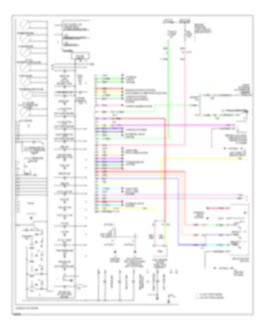
- Instrument cluster system
- J/c a40 & a41 (right side of dash) a41
- J/c a45 & d73 (right rear of engine d73 compt)
- J/c j117 (right side of dash)
- J/c j71 (left side of dash)
- J/c j75 & j76 (left side of dash)
- J/c j78 (left side of dash)
- J75
- J76
- Lcd (sequential shift)
- Left side of dash) (floor shift: left kick panel) j1
- Lock
- Mal- function ind
- Off
- Park/neutral position switch (transmission assembly)
- Pnk
- Power circuit
- Red
- Sl1+
- Sl1-
- Sl2+
- Sl2-
- Slt+
- Slt-
- Slu+
- Slu-
- Star
- Start
- Starting/ charging system
- Starting/charging system
4.0L, Engine Performance Wiring Diagram (6 of 6) for Toyota Tundra SR5 2012
List of elements for 4.0L, Engine Performance Wiring Diagram (6 of 6) for Toyota Tundra SR5 2012:
- (fuel tank assembly) fuel pump control ecu
- (fuel tank assembly) fuel sender gauge
- (left side of dash) j/c j74
- +b2
- A24
- A4 (right side of engine compt)
- Ac1
- Acc fuse 7.5a
- Accelerator pedal position sensor (column shift: left side of dash)
- Act
- Aip
- Aip2
- Air conditioning system
- Aj10
- Aj4
- Anti-theft system
- Batt
- Bk/up lp fuse 10a
- Canh
- Canl
- Ccs
- Column shift
- Computer data lines system
- Cruise control system
- D55
- D65
- D9 (rear of engine compt)
- Da1
- Diode (ignition) (column shift) (left side of dash)
- Driver side j/b (left side of dash)
- Engine control module (right rear of engine compt)
- Engine room r/b (left side of engine compt)
- Epa
- Epa2
- F/pmp relay
- Floor
- Floor shift
- Fp-
- Fpc
- Gnd
- Hot in on or acc
- Hot in on or start
- Igf
- Ignition coil (top left of engine)
- Ignition coil (top right of engine)
- Igsw
- Igt1
- Igt4
- Igt6
- Ill+
- Ill-
- Imi
- Imo
- Instrument cluster system
- Interior lights system
- J/c a36 (right side of dash)
- J/c d72 (right rear of engine compt)
- J/c j71 (left side of dash)
- J/c j73 & j74 (left side of dash)
- J/c j73 & j74 (left side of dash) j73
- J/c j79 & j80 (left side of dash)
- J3 (right kick panel)
- J73
- J74
- J79
- J80
- Lh-ig fuse 7.5a
- Met fuse 7.5a
- Mpmp
- Mrel
- Pnk
- Pump
- Ra1
- Ra2
- Ra3
- Red
- Sender
- Sftd
- Sftu
- Shift
- Spd
- St1-
- Sta
- Starting/charging system
- Stp
- Stsw
- Tach
- Transmission control switch
- Vcp2
- Vcpa
- Vpa
- Vpa2
- Vpmp
4.6L
4.6L, Engine Performance Wiring Diagram (1 of 8) for Toyota Tundra SR5 2012
List of elements for 4.6L, Engine Performance Wiring Diagram (1 of 8) for Toyota Tundra SR5 2012:
- (air intake duct) mass air flow meter
- (on throttle body) throttle position sensor
- (top left of engine) fuel injector 3
- (top left of engine) fuel injector 5
- (top left of engine) fuel injector 7
- (top of engine) fuel injector 1
- (top right of engine) fuel injector 2
- (top right of engine) fuel injector 4
- (top right of engine) fuel injector 6
- (top right of engine) fuel injector 8
- A1a+
- A1a-
- A2a+
- A2a-
- Air fuel ratio sensor (bank 1 sensor 1) (left side exhaust, before catalytic converter)
- Air fuel ratio sensor (bank 2 sensor 1) (right side exhaust, before catalytic converter)
- D1 (rear of engine compt)
- D2 (rear of engine compt)
- D74
- Da1
- Df1
- Dh1
- Da1
- E2g
- Ekn2
- Ekn4
- Eknk
- Engine control module (right rear of engine compt)
- Enk3
- Eta
- Ev1+
- Ev1-
- Ex1b
- Ex2b
- G2-
- Ha1a
- Ha2a
- Heated oxygen sensor (bank 1 sensor 2) (left side exhaust, after catalytic converter)
- Heated oxygen sensor (bank 2 sensor 2) (right side exhaust, after catalytic converter)
- Ht1b
- Ht2b
- Igf1
- Igf2
- J/c d71 (right rear of engine compt)
- Knk1
- Knk2
- Knk3
- Knk4
- Knock sensor (bank 2 sensor 1) (right side of engine)
- Me01
- Nca
- Ne+
- Ne-
- Nsw
- Nt+
- Nt-
- Ox1b
- Ox2b
- Pim
- Pnk
- Ppmp
- Psp
- Red
- Sp2+
- Sp2-
- Tha
- Tho1
- Tho2
- Thw
- Transmission revolution sensor (turbine) (in transmission)
- Vcta
- Vcv1
- Vcv2
- Vta
- Vta1
- Vta2
- Vv1+
- Vv1-
- Vv2+
- Vv2-
4.6L, Engine Performance Wiring Diagram (2 of 8) for Toyota Tundra SR5 2012
List of elements for 4.6L, Engine Performance Wiring Diagram (2 of 8) for Toyota Tundra SR5 2012:
- (left front of engine compt) engine coolant temperature sensor
- (left front of engine compt) j/c a44
- (left side of engine compt) vvt sensor (bank 1 exhaust side)
- (left side of engine compt) vvt sensor (bank 1 intake side)
- A/f fuse 15a
- A/f relay
- A/pump fuse 50a
- A2 (left side of engine compt)
- Camshaft position sensor (left front of engine)
- Crankshaft position sensor (left front of engine)
- Da3
- Da1
- Efi 1 fuse 25a
- Efi relay
- Engine room j/b (left side of engine compt)
- Ex+
- Ex-
- Hot at all times
- Intake manifold vacuum sensor (left front of engine)
- J/c d71 (right rear of engine compt)
- Knock sensor (bank 1 sensor 1) (left front of engine)
- Knock sensor (bank 1 sensor 2) (right rear of engine)
- Knock sensor (bank 2 sensor 2) (right side of engine)
- Ne+
- Ne-
- Pim
- Purge vsv (left side of engine)
- Red
- Vc2
- Vvl+
- Vvl-
4.6L, Engine Performance Wiring Diagram (3 of 8) for Toyota Tundra SR5 2012
List of elements for 4.6L, Engine Performance Wiring Diagram (3 of 8) for Toyota Tundra SR5 2012:
- (left side of engine compt) air injection control driver (bank 2)
- (rear of engine compt) d1
- (right front of engine compt) air pump (bank 2)
- (right front of engine) egr control valve sub-assembly
- (right side of engine compt) vvt sensor (bank 2 exhaust side)
- (right side of engine) vvt sensor (bank 2 intake side)
- +b1
- +b2
- Acis
- Acis vsv (rear of engine)
- Airp
- Arp2
- Bat2
- Camshaft timing oil control valve (bank 1 exhaust side) (left front of engine)
- Camshaft timing oil control valve (bank 1 intake side) (left front of engine)
- Camshaft timing oil control valve (bank 2 exhaust side) (right front of engine)
- Camshaft timing oil control valve (bank 2 intake side) (right front of engine)
- D2 (rear of engine compt)
- D52
- D54
- D74
- Da1
- Di2
- E03
- Egr1
- Egr2
- Egr3
- Egr4
- Engine control module (right rear of engine compt)
- Ev2+
- Ev2-
- Ex+
- Ex-
- Ht1b
- Ht2b
- Oc1+
- Oc1-
- Oc2+
- Oc2-
- Oe1+
- Oe1-
- Oe2+
- Oe2-
- Pnk
- Prg
- Red
- Sip2
- Siv2
- Vc2
- Vp2
- Vv2
- Vvr+
- Vvr-
4.6L, Engine Performance Wiring Diagram (4 of 8) for Toyota Tundra SR5 2012
List of elements for 4.6L, Engine Performance Wiring Diagram (4 of 8) for Toyota Tundra SR5 2012:
- (left rear of engine compt) air injection control driver (bank 1)
- (rear of engine compt) d3
- (rear of engine) air switching valve (bank 1)
- (right front of engine) power steering oil pressure sensor
- (right rear of engine) air switching valve (bank 2)
- (top of engine) air pump (bank 1)
- +bl
- Aip
- Aip2
- Batt
- D3 (rear of engine compt)
- D48
- D50
- E22
- Gnd
- Gndl
- Igf2
- Ignition coil 2 (top right of engine)
- Ignition coil 3 (top left of engine)
- Ignition coil 5 (top left of engine)
- Ignition coil 8 (top right of engine)
- Igt2
- Igt3
- Igt5
- Igt8
- J/c d72 (right rear of engine compt)
- Noise filter (ignition bank 1) (left rear of engine)
- Pnk
- Psp
- Red
- Sip
- Siv
- Transmission revolution sensor (electronically controlled transmission) (transmission assembly)
- Vc2
4.6L, Engine Performance Wiring Diagram (5 of 8) for Toyota Tundra SR5 2012
List of elements for 4.6L, Engine Performance Wiring Diagram (5 of 8) for Toyota Tundra SR5 2012:
- (near fuel tank) canister pump module
- A/pump fuse 50a
- A38
- A42
- A43
- Canister pressure sensor
- D2 (rear of engine compt)
- Da1
- Da2
- Da3
- Efi 2 fuse 10a
- Engine room j/b (left side of engine compt)
- Engine room r/b (left side of engine compt)
- Etcs fuse 10a
- Hot at all times
- Hot in on or start
- Ign fuse 10a
- Inj fuse 10a
- J/c a38 & a39 (left side of a39 dash)
- J/c a42 & a43 (left side of dash)
- J/c a43 (left side of dash)
- Leak detection pump
- Ot+
- Ot-
- Ot2+
- Ot2-
- Pnk
- Ra1
- Red
- S3 automatic transmission
- Sl1+
- Sl1-
- Sl2+
- Sl2-
- Slt+
- Slt-
- Slu+
- Slu-
- Stop fuse 15a
- Stop light switch
- Vent valve
4.6L, Engine Performance Wiring Diagram (6 of 8) for Toyota Tundra SR5 2012
List of elements for 4.6L, Engine Performance Wiring Diagram (6 of 8) for Toyota Tundra SR5 2012:
- (column shift: left side of dash) (floor shift: left kick panel) j1
- (rear
- +bm
- A/t oil temperature ind
- A40
- A41
- A45
- Acc
- Aid2
- Aidi
- Airv
- Aj4
- Aj9
- Alt
- Buzzer
- Canh
- Canl
- Combination meter
- Computer data lines system
- D1 (rear of engine compt)
- D2 (rear of engine compt)
- D73
- D74 e01
- Da1
- Dim
- Diode (starting) (right side of dash)
- E02
- E04
- E05
- Egr2
- Egr3
- Engine control module (right rear of engine compt)
- Ge01
- Ha1a
- Ha2a
- Hot at all times
- Ignition switch
- Igt1
- Igt2
- Igt3
- Igt4
- Igt5
- Igt6
- Igt7
- Igt8
- Instrument cluster system
- Interior lights system
- J/c a40 & a41 (right side of dash)
- J/c a45 & d73 (right rear of engine compt) d73
- J/c j117 (right side of dash)
- J/c j71 (left side of dash)
- J/c j75 & j76 (left side of dash)
- J/c j77 (center of dash)
- J/c j78 (left side of dash)
- J3 (right kick panel)
- J75
- J76
- Lcd (sequential shift)
- Lock
- Mal- function ind
- Of engine compt) d2
- Off
- Park/neutral position switch (transmission assembly)
- Pnk
- Power circuit
- Red
- Sl1+
- Sl1-
- Sl2+
- Sl2-
- Slt+
- Slt-
- Slu+
- Slu-
- Star
- Start
- Starting/ charging system
- Starting/charging system
- Tow haul ind
- Tow/haul pattern select switch (floor shift)
4.6L, Engine Performance Wiring Diagram (7 of 8) for Toyota Tundra SR5 2012
List of elements for 4.6L, Engine Performance Wiring Diagram (7 of 8) for Toyota Tundra SR5 2012:
- Acc fuse 7.5a
- Aj4
- Bk/up lp fuse 10a
- Column shift
- D3 (rear of engine compt)
- D55
- D65
- Da1
- Diode (ignition) (column shift) (left side of dash)
- Driver side j/b (left side of dash)
- Floor shift
- Gnd
- Hot in on or acc
- Hot in on or start
- Igf1
- Ignition coil 1 (top left of engine)
- Ignition coil 4 (top right of engine)
- Ignition coil 6 (top right of engine)
- Ignition coil 7 (top left of engine)
- Igt1
- Igt4
- Igt6
- Igt7
- J/c d72 (right rear of engine compt)
- J/c j71 (left side of dash)
- J/c j73 & j74 (left side of dash)
- J73
- J74
- Lh-ig fuse 7.5a
- Noise filter (ignition bank 2) (right
- Pnk
- Rear of engine)
- Red
4.6L, Engine Performance Wiring Diagram (8 of 8) for Toyota Tundra SR5 2012
List of elements for 4.6L, Engine Performance Wiring Diagram (8 of 8) for Toyota Tundra SR5 2012:
- (left side of dash) j/c j74
- (right side of engine compt)
- +b2
- 2wd
- A2 (left side of engine compt)
- A24
- A4 (right side of engine compt)
- Ac1
- Accelerator pedal position sensor (column shift: left side of dash)
- Accr
- Act
- Adj1
- Aip
- Aip2
- Air conditioning system
- Aj10
- Aj4
- Anti-theft system
- Arv2
- Batt
- Canh
- Canl
- Ccs
- Column shift
- Computer data lines system
- Cruise control system
- Da1
- Defogger system
- Els2
- Engine control module (right rear of engine compt)
- Engine room r/b (left side of engine compt)
- Epa
- Epa2
- F/pmp fuse 15a
- F/pmp relay
- Floor shift
- Fp-
- Fpc
- Fuel pump control ecu (fuel tank assembly)
- Fuel sender gauge (fuel tank assembly)
- Hot at all times
- Hot in on or start
- Igsw
- Ill+
- Ill-
- Imi
- Imo
- Instrument cluster system
- Interior lights system
- J/c a36 (right side of dash)
- J/c a44 (left front of engine compt)
- J/c j79 & j80 (left side of dash)
- J3 (right kick panel)
- J79
- J80
- Key interlock solenoid
- Met fuse 7.5a
- Mpmp
- Mrel
- Pnk
- Pump
- Pwr
- Ra1
- Ra2
- Ra3
- Red
- Sftd
- Sftu
- Shift interlock system
- Sls+
- Spd
- St1-
- Sta
- Starting/charging system
- Stp
- Stsw
- Tach
- Tfn
- Transmission control switch
- Transmissions system
- Vcp2
- Vcpa
- Vpa
- Vpa2
- Vpmp
5.7L
5.7L, Engine Performance Wiring Diagram (1 of 7) for Toyota Tundra SR5 2012
List of elements for 5.7L, Engine Performance Wiring Diagram (1 of 7) for Toyota Tundra SR5 2012:
- (air intake duct) mass air flow meter
- (on throttle body) throttle position sensor
- (top left of engine) fuel injector 3
- (top left of engine) fuel injector 5
- (top left of engine) fuel injector 7
- (top of engine) fuel injector 1
- (top right of engine) fuel injector 2
- (top right of engine) fuel injector 4
- (top right of engine) fuel injector 6
- (top right of engine) fuel injector 8
- A1a+
- A1a-
- A2a+
- A2a-
- Air fuel ratio sensor (bank 1 sensor 1) (left side exhaust, before catalytic converter)
- Air fuel ratio sensor (bank 2 sensor 1) (right side exhaust, before catalytic converter)
- D1 (rear of engine compt)
- D2 (rear of engine compt)
- D74
- Da1
- Df1
- Dh1
- Da1
- E2g
- Ekn2
- Ekn4
- Eknk
- Engine control module (right rear of engine compt)
- Enk3
- Eta
- Etha
- Ethw
- Ev1+
- Ev1-
- Ex1b
- Ex2b
- G2-
- Ha1a
- Ha2a
- Heated oxygen sensor (bank 1 sensor 2) (left side exhaust, after catalytic converter)
- Heated oxygen sensor (bank 2 sensor 2) (right side exhaust, after catalytic converter)
- Ht1b
- Ht2b
- Igf1
- Igf2
- J/c d71 (right rear of engine compt)
- Knk1
- Knk2
- Knk3
- Knk4
- Knock sensor (bank 2 sensor 1) (left front of engine)
- Me01
- Nca
- Ne+
- Ne-
- Nsw
- Nt+
- Nt-
- Ox1b
- Ox2b
- Pnk
- Ppmp
- Psp
- Red
- Sp2+
- Sp2-
- Tha
- Tho1
- Tho2
- Thw
- Transmission revolution sensor (turbine) (in transmission)
- Vcta
- Vcv1
- Vcv2
- Vta
- Vta1
- Vta2
- Vv1+
- Vv1-
- Vv2+
- Vv2-
5.7L, Engine Performance Wiring Diagram (2 of 7) for Toyota Tundra SR5 2012
List of elements for 5.7L, Engine Performance Wiring Diagram (2 of 7) for Toyota Tundra SR5 2012:
- (left front of engine compt) engine coolant temperature sensor
- (left front of engine compt) j/c a44
- (left side of engine compt) vvt sensor (bank 1 exhaust side)
- (left side of engine) vvt sensor (bank 1 intake side)
- A/f fuse 15a
- A/f relay
- A/pump fuse 50a
- A2 (left side of engine compt)
- Camshaft position sensor (left front of engine)
- Crankshaft position sensor (left rear of engine)
- Da3
- Da1
- Efi 1 fuse 25a
- Efi relay
- Engine room j/b (left side of engine compt)
- Ex+
- Ex-
- Hot at all times
- J/c d71 (right rear of engine compt)
- Knock sensor (bank 1 sensor 1) (right front of engine)
- Knock sensor (bank 1 sensor 2) (right rear of engine)
- Knock sensor (bank 2 sensor 2) (left rear of engine)
- Ne+
- Ne-
- Purge vsv (top center of engine)
- Red
- Vc2
- Vvl+
- Vvl-
5.7L, Engine Performance Wiring Diagram (3 of 7) for Toyota Tundra SR5 2012
List of elements for 5.7L, Engine Performance Wiring Diagram (3 of 7) for Toyota Tundra SR5 2012:
- (double cab: right rear of vehicle) (regular cab: tailgate) r1
- (fuel tank assembly) (5.7l flex fuel) fuel tank solenoid valve
- (left side of engine compt) air injection control driver (bank 2)
- (rear of engine compt) d1
- (right front of engine compt) air pump (bank 2)
- (right side of engine compt) vvt sensor (bank 2 exhaust side)
- (right side of engine) vvt sensor (bank 2 intake side)
- +b2
- Acis
- Acis vsv (rear of engine)
- Ai htr relay
- Airp
- Aph+
- Aphg
- Arp2
- Bat2
- Camshaft timing oil control valve (bank 1 exhaust side) (left front of engine)
- Camshaft timing oil control valve (bank 1 intake side) (left front of engine)
- Camshaft timing oil control valve (bank 2 exhaust side) (right front of engine)
- Camshaft timing oil control valve (bank 2 intake side) (right front of engine)
- D2 (rear of engine compt)
- D3 (rear of engine compt)
- D52
- D54
- D74
- Da1
- Da2
- Di2
- E03
- Engine control module (right rear of engine compt)
- Engine room r/b (left side of engine compt)
- Ev2+
- Ev2-
- Ex+
- Ex-
- F/pmp vsv relay (5.7l flex fuel)
- Fpcr
- Gnd
- Hai1
- Oc1+
- Oc1-
- Oc2+
- Oc2-
- Oe1+
- Oe1-
- Oe2+
- Oe2-
- Pnk
- Prg
- Ra1
- Red
- Sip2
- Siv2
- Vc2
- Vp2
- Vv2
- Vvr+
- Vvr-
5.7L, Engine Performance Wiring Diagram (4 of 7) for Toyota Tundra SR5 2012
List of elements for 5.7L, Engine Performance Wiring Diagram (4 of 7) for Toyota Tundra SR5 2012:
- (front of engine compt) air pump (bank 1)
- (left rear of engine compt) air injection control driver (bank 1)
- (rear of engine compt) d3
- (rear of engine) air switching valve (bank 1)
- (rear of engine) air switching valve (bank 2)
- (right front of engine) power steering oil pressure sensor
- +b d50
- +bl
- Ai pmp htr fuse 10a
- Aip
- Aip2
- Aph+ pnk
- Batt
- D3 (rear of engine compt)
- E22
- Engine room r/b (left side of engine compt)
- Gnd
- Gndl
- Hot at all times
- Igf2
- Ignition coil 2 (top right of engine)
- Ignition coil 3 (top left of engine)
- Ignition coil 5 (top left of engine)
- Ignition coil 8 (top right of engine)
- Igt2
- Igt3
- Igt5
- Igt8
- J/c d72 (right rear of engine compt)
- Pnk
- Psp
- Red
- Sip
- Siv
- Vc2
- Vp d48
5.7L, Engine Performance Wiring Diagram (5 of 7) for Toyota Tundra SR5 2012
List of elements for 5.7L, Engine Performance Wiring Diagram (5 of 7) for Toyota Tundra SR5 2012:
- (near fuel tank) canister pump module
- (rear of engine compt) d2
- A/pump fuse 50a
- A38
- A42
- A43
- Automatic transmission
- Canister pressure sensor
- D63
- D64
- Da1
- Da2
- Da3
- Efi 2 fuse 10a
- Engine room j/b (left side of engine compt)
- Engine room r/b (left side of engine compt)
- Etcs fuse 10a
- Hot at all times
- Hot in on or start
- Ign fuse 10a
- Inj fuse 10a
- J/c a38 & a39 (left side of a39 dash)
- J/c a42 & a43 (left side of dash)
- J/c a42 & a43 (left side of dash) a42
- Leak detection pump
- Ot+
- Ot-
- Ot2+
- Ot2-
- Pnk
- Ra1
- Red
- Sl1+
- Sl1-
- Sl2+
- Sl2-
- Slt+
- Slt-
- Slu+
- Slu-
- Stop fuse 15a
- Stop light switch
- Transmission revolution sensor (electronically controlled transmission) (transmission assembly)
- Vent valve
5.7L, Engine Performance Wiring Diagram (6 of 7) for Toyota Tundra SR5 2012
List of elements for 5.7L, Engine Performance Wiring Diagram (6 of 7) for Toyota Tundra SR5 2012:
- (rear
- +bm
- A/t oil temp ind
- A40
- A41
- A45
- Acc
- Aid2
- Aidi
- Airv
- Aj4
- Aj9
- Alt
- Buzzer
- Combination meter
- Computer data lines system
- D1 (rear of engine compt)
- D2 (rear of engine compt)
- D73
- D74
- Da1
- Dim
- Diode (starting) (right side of dash)
- E01
- E02
- E04
- E05
- Engine control module (right rear of engine compt)
- Ge01
- Ha1a
- Ha2a
- Hot at all times
- Ht1b
- Ht2b
- Ignition switch
- Igt1
- Igt2
- Igt3
- Igt4
- Igt5
- Igt6
- Igt7
- Igt8
- Instrument cluster system
- Interior lights system
- J/c a40 & a41 (right side of dash)
- J/c a45 & d73 (right rear of engine compt) d73
- J/c j117 (right side of dash)
- J/c j71 (left side of dash)
- J/c j75 & j76 (left side of dash)
- J/c j77 (center of dash)
- J/c j78 (left side of dash)
- J3 (right kick panel)
- J75
- J76
- Lcd (sequential shift)
- Left side of dash) (floor shift: left kick panel) j1
- Lock
- Mal- function ind
- Of engine compt) d2
- Off
- Park/neutral position switch (transmission assembly)
- Pnk
- Power circuit
- Red
- Sl1+
- Sl1-
- Sl2+
- Sl2-
- Slt+
- Slt-
- Slu+
- Slu-
- Star
- Start
- Starting/ charging system
- Starting/charging system
- Tow haul ind
- Tow/haul pattern select switch (floor shift)
5.7L, Engine Performance Wiring Diagram (7 of 7) for Toyota Tundra SR5 2012
List of elements for 5.7L, Engine Performance Wiring Diagram (7 of 7) for Toyota Tundra SR5 2012:
- (5.7l flex fuel) c/opn relay
- (left side of dash) j/c j74
- (left side of engine compt) a2
- (pin 6 to 9 not used)
- +b2
- 2wd
- 5.7l
- 5.7l flex fuel
- A24
- A4 (right side of engine compt)
- Ac1
- Acc fuse 7.5a
- Accelerator pedal position sensor (column shift: left side of dash)
- Accr
- Act
- Adj1
- Aip
- Aip2
- Air conditioning system
- Aj10
- Aj4
- Anti-theft system
- Arv2
- Batt
- Bk/up lp fuse 10a
- Canh
- Canl
- Ccs
- Column shift
- Computer data lines system
- Cruise control system
- D3 (rear of engine compt)
- D55
- D65
- Da1
- Dash)
- Defogger system
- Diode (ignition) (column shift) (left side) of dash)
- Driver side j/b (left side of dash)
- Els2
- Engine control module (right rear of engine compt)
- Engine room r/b (left side of engine compt)
- Epa
- Epa2
- F/pmp fuse 15a
- F/pmp relay
- Floor shift
- Fp-
- Fpc
- Fuel pump control ecu (fuel tank assembly)
- Fuel sender gauge (fuel tank assembly)
- Gnd
- Hot at all times
- Hot in on or acc
- Hot in on or start
- Igf1
- Ignition coil 1 (top left of engine)
- Ignition coil 4 (top right of engine)
- Ignition coil 6 (top right of engine)
- Ignition coil 7 (top left of engine)
- Igsw
- Igt1
- Igt4
- Igt6
- Igt7
- Ill+
- Ill-
- Imi
- Imo
- Instrument cluster system
- Interior lights system
- J/c a36 (right side of dash)
- J/c a44 (left front of engine compt)
- J/c d72 (right rear of engine compt)
- J/c j71 (left side of dash)
- J/c j73 & j74 (left side of dash)
- J/c j73 & j74 (left side of dash) j73
- J/c j73 & j74 (left side of j74
- J/c j79 & j80 (left side of dash)
- J3 (right kick panel)
- J73
- J74
- J79
- J80
- Lh-ig fuse 7.5a
- Met fuse 7.5a
- Mpmp
- Mrel
- Pnk
- Pump
- R11
- Ra1
- Ra2
- Ra3
- Ra4
- Red
- Sender
- Sftd
- Sftu
- Spd
- St1-
- Sta
- Starting/ charging system
- Starting/charging system
- Stp
- Stsw
- Tach
- Tfn
- Tow
- Transmission control switch
- Transmissions system
- Vcp2
- Vcpa
- Vpa
- Vpa2
- Vpmp
5.7L FLEX FUEL
5.7L Flex Fuel, Engine Performance Wiring Diagram (1 of 7) for Toyota Tundra SR5 2012
List of elements for 5.7L Flex Fuel, Engine Performance Wiring Diagram (1 of 7) for Toyota Tundra SR5 2012:
- (air intake duct) mass air flow meter
- (on throttle body) throttle position sensor
- (top left of engine) fuel injector 3
- (top left of engine) fuel injector 5
- (top left of engine) fuel injector 7
- (top of engine) fuel injector 1
- (top right of engine) fuel injector 2
- (top right of engine) fuel injector 4
- (top right of engine) fuel injector 6
- (top right of engine) fuel injector 8
- A1a+
- A1a-
- A2a+
- A2a-
- Air fuel ratio sensor (bank 1 sensor 1) (left side exhaust, before catalytic converter)
- Air fuel ratio sensor (bank 2 sensor 1) (right side exhaust, before catalytic converter)
- D1 (rear of engine compt)
- D2 (rear of engine compt)
- D74
- Da1
- Df1
- Dh1
- Da1
- E2g
- Ekn2
- Ekn4
- Eknk
- Engine control module (right rear of engine compt)
- Enk3
- Eta
- Etha
- Ethw
- Ev1+
- Ev1-
- Ex1b
- Ex2b
- G2-
- Ha1a
- Ha2a
- Heated oxygen sensor (bank 1 sensor 2) (left side exhaust, after catalytic converter)
- Heated oxygen sensor (bank 2 sensor 2) (right side exhaust, after catalytic converter)
- Ht1b
- Ht2b
- Igf1
- Igf2
- J/c d71 (right rear of engine compt)
- Knk1
- Knk2
- Knk3
- Knk4
- Knock sensor (bank 2 sensor 1) (left front of engine)
- Me01
- Nca
- Ne+
- Ne-
- Nsw
- Nt+
- Nt-
- Ox1b
- Ox2b
- Pnk
- Ppmp
- Psp
- Red
- Sp2+
- Sp2-
- Tha
- Tho1
- Tho2
- Thw
- Transmission revolution sensor (turbine) (in transmission)
- Vcta
- Vcv1
- Vcv2
- Vta
- Vta1
- Vta2
- Vv1+
- Vv1-
- Vv2+
- Vv2-
5.7L Flex Fuel, Engine Performance Wiring Diagram (2 of 7) for Toyota Tundra SR5 2012
List of elements for 5.7L Flex Fuel, Engine Performance Wiring Diagram (2 of 7) for Toyota Tundra SR5 2012:
- (left front of engine compt) engine coolant temperature sensor
- (left front of engine compt) j/c a44
- (left side of engine compt) vvt sensor (bank 1 exhaust side)
- (left side of engine) vvt sensor (bank 1 intake side)
- A/f fuse 15a
- A/f relay
- A/pump fuse 50a
- A2 (left side of engine compt)
- Camshaft position sensor (left front of engine)
- Crankshaft position sensor (left rear of engine)
- Da3
- Da1
- Efi 1 fuse 25a
- Efi relay
- Engine room j/b (left side of engine compt)
- Ex+
- Ex-
- Hot at all times
- J/c d71 (right rear of engine compt)
- Knock sensor (bank 1 sensor 1) (right front of engine)
- Knock sensor (bank 1 sensor 2) (right rear of engine)
- Knock sensor (bank 2 sensor 2) (left rear of engine)
- Ne+
- Ne-
- Purge vsv (top center of engine)
- Red
- Vc2
- Vvl+
- Vvl-
5.7L Flex Fuel, Engine Performance Wiring Diagram (3 of 7) for Toyota Tundra SR5 2012
List of elements for 5.7L Flex Fuel, Engine Performance Wiring Diagram (3 of 7) for Toyota Tundra SR5 2012:
- (double cab: right rear of vehicle) (regular cab: tailgate) r1
- (fuel tank assembly) (5.7l flex fuel) fuel tank solenoid valve
- (left side of engine compt) air injection control driver (bank 2)
- (rear of engine compt) d1
- (right front of engine compt) air pump (bank 2)
- (right side of engine compt) vvt sensor (bank 2 exhaust side)
- (right side of engine) vvt sensor (bank 2 intake side)
- +b2
- Acis
- Acis vsv (rear of engine)
- Ai htr relay
- Airp
- Aph+
- Aphg
- Arp2
- Bat2
- Camshaft timing oil control valve (bank 1 exhaust side) (left front of engine)
- Camshaft timing oil control valve (bank 1 intake side) (left front of engine)
- Camshaft timing oil control valve (bank 2 exhaust side) (right front of engine)
- Camshaft timing oil control valve (bank 2 intake side) (right front of engine)
- D2 (rear of engine compt)
- D3 (rear of engine compt)
- D52
- D54
- D74
- Da1
- Da2
- Di2
- E03
- Engine control module (right rear of engine compt)
- Engine room r/b (left side of engine compt)
- Ev2+
- Ev2-
- Ex+
- Ex-
- F/pmp vsv relay (5.7l flex fuel)
- Fpcr
- Gnd
- Hai1
- Oc1+
- Oc1-
- Oc2+
- Oc2-
- Oe1+
- Oe1-
- Oe2+
- Oe2-
- Pnk
- Prg
- Ra1
- Red
- Sip2
- Siv2
- Vc2
- Vp2
- Vv2
- Vvr+
- Vvr-
5.7L Flex Fuel, Engine Performance Wiring Diagram (4 of 7) for Toyota Tundra SR5 2012
List of elements for 5.7L Flex Fuel, Engine Performance Wiring Diagram (4 of 7) for Toyota Tundra SR5 2012:
- (front of engine compt) air pump (bank 1)
- (left rear of engine compt) air injection control driver (bank 1)
- (rear of engine compt) d3
- (rear of engine) air switching valve (bank 1)
- (rear of engine) air switching valve (bank 2)
- (right front of engine) power steering oil pressure sensor
- +b d50
- +bl
- Ai pmp htr fuse 10a
- Aip
- Aip2
- Aph+ pnk
- Batt
- D3 (rear of engine compt)
- E22
- Engine room r/b (left side of engine compt)
- Gnd
- Gndl
- Hot at all times
- Igf2
- Ignition coil 2 (top right of engine)
- Ignition coil 3 (top left of engine)
- Ignition coil 5 (top left of engine)
- Ignition coil 8 (top right of engine)
- Igt2
- Igt3
- Igt5
- Igt8
- J/c d72 (right rear of engine compt)
- Pnk
- Psp
- Red
- Sip
- Siv
- Vc2
- Vp d48
5.7L Flex Fuel, Engine Performance Wiring Diagram (5 of 7) for Toyota Tundra SR5 2012
List of elements for 5.7L Flex Fuel, Engine Performance Wiring Diagram (5 of 7) for Toyota Tundra SR5 2012:
- (near fuel tank) canister pump module
- (rear of engine compt) d2
- A/pump fuse 50a
- A38
- A42
- A43
- Automatic transmission
- Canister pressure sensor
- D63
- D64
- Da1
- Da2
- Da3
- Efi 2 fuse 10a
- Engine room j/b (left side of engine compt)
- Engine room r/b (left side of engine compt)
- Etcs fuse 10a
- Hot at all times
- Hot in on or start
- Ign fuse 10a
- Inj fuse 10a
- J/c a38 & a39 (left side of a39 dash)
- J/c a42 & a43 (left side of dash)
- J/c a42 & a43 (left side of dash) a42
- Leak detection pump
- Ot+
- Ot-
- Ot2+
- Ot2-
- Pnk
- Ra1
- Red
- Sl1+
- Sl1-
- Sl2+
- Sl2-
- Slt+
- Slt-
- Slu+
- Slu-
- Stop fuse 15a
- Stop light switch
- Transmission revolution sensor (electronically controlled transmission) (transmission assembly)
- Vent valve
5.7L Flex Fuel, Engine Performance Wiring Diagram (6 of 7) for Toyota Tundra SR5 2012
List of elements for 5.7L Flex Fuel, Engine Performance Wiring Diagram (6 of 7) for Toyota Tundra SR5 2012:
- (rear
- +bm
- A/t oil temp ind
- A40
- A41
- A45
- Acc
- Aid2
- Aidi
- Airv
- Aj4
- Aj9
- Alt
- Buzzer
- Combination meter
- Computer data lines system
- D1 (rear of engine compt)
- D2 (rear of engine compt)
- D73
- D74
- Da1
- Dim
- Diode (starting) (right side of dash)
- E01
- E02
- E04
- E05
- Engine control module (right rear of engine compt)
- Ge01
- Ha1a
- Ha2a
- Hot at all times
- Ht1b
- Ht2b
- Ignition switch
- Igt1
- Igt2
- Igt3
- Igt4
- Igt5
- Igt6
- Igt7
- Igt8
- Instrument cluster system
- Interior lights system
- J/c a40 & a41 (right side of dash)
- J/c a45 & d73 (right rear of engine compt) d73
- J/c j117 (right side of dash)
- J/c j71 (left side of dash)
- J/c j75 & j76 (left side of dash)
- J/c j77 (center of dash)
- J/c j78 (left side of dash)
- J3 (right kick panel)
- J75
- J76
- Lcd (sequential shift)
- Left side of dash) (floor shift: left kick panel) j1
- Lock
- Mal- function ind
- Of engine compt) d2
- Off
- Park/neutral position switch (transmission assembly)
- Pnk
- Power circuit
- Red
- Sl1+
- Sl1-
- Sl2+
- Sl2-
- Slt+
- Slt-
- Slu+
- Slu-
- Star
- Start
- Starting/ charging system
- Starting/charging system
- Tow haul ind
- Tow/haul pattern select switch (floor shift)
5.7L Flex Fuel, Engine Performance Wiring Diagram (7 of 7) for Toyota Tundra SR5 2012
List of elements for 5.7L Flex Fuel, Engine Performance Wiring Diagram (7 of 7) for Toyota Tundra SR5 2012:
- (5.7l flex fuel) c/opn relay
- (left side of dash) j/c j74
- (left side of engine compt) a2
- (pin 6 to 9 not used)
- +b2
- 2wd
- 5.7l
- 5.7l flex fuel
- A24
- A4 (right side of engine compt)
- Ac1
- Acc fuse 7.5a
- Accelerator pedal position sensor (column shift: left side of dash)
- Accr
- Act
- Adj1
- Aip
- Aip2
- Air conditioning system
- Aj10
- Aj4
- Anti-theft system
- Arv2
- Batt
- Bk/up lp fuse 10a
- Canh
- Canl
- Ccs
- Column shift
- Computer data lines system
- Cruise control system
- D3 (rear of engine compt)
- D55
- D65
- Da1
- Dash)
- Defogger system
- Diode (ignition) (column shift) (left side) of dash)
- Driver side j/b (left side of dash)
- Els2
- Engine control module (right rear of engine compt)
- Engine room r/b (left side of engine compt)
- Epa
- Epa2
- F/pmp fuse 15a
- F/pmp relay
- Floor shift
- Fp-
- Fpc
- Fuel pump control ecu (fuel tank assembly)
- Fuel sender gauge (fuel tank assembly)
- Gnd
- Hot at all times
- Hot in on or acc
- Hot in on or start
- Igf1
- Ignition coil 1 (top left of engine)
- Ignition coil 4 (top right of engine)
- Ignition coil 6 (top right of engine)
- Ignition coil 7 (top left of engine)
- Igsw
- Igt1
- Igt4
- Igt6
- Igt7
- Ill+
- Ill-
- Imi
- Imo
- Instrument cluster system
- Interior lights system
- J/c a36 (right side of dash)
- J/c a44 (left front of engine compt)
- J/c d72 (right rear of engine compt)
- J/c j71 (left side of dash)
- J/c j73 & j74 (left side of dash)
- J/c j73 & j74 (left side of dash) j73
- J/c j73 & j74 (left side of j74
- J/c j79 & j80 (left side of dash)
- J3 (right kick panel)
- J73
- J74
- J79
- J80
- Lh-ig fuse 7.5a
- Met fuse 7.5a
- Mpmp
- Mrel
- Pnk
- Pump
- R11
- Ra1
- Ra2
- Ra3
- Ra4
- Red
- Sender
- Sftd
- Sftu
- Spd
- St1-
- Sta
- Starting/ charging system
- Starting/charging system
- Stp
- Stsw
- Tach
- Tfn
- Tow
- Transmission control switch
- Transmissions system
- Vcp2
- Vcpa
- Vpa
- Vpa2
- Vpmp
EXTERIOR LIGHTS
Backup Lamps Wiring Diagram for Toyota Tundra SR5 2012
List of elements for Backup Lamps Wiring Diagram for Toyota Tundra SR5 2012:
- Acc fuse 7.5a
- Aj11
- Aj2
- Aj4
- B/up
- B24
- Back- up light
- Backup light relay (left side of dash)
- Backup light relay (w/ towing package) (right side of dash)
- Bk/up lp fuse 10a
- Clearance sonar ecu (right side of dash)
- Column shift
- Combination meter
- D55
- D65
- D74
- Da1
- Diode (ignition) (column shift) (left side of dash)
- Driver side j/b (left side of dash)
- Engine control module (ecm) (right rear of engine compt)
- Floor shift
- Hot in on or acc
- Hot in on or start
- Inner mirror
- J/c j71 (left side of dash)
- J/c j73 & j74 (left side of dash)
- J/c j74 (left side of dash)
- J/c j75 & j76 (left side of dash)
- J/c j77 (center of dash)
- J2 (center of dash)
- J73
- J74
- J75
- J76
- Jk1
- Jw1
- Left rear combination light
- Lh-ig fuse 7.5a
- Navigation receiver assembly (w/ navigation)
- Park/ neutral position switch (transmission assembly)
- R1 (double cab: right rear of vehicle) (regular cab: tailgate)
- Ra1
- Red
- Rev
- Right rear combination light
- Rv1
- Tow bk/up fuse 7.5a
- Trailer socket (w/ towing package) (left side of rear bumper)
Exterior Lamps Wiring Diagram (1 of 2) for Toyota Tundra SR5 2012
List of elements for Exterior Lamps Wiring Diagram (1 of 2) for Toyota Tundra SR5 2012:
- (center of dash) j2
- (except usa) tail ind
- (left side of dash) j/c j79 & j80
- (right side of dash) j/c a40 & a41
- A1 (left front of engine compt)
- A24
- A38
- A39
- A40
- A41
- Aj10
- Aj2
- Aj9
- Ap2
- Brk relay
- Bsw
- Canh
- Canl
- Cargo light & high mounted stop light
- Combination meter
- Computer data lines system
- Cruise control system
- Ecu-b1 fuse 7.5a
- Engine control module (right rear of engine compt)
- Engine room r/b (left side of engine compt)
- High mounted stop light
- Hot at all times
- Hot in on or start
- Ig+
- J/c a38 & a39 (left side of dash)
- J/c j78 (left side of dash)
- J79
- J80
- Left front parking light & turn signal light
- Left license plate light
- Left rear combination light
- Left turn ind
- Met b fuse 5a
- Met fuse 7.5a
- Mj2
- Nj1
- P2 (regular cab: left "b" pillar)
- Parking
- Pnk
- Power circuit
- R1 (double cab: right rear of vehicle) (regular cab: tailgate)
- Ra1
- Red
- Right license plate light
- Right rear combination light
- Right turn ind
- Shift lock control ecu (column shift: right side of dash) (floor shift: under center console)
- Skid control ecu w/ actuator (left side of engine compt)
- Stop
- Stop fuse 15a
- Stop light switch
- Stp
- Stp2
- Stpo
- Tail
- Turn
- Turn haz fuse 15a
- W/ column shift
- W/ floor shift
Exterior Lamps Wiring Diagram (2 of 2) for Toyota Tundra SR5 2012
List of elements for Exterior Lamps Wiring Diagram (2 of 2) for Toyota Tundra SR5 2012:
- (center of dash) j/c j81 & j82
- 4.0l
- A3 (right side of engine compt)
- Acc
- Acc fuse 7.5a
- Aj10
- Aj2
- Alt fuse 140a
- Altb
- Auto
- B13
- B17
- Becu
- C22
- Canh
- Canl
- Computer data lines system
- D55
- D62
- Dcty
- Dr/lck fuse 25a
- Driver side j/b (left side of dash)
- Drl
- Ecu ig 1 fuse 7.5a
- Ecu-ig 2 fuse 7.5a
- Engine room j/b (left side of engine compt)
- Except 4.0l
- Flasher relay (left side of dash)
- Gnd1
- Gnd2
- Haz
- Hazard warning signal switch
- Head
- Headlight dimmer switch assembly
- Hot at all times
- Hot in on or acc
- Hot in on or start
- Interior lights system
- J/c a39 (left side of dash)
- J/c a42 (left side of dash)
- J/c j71 (left side of dash)
- J/c j73 & j74 (left side of dash)
- J/c j78 (left side of dash)
- J/c j79 & j80 (left side of dash)
- J2 (center of dash)
- J3 (right kick panel)
- J73
- J74
- J79
- J80
- J81
- J82
- Jl1
- Lcty
- Left
- Left front side marker light
- Left outer rearview mirror
- Lh ig fuse 7.5a
- Lh j/b fuse 150a
- Light control switch
- Ltot
- Ltrn
- Main body ecu (left side of dash)
- Mj1
- Nj1
- Off
- Parking
- Pcty
- Pj1
- Pnk
- Red
- Right
- Right front parking light & turn signal light
- Right front side marker light
- Right outer rearview mirror
- Rrcy
- Rtot
- Rtrn
- Stin
- Tail
- Tail fuse 15a
- Tail relay
- Trailer tow circuit
- Trly
- Turn
- Turn signal switch
- W/ daytime running lights
Trailer Tow Wiring Diagram (1 of 2) for Toyota Tundra SR5 2012
List of elements for Trailer Tow Wiring Diagram (1 of 2) for Toyota Tundra SR5 2012:
- A2 (left side of engine compt)
- Aj10
- Aj2
- Aj6
- Aj7
- B/up
- Backup lamps circuit
- Batt
- Brk
- Brk relay
- Bsw
- Cruise control system
- Engine room r/b (left side of engine compt)
- Except towing package
- Gnd
- Hot at all times
- J/c a38 (left side of dash)
- J/c a41 (right side of dash)
- J/c a44 (left front of engine compt)
- J/c j78 (left side of dash)
- J/c j79 & j80 (left side of dash)
- J2 (center of dash)
- J79
- J80
- R1 (double cab: right rear of vehicle) (regular cab: tailgate)
- Ra1
- Ra2
- Red
- Rv1
- Rv2
- Skid control ecu w/ actuator (left side of engine compt)
- Stop
- Stop fuse 15a
- Stop light switch
- Stpo
- Sttl
- Sttr
- Sub batt fuse 40a
- Sub batt relay (towing package)
- Tail
- Tow brk fuse 30a
- Towing brake controller (left side of dash)
- Towing fuse 30a
- Towing package
- Trailer socket (left side of rear bumper)
Trailer Tow Wiring Diagram (2 of 2) for Toyota Tundra SR5 2012
List of elements for Trailer Tow Wiring Diagram (2 of 2) for Toyota Tundra SR5 2012:
- 4.0l
- A38
- A39
- A42
- A43
- Aj2
- Alt fuse 140a
- Auto
- B17
- Driver side j/b (left side of dash)
- Ecu ig 1 fuse 7.5a
- Engine room j/b (left side of engine compt)
- Engine room r/b (left side of engine compt)
- Except 4.0l
- Flasher relay (left side of dash)
- Haz
- Hazard warning signal switch
- Head
- Headlight dimmer switch assembly
- Hot at all times
- Hot in on or start
- J/c a38 & a39 (left side of dash)
- J/c a42 & a43 (left side of dash)
- J/c j79 & j80 (left side of dash)
- J2 (center of dash)
- J3 (right kick panel)
- J79
- J80
- Jl1
- Left
- Lh-j/b fuse 150a
- Light control switch
- Ltot
- Main body ecu (left side of dash)
- Off
- Pnk
- Red
- Right
- Rtot
- Stin
- Tail
- Tail fuse 15a
- Tail relay
- Tow tail fuse 30a
- Tow tail relay
- Trly
- Turn signal switch
GROUND DISTRIBUTION
Ground Distribution Wiring Diagram (1 of 4) for Toyota Tundra SR5 2012
List of elements for Ground Distribution Wiring Diagram (1 of 4) for Toyota Tundra SR5 2012:
- (5.7l flex fuel) back p/w 3 relay (except 5.7l flex fuel) back p/w 1 relay
- (if equipped)
- (if equipped) power window regulator
- (left side of engine compt) engine room j/b
- (left side of engine compt) engine room r/b
- 2wd & except 4.0l
- 4.0l & 4.6l
- 4wd control ecu
- 5.7l
- 5.7l & 5.7l flex fuel
- 5.7l flex
- 5.7l flex fuel
- A/c pressure switch
- A/f relay
- A1 (left front of engine compt)
- A2 (left side of engine compt)
- A24
- A26
- A3 (right side of engine compt)
- A4 (right side of engine compt)
- Back p/w 2 relay
- Blower motor
- Brake fluid level warning switch
- Cargo light switch
- Center air bag ecu
- Clearance sonar ecu
- D16
- D28
- Defog relay
- Driver side j/b (left side of dash)
- Efi relay
- Engine control module
- Engine hood courtesy switch
- Except 4.0l
- Except 4.0l w/ floor shift
- Except 5.7l
- Except towing package
- F/pmp relay
- Flex fuel
- Front wiper deicer
- Fuel pump control ecu
- Fuel tank solenoid valve assembly
- Glove box illumination light
- Headlight dimmer switch assembly
- If equipped
- Ig2 relay
- J12
- J3 (right kick panel)
- J4 (w/ seat position memory)
- J46
- Junction connector a36 (right side of dash)
- Junction connector a44 (left front of engine compt)
- Junction connector j77 (center of dash)
- Left fog light
- Left front parking/ turn signal light
- Left front side marker light
- Left high headlight
- Left license plate light
- Left low headlight
- Left rear combination light
- Noise filter
- Power steering ecu assembly
- R1 (double cab: right rear of vehicle) (regular cab: tailgate)
- Ra2
- Ra4
- Right fog light
- Right front parking/ turn signal light
- Right front side marker light
- Right high headlight
- Right license plate light
- Right low headlight
- Right rear combination light
- Rv1
- Shift lock control ecu
- Skid control ecu w/ actuator
- St relay
- Sub batt relay
- Switch (for back window)
- To curtain air bag cutoff switch (diagram 3 of 4)
- To ground j2 (diagram 2 of 4)
- Tow/haul pattern select switch
- Towing package
- Trailer socket
- Transmission control switch
- W/ column shift
- W/ floor shift
- Washer fluid level sensor
- Windshield wiper motor
- Windshield wiper switch
- Wireless door lock buzzer
Ground Distribution Wiring Diagram (2 of 4) for Toyota Tundra SR5 2012
List of elements for Ground Distribution Wiring Diagram (2 of 4) for Toyota Tundra SR5 2012:
- (115 v) inverter relay
- (115v) voltage inverter
- (12 v) power outlet relay
- (column shift: left side of dash) (floor shift: left kick panel) j1
- (except regular cab) left vanity light
- (except regular cab) right vanity light
- (except regular cab) room lamp
- (w/ auto up) left front power window regulator motor
- (w/ auto up) right front power window switch
- (w/ climate control seat) left front seat heater switch
- (w/ climate control seat) left seat back climate control blower
- (w/ climate control seat) left seat cushion climate control blower
- (w/ climate control seat) right front seat heater switch
- (w/ column shift) backup light relay
- (w/ column shift) transmission control switch
- (w/ floor shift) key interlock solenoid
- (w/ rear seat entertainment) television display
- (w/ seat position memory)
- (w/ seat position memory) left front power seat control ecu & switch
- (w/ towing package) backup light relay
- (w/o climate control seat)
- (w/o climate control seat) left seat heater switch
- (w/o seat position memory) left front power seat switch
- 4wd control switch
- Acc relay
- Accessory meter assembly
- Cargo light & high mounted stop light
- Center air bag ecu
- Combination meter
- D30
- D62
- Dlc 3
- Drive monitor switch
- Driver side j/b (left side of dash)
- Except regular cab
- Flasher relay
- From ground j3 (diagram 1 of 4)
- Glass breakage sensor ecu
- Hazard warning signal switch
- Ig1 1 relay
- Ig1 2 relay
- Ig1 3 relay
- Inner mirror
- J2 (center of dash)
- J46
- Jl1
- Junction connector j78 (left side of dash)
- Jw1
- Left front door lock motor
- Left front power seat switch (lumbar support control)
- Left front power seat switch (seat cushion control)
- Left front seat heater
- Left outer rear view mirror
- Left rear door lock motor
- Main body ecu
- Mj1
- Multiplex tilt & telescopic ecu
- Nj1
- Op1
- Outer mirror control ecu
- Outer mirror switch
- P/w relay
- P1 (left "b" pillar)
- P10
- P2 (regular cab: left "b" pillar)
- Power window regulator master switch
- Pz1
- Rear window defogger
- Regular cab
- Right front door lock motor
- Right front door lock switch
- Right front power window regulator motor
- Right outer rear view mirror
- Right seat heater switch
- Roof console box assembly
- Room lamp switch
- Sliding roof control ecu
- Steering angle sensor
- Tire pressure warning ecu
- Tire pressure warning reset switch
- Towing brake controller
- Unlock warning switch
- Vsc off switch
- W/ auto up
- W/ seat position memory
- W/o seat position memory
- Zu1
Ground Distribution Wiring Diagram (3 of 4) for Toyota Tundra SR5 2012
List of elements for Ground Distribution Wiring Diagram (3 of 4) for Toyota Tundra SR5 2012:
- (12v) (w/ floor shift & except regular cab) power outlet socket 2
- (12v) power outlet socket 1
- (12v) power outlet socket 3
- (12v) power outlet socket 4
- (if equipped) curtain air bag cutoff switch
- (if equipped) navigation receiver assembly
- (w/o navigation) radio receiver assembly
- A/c amplifier
- Air pump
- Column shift
- D10 (4.0l) (rear of engine)
- Door control receiver
- Except regular cab
- Floor shift
- From junction connector j77 (diagram 1 of 4)
- Integration control & panel assembly
- J19
- Jt1
- Junction connector y14 (front passenger's seat)
- K1 (column shift: center of dash)
- K17
- K18
- K2 (under front passenger's seat)
- K27
- K30
- Occupant detection ecu
- Oq1
- Q1 (right "b" pillar)
- Q11
- Q2 (double cab: right "c" pillar) (regular cab: right "b" pillar)
- Qy1
- Qy2
- Regular cab
- Right front power seat switch
- Right front power seat switch (lumbar support control)
- Right front seat heater
- Right rear door lock motor
- Right seat back climate control blower
- Right seat cushion climate control blower
- Stereo component amplifier
- Stereo component tuner assembly
- Tj1
- Transponder key ecu
- W/ climate control seat
- W/ power seat
- W/o climate control seat
- W/o power seat
Ground Distribution Wiring Diagram (4 of 4) for Toyota Tundra SR5 2012
List of elements for Ground Distribution Wiring Diagram (4 of 4) for Toyota Tundra SR5 2012:
- (4.6l) air pump (bank 1)
- (4.6l) air pump (bank 2)
- (right rear of engine compt)
- 4.0l
- 4.6l
- 5.0l & 5.7l flex fuel
- 5.7l & 5.7l flex fuel
- A45
- Add actuator
- Air fuel ratio sensor (bank 1 sensor 1) shield
- Air fuel ratio sensor (bank 2 sensor 1) shield
- Air injection control driver
- Air injection control driver (bank 1)
- Air injection control driver (bank 2)
- Air pump (bank 1)
- Air pump (bank 2)
- Air switching valve (bank 1)
- Air switching valve (bank 2)
- Canister pump module
- Crank- shaft position sensor shield
- Cruise control main switch
- D1 (except 4.0l) (rear of engine compt)
- D2 (except 4.0l) (rear of engine compt)
- D3 (except 4.0l) (rear of engine compt)
- D50
- D54
- D67
- D70
- D73
- D74
- D8 (4.0l) (rear of engine compt)
- D87
- D9 (4.0l) (rear of engine compt)
- Da1
- Dg1
- Dlc 3
- Da2
- Engine control module
- Except 4.0l
- Heated oxygen sensor (bank 1 sensor 2) shield
- Heated oxygen sensor (bank 2 sensor 2) shield
- Ignition coil 1
- Ignition coil 2
- Ignition coil 3
- Ignition coil 4
- Ignition coil 5
- Ignition coil 6
- Ignition coil 7
- Ignition coil 8
- J45
- J79
- Junction connector a45 & d73 (right rear of engine compt)
- Junction connector d71
- Junction connector d71 (right rear of engine compt)
- Junction connector j79 & j80 (left side of dash)
- Knock sensor (bank 1 sensor 1) shield
- Knock sensor (bank 1 sensor 2) shield
- Knock sensor (bank 1) shield
- Knock sensor (bank 2 sensor 1) shield
- Knock sensor (bank 2 sensor 2) shield
- Knock sensor (bank 2) shield
- Nca
- Ra1
- Spiral cable (left side of dash)
- Transfer shift actuator
HEADLIGHTS
Headlights Wiring Diagram for Toyota Tundra SR5 2012
List of elements for Headlights Wiring Diagram for Toyota Tundra SR5 2012:
- (left side of dash) driver side j/b
- (left side of engine compt)
- (usa)
- 4.0l
- A1 (left front of engine compt)
- A3 (right side of engine compt)
- A38
- A39
- Acc
- Acc fuse 7.5a
- Air conditioning system
- Aj10
- Alt fuse 140a
- Altb
- Auto
- B11
- B13
- B16
- B18
- Becu
- Canh
- Canl
- Cltb
- Clte
- Clts
- Combination meter
- Computer data lines system
- D13
- D62
- Dcty
- Dim
- Dim relay
- Dimmer switch
- Dr/lck fuse 25a
- Driver side j/b (left side of dash)
- Drl
- Ecu- ig 2 fuse 7.5a
- Ecu-b1 fuse 7.5a
- Engine room j/b (left side of engine compt)
- Engine room r/b (left side of engine compt)
- Except 4.0l
- Ffgo
- Ffog
- Flash
- Flasher relay (left side of dash)
- Fog fuse 15a
- Fog light switch
- Fog relay
- Gnd1
- Gnd2
- Head
- Head ind
- Head lh fuse 15a
- Head ll fuse 15a
- Head relay
- Head rh fuse 15a
- Head rl fuse 15a
- Headlight dimmer switch assembly
- High
- High beam ind
- Hot at all times
- Hot in on or acc
- Hot in on or start
- Hrly
- Ig+
- Interior lights system
- J/c a36 (right side of dash)
- J/c a38 & a39 (left side of dash)
- J/c j78 (left side of dash)
- J2 (center of dash)
- J3 (right kick panel)
- Jk1
- Jk2
- Lcty
- Left fog light
- Left high headlight
- Left low headlight
- Lh j/b fuse 150a
- Light control sensor (floor shift) (left side of dash)
- Light control switch
- Low
- Main body ecu (left side of dash)
- Main fuse 40a
- Met b fuse 5a
- Met fuse 7.5a
- Off
- Parking brake switch
- Pcty
- Pkb
- Pnk
- Power circuit
- Red
- Right fog light
- Right high headlight
- Right low headlight
- Rrcy
- Sensor
- Solar
- Tail
- Tail fuse 15a
- Tail relay
- Trly
- Tsl
- Tsr
- W/ drl
HORN
Horn Wiring Diagram for Toyota Tundra SR5 2012
List of elements for Horn Wiring Diagram for Toyota Tundra SR5 2012:
- Cruise control main switch
- D21
- Driver side j/b (left side of dash)
- Engine room j/b (left side of engine compt)
- High pitched horn (right front of engine compt)
- Horn
- Horn fuse 10a
- Horn relay
- Horn switch
- Hot at all times
- J45
- Low pitched horn (left front of engine compt)
- Main body ecu (left side of dash)
- Spiral cable (left side of dash)
- Steering pad switch
- W/ steering pad switch
- W/o steering pad switch
INSTRUMENT CLUSTER
Instrument Cluster Wiring Diagram (1 of 2) for Toyota Tundra SR5 2012
List of elements for Instrument Cluster Wiring Diagram (1 of 2) for Toyota Tundra SR5 2012:
- (front of engine) oil pressure sensor
- 4.0l
- 4hi ind
- 4lo ind
- A/d
- A/t oil temp ind
- A/t oil temperature gauge
- A1 (left front of engine compt)
- Abs ind
- Ae1
- Aj10
- Aj11
- Aj4
- Auto lsd ind
- Blink
- Brake fluid level warning switch (brake master cylinder)
- Brake ind
- Buzzer
- Charge ind
- Combination meter
- Computer data lines system
- Cruise ind (w/ optitron meter)
- Cruise ind (w/o optitron meter)
- Da3
- Dim
- Door ind
- Dot matrix lcd (odometer & other information)
- Drive monitor switch
- Driver side seat belt ind
- Engine controls system
- Engine room r/b (left side of engine compt)
- Except 4.0l
- Exterior lights system
- Fuel gauge
- Fuel ind
- Fuel sender gauge (fuel tank assembly)
- Head ind (usa) tail ind (except usa)
- High beam ind
- Hot at all times
- Hot in on or start
- Illumination (w/ optitron meter)
- Illumination (w/o optitron meter)
- Indicator malfunction
- Info
- Interior lights system
- J1 (column shift: left side of dash) (floor shift: left kick panel)
- J2 (center of dash)
- J78 (left side of dash)
- Jl1
- Lcd (odometer)
- Lcd (sequential shift)
- Left turn ind
- Maint reqd ind (w/o optitron meter)
- Met fuse 7.5a
- Met-b fuse 5a
- Oil gauge (w/ oil pressure gauge)
- Oil pressure ind (w/o oil pressure gauge)
- Oil pressure switch
- Pnk
- Power circuit
- Power steering ind
- Ra1
- Red
- Right turn ind
- Rsca off ind
- Select reset
- Setup us/m
- Slip ind
- Speedometer
- Srs ind
- Tachometer
- Temperature gauge
- Tire pressure ind
- Tow haul ind
- Trac off ind
- Transmissions system
- Voltmeter
- Vsc off ind
- W/ oil pressure gauge
- W/ optitron meter
- W/o optitron meter
- Warning systems
- Warning systems starting/charging system
- Washer ind
- Wiper/washer system
Instrument Cluster Wiring Diagram (2 of 2) for Toyota Tundra SR5 2012
List of elements for Instrument Cluster Wiring Diagram (2 of 2) for Toyota Tundra SR5 2012:
- (left "b" pillar) left front door courtesy switch
- (left "c" pillar) left rear door courtesy switch
- (right "b" pillar) right front door courtesy switch
- (right "c" pillar) right rear door courtesy switch
- A24
- Acc
- Acc fuse 7.5a
- Accessory meter assembly
- Aj10
- Aj11
- Aj4
- Anti-theft system
- B11
- B14
- Canh
- Canl
- Clearance sonar ecu (right side of dash)
- Computer data lines system
- D56
- D62
- Dcty
- Dome fuse 7.5a
- Driver side j/b (left side of dash)
- Ecu-ig 1 fuse 7.5a
- Engine control module (right rear of engine compt)
- Engine room r/b (left side of engine compt)
- Hot at all times
- Hot in on or acc
- Hot in on or start
- Ill+
- Ill-
- Interior lights system
- J/c j71 & j72 (left side of dash)
- J/c j72 (left side of dash)
- J/c j73 & j74 (left side of dash)
- J/c j73 (left side of dash)
- J/c j75 (left side of dash)
- J2 (center of dash)
- J71
- J72
- J73
- J74
- Jk1
- Jk2
- Jq2
- K15
- Lcty
- Main body ecu
- Mhtr
- Navigation receiver assembly (w/ navigation) radio receiver assembly (w/o navigation)
- Navigation system
- Parking brake switch
- Pcty
- Pj1
- Pkb2
- Pnk
- Red
- Rrcy
- Skid control ecu w/ actuator (left side of engine compt)
- Sp1
- Spd
- Stereo component amplifier (front passenger's seat)
- Tire pressure warning ecu (right side of dash)
- Tx-
- W/ navigation
- W/o navigation
INTERIOR LIGHTS
Cargo Light Wiring Diagram for Toyota Tundra SR5 2012
List of elements for Cargo Light Wiring Diagram for Toyota Tundra SR5 2012:
- Acc
- Acc fuse 7.5a
- Altb
- C13
- Cargo light & high mounted stop light
- Cargo light switch
- Cargo lp fuse 7.5a
- Cargo relay
- Cglp
- Cgsw
- Courtesy lamps circuit
- D46
- D62
- Dcty
- Dr/lck fuse 25a
- Driver side j/b (left side of dash)
- Ecu ig 2 fuse 7.5a
- Gnd1
- Gnd2
- Hot at all times
- Hot in on or acc
- Hot in on or start
- Instrument illumination circuit
- J2 (center of dash)
- J3 (right kick panel)
- Lcty
- Left cargo light
- Main body ecu (left side of dash)
- Off
- P2 (regular cab: left "b" pillar)
- Pcty
- Right cargo light
- Rrcy
Courtesy Lamps Wiring Diagram (1 of 2) for Toyota Tundra SR5 2012
List of elements for Courtesy Lamps Wiring Diagram (1 of 2) for Toyota Tundra SR5 2012:
- (left side of dash) j/c j114
- Acc
- Acc fuse 7.5a
- Altb
- B13
- Becu
- Can
- Canh
- Canl
- Cann
- Canp
- Cgnd
- Computer data lines system
- D51
- D54
- D62
- Dcty
- Dr/lck fuse 25a
- Driver side j/b (left side of dash)
- Ecu ig 2 fuse 7.5a
- Gnd
- Gnd1
- Gnd2
- Hot at all times
- Hot in on or acc
- Hot in on or start
- Ile
- J/c j71 & j72 (left side of dash)
- J/c j73 & j74 (left side of dash)
- J/c j75 (left side of dash)
- J2 (center of dash)
- J71
- J72
- J73
- J74
- Jq2
- Lcty
- Left front door courtesy switch (left "b" pillar)
- Left front door lock motor
- Left outer rear view mirror (w/ memory)
- Left rear door courtesy switch
- Left rear door lock motor
- Lswd
- Lswl
- Lswp
- Lswr
- Main body ecu (left side of dash)
- Mir fuse 15a
- Mj3
- Nj1
- Nj2
- Nj3
- Op1
- Oq1
- Outer mirror control ecu (w/ memory) (driver's door)
- P1 (left "b" pillar)
- Pcty
- Pj1
- Pnk
- Puddle light
- Q1 (right "b" pillar)
- Red
- Right front door courtesy switch (right "b" pillar)
- Right front door lock motor
- Right outer rear view mirror (w/ memory)
- Right rear door courtesy switch (right "c" pillar)
- Right rear door lock motor
- Rrcy
- Unlock detection
Courtesy Lamps Wiring Diagram (2 of 2) for Toyota Tundra SR5 2012
List of elements for Courtesy Lamps Wiring Diagram (2 of 2) for Toyota Tundra SR5 2012:
- (left side of dash) j/c j78
- Aj10
- Canh
- Canl
- Combination meter
- Computer data lines system
- Dome fuse 7.5a
- Door
- Door ind
- Ecu b1 fuse 7.5a
- Engine room r/b (left side of engine compt)
- Except regular cab
- Foot light
- Hot at all times
- Hot in on or start
- Ig+
- Ignition key cylinder light
- J/c j71 & j72 (left side of dash)
- J/c j81 & j82 (center of dash) j82
- J1 (w/ column shift: left side of dash) (w/ floor shift: left kick panel)
- J2 (center of dash)
- J71
- J72
- J81
- Jl1
- Jw1
- Left vanity light (except regular cab)
- Met b fuse 5a
- Met fuse 7.5a
- Off
- Pnk
- Power circuit
- Red
- Right vanity light (except regular cab)
- Roof console box assembly
- Room lamp (except regular cab)
- Room lamp switch
- Transponder key amplifier (w/ column shift: at steering column) (w/ floor shift: left side of dash)
- W/ engine immobilizer
- W/o engine immobilizer
Instrument Illumination Wiring Diagram (1 of 2) for Toyota Tundra SR5 2012
List of elements for Instrument Illumination Wiring Diagram (1 of 2) for Toyota Tundra SR5 2012:
- 4.0l
- Acc
- Acc fuse 7.5a
- Accessory meter assembly
- Alt fuse 140a
- Altb
- Auto
- B13
- Becu
- Built-in type amplifier
- Canh
- Canl
- Cargo light switch
- Computer data lines system
- D57
- D62
- Dr/lck fuse 25a
- Driver side j/b (left side of dash)
- E10
- Ecu ig 2 fuse 7.5a
- Engine room j/b (left side of engine compt)
- Except 4.0l
- Glove box illumination light
- Gnd1
- Gnd2
- Head
- Headlight dimmer switch assembly
- Hot at all times
- Hot in on or acc
- Hot in on or start
- Ill+
- Ill-
- J/c j121 (left side of dash)
- J2 (center of dash)
- J3 (right kick panel)
- Jk1
- Jk2
- K18
- K21
- K30
- K31
- Left seat heater switch
- Lh j/b fuse 150a
- Light control switch
- Main body ecu (left side of dash)
- Navigation receiver assembly (w/ navigation) radio receiver assembly (w/o navigation)
- Off
- Panel fuse 7.5a
- Pnk
- Power window regulator switch (for back window)
- Red
- Right seat heater switch
- Separate type amplifier
- Swg
- Tail
- Tail relay
- To j/c j121 (diagram 2 of 2)
- Trly
- Vsc off switch
- W/ climate control seat
- W/ navigation
- W/o climate control seat
- W/o navigation
Instrument Illumination Wiring Diagram (2 of 2) for Toyota Tundra SR5 2012
List of elements for Instrument Illumination Wiring Diagram (2 of 2) for Toyota Tundra SR5 2012:
- (except optitron meter)
- (left side of dash) j/c j78
- 4wd control switch
- A/d
- Aj10
- Canh
- Canl
- Combination meter
- Computer data lines system
- Curtain air bag cutoff switch (if equipped)
- Drive monitor switch
- Ecu b1 fuse 7.5a
- Engine room r/b (left side of engine compt)
- From j/c j121 (diagram 1 of 2)
- From j/c j121 b (diagram 1 of 2)
- Hazard warning signal switch
- Hot at all times
- Hot in on or start
- Ig+
- Ill+
- Ill-
- Illumination ind
- Integration control & panel assembly
- J/c j120 (left side of dash)
- J/c j121 (left side of dash)
- J2 (center of dash)
- J45
- Jl1
- Left steering switch
- Light control rheostat
- Lj1
- Met b fuse 5a
- Met fuse 7.5a
- Mode ind
- Pnk
- Power circuit
- Red
- Rhig
- Right steering switch
- Room lamp switch
- Seek ind
- Solid state
- Spiral cable (left side of dash)
- Steering pad switch
- Tail cancel
- Tel ind
- Tow/haul pattern select switch
- Transmission control switch
- Voice ind
- Vol ind
MEMORY SYSTEMS
Memory Mirrors Wiring Diagram for Toyota Tundra SR5 2012
List of elements for Memory Mirrors Wiring Diagram for Toyota Tundra SR5 2012:
- (column shift: left side of dash) (floor shift: left kick panel) j1
- Acc
- Acc fuse 7.5a
- Can
- Canh
- Canl
- Cann
- Canp
- Cgnd
- Computer data lines system
- D54
- Defogger system
- Driver side j/b (left side of dash)
- Ec+
- Ec-
- Exterior lights
- Exterior lights system
- Gnd
- Hot at all times
- Hot in on or acc
- Hsrl
- Hsrr
- Hssr
- J/c j71 & j72 (left side of dash)
- J/c j73 (left side of dash)
- J1 (column shift: left side of dash) (floor shift: left kick panel)
- J71
- J72
- Left outer rear view mirror
- Lj1
- Lp+
- Lp-
- M+l
- M+r
- Main body ecu (left side of dash)
- Mhl
- Mhr
- Mir fuse 15a
- Mirb
- Mire
- Mirrors system
- Mirs
- Mj1
- Mj2
- Mj3
- Mr+
- Mr-
- Mry
- Msw
- Mswe
- Mvl
- Mvr
- Nj1
- Nj2
- Nj3
- Outer mirror control ecu (driver's door)
- Outer mirror switch
- Pnk
- Puddle light
- Red
- Ret
- Right outer rear view mirror
- Seat memory switch
- Set
- System
- Tail
- Turn
- Vsr
- Vsrl
- Vssr
Memory Power Tilt & Power Telescopic Wiring Diagram for Toyota Tundra SR5 2012
List of elements for Memory Power Tilt & Power Telescopic Wiring Diagram for Toyota Tundra SR5 2012:
- (left side of dash) j/c j114
- B13
- Can
- Canh
- Canl
- Cgnd
- D14
- D34
- D56
- Driver side j/b (left side of dash)
- Ecu ig 1 fuse 7.5a
- Ecu-b1 fuse 7.5a
- Ecub
- Engine room r/b (left side of engine compt)
- Gnd
- Headlight dimmer switch assembly
- Hot at all times
- Hot in on or start
- J/c j73 (left side of dash)
- J2 (center of dash)
- Mry
- Msw
- Mswe
- Multiplex tilt & telescopic ecu (floor shift: left side of dash)
- Nj3
- Outer mirror control ecu (driver's door)
- Pnk
- Power tilt motor (left side of dash)
- Red
- Seat memory switch
- Set
- Telescopic motor
- Telescopic sensor
- Telescopic shrink
- Telescopic stretch
- Tem+
- Tem-
- Tes
- Ti & te fuse 15a
- Tilt & telescopic switch
- Tilt down
- Tilt motor
- Tilt sensor
- Tilt up
- Tim+
- Tim-
- Tim- tim+
- Tis
- Vce
- Vci
Memory Seat Wiring Diagram for Toyota Tundra SR5 2012
List of elements for Memory Seat Wiring Diagram for Toyota Tundra SR5 2012:
- (driver's seat) left front power seat switch (lumbar support control)
- (driver's seat) left front power seat switch (seat cushion control)
- (left "b" pillar) p1
- (left side of dash) j/c j114
- B13
- C10
- C11
- Can
- Canh
- Canl
- Cgnd
- Csnf
- Csnr
- Driver side j/b (left side of dash)
- Ecu ig 1 fuse 7.5a
- Ecu-b1 fuse 7.5a
- Engine room r/b (left side of engine compt)
- Fr p/seat lh fuse 30a
- Frv+
- Frv-
- Gnd
- Hot at all times
- Hot in on or start
- Left front lumbar support motor
- Left front power seat control ecu & switch (driver's seat)
- Left front power seat cushion control motor
- Left front power seat position motor (lift position)
- Left front power seat position motor (reclining position)
- Left front power seat position motor (slide position)
- Left front power seat position motor (vertical position)
- Lft+
- Lft-
- Mry
- Mswe
- Nj3
- Outer mirror control ecu (driver's door)
- P1 (left "b" pillar)
- Pj1
- Pnk
- Pz1
- Rcl+
- Rcl-
- Red
- Seat memory switch
- Set
- Sld+
- Sld-
- Sysb
- Z10
- Zu1
NAVIGATION
Navigation Wiring Diagram, with Built-in Amplifier (1 of 2) for Toyota Tundra SR5 2012
List of elements for Navigation Wiring Diagram, with Built-in Amplifier (1 of 2) for Toyota Tundra SR5 2012:
- (left side of dash) driver side j/b
- (w/ sdars antenna) antenna
- Acc
- Aj5
- Aj9
- Ali
- Antenna
- Ari
- Asgn
- Auxg
- Auxi
- B11
- Ca+
- Cgnd
- Engine room r/b (left side of engine compt)
- Fl+
- Fl-
- Fr+
- Fr-
- Gnd
- Gps antenna
- Hot at all times
- Ill+
- Ill-
- Instrument cluster system
- Interior lights system
- J/c j77 (center of dash)
- Jk1
- K1 (column shift: center of dash)
- K23
- K30
- K31
- K32
- K33
- Kw1
- Left front door speaker
- Left front side speaker
- Left rear door speaker (if equipped)
- Mic+
- Mic-
- Microphone amplifier
- Mk1
- Navigation receiver assembly
- Nca
- Nk1
- Op1
- Oq1
- Parking brake switch
- Pk1
- Pkb
- Pnk
- Qk1
- Rad 1 fuse 15a
- Red
- Rev
- Right front door speaker
- Right front side speaker
- Right rear door speaker (if equipped)
- Rl+
- Rl-
- Roof console box assembly
- Rr+
- Rr-
- Sgnd
- Sns2
- Spd
- Twl+
- Twl-
- Twr+
- Twr-
Navigation Wiring Diagram, with Built-in Amplifier (2 of 2) for Toyota Tundra SR5 2012
List of elements for Navigation Wiring Diagram, with Built-in Amplifier (2 of 2) for Toyota Tundra SR5 2012:
- (left side of dash) (column shift) diode (ignition)
- Acc fuse 7.5a
- Aj4
- Bk/up lp fuse 10a
- Cb+
- Cgnd
- Cv+
- Cv-
- D55
- D65
- Da1
- Driver side j/b (left side of dash)
- Hot w/ acc relay energized
- Hot w/ ig1 relay 1 energized
- Hot w/ ig1 relay 2 energized
- J/c j71 (left side of dash)
- J/c j73 & j74 (left side of dash) j74
- J45
- J73
- J74
- Kk1
- Left steering switch
- Lh ig fuse 7.5a
- Mode
- Nca
- Nca nca nca nca
- Off hook
- On hook
- Park/ neutral position switch (transmission assembly)
- Pnk
- Ra1
- Red
- Right steering switch
- Seek+
- Seek-
- Spiral cable (left side of dash)
- Steering pad switch
- Stereo jack adapter assembly
- Television camera (w/ rear view monitor) (double cab: tail gate)
- Voice
- Vol+
- Vol-
- Xr1
Navigation Wiring Diagram, with Separate Amplifier (1 of 4) for Toyota Tundra SR5 2012
List of elements for Navigation Wiring Diagram, with Separate Amplifier (1 of 4) for Toyota Tundra SR5 2012:
- (under front passenger's seat) k2
- Acc
- Acc fuse 7.5a
- Aj4
- Aj5
- Aj9
- Ali
- Antenna
- Ari
- Asgn
- Atx+
- Atx-
- Auxg
- Auxi
- Bk/up lp fuse 10a
- Ca+
- Cb+
- Cgnd
- Cv+
- Cv-
- D55
- D65
- Da1
- Diode (ignition) (column shift) (left side of dash)
- Driver side j/b (left side of dash)
- Engine room r/b (left side of engine compt)
- Gnd
- Gps antenna
- Hot at all times
- Hot w/ acc relay energized
- Hot w/ ig1 relay 1 energized
- Hot w/ ig1 relay 2 energized
- Ill+
- Ill-
- Instrument cluster system
- Interior lights system
- Ivo+
- Ivo-
- J/c j71 (left side of dash)
- J/c j73 & j74 (left side of dash) j74
- J/c j77 (center of dash)
- J45
- J73
- J74
- Jk1
- K18
- K21
- Kw1
- Left steering switch
- Lh ig fuse 7.5a
- Macc
- Mic+
- Mic-
- Microphone amplifier
- Mode
- Mute
- Navigation receiver assembly
- Nca
- Off hook
- On hook
- Park/ neutral position switch (transmission assembly)
- Pkb
- Pnk
- Ra1
- Rad 1 fuse 15a
- Red
- Rev
- Right steering switch
- Roof console box assembly
- Seek+
- Seek-
- Sgnd
- Sld
- Sld1
- Sns2
- Spd
- Spiral cable (left side of dash)
- Steering pad switch
- Sw1
- Sw2
- Swg
- Television camera (if equipped) (double cab: tail gate)
- Voice
- Vol+
- Vol-
- W/ column shift
- W/ floor shift
- Xr1
Navigation Wiring Diagram, with Separate Amplifier (2 of 4) for Toyota Tundra SR5 2012
List of elements for Navigation Wiring Diagram, with Separate Amplifier (2 of 4) for Toyota Tundra SR5 2012:
- (or red)
- (w/ satellite radio) stereo component tuner assembly
- Acc
- Agnd
- Alo
- Antenna
- Aro
- Asgn
- Auxg
- Auxo
- Fli+
- Fli-
- Flo+
- Flo-
- Fri+
- Fri-
- Fro+
- Fro-
- Gnd
- J107
- J108
- J116
- Jk2
- Jk3
- K2 (under front passenger's seat)
- K27
- K28
- K29
- Kk1
- Multi-media interface ecu (center of dash)
- Mut1
- Mut2
- Mute
- Nca
- Pnk
- Red
- Sld
- Stereo jack adapter
- Stereo jack adapter w/ multi-media interface ecu)
- Tx+
- Tx-
- Tx1+
- Tx1-
- Tx2+
- Tx2-
- Txi+
- Txi-
- Txo+
- Txo-
- Udi+
- Udi-
- Udo
- Udo+
- Udo-
- Uesg
- Ujsg
- Uli+
- Uli-
- Ulo+
- Ulo-
- Up1
- Uri+
- Uri-
- Uro+
- Uro-
- Usd1
- W/ multi-media interface ecu
- W/ satellite radio
- W/o multi-media interface ecu
- W/o satellite radio
Navigation Wiring Diagram, with Separate Amplifier (3 of 4) for Toyota Tundra SR5 2012
List of elements for Navigation Wiring Diagram, with Separate Amplifier (3 of 4) for Toyota Tundra SR5 2012:
- (column shift: left side of dash) (floor shift: left kick panel) j1
- (or red)
- Acc
- Adpg
- B11
- Cdl+
- Cdl-
- Cdr+
- Cdr-
- Driver side j/b (left side of dash)
- Gnd
- Jk3
- Jt1
- Jw1
- K24
- K26
- Kw1
- L1+
- Mute
- Navigation receiver assembly
- Nca
- Ntso
- Parking brake switch
- Pnk
- R1+
- Red
- Sgn1
- Sgn2
- Sgnd
- Sld
- Sld9
- Television display (w/ rear seat entertainment system)
- Tj1
- Tx+
- Tx-
- Txi+
- Txi-
- Txm+
- Txm-
- Txo+
- Txo-
- Va-
- Val+
- Var+
- Video terminal
- Vv+
- Vv-
- W/ column shift
- W/ floor shift
- W/ satellite radio
- W/o satellite radio
Navigation Wiring Diagram, with Separate Amplifier (4 of 4) for Toyota Tundra SR5 2012
List of elements for Navigation Wiring Diagram, with Separate Amplifier (4 of 4) for Toyota Tundra SR5 2012:
- +b2
- +tw
- -tw
- Acc
- Aj10
- Amp fuse 30a
- Center speaker
- Ctr+
- Ctr-
- Engine room r/b (left side of engine compt)
- Fl+
- Fl-
- Fr+
- Fr-
- Gnd
- Gnd2
- Hot at all times
- Instrument cluster system
- Jk1
- K15
- K16
- K17
- K2 (under front passenger's seat)
- Left front door speaker
- Left front door tweeter
- Left front side speaker
- Left rear door speaker
- Left rear tweeter (if equipped)
- Ll1+
- Ll1-
- Mk1
- Mute
- Nca
- Nk1
- Op1
- Oq1
- Pk1
- Pnk
- Qk1
- Red
- Right front
- Right front door speaker
- Right front door tweeter
- Right rear door speaker
- Right rear tweeter (if equipped)
- Rl+
- Rl-
- Rr+
- Rr-
- Side speaker
- Sld
- Spd
- Stereo component amplifier (front passenger's seat)
- Twl+
- Twl-
- Twr+
- Twr-
- Tx+
- Tx-
- Wf1+
- Wf1-
- Wfl+
- Wfl-
- Wfr+
- Wfr-
- Woofer
Parking Assistant Wiring Diagram for Toyota Tundra SR5 2012
List of elements for Parking Assistant Wiring Diagram for Toyota Tundra SR5 2012:
- A45
- Ab1
- Acc fuse 7.5a
- Accessory meter assembly
- Aj4
- Aj5
- Bbz
- Bk/up lp fuse 10a
- Bof
- Bor
- Ca1
- Clearance sonar ecu (right side of dash)
- Clearance sonar indicator & buzzer
- D55
- D56
- D57
- D65
- D73
- Da1
- Diode (ignition) (w/ column shift) (left side of dash)
- Drive monitor switch
- Driver side j/b (left side of dash)
- Ecu ig 1 fuse 7.5a
- Hot in on or acc
- Hot in on or start
- Hot w/ tail relay energized
- Instrument cluster system
- J/b j117 (right side of dash)
- J/c a45 & d73 (right rear of engine compt)
- J/c j120 (left side of dash)
- J/c j121 (left side of dash)
- J/c j71 & j72 (left side of dash)
- J/c j73 & j74 (left side of dash) j74
- J/c j73 (left side of dash)
- J/c j75 (left side of dash)
- J/c j77 (center of dash)
- J3 (right kick panel)
- J71
- J72
- J73
- J74
- Jk2
- Jl1
- Left front ultrasonic sensor 1 (left side of front bumper)
- Left rear center ultrasonic sensor 1 (left side of rear bumper)
- Left rear ultrasonic sensor 1 (left side of rear bumper)
- Lh ig fuse 7.5a
- Panel fuse 7.5a
- Park/neutral position switch (transmission assembly)
- Pnk
- Ra1
- Red
- Right front ultrasonic sensor 1 (right side of front bumper)
- Right rear center ultrasonic sensor 1 (right side of rear bumper)
- Right rear ultrasonic sensor 1 (right side of rear bumper)
- Sof
- Sonar switch
- Sor
- Spd
- Sr1
- W/ column shift
- W/ floor shift
Rear View Camera Wiring Diagram for Toyota Tundra SR5 2012
List of elements for Rear View Camera Wiring Diagram for Toyota Tundra SR5 2012:
- (double cab: tail gate) television camera
- (left side of dash)
- Acc fuse 7.5a
- Aj4
- Aj5
- Bk/up lp fuse 10a
- Cb+
- Cgnd
- Cv+
- Cv-
- D56
- D65
- Da1
- Diode (ignition) (w/ column shift) (left side of dash)
- Driver side j/b assembly (left side of dash)
- Ecu ig 1 fuse 7.5a
- Gnd
- Hot w/ acc relay energized
- Hot w/ ig1 1 relay energized
- Hot w/ ig1 2 relay energized
- Inner mirror
- J/c j71 & j72
- J/c j73 & j74 (left side of dash)
- J/c j75 & j76 (left side of dash)
- J/c j77 (center of dash)
- J1 (column shift: left side of dash) (floor shift: left kick panel)
- J71
- J72
- J73
- J74
- J75
- J76
- Jk1
- Jw1
- Kw1
- Nca
- Park/neutral position switch (transmission assembly)
- Pnk
- Power distribution system
- Ra1
- Red
- Rev
- W/ column shift
- W/ floor shift
- Xr1
POWER DISTRIBUTION
Power Distribution Wiring Diagram (1 of 3) for Toyota Tundra SR5 2012
List of elements for Power Distribution Wiring Diagram (1 of 3) for Toyota Tundra SR5 2012:
- (left side of dash) driver side j/b
- (left side of engine compt) engine room j/b
- (left side of engine compt) engine room r/b
- 4.0l
- 4wd fuse 20a
- A/c ig fuse 10a
- A/pump fuse (except 4.0l) 50a
- A/pump fuse 50a
- Acc
- Acc cut relay (right side of dash)
- Acc fuse 7.5a
- Acc relay
- Air conditioning system
- Aj9
- Alt fuse 180a 140a
- Alt s fuse 5a
- Am1 fuse 7.5a
- Am2 fuse 7.5a
- Amp fuse 30a
- Anti-lock brakes & electronic power steering systems
- Anti-theft system
- B10
- B13
- B17
- B24
- Battery
- Becu
- Bk/up lp fuse 10a
- C10
- C11
- C22
- D14
- D43
- D45
- D47
- D55
- D56
- D57
- D62
- D65
- D66
- Dome fuse 7.5a
- Door locks, transmissions, mirrors, exterior lights, memory, cruise control, navigation & sound systems
- E10
- Ecu b1 fuse 7.5a
- Ecu ig 1 fuse 7.5a
- Ecu ig 2 fuse 7.5a
- Electronic power steering system
- Engine controls system
- Except 4.0l
- Exterior lights & anti-lock brakes systems
- Exterior lights system
- Gnd1
- Headlights & exterior lights systems
- Htr fuse 50a
- Ig1 1 relay
- Ig1 2 relay
- Ig1 3 relay
- Ignition switch
- Instrument cluster, anti-theft, door locks & interior lights systems
- Interior lights & navigation systems
- Interior lights system
- J/c j71 & j72 (left side of dash)
- J/c j73 & j74 (left side of dash)
- J1 (floor shift: left kick panel) (column shift: left side of dash)
- J71
- J72
- J73
- J74
- Lh ig fuse 7.5a
- Lh j/b fuse 150a
- Lock
- Main body ecu
- Memory systems
- Memory, mirrors, defogger, warning, anti-theft, air conditioning, navigation, power tops, shift interlock, electronic power steering, door locks, instrument cluster & anti-lock brakes systems
- Mirrors & navigation systems
- Off
- Panel fuse 7.5a
- Pnk
- Rad 1 fuse 15a
- Red
- Seat htr fuse 20a
- Seats system
- Seats, headlights, navigation, defogger, door locks, transmissions, exterior lights, cruise control, engine controls & sound systems
- Shift interlock system
- Short pin
- Sound & navigation systems
- Sound, navigation & instrument cluster systems
- St fuse 30a
- Start
- Starting/ charging & defogger systems
- Starting/ charging system
- Tail fuse 15a
- Tail relay
- To ig2 relay engine room j/b (diagram 2 of 3)
- To inverter relay (diagram 3 of 3)
- To main fuse engine room j/b (diagram 2 of 3)
- To met b fuse engine room r/b (diagram 3 of 3)
- To obd fuse driver side j/b (diagram 2 of 3)
- To power outlet relay driver side j/b (diagram 2 of 3)
- To pwr outlet fuse driver side j/b (diagram 2 of 3)
- To stop fuse engine room j/b (diagram 3 of 3)
- Tow bk/up fuse 7.5a
- Transmissions system
- Transmissions, exterior lights, door locks, sound cruise control & navigation systems
- Trly
- Turn haz fuse 15a
- Wiper fuse 30a
- Wiper/washer system
- Wsh fuse 20a
Power Distribution Wiring Diagram (2 of 3) for Toyota Tundra SR5 2012
List of elements for Power Distribution Wiring Diagram (2 of 3) for Toyota Tundra SR5 2012:
- (left side of dash) driver side j/b
- (left side of engine compt) a2
- A/c fuse 7.5a
- A/f fuse 15a
- A/f relay
- Air conditioning system
- Altb
- Cargo lp fuse 7.5a
- Cargo relay
- Column shift
- Computer data lines system
- D18
- D34
- D36
- D54
- D58
- D61
- D62
- Dr/lck fuse 25a
- Efi 1 fuse 25a
- Efi relay
- Engine controls system
- Engine room j/b (left side of engine compt)
- Except regular cab
- Floor shift
- Fr p/ seat lh fuse 30a
- Fr p/ seat rh fuse 30a
- From a/pump 1 fuse engine room j/b (diagram 1 of 3)
- From acc relay driver side j/b (diagram 1 of 3)
- From e tail relay driver side j/b (diagram 1 of 3)
- From ignition switch (diagram 1 of 3)
- From lh j/b fuse engine room j/b (diagram 1 of 3)
- Headlights system
- Horn fuse 10a
- Horn relay
- Ig2 main fuse 30a
- Ig2 relay
- J/c a44 (left front of engine compt)
- J/c j81 & j82 (center of dash)
- J2 (center of dash)
- J3 (right kick panel)
- J81
- J82
- Jt1
- Main body ecu
- Main fuse 40a
- Memory & seats systems
- Memory systems
- Mir fuse 15a
- Mir htr relay
- Obd fuse 7.5a
- P/w relay
- Pnk
- Power 1 fuse 30a
- Power outlet relay
- Power outlet socket 1
- Power outlet socket 2
- Power outlet socket 3
- Power outlet socket 4
- Pwr outlet fuse 15a
- Red
- Regular cab
- Seats system
- Ti & te fuse 15a
- Tj1
- To ign fuse engine room r/b (diagram 3 of 3)
- To power 3 fuse driver side j/b (diagram 3 of 3)
Power Distribution Wiring Diagram (3 of 3) for Toyota Tundra SR5 2012
List of elements for Power Distribution Wiring Diagram (3 of 3) for Toyota Tundra SR5 2012:
- (left side of engine compt) engine room r/b
- Abs 1 fuse 50a
- Abs 2 fuse 40a
- Ac1
- Ac2
- Ai pmp htr fuse (except 4.6l) 10a
- Anti-lock brakes system
- Anti-theft system
- Column shift
- D35
- D37
- D62
- D64
- Defog fuse 40a
- Defogger system
- Deicer fuse 20a
- Driver side j/b (left side of dash)
- Engine controls system
- Engine controls, cruise control & transmissions systems
- Engine room j/b (left side of engine compt)
- Etcs fuse 10a
- Exterior lights system
- F/pmp fuse 15a
- Floor shift
- Fog fuse 15a
- From c short pin engine room r/b (diagram 1 of 3)
- From ecu ig 1 fuse driver side j/b (diagram 1 of 3)
- From htr fuse engine room j/b (diagram 1 of 3)
- From ig2 relay engine room j/b (diagram 2 of 3)
- From pwr j outlet fuse driver side j/b (diagram 2 of 3)
- Gnd
- Headlights system
- Ign fuse 10a
- Imb fuse 7.5a
- Inj fuse 10a
- Instrument cluster & anti-theft systems
- Instrument cluster system
- Inverter fuse 15a
- Inverter relay
- J2 (center of dash)
- Jt1
- Met b fuse 5a
- Met fuse 7.5a
- P2 (left "b" pillar)
- Pj1
- Pnk
- Power 3 fuse (w/ auto up) 20a
- Power fuse (w/ auto up) 25a
- Power fuse (w/ back power window) 30a
- Power outlet socket (115v)
- Power tops system
- Power windows system
- Red
- S/roof fuse 25a
- Stop fuse 15a
- Sub batt fuse 40a
- Tj1
- Tow brk fuse 30a
- Tow tail fuse 30a
- Towing fuse 30a
- Transmissions, engine controls, cruise control, anti-lock brakes, exterior lights & shift interlock systems
- Voltage inverter (left "c" pillar)
POWER DOOR LOCKS
Power Door Locks Wiring Diagram (1 of 2) for Toyota Tundra SR5 2012
List of elements for Power Door Locks Wiring Diagram (1 of 2) for Toyota Tundra SR5 2012:
- (center of dash) j2
- (left side of dash) j/c j73 & j74
- (left side of dash) j/c j74
- (right "b" pillar) q1
- A2 (left side of engine compt)
- A24
- Acc
- Acc fuse 7.5a
- Act+
- Act-
- Actd
- Aj11
- Aj4
- Altb
- B13
- B18
- Becu
- Bk/up lp fuse 10a
- Bzr
- C23
- C24
- Canh
- Canl
- Computer data lines system
- D14
- D40
- D41
- D42
- D49
- D51
- D52
- D53
- D55
- D62
- D65
- D74
- Da1
- Dcty
- Detection unlock
- Diode (ignition) (left side of dash)
- Dr/lck fuse 25a
- Driver side j/b (left side of dash)
- Ecu ig 2 fuse 7.5a
- Engine control module (right rear of engine compt)
- Exterior lights system
- Gbs
- Gnd1
- Gnd2
- Haz
- Hcty
- Headlights system
- Horn
- Horns system
- Hot at all times
- Hot in on or acc
- Hot in on or start
- Hrly
- Ile
- Ind
- Interior lights system
- J/c d73 (right rear of engine compt)
- J/c j71 & j72 (left side of dash) j72
- J/c j71 (left side of dash)
- J/c j72 (left side of dash)
- J/c j73 & j74 (left side of dash)
- J/c j75 (left side of dash)
- J1 (column shift: left side of dash) (floor shift: left kick panel)
- J2 (center of dash)
- J71
- J73
- J74
- Jq1
- Jq2
- Key lock
- Key unlock
- Ksw
- Lcty
- Left front door courtesy switch (left "b" pillar)
- Left front door lock motor
- Lh ig fuse 7.5a
- Lswd
- Lswl
- Lswp
- Lswr
- Main body ecu (left side of dash)
- Nj1
- Nj2
- Oq1
- Park/neutral position switch (transmission assembly)
- Pcty
- Pj1
- Pnk
- Prg
- Rda
- Red
- Right front door courtesy switch (right "b" pillar)
- Right rear door courtesy switch (right "c" pillar)
- Right rear door lock motor
- Rrcy
- Trly
- Ul1
- Ul2
- Ul3
- Unlock detection
- Unlock warning switch (left side of dash)
- W/ column shift
- W/ floor shift
- Wireless door lock buzzer (left front of engine compt)
Power Door Locks Wiring Diagram (2 of 2) for Toyota Tundra SR5 2012
List of elements for Power Door Locks Wiring Diagram (2 of 2) for Toyota Tundra SR5 2012:
- (center of dash) j2
- (left "b" pillar) p1
- (left side of dash) glass breakage sensor ecu
- (right side of engine compt) a4
- Accessory meter assembly
- Aj9
- Cab
- D56
- D62
- Door control receiver (right "c" pillar)
- Door lock switch
- Driver side j/b (left side of dash)
- Ecu b1 fuse 7.5a
- Ecu ig1 fuse 7.5a
- Engine hood courtesy switch (4.6l: center front of engine compt)
- Engine room r/b (left side of engine compt)
- Except regular
- Glass breakage sensor microphone (center of dash)
- Gnd
- Hot at all times
- Hot in on or start
- J/c a36 (right side of dash)
- J/c j71 & j72 (left side of dash)
- J/c j71 (left side of dash)
- J/c j81 & j82 (center of dash)
- J2 (center of dash)
- J71
- J72
- J81
- J82
- Jk2
- Jq1
- Jq2
- Key lock
- Key unlock
- Left rear door courtesy switch
- Left rear door lock motor
- Lock
- Met b fuse 5a
- Mhtr
- Mic+
- Mic-
- Mj1
- Mj3
- Nca
- Nca mi-
- Nj2
- Op1
- Pnk
- Power window regulator master switch
- Prg
- Q1 (w/o power seat) (right "b" pillar)
- Q2 (w/ power seat) (double cab: right "c" pillar) (regular cab: right "b" pillar)
- Rda
- Red
- Regular cab
- Right front door lock motor
- Right front door lock switch
- Security horn relay
- Security horn right side of engine compt)
- Security indicator
- Unlock
- Unlock detection
POWER MIRRORS
Electrochromic Mirror Wiring Diagram for Toyota Tundra SR5 2012
List of elements for Electrochromic Mirror Wiring Diagram for Toyota Tundra SR5 2012:
- B13
- Cb+
- Cgnd
- Cv+
- Cv-
- D14
- D56
- Driver side j/b (left side of dash)
- Ec+
- Ec-
- Ecu-b1 fuse 7.5a
- Ecu-ig 1 fuse 7.5a
- Engine room r/b (left side of engine compt)
- Hot at all times
- Hot in on or start
- Inner mirror
- J/c j71 & j72 (left side of dash)
- J/c j73 & j74 (left side of dash)
- J/c j75 & j76 (left side of dash)
- J1 (column shift: left side of dash) (floor shift: left kick panel)
- J71
- J72
- J73
- J74
- J75
- J76
- Jw1
- Left outer rear view mirror
- Mj3
- Navigation system
- Nca
- Nj3
- Pnk
- Red
- Rev
- Right outer rear view mirror
Power Mirrors Wiring Diagram for Toyota Tundra SR5 2012
List of elements for Power Mirrors Wiring Diagram for Toyota Tundra SR5 2012:
- Acc fuse 7.5a
- Defogger system
- Down
- Driver side j/b (left side of dash)
- Ec+
- Ec-
- Electrochromic mirror circuit
- Exterior lights system
- Fold
- Hot in acc or on
- J/c j71 & j72 (left side of dash)
- J/c j73 (left side of dash)
- J/c j75 & j76 (left side of dash)
- J1 (column shift: left side of dash) (floor shift: left kick panel)
- J71
- J72
- J75
- J76
- Jl1
- Left
- Left outer rear view mirror
- Left/ up
- Lj1
- Mj1
- Mj2
- Mlh
- Mlv
- Mrh
- Mrv
- Nj3
- Operation switch
- Outer mirror switch
- Pnk
- Red
- Retract switch
- Right
- Right outer rear view mirror
- Right/ down
- Select switch
- Unfold
- W/ retractor
POWER SEATS
Driver Power Seat Wiring Diagram for Toyota Tundra SR5 2012
List of elements for Driver Power Seat Wiring Diagram for Toyota Tundra SR5 2012:
- (driver's seat) left front power seat switch
- Csnf
- Csnr
- Down
- Driver side j/b (left side of dash)
- Fdwn
- Fr p/seat lh fuse 30a
- Front
- Front vertical
- Fup
- Hot at all times
- Ldwn
- Left front lumbar support motor
- Left front power seat cushion control motor
- Left front power seat position motor (lift position)
- Left front power seat position motor (reclining position)
- Left front power seat position motor (slide position)
- Left front power seat position motor (vertical position)
- Left front power seat switch (lumbar support control)
- Left front power seat switch (seat cushion control)
- Lift
- Lup
- P1 (left "b" pillar)
- Pnk
- Pz1
- Rclf
- Rclr
- Rear
- Reclining
- Red
- Sldf
- Sldr
- Slide
- Zu1
Heated Seats Wiring Diagram, with Climate Control Seat for Toyota Tundra SR5 2012
List of elements for Heated Seats Wiring Diagram, with Climate Control Seat for Toyota Tundra SR5 2012:
- (driver's seat) left seat cushion climate control blower
- (left "b" pillar)
- (passenger's seat) right seat back climate control blower
- A/c amplifier (center of dash)
- Ad-4
- Ad-5
- Bllh
- Blrh
- Ctb
- D55
- Driver side j/b (left side of dash)
- Gnd
- Hot in on or start
- Ill+
- Ill-
- Interior lights system
- J/c j120 (left side of dash)
- J/c j71 & j72 (left side of dash)
- J/c y14 (front passenger's seat)
- J1 (column shift: left side of dash) (floor shift: left kick panel)
- J106
- J71
- J72
- Jq1
- Jq2
- Left front seat heater (separate seat: driver's seat)
- Left front seat heater switch
- Left seat back climate control blower (driver's seat)
- Lh ig fuse 7.5a
- Pj1
- Pnk
- Pz1
- Q1 (right "b" pillar)
- Qy1
- Qy2
- Red
- Right front seat heater (separate seat: front passenger's seat)
- Right front seat heater switch
- Right seat cushion climate control blower (front passenger's seat)
- S5-2
- Seat back
- Seat cushion
- Seat heater control
- Seat-htr fuse 20a
- Sg-5
- Shd+
- Shp+
- Sign
- Svs5
- Svsg
- Sw+
- Sw-
- Swl
- Swr
- Thermistor
- Thl
- Thr
Heated Seats Wiring Diagram, without Climate Control Seat for Toyota Tundra SR5 2012
List of elements for Heated Seats Wiring Diagram, without Climate Control Seat for Toyota Tundra SR5 2012:
- D55
- Driver side j/b (left side of dash)
- Hot in on or start
- Ill+
- Ill-
- Interior lights system
- J/c j71 & j72 (left side of dash)
- J/c y14 (front passenger's seat)
- J1 (column shift: left side of dash) (floor shift: left kick panel)
- J71
- J72
- Jq1
- Jq2
- Left front seat heater (separate seat: driver's seat)
- Left seat heater switch
- Lh ig fuse 7.5a
- P1 (left "b" pillar)
- Pj1
- Pnk
- Pz1
- Q1 (right "b" pillar)
- Qy1
- Qy2
- Red
- Right front seat heater (separate seat: front passenger's seat)
- Right seat heater switch
- Seat back
- Seat cushion
- Seat heater control
- Seat-htr fuse 20a
- Swl
- Swr
- Thermistor
- Thl
- Thr
Passenger Power Seat Wiring Diagram for Toyota Tundra SR5 2012
List of elements for Passenger Power Seat Wiring Diagram for Toyota Tundra SR5 2012:
- D36
- Driver side j/b (left side of dash)
- Fr p/seat rh fuse 30a
- Hot at all times
- J/c y14 (front passenger's seat)
- Jq1
- Q1 (right "b" pillar)
- Qy2
- Rclf
- Rclr
- Reclining
- Red
- Right front lumbar support motor
- Right front power seat position motor (reclining position)
- Right front power seat position motor (slide position)
- Right front power seat switch
- Right front power seat switch (lumbar support control)
- Sldf
- Sldr
- Slide
- W/ climate control seat
- W/o climate control seat
POWER TOP/SUNROOF
Power Top/Sunroof Wiring Diagram for Toyota Tundra SR5 2012
List of elements for Power Top/Sunroof Wiring Diagram for Toyota Tundra SR5 2012:
- (double cab: right "c" pillar) (regular cab: right "b" pillar) (w/ power seat) q2
- (left side of engine compt) a2
- Aj11
- B13
- Becu
- Bzr
- Canh
- Canl
- Close
- Cls
- Computer data lines system
- D14
- D53
- D56
- D62
- D64
- Dcty
- Door control receiver (right "c" pillar)
- Down
- Driver side j/b (left side of dash)
- Dwn
- Ecu ig 1
- Ecu-b1
- Engine room r/b (left side of engine compt)
- Fuse 7.5a
- Gnd
- Gnd1
- Gnd2
- Hot at all times
- Hot in on or start
- J/c j71 & j72 (left side of dash)
- J/c j73 & j74 (left side of dash)
- J/c j73 (left side of dash)
- J1 (column shift: left side of dash) (floor shift: left kick panel)
- J2 (center of dash)
- J71
- J72
- J73
- J74
- Jq1
- Jq2
- Jw1
- Key lock
- Key unlock
- Left front door courtesy switch (left "b" pillar)
- Left front door lock motor
- Lin2
- Main body ecu
- Nj2
- Open
- Opn
- Pj1
- Pnk
- Prg
- Q1 (w/o power seat) (right "b" pillar)
- Rda
- Red
- Roof console box assembly
- S/roof fuse 25a
- Slide
- Sliding roof control ecu (center front of roof)
- Sliding roof control switch
- Spd
- Tilt
- Ul3
- Wireless door lock buzzer (left front of engine compt)
POWER WINDOWS
Power Windows Wiring Diagram, Except Regular Cab (1 of 2) for Toyota Tundra SR5 2012
List of elements for Power Windows Wiring Diagram, Except Regular Cab (1 of 2) for Toyota Tundra SR5 2012:
- (column shift: left side of dash) (floor shift: left kick panel) j1
- (left side of dash) j/c j73 & j74
- (or pnk)
- Acc
- Acc fuse 7.5a
- Altb
- B13
- Becu
- Bzr
- C19
- Crewmax
- D14
- D31
- D32
- D33
- D35
- D62
- Dcty
- Door locks system
- Double cab
- Down
- Dr/lck fuse 25a
- Driver side j/b (left side of dash)
- Ecu ig 2 fuse 7.5a
- Gnd
- Gnd1
- Gnd2
- Hot at all times
- Hot in on or acc
- Hot in on or start
- J/c j81 & j82 (center of dash)
- J1 (column shift: left side of dash) (floor shift: left kick panel)
- J73
- J74
- J81
- J82
- Jq1
- Led
- Left front power window regulator motor (w/ auto up)
- Left front power window regulator motor (w/o auto up)
- Left rear power window regulator motor
- Left rear power window switch
- Lin
- Lin1
- Lin2
- Main body ecu (left side of dash)
- Mj1
- Nj1
- Nj2
- Op1
- Oq1
- P/w relay
- Pj1
- Pnk
- Power 1 fuse 30a
- Power fuse 20a
- Power window regulator master switch
- Prg
- Pws
- Rda
- Red
- Right front power window regulator motor (w/o auto up)
- Right front power window switch (w/o auto up)
- Right rear power window regulator motor
- Right rear power window switch
- W/ auto up
- W/ back power window
- W/o auto up
Power Windows Wiring Diagram, Except Regular Cab (2 of 2) for Toyota Tundra SR5 2012
List of elements for Power Windows Wiring Diagram, Except Regular Cab (2 of 2) for Toyota Tundra SR5 2012:
- (left side of dash) j/c j71 & j72
- A2 (left side of engine compt)
- Aj11
- Aj2
- Aj9
- Auto
- Back door window regulator motor (w/ back power window) (right rear of cab)
- Back p/w relay 2 (w/ back power window)
- Back p/w relay 3 (5.7l flex fuel) back p/w relay 1 (except 5.7l flex fuel)
- Door control receiver (right "c" pillar)
- Down
- Ecu b1 fuse 7.5a
- Engine room r/b (left side of engine compt)
- Gnd
- Hot at all times
- Interior lights system
- J/c a44 (w/ back power window) (left front of engine compt)
- J/c j71 & j72 (left side of dash)
- J/c j73 & j74 (left side of dash) j73
- J/c j73 (left side of dash)
- J1 (column shift: left side of dash) (floor shift: left kick panel)
- J3 (right kick panel)
- J71
- J72
- J74
- Jq1
- Jq2
- Led
- Left front door courtesy switch (left "b" pillar)
- Lin
- Mj1
- Mj3
- Nj3
- Pj1
- Pnk
- Power fuse 25a
- Power fuse 30a
- Power window regulator switch (w/ back power window)
- Prg
- Q1 (right "b" pillar)
- Q2 (right "c" pillar)
- Rda
- Red
- Right front power window regulator motor (w/ auto up)
- Right front power window switch (w/ auto up)
- W/ back power window
- W/ power seat
- W/o power seat
- Wireless door lock buzzer (left front of engine compt)
Power Windows Wiring Diagram, Regular Cab (1 of 2) for Toyota Tundra SR5 2012
List of elements for Power Windows Wiring Diagram, Regular Cab (1 of 2) for Toyota Tundra SR5 2012:
- (column shift: left side of dash) (floor shift: left kick panel) j1
- (left side of dash) j/c j73 & j74
- Acc
- Acc fuse 7.5a
- Altb
- B13
- Becu
- Bzr
- D14
- D31
- D32
- D62
- Dcty
- Door locks system
- Down
- Dr/lck fuse 25a
- Driver side j/b (left side of dash)
- Ecu ig 2 fuse 7.5a
- Gnd1
- Gnd2
- Hot at all times
- Hot in on or acc
- Hot in on or start
- J/c j81 & j82 (center of dash)
- J1 (column shift: left side of dash) (floor shift: left kick panel)
- J73
- J74
- J81
- J82
- Left front power window regulator motor (w/o auto up)
- Lin2
- Main body ecu (left side of dash)
- Mj1
- Nj1
- Nj2
- P/w relay
- Pnk
- Power 1 fuse 30a
- Power window regulator master switch
- Prg
- Pws
- Rda
- Red
- Right front power window regulator motor
- Right front power window switch (w/o auto up)
- W/o auto up
Power Windows Wiring Diagram, Regular Cab (2 of 2) for Toyota Tundra SR5 2012
List of elements for Power Windows Wiring Diagram, Regular Cab (2 of 2) for Toyota Tundra SR5 2012:
- (left side of dash) j/c j71 & j72
- A2 (left side of engine compt)
- Aj11
- Aj2
- Aj9
- Auto
- Back door window regulator motor (w/ back power window) (right rear of cab)
- Back p/w relay 2 (w/ back power window)
- Back p/w relay 3 (5.7l flex fuel) back p/w relay 1 (except 5.7l flex fuel)
- Door control receiver (right "c" pillar)
- Down
- Ecu b1 fuse 7.5a
- Engine room r/b (left side of engine compt)
- Gnd
- Hot at all times
- Interior lights system
- J/c a44 (w/ back power window) (left front of engine compt)
- J/c j71 & j72 (left side of dash)
- J/c j73 & j74 (left side of dash) j73
- J/c j73 (left side of dash)
- J1 (column shift: left side of dash) (floor shift: left kick panel)
- J3 (right kick panel)
- J71
- J72
- J74
- Jq1
- Jq2
- Led
- Left front door courtesy switch (left "b" pillar)
- Lin
- Mj1
- Mj3
- Pj1
- Pnk
- Power fuse 25a
- Power fuse 30a
- Power window regulator switch (w/ back power window)
- Prg
- Q1 (right "b" pillar)
- Q2 (right "b" pillar)
- Rda
- Red
- Right front power window regulator motor (w/ auto up)
- Right front power window switch (w/ auto up)
- W/ back power window
- W/ power seat
- W/o power seat
- Wireless door lock buzzer (left front of engine compt)
RADIO
Radio Wiring Diagram, with Navigation with Separate Amplifier (1 of 4) for Toyota Tundra SR5 2012
List of elements for Radio Wiring Diagram, with Navigation with Separate Amplifier (1 of 4) for Toyota Tundra SR5 2012:
- (under front passenger's seat) k2
- Acc
- Acc fuse 7.5a
- Aj4
- Aj5
- Aj9
- Ali
- Antenna
- Ari
- Asgn
- Atx+
- Atx-
- Auxg
- Auxi
- Bk/up lp fuse 10a
- Ca+
- Cb+
- Cgnd
- Cv+
- Cv-
- D55
- D65
- Da1
- Diode (ignition) (column shift) (left side of dash)
- Driver side j/b (left side of dash)
- Engine room r/b (left side of engine compt)
- Gnd
- Gps antenna
- Hot at all times
- Hot w/ acc relay energized
- Hot w/ ig1 relay 1 energized
- Hot w/ ig1 relay 2 energized
- Ill+
- Ill-
- Instrument cluster system
- Interior lights system
- Ivo+
- Ivo-
- J/c j71 (left side of dash)
- J/c j73 & j74 (left side of dash) j74
- J/c j77 (center of dash)
- J45
- J73
- J74
- Jk1
- K18
- K21
- Kw1
- Left steering switch
- Lh ig fuse 7.5a
- Macc
- Mic+
- Mic-
- Microphone amplifier
- Mode
- Mute
- Navigation receiver assembly
- Nca
- Off hook
- On hook
- Park/ neutral position switch (transmission assembly)
- Pkb
- Pnk
- Ra1
- Rad 1 fuse 15a
- Red
- Rev
- Right steering switch
- Roof console box assembly
- Seek+
- Seek-
- Sgnd
- Sld
- Sld1
- Sns2
- Spd
- Spiral cable (left side of dash)
- Steering pad switch
- Sw1
- Sw2
- Swg
- Television camera (if equipped) (double cab: tail gate)
- Voice
- Vol+
- Vol-
- W/ column shift
- W/ floor shift
- Xr1
Radio Wiring Diagram, with Navigation with Separate Amplifier (2 of 4) for Toyota Tundra SR5 2012
List of elements for Radio Wiring Diagram, with Navigation with Separate Amplifier (2 of 4) for Toyota Tundra SR5 2012:
- (or red)
- (w/ satellite radio) stereo component tuner assembly
- Acc
- Agnd
- Alo
- Antenna
- Aro
- Asgn
- Auxg
- Auxo
- Fli+
- Fli-
- Flo+
- Flo-
- Fri+
- Fri-
- Fro+
- Fro-
- Gnd
- J107
- J108
- J116
- Jk2
- Jk3
- K2 (under front passenger's seat)
- K27
- K28
- K29
- Kk1
- Multi-media interface ecu (center of dash)
- Mut1
- Mut2
- Mute
- Nca
- Pnk
- Red
- Sld
- Stereo jack adapter
- Stereo jack adapter w/ multi-media interface ecu)
- Tx+
- Tx-
- Tx1+
- Tx1-
- Tx2+
- Tx2-
- Txi+
- Txi-
- Txo+
- Txo-
- Udi+
- Udi-
- Udo
- Udo+
- Udo-
- Uesg
- Ujsg
- Uli+
- Uli-
- Ulo+
- Ulo-
- Up1
- Uri+
- Uri-
- Uro+
- Uro-
- Usd1
- W/ multi-media interface ecu
- W/ satellite radio
- W/o multi-media interface ecu
- W/o satellite radio
Radio Wiring Diagram, with Navigation with Separate Amplifier (3 of 4) for Toyota Tundra SR5 2012
List of elements for Radio Wiring Diagram, with Navigation with Separate Amplifier (3 of 4) for Toyota Tundra SR5 2012:
- (column shift: left side of dash) (floor shift: left kick panel) j1
- (or red)
- Acc
- Adpg
- B11
- Cdl+
- Cdl-
- Cdr+
- Cdr-
- Driver side j/b (left side of dash)
- Gnd
- Jk3
- Jt1
- Jw1
- K24
- K26
- Kw1
- L1+
- Mute
- Navigation receiver assembly
- Nca
- Ntso
- Parking brake switch
- Pnk
- R1+
- Red
- Sgn1
- Sgn2
- Sgnd
- Sld
- Sld9
- Television display (w/ rear seat entertainment system)
- Tj1
- Tx+
- Tx-
- Txi+
- Txi-
- Txm+
- Txm-
- Txo+
- Txo-
- Va-
- Val+
- Var+
- Video terminal
- Vv+
- Vv-
- W/ column shift
- W/ floor shift
- W/ satellite radio
- W/o satellite radio
Radio Wiring Diagram, with Navigation with Separate Amplifier (4 of 4) for Toyota Tundra SR5 2012
List of elements for Radio Wiring Diagram, with Navigation with Separate Amplifier (4 of 4) for Toyota Tundra SR5 2012:
- +b2
- +tw
- -tw
- Acc
- Aj10
- Amp fuse 30a
- Center speaker
- Ctr+
- Ctr-
- Engine room r/b (left side of engine compt)
- Fl+
- Fl-
- Fr+
- Fr-
- Gnd
- Gnd2
- Hot at all times
- Instrument cluster system
- Jk1
- K15
- K16
- K17
- K2 (under front passenger's seat)
- Left front door speaker
- Left front door tweeter
- Left front side speaker
- Left rear door speaker
- Left rear tweeter (if equipped)
- Ll1+
- Ll1-
- Mk1
- Mute
- Nca
- Nk1
- Op1
- Oq1
- Pk1
- Pnk
- Qk1
- Red
- Right front
- Right front door speaker
- Right front door tweeter
- Right rear door speaker
- Right rear tweeter (if equipped)
- Rl+
- Rl-
- Rr+
- Rr-
- Side speaker
- Sld
- Spd
- Stereo component amplifier (front passenger's seat)
- Twl+
- Twl-
- Twr+
- Twr-
- Tx+
- Tx-
- Wf1+
- Wf1-
- Wfl+
- Wfl-
- Wfr+
- Wfr-
- Woofer
Radio Wiring Diagram, with Navigation, with Built-in Amplifier (1 of 2) for Toyota Tundra SR5 2012
List of elements for Radio Wiring Diagram, with Navigation, with Built-in Amplifier (1 of 2) for Toyota Tundra SR5 2012:
- (left side of dash) driver side j/b
- (w/ sdars antenna) antenna
- Acc
- Aj5
- Aj9
- Ali
- Antenna
- Ari
- Asgn
- Auxg
- Auxi
- B11
- Ca+
- Cgnd
- Engine room r/b (left side of engine compt)
- Fl+
- Fl-
- Fr+
- Fr-
- Gnd
- Gps antenna
- Hot at all times
- Ill+
- Ill-
- Instrument cluster system
- Interior lights system
- J/c j77 (center of dash)
- Jk1
- K1 (column shift: center of dash)
- K23
- K30
- K31
- K32
- K33
- Kw1
- Left front door speaker
- Left front side speaker
- Left rear door speaker (if equipped)
- Mic+
- Mic-
- Microphone amplifier
- Mk1
- Navigation receiver assembly
- Nca
- Nk1
- Op1
- Oq1
- Parking brake switch
- Pk1
- Pkb
- Pnk
- Qk1
- Rad 1 fuse 15a
- Red
- Rev
- Right front door speaker
- Right front side speaker
- Right rear door speaker (if equipped)
- Rl+
- Rl-
- Roof console box assembly
- Rr+
- Rr-
- Sgnd
- Sns2
- Spd
- Twl+
- Twl-
- Twr+
- Twr-
Radio Wiring Diagram, with Navigation, with Built-in Amplifier (2 of 2) for Toyota Tundra SR5 2012
List of elements for Radio Wiring Diagram, with Navigation, with Built-in Amplifier (2 of 2) for Toyota Tundra SR5 2012:
- (left side of dash) (column shift) diode (ignition)
- Acc fuse 7.5a
- Aj4
- Bk/up lp fuse 10a
- Cb+
- Cgnd
- Cv+
- Cv-
- D55
- D65
- Da1
- Driver side j/b (left side of dash)
- Hot w/ acc relay energized
- Hot w/ ig1 relay 1 energized
- Hot w/ ig1 relay 2 energized
- J/c j71 (left side of dash)
- J/c j73 & j74 (left side of dash) j74
- J45
- J73
- J74
- Kk1
- Left steering switch
- Lh ig fuse 7.5a
- Mode
- Nca
- Nca nca nca nca
- Off hook
- On hook
- Park/ neutral position switch (transmission assembly)
- Pnk
- Ra1
- Red
- Right steering switch
- Seek+
- Seek-
- Spiral cable (left side of dash)
- Steering pad switch
- Stereo jack adapter assembly
- Television camera (w/ rear view monitor) (double cab: tail gate)
- Voice
- Vol+
- Vol-
- Xr1
Radio Wiring Diagram, without Navigation with Built-in Amplifier for Toyota Tundra SR5 2012
List of elements for Radio Wiring Diagram, without Navigation with Built-in Amplifier for Toyota Tundra SR5 2012:
- (w/ sdars antenna) antenna
- Acc
- Acc fuse 7.5a
- Agnd
- Aj9
- Ali
- Alo
- Antenna
- Ari
- Aro
- Asgn
- Auxg
- Auxi
- Auxo
- Cdl+
- Cdl-
- Cdr+
- Cdr-
- Driver side j/b (left side of dash)
- Engine room r/b (left side of engine compt)
- Fl+
- Fl-
- Fr+
- Fr-
- Gnd
- Hook off
- Hook on
- Hot at all times
- Hot w/ acc relay energized
- Ill+
- Ill-
- Instrument cluster system
- Interior lights system
- J107
- J116
- J45
- Jj2
- Jk1
- Jk2
- Jk3
- K1 (column shift: center of dash)
- K22
- K25
- Kw1
- Left front door speaker
- Left front side speaker
- Left rear door speaker (if equipped)
- Left steering switch
- Macc
- Mic+
- Mic-
- Microphone amplifier
- Mk1
- Mode
- Multimedia interface ecu (if equipped) (center of dash)
- Mut1
- Mute
- Nca
- Nk1
- Op1
- Oq1
- Pk1
- Pnk
- Qk1
- Rad 1 fuse 15a
- Radio receiver assembly
- Red
- Right front door speaker
- Right front side speaker
- Right rear door speaker (if equipped)
- Right steering switch
- Rl+
- Rl-
- Roof console box assembly
- Rr+
- Rr-
- Seek+
- Seek-
- Sgnd
- Sns2
- Spd
- Spiral cable (left side of dash)
- Steering pad switch
- Stereo jack adapter
- Sw1
- Sw2
- Swg
- Twl+
- Twl-
- Twr+
- Twr-
- Tx1+
- Tx1-
- Txm+
- Txm-
- Udi+
- Udi-
- Udo
- Udo+
- Udo-
- Uesg
- Ujsg
- Ulo+
- Ulo-
- Up1
- Uro+
- Uro-
- Usd1
- Voice
- Vol+
- Vol-
- W/ multimedia interface ecu
- W/o multimedia interface ecu
Radio Wiring Diagram, without Navigation with Separate Amplifier (1 of 4) for Toyota Tundra SR5 2012
List of elements for Radio Wiring Diagram, without Navigation with Separate Amplifier (1 of 4) for Toyota Tundra SR5 2012:
- (under front passenger's seat) k2
- Acc
- Acc fuse 7.5a
- Aj9
- Ali
- Antenna
- Ari
- Asgn
- Atx+
- Atx-
- Auxg
- Auxi
- Driver side j/b (left side of dash)
- Engine room r/b (left side of engine compt)
- Gnd
- Hot at all times
- Hot w/ acc relay energized
- Ill+
- Ill-
- Instrument cluster system
- Interior lights system
- Ivo+
- Ivo-
- J45
- Jk1
- K25
- Kw1
- Left steering switch
- Macc
- Mic+
- Mic-
- Microphone amplifier
- Mode
- Mute
- Nca
- Off hook
- On hook
- Pnk
- Rad 1 fuse 15a
- Radio receiver assembly
- Red
- Right steering switch
- Roof console box assembly
- Seek+
- Seek-
- Sgnd
- Sld
- Sld1
- Sns2
- Spd
- Spiral cable (left side of dash)
- Steering pad switch
- Sw1
- Sw2
- Swg
- Voice
- Vol+
- Vol-
Radio Wiring Diagram, without Navigation with Separate Amplifier (2 of 4) for Toyota Tundra SR5 2012
List of elements for Radio Wiring Diagram, without Navigation with Separate Amplifier (2 of 4) for Toyota Tundra SR5 2012:
- (or red)
- (w/ satellite radio) stereo component tuner assembly
- Acc
- Agnd
- Alo
- Antenna
- Aro
- Asgn
- Auxg
- Auxo
- Fli+
- Fli-
- Flo+
- Flo-
- Fri+
- Fri-
- Fro+
- Fro-
- Gnd
- J107
- J108
- J116
- Jj2
- Jk2
- Jk3
- K2 (under front passenger's seat)
- K27
- K29
- Kw1
- Multi-media interface ecu (center of dash)
- Mut1
- Mut2
- Mute
- Nca
- Pnk
- Red
- Sld
- Stereo jack adapter
- Stereo jack adapter w/ multi-media interface ecu)
- Tx+
- Tx-
- Tx1+
- Tx1-
- Tx2+
- Tx2-
- Udi+
- Udi-
- Udo
- Udo+
- Udo-
- Uesg
- Ujsg
- Uli+
- Uli-
- Ulo+
- Ulo-
- Up1
- Uri+
- Uri-
- Uro+
- Uro-
- Usd1
- W/ multi-media interface ecu
- W/ satellite radio
- W/o multi-media interface ecu
- W/o satellite radio
Radio Wiring Diagram, without Navigation with Separate Amplifier (3 of 4) for Toyota Tundra SR5 2012
List of elements for Radio Wiring Diagram, without Navigation with Separate Amplifier (3 of 4) for Toyota Tundra SR5 2012:
- (column shift: left side of dash) (floor shift: left kick panel) j1
- Acc
- Adpg
- Cdl+
- Cdl-
- Cdr+
- Cdr-
- Gnd
- Jk3
- Jt1
- Jw1
- K22
- Kw1
- L1+
- Mute
- Nca
- Pnk
- R1+
- Radio receiver assembly
- Red
- Sgn2
- Sgnd
- Sld9
- Television display (w/ rear seat entertainment system)
- Tj1
- Tx+
- Tx-
- Txm+
- Txm-
- Va-
- Val+
- Var+
- Video terminal
- Vv+
- Vv-
- W/ column shift
- W/ floor shift
Radio Wiring Diagram, without Navigation with Separate Amplifier (4 of 4) for Toyota Tundra SR5 2012
List of elements for Radio Wiring Diagram, without Navigation with Separate Amplifier (4 of 4) for Toyota Tundra SR5 2012:
- +b2
- +tw
- -tw
- Acc
- Aj10
- Amp fuse 30a
- Center speaker
- Ctr+
- Ctr-
- Engine room r/b (left side of engine compt)
- Fl+
- Fl-
- Fr+
- Fr-
- Gnd
- Gnd2
- Hot at all times
- Instrument cluster system
- Jk1
- K15
- K16
- K17
- K2 (under front passenger's seat)
- Left front door speaker
- Left front door tweeter
- Left front side speaker
- Left rear door speaker
- Left rear tweeter (if equipped)
- Ll1+
- Ll1-
- Mk1
- Mute
- Nca
- Nk1
- Op1
- Oq1
- Pk1
- Pnk
- Qk1
- Red
- Right front
- Right front door speaker
- Right front door tweeter
- Right rear door speaker
- Right rear tweeter (if equipped)
- Rl+
- Rl-
- Rr+
- Rr-
- Side speaker
- Sld
- Spd
- Stereo component amplifier (front passenger's seat)
- Twl+
- Twl-
- Twr+
- Twr-
- Tx+
- Tx-
- Wf1+
- Wf1-
- Wfl+
- Wfl-
- Wfr+
- Wfr-
- Woofer
SHIFT INTERLOCK
Shift Interlock Wiring Diagram, with Column Shift for Toyota Tundra SR5 2012
List of elements for Shift Interlock Wiring Diagram, with Column Shift for Toyota Tundra SR5 2012:
- A24
- A38
- A39
- Acc
- Acc fuse 7.5a
- Aj2
- Aj4
- Canh
- Canl
- Computer data lines system
- D55
- D56
- D74
- Da1
- Diode (ignition) (left side of dash)
- Driver side j/b (left side of dash)
- Ecu-ig 1 fuse 7.5a
- Engine control module (right rear of engine compt)
- Engine room r/b (left side of engine compt)
- Hot at all times
- Hot in on or acc
- Hot in on or start
- Ignition switch
- J/c a38 & a39 (left side of dash)
- J/c d73 (right rear of engine compt)
- J/c j71 & j72 (left side of dash)
- J/c j71 (left side of dash)
- J/c j73 & j74 (left side of dash)
- J/c j74 (left side of dash)
- J1 (left side of dash)
- J3 (right kick panel)
- J71
- J72
- J73
- J74
- Key interlock solenoid
- Kls+
- Kls-
- Lh-ig fuse 7.5a
- Lock
- Off
- Park/neutral position switch (transmission assembly)
- Pnk
- Red
- Shift lock control ecu (right side of dash)
- Sls+
- Start
- Stop fuse 15a
- Stop light switch
- Stp
- Transmission control switch
Shift Interlock Wiring Diagram, with Floor Shift for Toyota Tundra SR5 2012
List of elements for Shift Interlock Wiring Diagram, with Floor Shift for Toyota Tundra SR5 2012:
- (left side of dash)
- A24
- A38
- A39
- Acc
- Aj2
- Aj4
- Bk/up lp fuse 10a
- Canh
- Canl
- Computer data lines system
- D56
- D65
- D74
- Da1
- Driver side j/b (left side of dash)
- Ecu-ig 1 fuse 7.5a
- Engine control module (right rear of engine compt)
- Engine room r/b (left side of engine compt)
- Hot at all times
- Hot in on or start
- Ignition switch
- J/c a38 & a39 (left side of dash)
- J/c d73 (right rear of engine compt)
- J/c j71 & j72 (left side of dash)
- J/c j73 & j74 (left side of dash)
- J1 (left kick panel)
- J3 (right kick panel)
- J71
- J72
- J73
- J74
- Key interlock solenoid
- Kls+
- Lock
- Off
- Park/neutral position switch (transmission assembly)
- Pnk
- Red
- Shift lock control ecu (under center console)
- Shift lock solenoid
- Sls+
- Sls-
- Start
- Stop fuse 15a
- Stop light switch
- Stp
STARTING/CHARGING
Charging Wiring Diagram for Toyota Tundra SR5 2012
List of elements for Charging Wiring Diagram for Toyota Tundra SR5 2012:
- (right rear of engine compt) engine control module
- 4.0l
- A42
- A43
- Ae1
- Aj10
- Aj11
- Alt
- Alt fuse 180a 140a
- Alt-s fuse 5a
- B10
- Battery
- Charge ind
- Combination meter
- D74
- Da3
- Driver side j/b (left side of dash)
- Ea1
- Engine room j/b (left side of engine compt)
- Engine room r/b (left side of engine compt)
- Except 4.0l
- Generator
- Hot in on or start
- J/c a42 & a43 (left side of dash)
- Lh-ig fuse 7.5a
- Met fuse 7.5a
- Pnk
- Red
- Starting circuit
Starting Wiring Diagram for Toyota Tundra SR5 2012
List of elements for Starting Wiring Diagram for Toyota Tundra SR5 2012:
- (right side of dash) acc cut relay
- (right side of dash) diode (starting)
- 4.0l
- A1 (left front of engine compt)
- A24
- A40
- A41
- A45
- Acc
- Acc lock
- Acc relay
- Accr
- Ae1
- Aj9
- Am1 fuse 7.5a
- Am2 fuse 7.5a
- B13
- Battery
- D14
- D45
- D47
- D62
- D73
- D74
- Da2
- Driver side j/b (left side of dash)
- Ea1
- Ecu-b1 fuse 7.5a
- Engine control module (right rear of engine compt)
- Engine room r/b (left side of engine compt)
- Except 4.0l
- Hot at all times
- Ignition switch
- J/c a40 & a41 (right side of dash)
- J/c a45 & d73 (right rear of engine compt)
- J/c j73 & j74 (left side of dash)
- J1 (floor shift: left kick panel) (column shift: left side of dash)
- J73
- J74
- Lock
- Nsw
- Off
- On off
- Park/neutral position switch (transmission assembly)
- Power distribution system
- Red
- St fuse 30a
- St relay
- Sta
- Star
- Start
- Starter
- Stsw
SUPPLEMENTAL RESTRAINTS
Supplemental Restraints Wiring Diagram (1 of 2) for Toyota Tundra SR5 2012
List of elements for Supplemental Restraints Wiring Diagram (1 of 2) for Toyota Tundra SR5 2012:
- (if equipped) curtain air bag cutoff switch
- (left side of dash) dlc 3
- (right side of dash) front passenger side squib circuit
- (right side of dash) j/c j117
- (steering column) driver side squib circuit
- +sl
- +sr
- -sl
- -sr
- Bbd+
- Bbd-
- Bbp+
- Bbp-
- Bbr+
- Bbr-
- Bcr+
- Bcr-
- Buckle switch
- Canh
- Canl
- Center air bag ecu (column shift: center of dash) (floor shift: under center console)
- Computer data lines system
- D16
- D2+
- D2-
- D28
- D30
- D62
- Dbe+
- Dbe-
- Dk+
- Dk-
- Driver side j/b (left side of dash)
- Dsp+
- Dsp-
- Except regular cab
- First step
- Fsp+
- Fsp-
- Icd+
- Icd-
- Icp+
- Icp-
- Ig2
- Integration control & panel assembly
- Interior lights system
- J/c j77 (center of dash)
- J11
- J3 (right kick panel)
- J46
- Ji1
- Ji2
- Jj1
- Left front seat inner belt switch (driver's seat)
- Left front side air bag squib circuit (driver's seat)
- Left lower instrument panel air bag assembly 1
- Mq1
- P-ab
- P2+
- P2-
- Paon
- Passenger air bag on/off indicator
- Pd+
- Pd-
- Pk+
- Pk-
- Pnk
- Pp+
- Pp-
- Red
- Regular cab
- Right curtain shield air bag squib circuit (right "b" pillar)
- Right door side air bag sensor (crewmax: front passenger's door) (except crewmax: right "b" pillar)
- Right front pretensioner (right "b'' pillar)
- Right front side air bag squib circuit (separate seat) (front passenger's seat)
- Right lower instrument panel air bag assembly 1
- Right side air bag sensor (except regular cab: base of right "c" pillar) (regular cab: right "b" pillar)
- Rmil
- Rmsw
- Seat position air bag sensor
- Second step
- Sfd+
- Sfd-
- Sfp+
- Sfp-
- Sil
- Spiral cable (left side of dash)
- Vhp+
- Vhp-
Supplemental Restraints Wiring Diagram (2 of 2) for Toyota Tundra SR5 2012
List of elements for Supplemental Restraints Wiring Diagram (2 of 2) for Toyota Tundra SR5 2012:
- (left "b'' pillar) left curtain shield air bag squib circuit
- (left "b'' pillar) left front pretensioner
- (left front of engine compt) left front air bag sensor
- (left side of dash) j/c j78
- (right front of engine compt) right front air bag sensor
- +sl
- +sr
- -sl
- -sr
- Aj1
- Aj10
- Aj8
- B13
- B15
- Bbl+
- Bbl-
- Bcl+
- Bcl-
- Bgnd
- Bsw
- Buckle switch
- Canh
- Canl
- Combination meter
- Computer data lines system
- D14
- D17
- D29
- Dia
- Driver side j/b (left side of dash)
- Ecu-b1 fuse 7.5a
- Engine room r/b (left side of engine compt)
- Except regular cab
- Fsr+
- Fsr-
- Gnd
- Hot at all times
- Hot in on or start
- Ign fuse 10a
- J/c a43 (left side of dash)
- J/c j71 & j72 (left side of dash)
- J/c j73 & j74 (left side of dash)
- J/c j75 & j76 (left side of dash) j75
- J1 (column shift: left side of dash) (floor shift: left kick panel)
- J71
- J72
- J73
- J74
- J76
- Jq1
- Jq2
- Left door side air bag sensor (crewmax: driver's door) (except crewmax: left "b" pillar)
- Left front occupant classification sensor (front passenger's seat)
- Left rear occupant classification sensor (bench seat: front passenger's seat) (separate seat: driver's seat)
- Left side air bag sensor (except regular cab: base of left "c" pillar) (regular cab: left ``b'' pillar)
- Met fuse 7.5a
- Np1
- Occupant detection ecu (front passenger's seat)
- Pnk
- Power circuit
- Q11
- Q2 (regular cab: right "b'' pillar) (double cab: right "c'' pillar)
- Qy1
- Red
- Regular cab
- Right front occupant classification sensor (front passenger's seat)
- Right front seat inner belt switch (front passenger's seat)
- Right rear occupant classification sensor (front passenger's seat)
- Rsca off ind
- Sgd1
- Sgd2
- Sgd3
- Sgd4
- Sig1
- Sig2
- Sig3
- Sig4
- Srs ind
- Svc1
- Svc2
- Svc3
- Svc4
- W/ power seat
- W/o power seat
TRANSMISSION
4.0L
4.0L, Transmission Wiring Diagram (1 of 3) for Toyota Tundra SR5 2012
List of elements for 4.0L, Transmission Wiring Diagram (1 of 3) for Toyota Tundra SR5 2012:
- +bm
- Automatic transmission
- Crankshaft position sensor (front of engine)
- D74
- D8 (rear of engine compt)
- D9 (rear of engine compt)
- E01
- E02
- E03
- E04
- E05
- Engine control module (right rear of engine compt)
- Engine coolant temperature sensor (left front of engine compt)
- Eta
- Ethw
- Ge01
- J/c d71 (right rear of engine compt)
- Me01
- Nca
- Ne+
- Ne-
- Nsw
- Nt+
- Nt-
- Pnk
- Red
- Red sl1+
- Sl1+
- Sl1-
- Sl2+
- Sl2-
- Slt+
- Slt-
- Slu+
- Slu-
- Sp2+
- Sp2-
- Star
- Tho1
- Tho2
- Throttle position sensor (on throttle body)
- Thw
- Transmission revolution sensor (turbine) (in transmission)
- Vcta
- Vta
- Vta1
- Vta2
4.0L, Transmission Wiring Diagram (2 of 3) for Toyota Tundra SR5 2012
List of elements for 4.0L, Transmission Wiring Diagram (2 of 3) for Toyota Tundra SR5 2012:
- (left side of dash) j/c a38 & a39
- (left side of dash) j/c j73 & j74
- A38
- A39
- A40
- A41
- A42
- A43
- A45
- Acc
- Acc fuse 7.5a
- Aj4
- Aj9
- Bk/up lp fuse 10a
- Column shift
- D55
- D65
- D73
- Da1
- Da2
- Diode (ignition) (column shift) (left side of dash)
- Diode (starting) (right side of dash)
- Driver side j/b (left side of dash)
- Engine room r/b (left side of engine compt)
- Etcs fuse 10a
- Floor shift
- Hot at all times
- Hot in on or acc
- Hot in on or start
- Ign fuse 10a
- Ignition switch
- J/c a42 & a43 (left side of dash)
- J/c a45 & d73 (right rear of engine compt)
- J/c j71 (left side of dash)
- J/c j73 & j74 (left side of dash)
- J73
- J74
- Lh-ig fuse 7.5a
- Lock
- Met fuse 7.5a
- Met-b fuse 5a
- Off
- Park/neutral position switch (transmission assembly)
- Pnk
- Red
- St2
- Start
- Starting/charging system
- Stop fuse 15a
- Stop light switch
- Transmission revolution sensor (electronically controlled transmission) (transmission assembly)
4.0L, Transmission Wiring Diagram (3 of 3) for Toyota Tundra SR5 2012
List of elements for 4.0L, Transmission Wiring Diagram (3 of 3) for Toyota Tundra SR5 2012:
- +b2
- A/t oil temp ind
- A2 (left front of engine compt)
- A24
- A4 (right side of engine compt)
- Accelerator pedal position sensor (column shift: left side of dash)
- Aj10
- Aj11
- Aj4
- Batt
- Buzzer
- Canh
- Canl
- Column shift
- Combination meter
- Computer data lines system
- Dim
- Efi 1 fuse 25a
- Efi relay
- Engine control module (right rear of engine compt)
- Engine room j/b (left side of engine compt)
- Epa
- Epa2
- Floor shift
- Hot at all times
- Ig+
- Igsw
- Ill+
- Ill-
- Interior lights system
- J/c a36 (right side of dash)
- J/c a44 (left front of engine compt)
- J/c j117 (right side of dash)
- J/c j71 (left side of dash)
- J/c j74 (left side of dash)
- J/c j75 & j76 (left side j75 of dash)
- J/c j77 (center of dash)
- J/c j78 (left side of dash)
- J/c j79 & j80 (left side of dash)
- J2 (center of dash)
- J3 (right kick panel)
- J76
- J79
- J80
- Lcd (sequential shift)
- Mrel
- Pnk
- Power circuit
- Red
- Sftd
- Sftu
- Skid control ecu w/ actuator (left side of engine compt)
- Sp1
- Spd
- St1-
- Sta
- Starting/charging system
- Stp
- Stsw
- Transmission control switch
- Vcp2
- Vcpa
- Vpa
- Vpa2
4.6L
4.6L, 4WD Wiring Diagram for Toyota Tundra SR5 2012
List of elements for 4.6L, 4WD Wiring Diagram for Toyota Tundra SR5 2012:
- (column shift: left side of dash) (floor shift: left kick panel) j1
- 2-4
- 4hi ind
- 4lo ind
- 4wd
- 4wd control ecu (right side of dash)
- 4wd control switch
- 4wd fuse 20a
- A24
- A25
- A26
- A4 (right side of engine compt)
- A40
- A41
- A45
- Add
- Add actuator (front of engine)
- Aj10
- Aj3
- Buzzer
- Canh
- Canl
- Cdl
- Combination meter
- D3 (rear of engine compt)
- D67
- D68
- D70
- D73
- Da1
- Dg1
- Dl1
- Dl2
- Dm1
- Dm2
- Driver side j/b (left side of dash)
- Engine control module (right rear of engine compt)
- Engine room r/b (left side of engine compt)
- Ex12
- Gnd
- Gnd1
- Hl1
- Hl2
- Hl3
- Hm1
- Hm2
- Hot at all times
- Hot in on or start
- Ig+
- Ill+
- Ill-
- Interior lights system
- J1 (column shift: left side of dash) (floor shift: left kick panel)
- Jl1
- Junction connector a36 (right side of dash)
- Junction connector a40 & a41 (right side of dash)
- Junction connector a45 & d73 (right rear of engine compt)
- Junction connector d71 (right rear of engine compt)
- Junction connector j113 (center of dash)
- Junction connector j118 (left side of dash)
- Junction connector j78 (left side of dash)
- Met fuse 7.5a
- Met-b fuse 5a
- Pnk
- Power circuit
- Red
- Skid control ecu w/ actuator (left side of engine compt)
- Tfn
- Tgnd
- Tl1
- Tl3
- Tm1
- Tm2
- Transfer shift actuator (transfer case assembly)
4.6L, A/T Wiring Diagram (1 of 3) for Toyota Tundra SR5 2012
List of elements for 4.6L, A/T Wiring Diagram (1 of 3) for Toyota Tundra SR5 2012:
- +bm
- Automatic transmission
- Crankshaft position sensor (left front of engine)
- D1 (rear of engine compt)
- D2 (rear of engine compt)
- D74
- E01
- E02
- E03
- E04
- E05
- Engine control module (right rear of engine compt)
- Engine coolant temperature sensor (left front of engine compt)
- Eta
- Etha
- Ge01
- Me01
- Ne+
- Ne-
- Nsw
- Nt+
- Nt-
- Pnk
- Red
- Red sl1+
- Sl1+
- Sl1-
- Sl2+
- Sl2-
- Slt+
- Slt-
- Slu+
- Slu-
- Sp2+
- Sp2-
- Star
- Tho1
- Tho2
- Throttle position sensor (on throttle body)
- Thw
- Transmission revolution sensor (turbine) (in transmission)
- Vcta
- Vcv2
- Vta
- Vta1
- Vta2
4.6L, A/T Wiring Diagram (2 of 3) for Toyota Tundra SR5 2012
List of elements for 4.6L, A/T Wiring Diagram (2 of 3) for Toyota Tundra SR5 2012:
- (left side of dash) j/c a38 & a39
- (left side of dash) j/c j73 & j74
- A38
- A39
- A40
- A41
- A42
- A43
- A45
- Acc
- Acc fuse 7.5a
- Aj4
- Bk/up lp fuse 10a
- Column shift
- D55
- D65
- D73
- Da1
- Da2
- Diode (ignition) (column shift) (left side of dash)
- Diode (starting) (right side of dash)
- Driver side j/b (left side of dash)
- Engine room r/b (left side of engine compt)
- Etcs fuse 10a
- Floor shift
- Hot at all times
- Hot in on or acc
- Hot in on or start
- Ign fuse 10a
- Ignition switch
- J/c a42 & a43 (left side of dash)
- J/c a45 & d73 (right rear of engine compt)
- J/c j71 (left side of dash)
- J/c j73 & j74 (left side of dash)
- J73
- J74
- Lh-ig fuse 7.5a
- Lock
- Met fuse 7.5a
- Met-b fuse 5a
- Off
- Park/neutral position switch
- Pnk
- Red
- St2
- Start
- Starting/charging system
- Stop fuse 15a
- Stop light switch (left side of dash)
- Transmission revolution sensor (electronically controlled transmission) (transmission assembly)
4.6L, A/T Wiring Diagram (3 of 3) for Toyota Tundra SR5 2012
List of elements for 4.6L, A/T Wiring Diagram (3 of 3) for Toyota Tundra SR5 2012:
- +b2
- A/t oil temp ind
- A2 (left front of engine compt)
- A24
- A4 (right side of engine compt)
- Accelerator pedal position sensor (column shift: left side of dash)
- Aj10
- Aj11
- Aj4
- Batt
- Buzzer
- Canh
- Canl
- Column shift
- Combination meter
- Computer data lines system
- Dim
- Efi 1 fuse 25a
- Efi relay
- Engine control module (right rear of engine compt)
- Engine room j/b (left side of engine compt)
- Epa
- Epa2
- Floor shift
- Hot at all times
- Ig+
- Igsw
- Ill+
- Ill-
- Interior lights system
- J/c a36 (right side of dash)
- J/c a44 (left front of engine compt)
- J/c j117 (right side of dash)
- J/c j71 (left side of dash)
- J/c j74 (left side of dash)
- J/c j75 & j76 (left side of dash) j75
- J/c j77 (center of dash)
- J/c j78 (left side of dash)
- J/c j79 & j80 (left side of dash)
- J2 (center of dash)
- J3 (right kick panel)
- J76
- J79
- J80
- Lcd (sequential shift)
- Mrel
- Pnk
- Power circuit
- Pwr
- Red
- Sftd
- Sftu
- Skid control ecu w/ actuator (left side of engine compt)
- Sp1
- Spd
- St1-
- Sta
- Starting/charging system
- Stp
- Stsw
- Tow haul ind
- Tow/haul pattern select switch
- Transmission control switch
- Vcp2
- Vcpa
- Vpa
- Vpa2
5.7L
5.7L, 4WD Wiring Diagram for Toyota Tundra SR5 2012
List of elements for 5.7L, 4WD Wiring Diagram for Toyota Tundra SR5 2012:
- (column shift: left side of dash) (floor shift: left kick panel) j1
- 2-4
- 4hi ind
- 4lo ind
- 4wd
- 4wd control ecu (right side of dash)
- 4wd control switch
- 4wd fuse 20a
- A24
- A25
- A26
- A4 (right side of engine compt)
- A40
- A41
- A45
- Add
- Add actuator (front of engine)
- Aj10
- Aj3
- Buzzer
- Canh
- Canl
- Cdl
- Combination meter
- D3 (rear of engine compt)
- D67
- D68
- D70
- D73
- Da1
- Dg1
- Dl1
- Dl2
- Dm1
- Dm2
- Driver side j/b (left side of dash)
- Engine control module (right rear of engine compt)
- Engine room r/b (left side of engine compt)
- Ex12
- Gnd
- Gnd1
- Hl1
- Hl2
- Hl3
- Hm1
- Hm2
- Hot at all times
- Hot in on or start
- Ig+
- Ill+
- Ill-
- Interior lights system
- J1 (column shift: left side of dash) (floor shift: left kick panel)
- Jl1
- Junction connector a36 (right side of dash)
- Junction connector a40 & a41 (right side of dash)
- Junction connector a45 & d73 (right rear of engine compt)
- Junction connector d71 (right rear of engine compt)
- Junction connector j113 (center of dash)
- Junction connector j118 (left side of dash)
- Junction connector j78 (left side of dash)
- Met fuse 7.5a
- Met-b fuse 5a
- Pnk
- Power circuit
- Red
- Skid control ecu w/ actuator (left side of engine compt)
- Tfn
- Tgnd
- Tl1
- Tl3
- Tm1
- Tm2
- Transfer shift actuator (transfer case assembly)
5.7L, A/T Wiring Diagram (1 of 3) for Toyota Tundra SR5 2012
List of elements for 5.7L, A/T Wiring Diagram (1 of 3) for Toyota Tundra SR5 2012:
- +bm
- Automatic transmission
- Crankshaft position sensor (left rear of engine)
- D1 (rear of engine compt)
- D2 (rear of engine compt)
- D63
- D64
- D74
- E01
- E02
- E03
- E04
- E05
- Engine control module (right rear of engine compt)
- Engine coolant temperature sensor (left front of engine compt)
- Eta
- Etha
- Ge01
- Me01
- Ne+
- Ne-
- Nsw
- Nt+
- Nt-
- Pnk
- Red
- Red sl1+
- Sl1+
- Sl1-
- Sl2+
- Sl2-
- Slt+
- Slt-
- Slu+
- Slu-
- Sp2+
- Sp2-
- Star
- Tho1
- Tho2
- Throttle position sensor (on throttle body)
- Thw
- Transmission revolution sensor (turbine) (in transmission)
- Vcta
- Vcv2
- Vta
- Vta1
- Vta2
5.7L, A/T Wiring Diagram (2 of 3) for Toyota Tundra SR5 2012
List of elements for 5.7L, A/T Wiring Diagram (2 of 3) for Toyota Tundra SR5 2012:
- (left side of dash) j/c a38 & a39
- (left side of dash) j/c j73 & j74
- A38
- A39
- A40
- A41
- A42
- A43
- A45
- Acc
- Acc fuse 7.5a
- Aj4
- Aj9
- Bk/up lp fuse 10a
- Column shift
- D55
- D65
- D73
- Da1
- Da2
- Diode (ignition) (column shift) (left side of dash)
- Diode (starting) (right side of dash)
- Driver side j/b (left side of dash)
- Engine room r/b (left side of engine compt)
- Etcs fuse 10a
- Floor shift
- Hot at all times
- Hot in on or acc
- Hot in on or start
- Ign fuse 10a
- Ignition switch
- J/c a42 & a43 (left side of dash)
- J/c a45 & d73 (right rear of engine compt)
- J/c j71 (left side of dash)
- J/c j73 & j74 (left side of dash)
- J73
- J74
- Lh-ig fuse 7.5a
- Lock
- Met fuse 7.5a
- Met-b fuse 5a
- Off
- Park/neutral position switch (transmission assembly)
- Pnk
- Red
- St2
- Start
- Starting/charging system
- Stop fuse 15a
- Stop light switch (left side of dash)
- Transmission revolution sensor (electronically controlled transmission) (transmission assembly)
5.7L, A/T Wiring Diagram (3 of 3) for Toyota Tundra SR5 2012
List of elements for 5.7L, A/T Wiring Diagram (3 of 3) for Toyota Tundra SR5 2012:
- +b2
- A/t oil temp ind
- A2 (left side of engine compt)
- A24
- A4 (right side of engine compt)
- Accelerator pedal position sensor (column shift: left side of dash)
- Aj10
- Aj11
- Aj4
- Batt
- Buzzer
- Canh
- Canl
- Column shift
- Combination meter
- Computer data lines system
- Dim
- Efi 1 fuse 25a
- Efi relay
- Engine control module (right rear of engine compt)
- Engine room j/b (left side of engine compt)
- Epa
- Epa2
- Floor shift
- Hot at all times
- Ig+
- Igsw
- Ill+
- Ill-
- Interior lights system
- J/c a36 (right side of dash)
- J/c a44 (left front of engine compt)
- J/c j117 (right side of dash)
- J/c j71 (left side of dash)
- J/c j74 (left side of dash)
- J/c j75 & j76 (left side j75 of dash)
- J/c j77 (center of dash)
- J/c j78 (left side of dash)
- J/c j79 & j80 (left side of dash)
- J2 (center of dash)
- J3 (right kick panel)
- J76
- J79
- J80
- Lcd (sequential shift)
- Mrel
- Pnk
- Power circuit
- Pwr
- Red
- Sftd
- Sftu
- Skid control ecu w/ actuator (left side of engine compt)
- Sp1
- Spd
- St1-
- Sta
- Starting/charging system
- Stp
- Stsw
- Tow haul ind
- Tow/haul pattern select switch
- Transmission control switch
- Vcp2
- Vcpa
- Vpa
- Vpa2
5.7L FLEX FUEL
5.7L Flex Fuel, 4WD Wiring Diagram for Toyota Tundra SR5 2012
List of elements for 5.7L Flex Fuel, 4WD Wiring Diagram for Toyota Tundra SR5 2012:
- (column shift: left side of dash) (floor shift: left kick panel) j1
- 2-4
- 4hi ind
- 4lo ind
- 4wd
- 4wd control ecu (right side of dash)
- 4wd control switch
- 4wd fuse 20a
- A24
- A25
- A26
- A4 (right side of engine compt)
- A40
- A41
- A45
- Add
- Add actuator (front of engine)
- Aj10
- Aj3
- Buzzer
- Canh
- Canl
- Cdl
- Combination meter
- D3 (rear of engine compt)
- D67
- D68
- D70
- D73
- Da1
- Dg1
- Dl1
- Dl2
- Dm1
- Dm2
- Driver side j/b (left side of dash)
- Engine control module (right rear of engine compt)
- Engine room r/b (left side of engine compt)
- Ex12
- Gnd
- Gnd1
- Hl1
- Hl2
- Hl3
- Hm1
- Hm2
- Hot at all times
- Hot in on or start
- Ig+
- Ill+
- Ill-
- Interior lights system
- J1 (column shift: left side of dash) (floor shift: left kick panel)
- Jl1
- Junction connector a36 (right side of dash)
- Junction connector a40 & a41 (right side of dash)
- Junction connector a45 & d73 (right rear of engine compt)
- Junction connector d71 (right rear of engine compt)
- Junction connector j113 (center of dash)
- Junction connector j118 (left side of dash)
- Junction connector j78 (left side of dash)
- Met fuse 7.5a
- Met-b fuse 5a
- Pnk
- Power circuit
- Red
- Skid control ecu w/ actuator (left side of engine compt)
- Tfn
- Tgnd
- Tl1
- Tl3
- Tm1
- Tm2
- Transfer shift actuator (transfer case assembly)
5.7L Flex Fuel, A/T Wiring Diagram (1 of 3) for Toyota Tundra SR5 2012
List of elements for 5.7L Flex Fuel, A/T Wiring Diagram (1 of 3) for Toyota Tundra SR5 2012:
- +bm
- Automatic transmission
- Crankshaft position sensor (left rear of engine)
- D1 (rear of engine compt)
- D2 (rear of engine compt)
- D63
- D64
- D74
- E01
- E02
- E03
- E04
- E05
- Engine control module (right rear of engine compt)
- Engine coolant temperature sensor (left front of engine compt)
- Eta
- Etha
- Ge01
- Me01
- Ne+
- Ne-
- Nsw
- Nt+
- Nt-
- Pnk
- Red
- Red sl1+
- Sl1+
- Sl1-
- Sl2+
- Sl2-
- Slt+
- Slt-
- Slu+
- Slu-
- Sp2+
- Sp2-
- Star
- Tho1
- Tho2
- Throttle position sensor (on throttle body)
- Thw
- Transmission revolution sensor (turbine) (in transmission)
- Vcta
- Vcv2
- Vta
- Vta1
- Vta2
5.7L Flex Fuel, A/T Wiring Diagram (2 of 3) for Toyota Tundra SR5 2012
List of elements for 5.7L Flex Fuel, A/T Wiring Diagram (2 of 3) for Toyota Tundra SR5 2012:
- (left side of dash) j/c a38 & a39
- (left side of dash) j/c j73 & j74
- A38
- A39
- A40
- A41
- A42
- A43
- A45
- Acc
- Acc fuse 7.5a
- Aj4
- Aj9
- Bk/up lp fuse 10a
- Column shift
- D55
- D65
- D73
- Da1
- Da2
- Diode (ignition) (column shift) (left side of dash)
- Diode (starting) (right side of dash)
- Driver side j/b (left side of dash)
- Engine room r/b (left side of engine compt)
- Etcs fuse 10a
- Floor shift
- Hot at all times
- Hot in on or acc
- Hot in on or start
- Ign fuse 10a
- Ignition switch
- J/c a42 & a43 (left side of dash)
- J/c a45 & d73 (right rear of engine compt)
- J/c j71 (left side of dash)
- J/c j73 & j74 (left side of dash)
- J73
- J74
- Lh-ig fuse 7.5a
- Lock
- Met fuse 7.5a
- Met-b fuse 5a
- Off
- Park/neutral position switch (transmission assembly)
- Pnk
- Red
- St2
- Start
- Starting/charging system
- Stop fuse 15a
- Stop light switch (left side of dash)
- Transmission revolution sensor (electronically controlled transmission) (transmission assembly)
5.7L Flex Fuel, A/T Wiring Diagram (3 of 3) for Toyota Tundra SR5 2012
List of elements for 5.7L Flex Fuel, A/T Wiring Diagram (3 of 3) for Toyota Tundra SR5 2012:
- +b2
- A/t oil temp ind
- A2 (left side of engine compt)
- A24
- A4 (right side of engine compt)
- Accelerator pedal position sensor (column shift: left side of dash)
- Aj10
- Aj11
- Aj4
- Batt
- Buzzer
- Canh
- Canl
- Column shift
- Combination meter
- Computer data lines system
- Dim
- Efi 1 fuse 25a
- Efi relay
- Engine control module (right rear of engine compt)
- Engine room j/b (left side of engine compt)
- Epa
- Epa2
- Floor shift
- Hot at all times
- Ig+
- Igsw
- Ill+
- Ill-
- Interior lights system
- J/c a36 (right side of dash)
- J/c a44 (left front of engine compt)
- J/c j117 (right side of dash)
- J/c j71 (left side of dash)
- J/c j74 (left side of dash)
- J/c j75 & j76 (left side j75 of dash)
- J/c j77 (center of dash)
- J/c j78 (left side of dash)
- J/c j79 & j80 (left side of dash)
- J2 (center of dash)
- J3 (right kick panel)
- J76
- J79
- J80
- Lcd (sequential shift)
- Mrel
- Pnk
- Power circuit
- Pwr
- Red
- Sftd
- Sftu
- Skid control ecu w/ actuator (left side of engine compt)
- Sp1
- Spd
- St1-
- Sta
- Starting/charging system
- Stp
- Stsw
- Tow haul ind
- Tow/haul pattern select switch
- Transmission control switch
- Vcp2
- Vcpa
- Vpa
- Vpa2
WARNING SYSTEMS
Key Reminder & Seat Belt Warning Wiring Diagram for Toyota Tundra SR5 2012
List of elements for Key Reminder & Seat Belt Warning Wiring Diagram for Toyota Tundra SR5 2012:
- (front passenger's seat) occupant detection ecu
- Aj10
- Auto
- Bgnd
- Blink
- Bsw
- Buckle switch
- Buzzer
- Canh
- Canl
- Center air bag ecu (column shift: center of dash) (floor shift: under center console)
- Combination meter
- D56
- Dbe+
- Dbe-
- Dcty
- Door ind
- Driver seat belt ind
- Driver side j/b (left side of dash)
- Ecu-ig 1 fuse 7.5a
- Engine room r/b (left side of engine compt)
- Front passenger's seat belt warning light
- Fsp+
- Fsp-
- Fsr+
- Fsr-
- Head
- Headlight dimmer switch assembly
- Hot at all times
- Hot in on or start
- Ig+
- Integration control & panel assembly
- J/c j118 (left side of dash)
- J/c j71, j72 j73 & j74 (left side of dash)
- J/c j78 (left side of dash)
- J1 (column shift: left side of dash) (floor shift: left kick panel)
- J3 (right kick panel)
- J46
- J71
- J72
- J73
- J74
- Ksw
- Left front door courtesy switch (left "b" pillar)
- Left front seat inner belt switch (driver's seat)
- Main body ecu (left side of dash)
- Met fuse 7.5a
- Met-b fuse 5a
- Off
- Pbew
- Pj1
- Pnk
- Power circuit
- Q11
- Qy1
- Right front seat inner belt switch (front passenger's seat)
- Tail
- Unlock warning switch (left side of dash)
- W/ power seat
- W/o power seat
Tire Pressure Monitoring Wiring Diagram for Toyota Tundra SR5 2012
List of elements for Tire Pressure Monitoring Wiring Diagram for Toyota Tundra SR5 2012:
- +5v
- Aj10
- Aj11
- Clsw
- Combination meter
- Computer data lines system
- D56
- Driver side j/b (left side of dash)
- Ecu-ig 1 fuse 7.5a
- Engine room r/b (left side of engine compt)
- Gnd
- Gnd2
- Hot in on or start
- Ind
- J/c j71 & j72 (left side of dash)
- J/c j78 (left side of dash)
- J1 (column shift: left side of dash) (floor shift: left kick panel)
- J71
- J72
- Met fuse 7.5a
- Pj1
- Pnk
- Rda
- Rf5v
- Sil
- Skid control ecu w/ actuator (left side of engine compt)
- Sp1
- Spd
- Tire pressure ind
- Tire pressure warning antenna & receiver (center rear of roof)
- Tire pressure warning ecu (right side of dash)
- Tire pressure warning reset switch
WIPER/WASHER
Wiper/Washer Wiring Diagram, with Intermittent for Toyota Tundra SR5 2012
List of elements for Wiper/Washer Wiring Diagram, with Intermittent for Toyota Tundra SR5 2012:
- A2 (left side of engine compt)
- A4 (right side of engine compt)
- Aj10
- Aj4
- Aj9
- Combination meter
- D66
- Driver side j/b (left side of dash)
- Engine room r/b (left side of engine compt)
- Except optitron meter
- Front washer switch
- Front wiper switch
- Hot in on or start
- Int
- J12
- J13
- J3 (right kick panel)
- Junction connector a36 (right side of dash)
- Junction connector a44 (left front of engine compt)
- Met fuse 7.5a
- Mist
- Off
- Optitron meter
- Pnk
- Red
- Washer fluid level sensor (right front of engine compt)
- Washer ind
- Washer motor (right front of engine compt)
- Windshield wiper motor
- Windshield wiper switch
- Wiper fuse 30a
- Wiper relay
- Wsh fuse 20a
Wiper/Washer Wiring Diagram, without Intermittent for Toyota Tundra SR5 2012
List of elements for Wiper/Washer Wiring Diagram, without Intermittent for Toyota Tundra SR5 2012:
- (left front of engine compt) junction connector a44
- A2 (left side of engine compt)
- A4 (right side of engine compt)
- Aj10
- Aj4
- Aj9
- Combination meter
- D66
- Driver side j/b (left side of dash)
- Engine room r/b (left side of engine compt)
- Except optitron meter
- Front washer switch
- Front wiper switch
- Hot in on or start
- Int
- J12
- J13
- J3 (right kick panel)
- Junction connector a36 (right side of dash)
- Met fuse 7.5a
- Mist
- Off
- Optitron meter
- Pnk
- Red
- Washer fluid level sensor (right front of engine compt)
- Washer ind
- Washer motor (right front of engine compt)
- Windshield wiper motor
- Windshield wiper switch
- Wiper fuse 30a
- Wsh fuse 20a

 Čeština
 Dansk
Dansk Deutsch
 Ελληνικά
 English
 English
 Español
 Suomi
Suomi Français
 עברית
עברית Hrvatski
 Magyar
 Italiano
 日本語
日本語 한국어
한국어 Nederlands
 Polski
 Português
 Português
 Română
 Русский
 Slovenčina
 Slovenščina
 Svenska
 Türkçe
 中文 (中国)