AIR CONDITIONING
2.7L
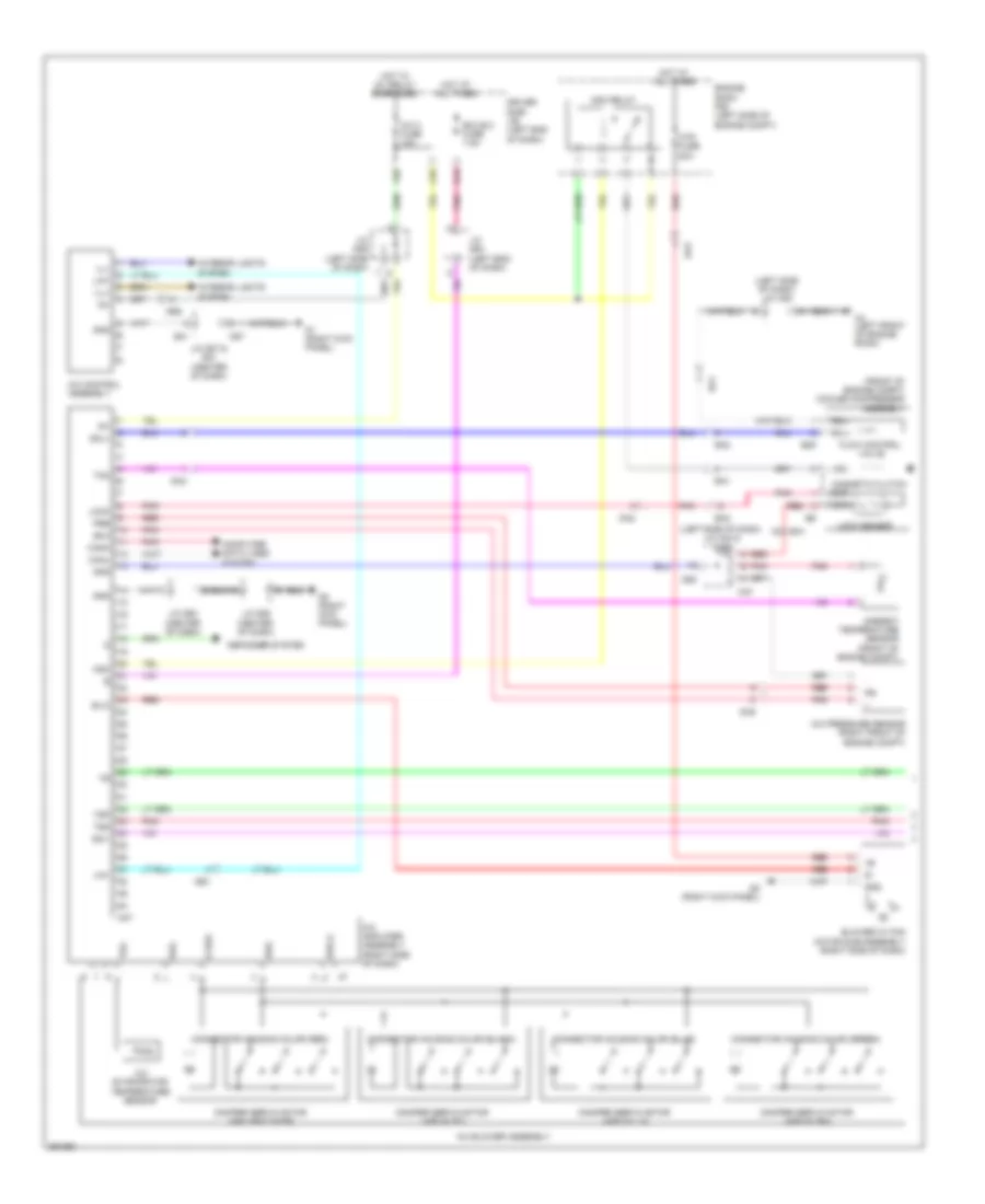
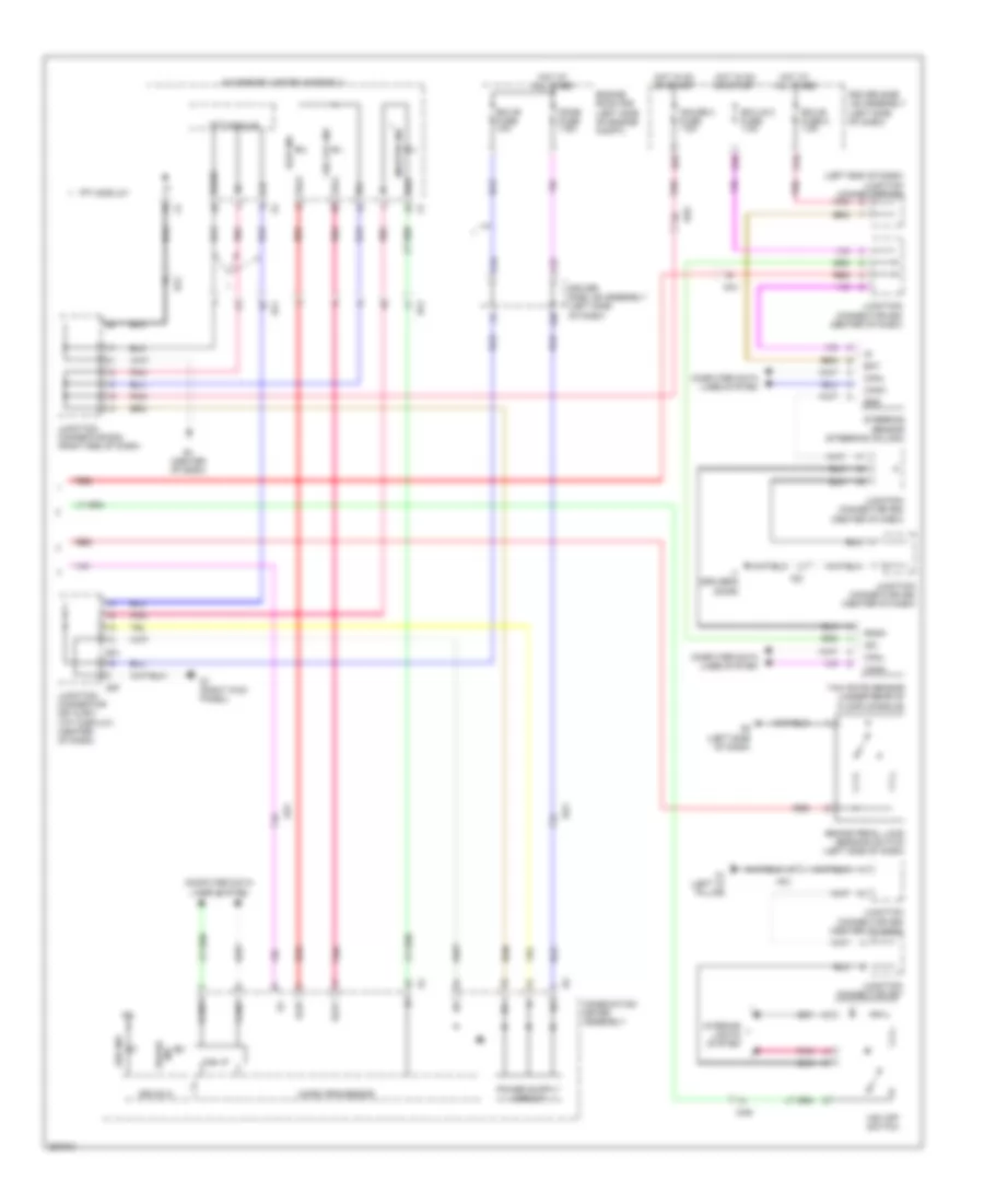
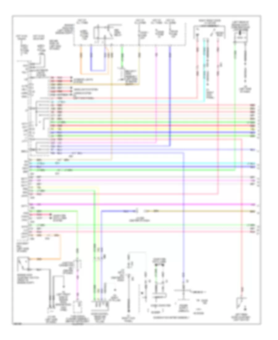
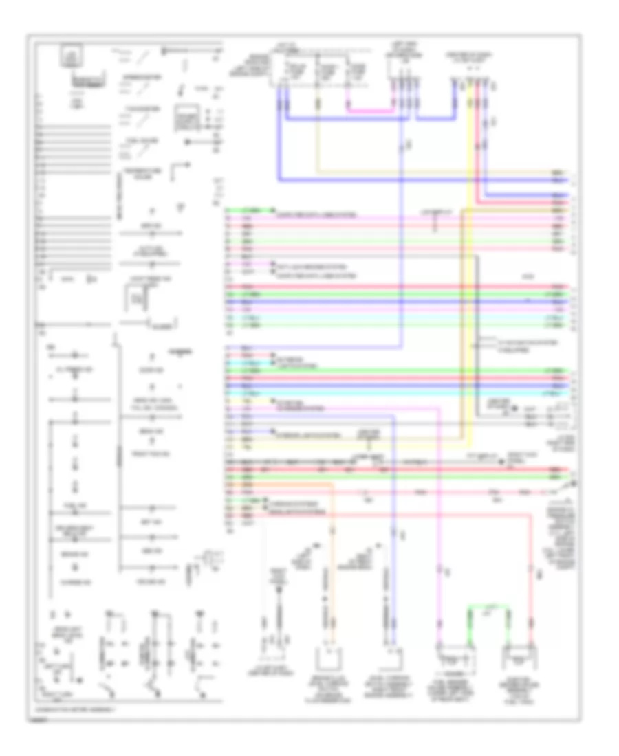
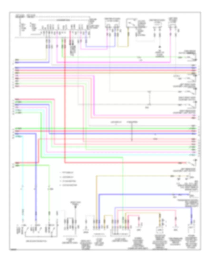
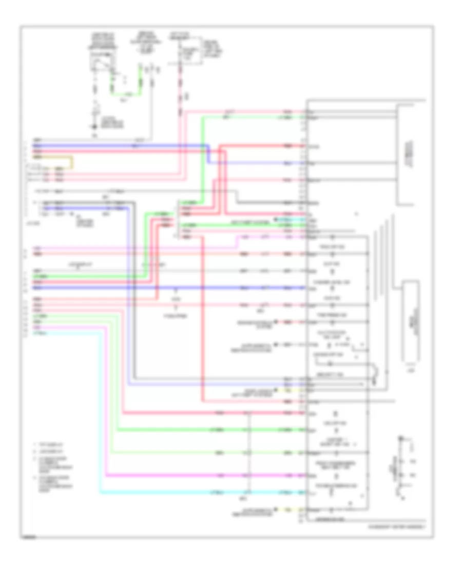
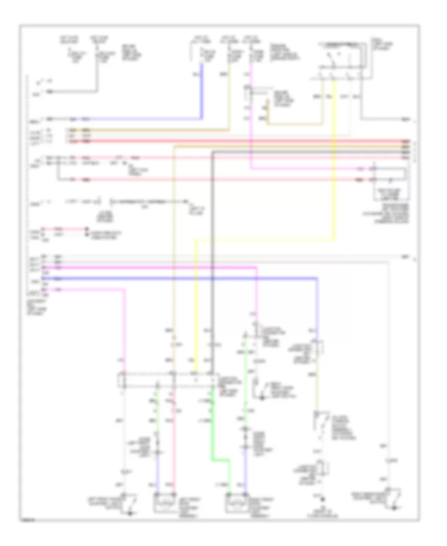
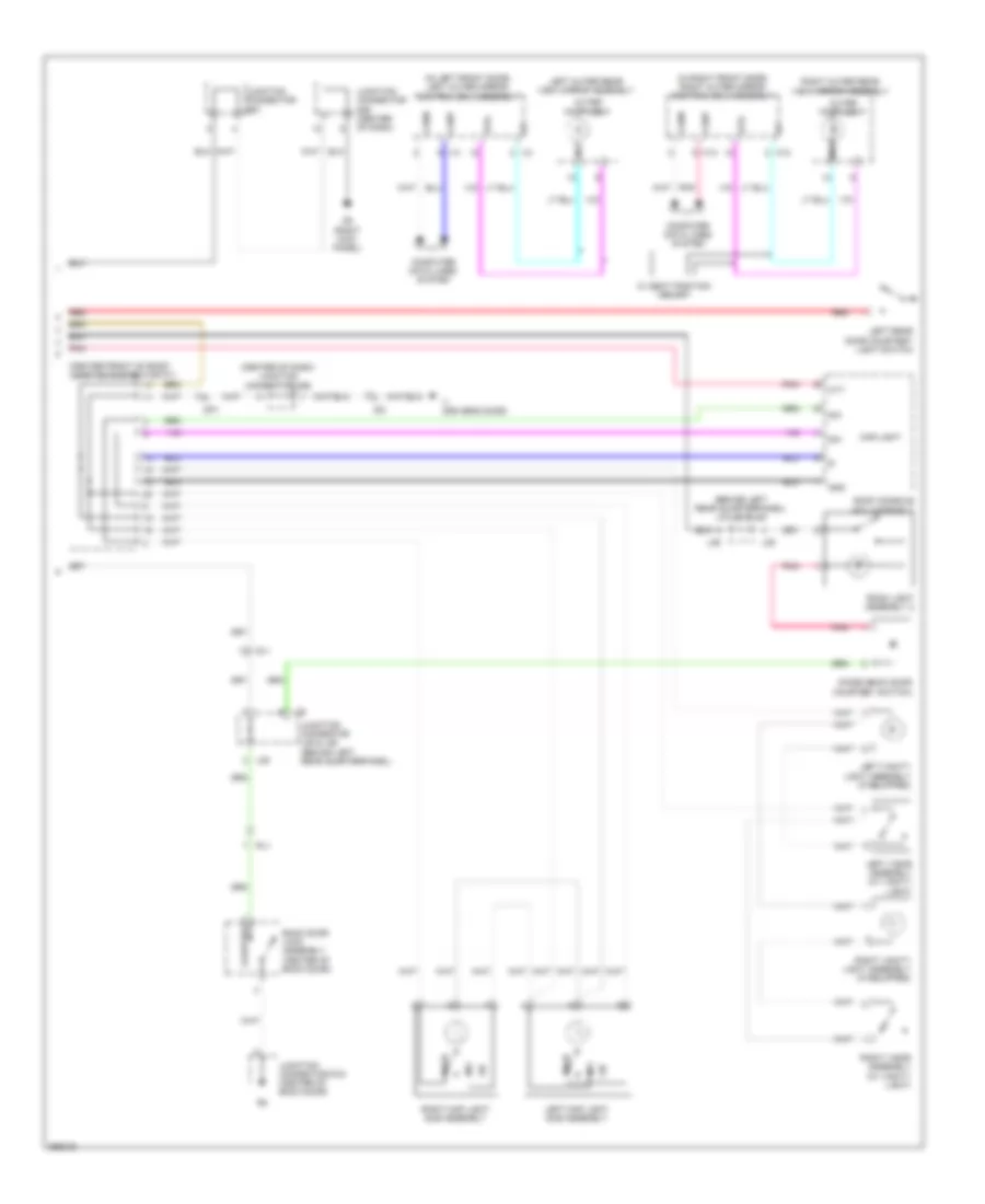
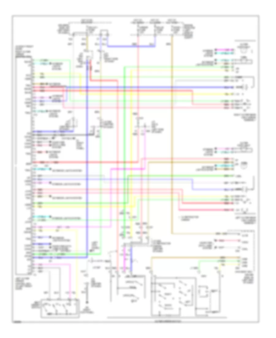
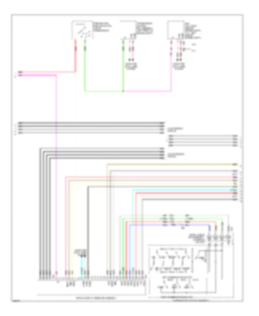
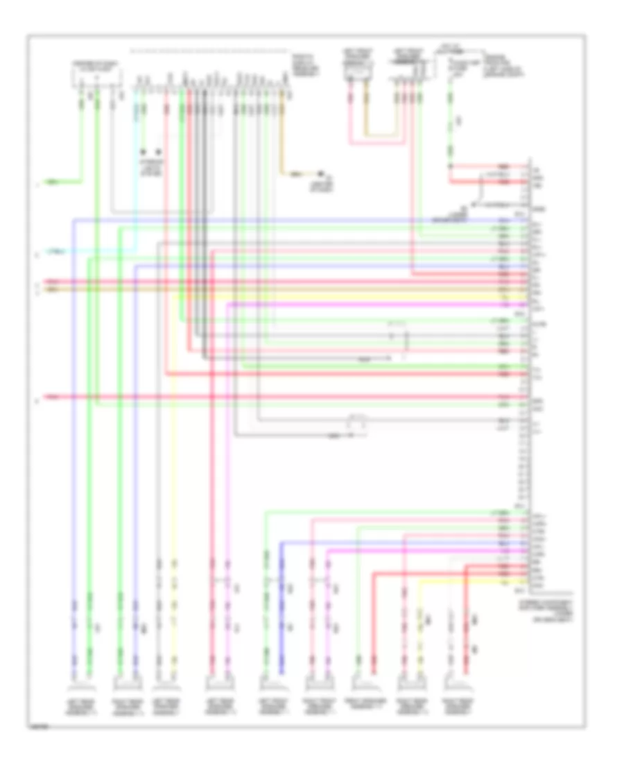
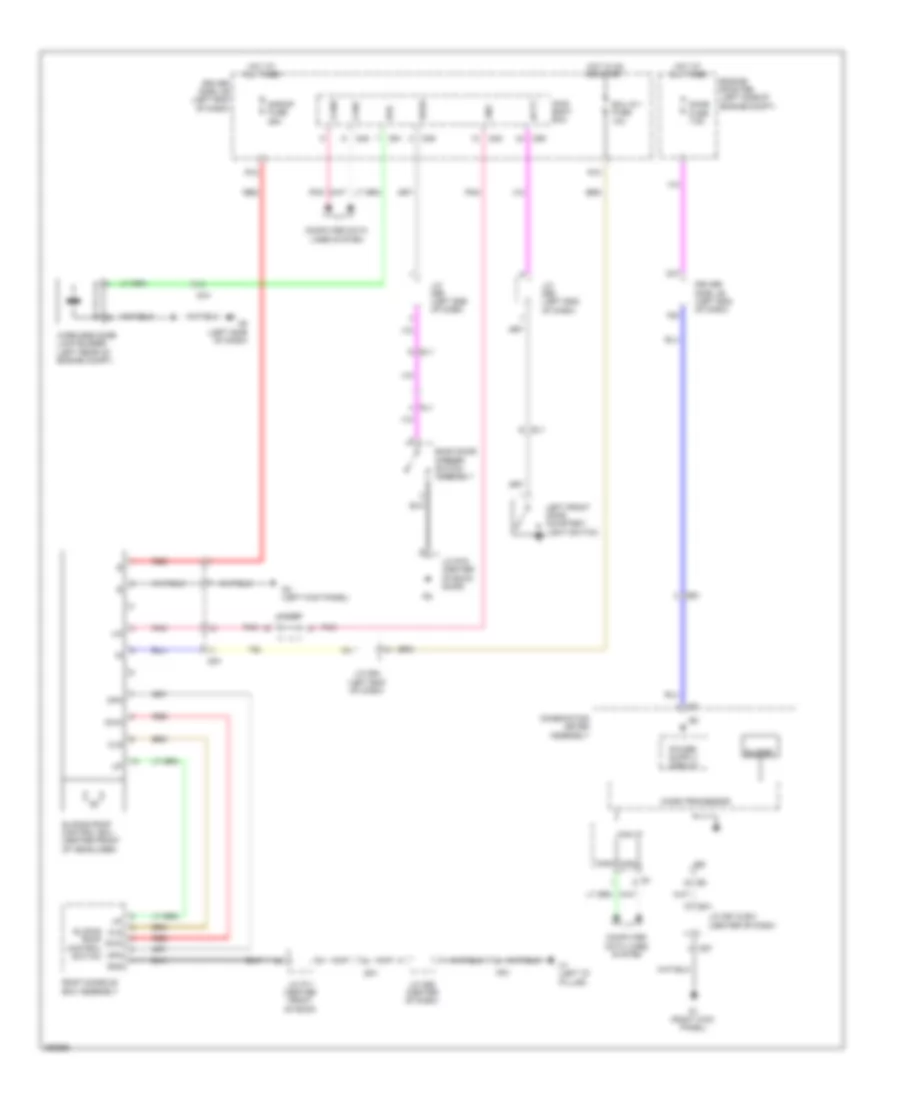
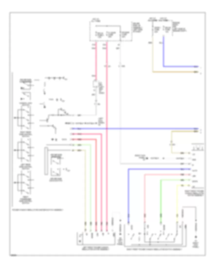
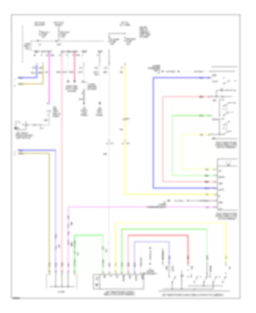
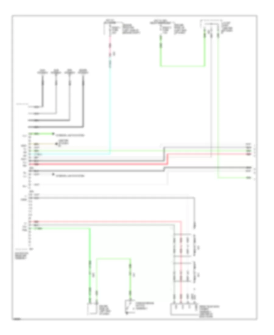
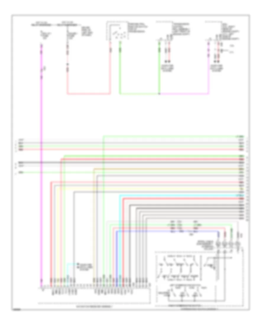
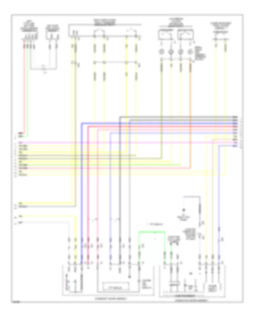
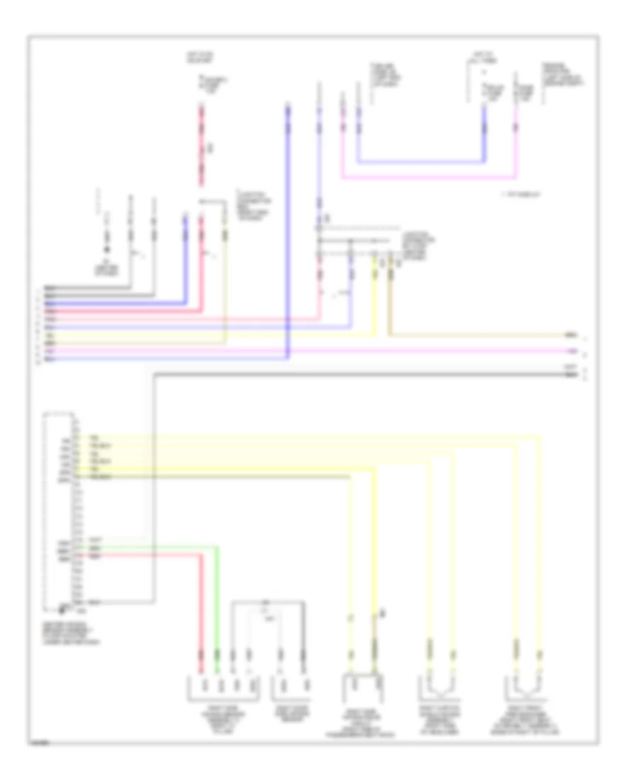
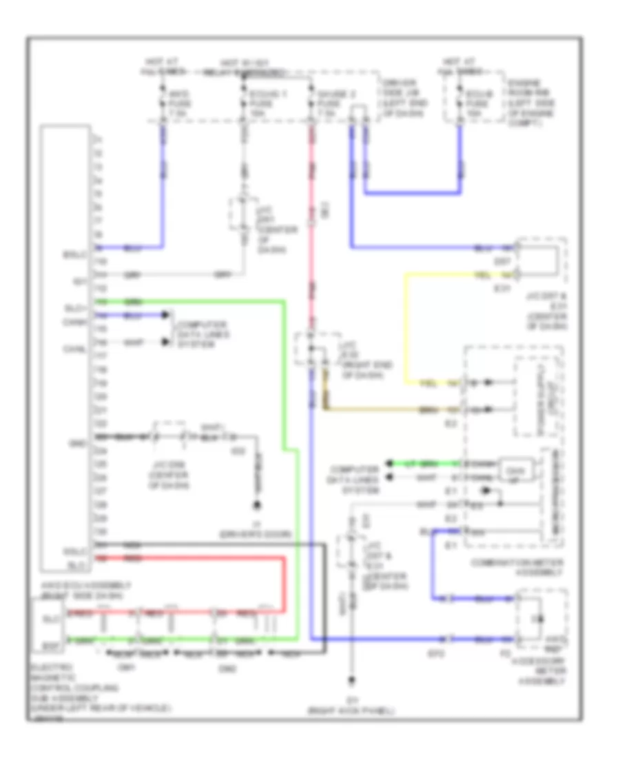
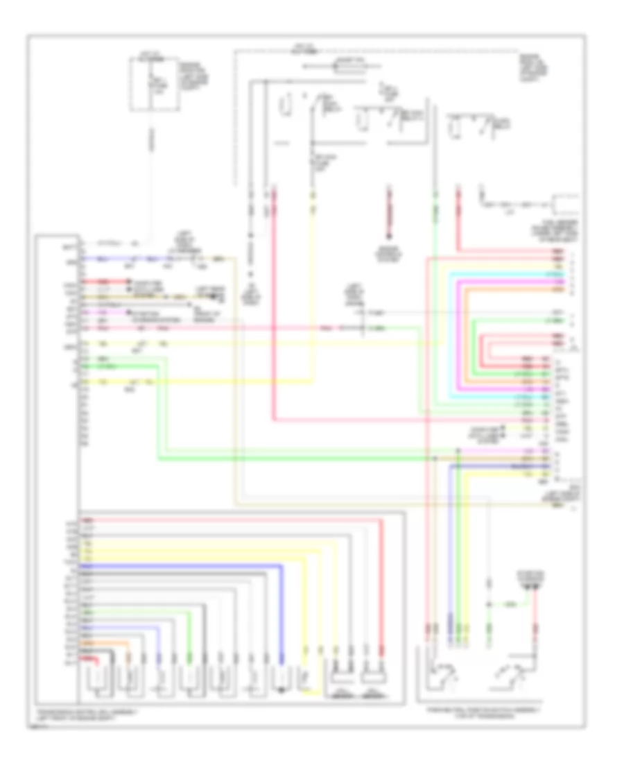
2.7L, Automatic A/C Wiring Diagram (1 of 2) for Toyota Venza LE 2013
 https://portal-diagnostov.com/license.html
Automotive Electricians Portal FZCO
Automotive Electricians Portal FZCO
https://portal-diagnostov.com/license.html
https://portal-diagnostov.com/license.html
Automotive Electricians Portal FZCO
Automotive Electricians Portal FZCO
List of elements for 2.7L, Automatic A/C Wiring Diagram (1 of 2) for Toyota Venza LE 2013:
- (left side of dash) j/c a43 & d55
- (left side of dash) j/c a46
- A/c 2 fuse 10a
- A/c amplifier assembly (right side of dash)
- A/c blower assembly
- A/c control assembly
- A/c evaporator temperature sensor
- A/c pressure sensor (right front of engine compt)
- A4 (left front of engine room)
- A43
- Ambient temperature sensor (front of engine compt)
- B bus
- Ba1
- Ba2
- Blower w/ fan motor sub-assembly (right side of dash)
- Blw
- Bus
- Bus g
- Canh
- Canl
- Computer data lines system
- Connector housing color (black)
- Connector housing color (green)
- Connector housing color (red)
- Cooler compressor assembly (front of engine compt)
- D1 (right kick panel)
- D47
- D5 (right kick panel)
- D55
- D57
- Da2
- Da3
- Da5
- Damper servo motor (air inlet)
- Damper servo motor (air mix lh)
- Damper servo motor (air mix rh)
- Damper servo motor (air vent mode)
- De1
- De2
- Defogger system
- Driver side j/b (left end of dash)
- E31
- Ecu-b 2 fuse 7.5a
- Engine room r/b (left side of engine compt)
- F28
- Flow control valve
- Gnd
- Heater fuse 50a
- Hot at all times
- Hot w/ ig1 relay energized
- Ig+
- Ill+
- Ill-
- Interior lights system
- J/c d55 (left side of dash)
- J/c d57 & e31 (center of dash)
- J/c d58 (center of dash)
- J/c d62 (center of dash)
- J/c d64 (left end of dash)
- K16
- Lin1
- Pnk
- Pre
- Red
- S5-3
- Sg-1
- Sga
- Sol+
- Sol-
- Tam
- Tea
- Tsd
- Tsp
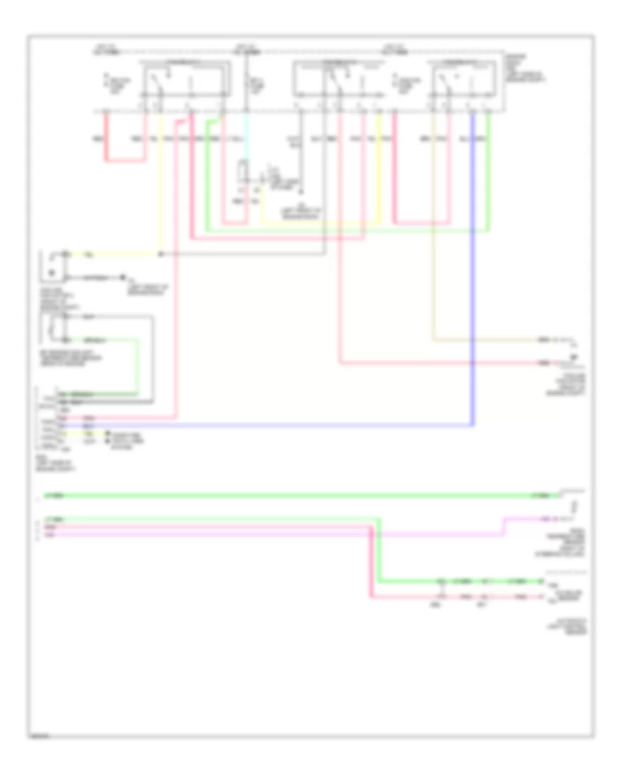
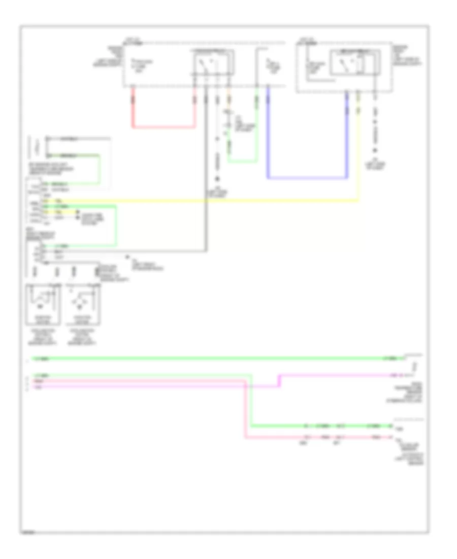
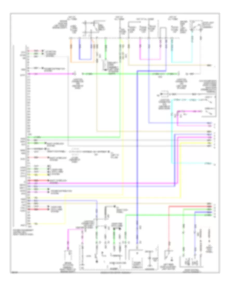
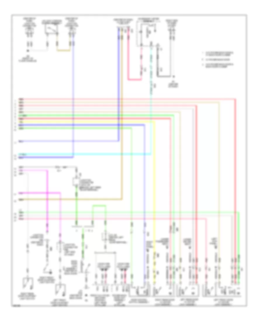
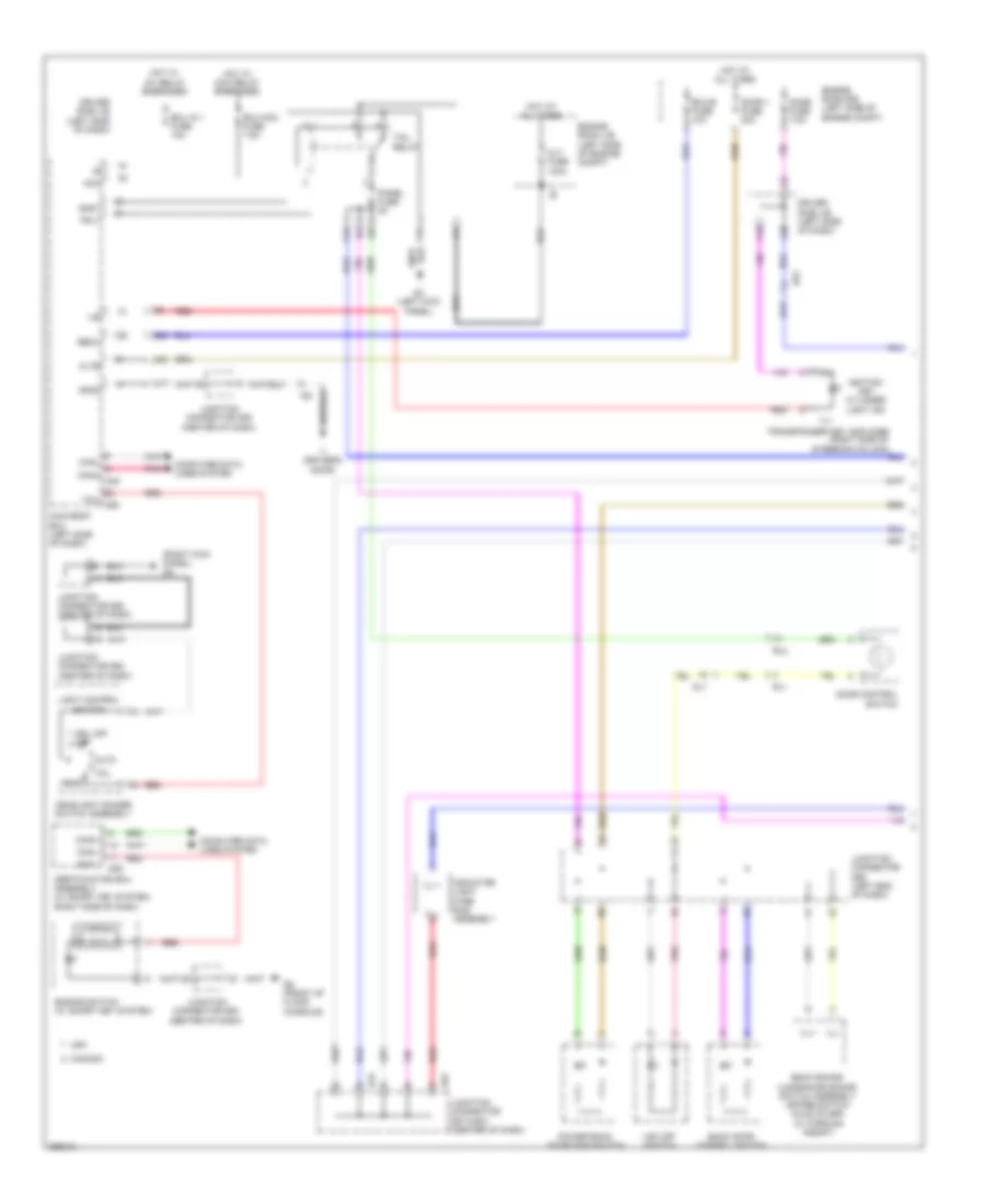
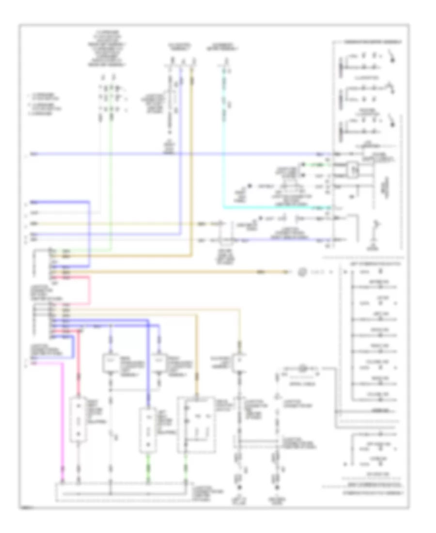
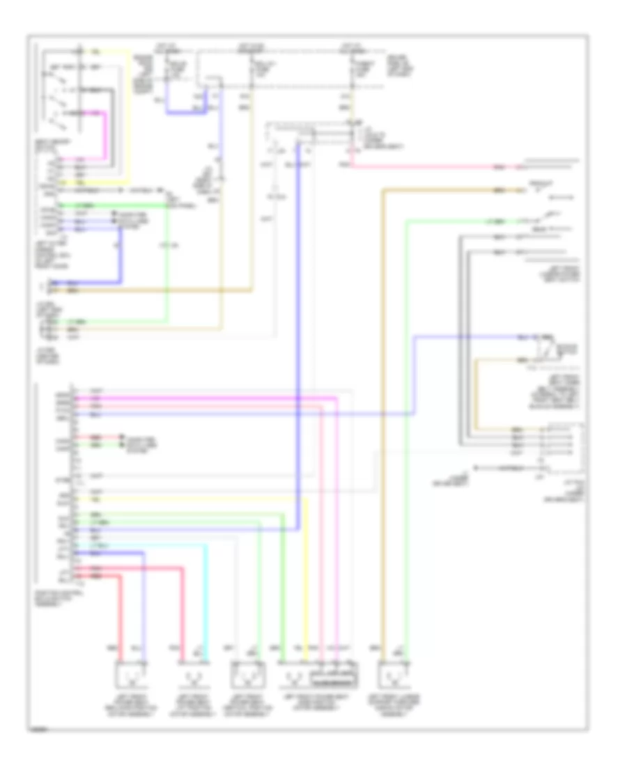
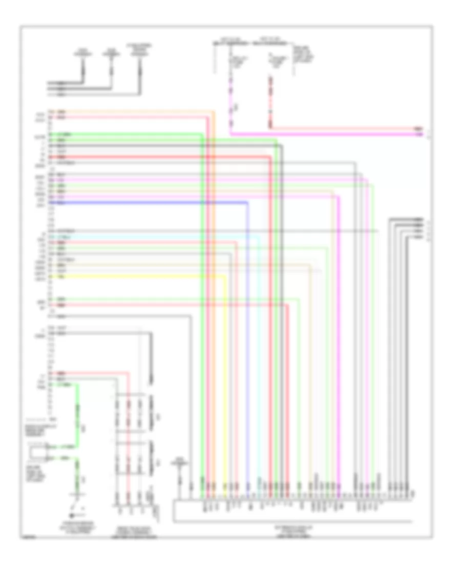
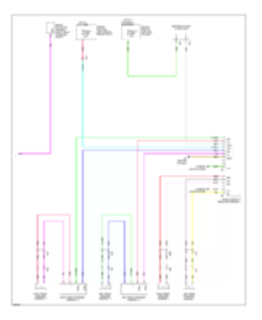
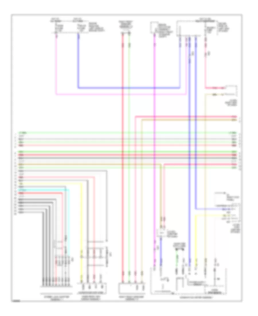
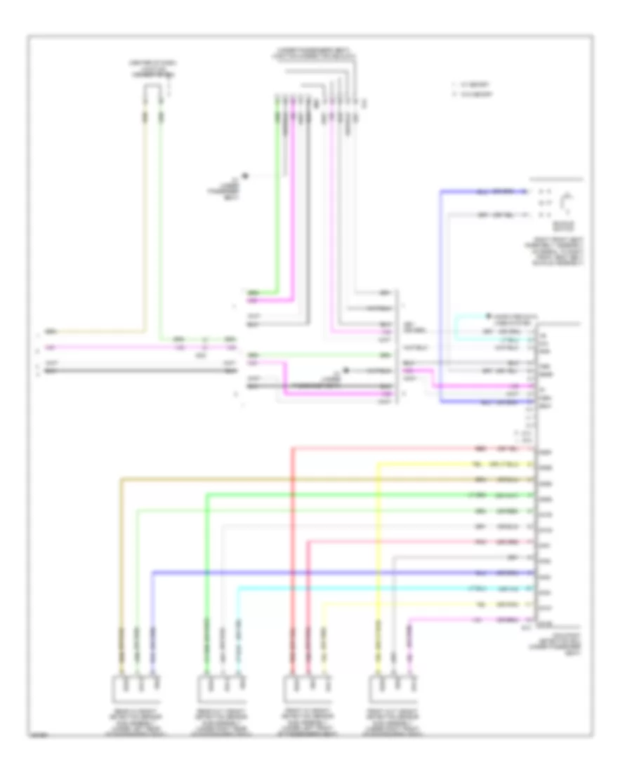
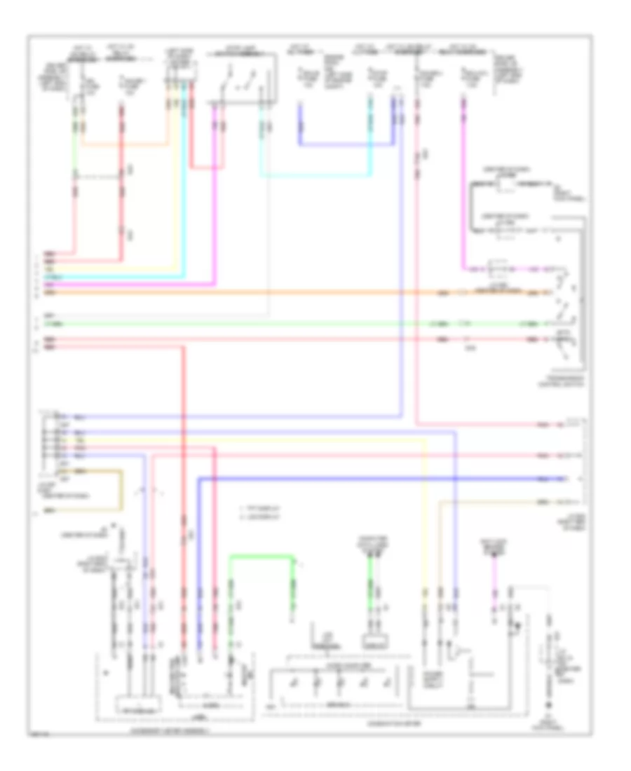
2.7L, Automatic A/C Wiring Diagram (2 of 2) for Toyota Venza LE 2013
List of elements for 2.7L, Automatic A/C Wiring Diagram (2 of 2) for Toyota Venza LE 2013:
- A/c solar sensor
- A4 (left front of engine room)
- A49
- Automatic light control sensor
- B58
- Canh
- Canl
- Cds fan fuse 30a
- Computer
- Cooling fan motor (front of engine compt)
- Cooling fan motor 2 (front of engine compt)
- Data lines
- De2
- Ecm (left side of engine compt)
- Ef1
- Efi 3 fuse 10a
- Efi engine coolant temperature sensor (rear of engine)
- Engine room r/b (left side of engine compt)
- Ethw
- Fan relay 1
- Fan relay 2
- Fan relay 3
- Fanh
- Fanl
- Hot at all times
- J/c a46 (left side of dash)
- Pnk
- Rdi fan fuse 30a
- Red
- Room temperature sensor (right of steering column)
- System
- Thw
- Tsl
- Tsr
3.5L
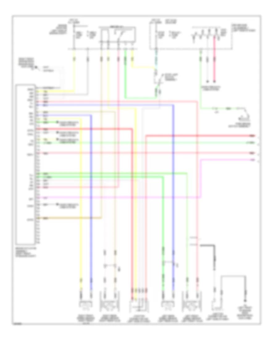
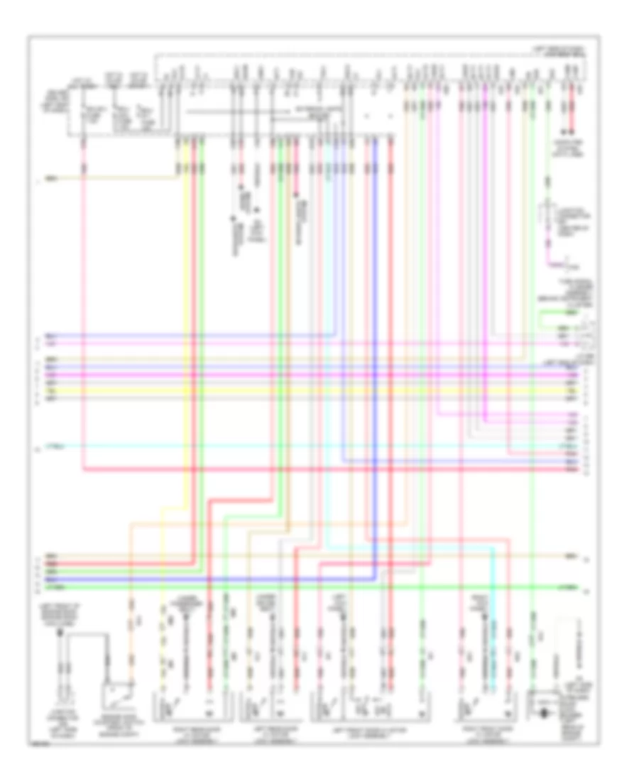
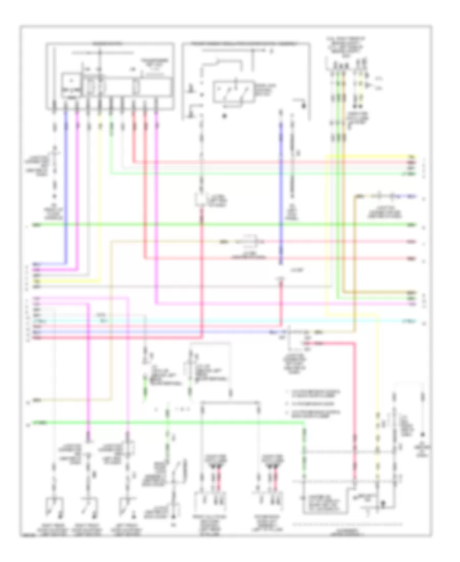
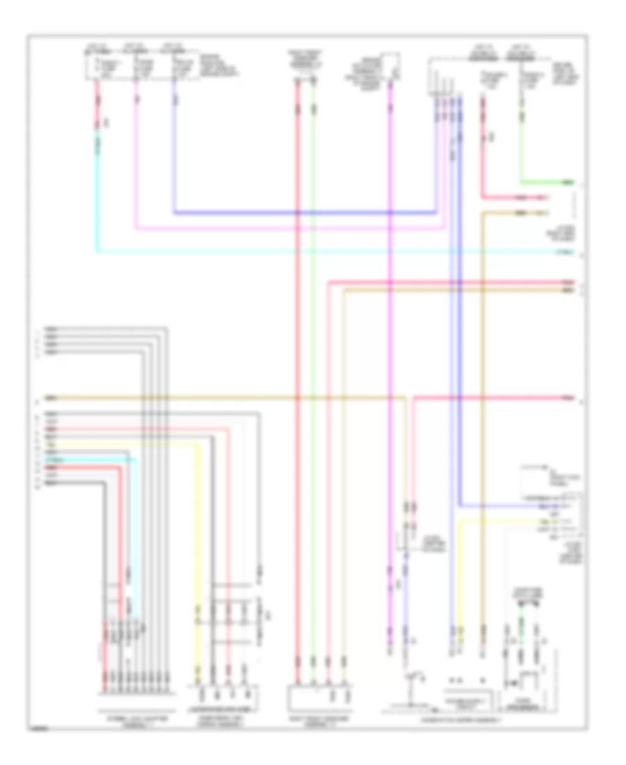
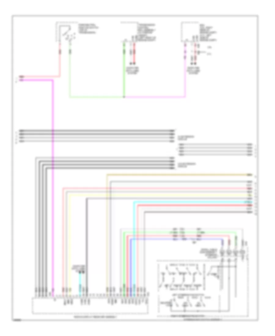
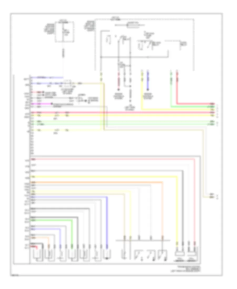
3.5L, Automatic A/C Wiring Diagram (1 of 2) for Toyota Venza LE 2013
List of elements for 3.5L, Automatic A/C Wiring Diagram (1 of 2) for Toyota Venza LE 2013:
- (front of engine compt) cooler compressor assembly
- (left side of dash) j/c a43 & d55
- (left side of dash) j/c a46
- A/c 2 fuse 10a
- A/c amplifier assembly (right side of dash)
- A/c blower assembly
- A/c control assembly
- A/c evaporator temperature sensor
- A/c pressure sensor (right front of engine compt)
- A4 (left front of engine room)
- A43
- Ambient temperature sensor (front of engine compt)
- B bus
- B29
- Ba1
- Ba2
- Blower w/ fan motor sub-assembly (right side of dash)
- Blw
- Bus
- Bus g
- C26
- Canh
- Canl
- Computer data lines system
- Connector housing color (black)
- Connector housing color (green)
- Connector housing color (red)
- D1 (right kick panel)
- D47
- D5 (right kick panel)
- D55
- D57
- Da2
- Da3
- Da5
- Damper servo motor (air inlet)
- Damper servo motor (air mix lh)
- Damper servo motor (air mix rh)
- Damper servo motor (air vent mode)
- De1
- De2
- Defogger system
- Driver side j/b (left end of dash)
- E31
- Ecu-b 2 fuse 7.5a
- Engine room r/b (left side of engine compt)
- F28
- Flow control valve
- Gnd
- Hot at all times
- Hot w/ ig1 relay energized
- Htr fuse 50a
- Ig+
- Ill+
- Ill-
- Interior lights system
- J/c d55 (left side of dash)
- J/c d57 & e31 (center of dash)
- J/c d58 (center of dash)
- J/c d62 (center of dash)
- J/c d64 (left end of dash)
- K16
- Lin1
- Lock
- Lock sensor
- Magnetic clutch
- Mg+
- Mgc
- Mgc relay
- Pnk
- Pre
- Red
- S5-3
- Sg-1
- Sga
- Sol+
- Sol-
- Ssr+
- Ssr-
- Tam
- Tea
- Tsd
- Tsp
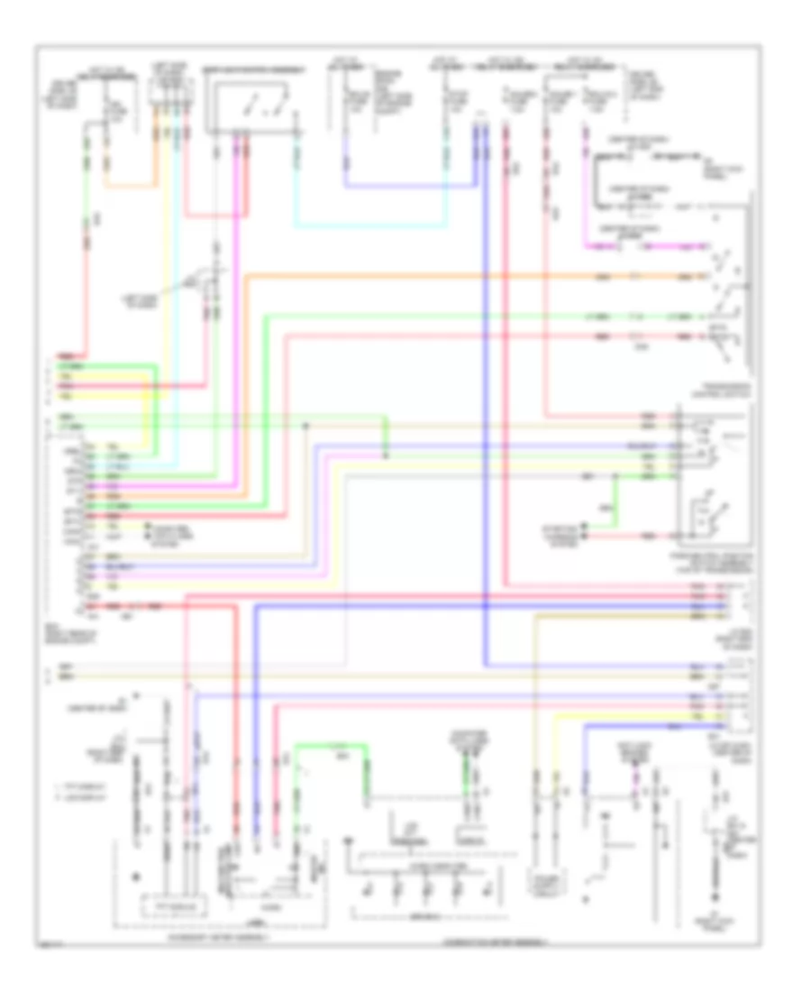
3.5L, Automatic A/C Wiring Diagram (2 of 2) for Toyota Venza LE 2013
List of elements for 3.5L, Automatic A/C Wiring Diagram (2 of 2) for Toyota Venza LE 2013:
- (front of engine compt)
- +b1
- 50a
- A/c solar sensor
- A4 (left front of engine room)
- A41
- A5 (left side of dash)
- Automatic light control sensor
- B39
- Canh
- Canl
- Computer data lines system
- Cooling fan ecu
- Cooling fan motor (front of engine compt)
- Cooling fan motor 2 (front of engine compt)
- De2
- Ecm (right rear of engine compt)
- Ef1
- Efi 3 fuse 10a
- Efi engine coolant temperature sensor (rear of engine)
- Efi main fuse 25a
- Efi main relay
- Engine room j/b (left side of engine compt)
- Engine room r/b (left side of engine compt)
- Ethw
- F12
- Fan main fuse
- Fan main relay
- Hot at all times
- J/c a46 (left side of dash)
- M+(m)
- M+(s)
- M-(m)
- M-(s)
- Main fan motor
- Mrel
- Pnk
- Red
- Rfc
- Room temperature sensor (right of steering column)
- Sub fan motor
- Thw
- Tsl
- Tsr
- Z13
- Z14
ANTI-LOCK BRAKES
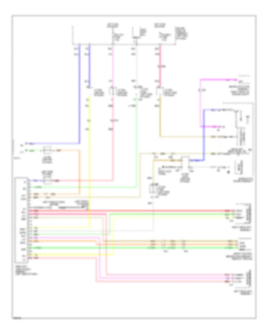
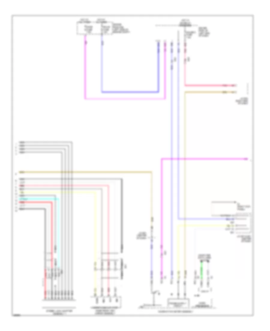
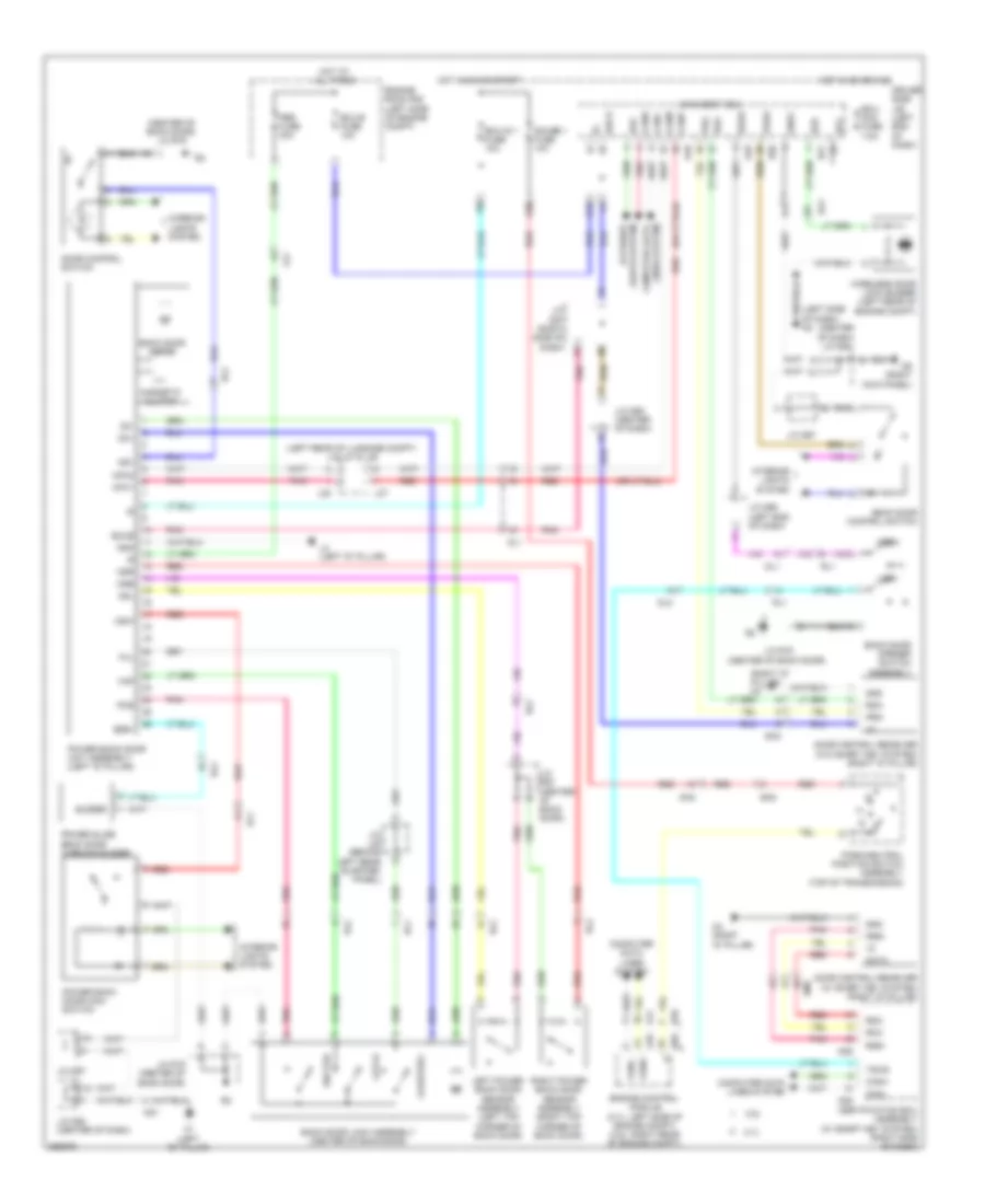
Anti-lock Brakes Wiring Diagram (1 of 2) for Toyota Venza LE 2013
List of elements for Anti-lock Brakes Wiring Diagram (1 of 2) for Toyota Venza LE 2013:
- (right front engine room (engine room main wire)) a1
- +bm
- +bs
- A4 (left front of engine room (engine room main wire))
- Abs 1 fuse 50a
- Abs 2 fuse 30a
- Brake actuator assembly (right front of engine compt)
- Brk relay
- C16
- Canh
- Canl
- Computer data lines system
- Csw
- D/g
- D48
- Driver side j/b assembly (left side of dash)
- Ecu-ig 1 fuse 10a
- Engine room r/b (left side of engine compt)
- Fl+
- Fl-
- Fr+
- Fr-
- Fsw+
- Gnd1
- Gnd2
- Hot at all times
- Hot in on or start
- Ig1
- Junction connector a45 (left side of dash)
- Junction connector a46 (left side of dash)
- La1
- Left front speed sensor (left front axle)
- Left rear speed sensor (left rear axle)
- Ma1
- Main body ecu
- Nca
- Park brake switch assembly
- Pkb
- Pnk
- Red
- Right front speed sensor (right front axle)
- Right rear speed sensor (right rear axle)
- Rl+
- Rl-
- Rr+
- Rr-
- Sp1
- Stop fuse 10a
- Stop lamp switch assembly
- Stp
- Stp2
- Stpo
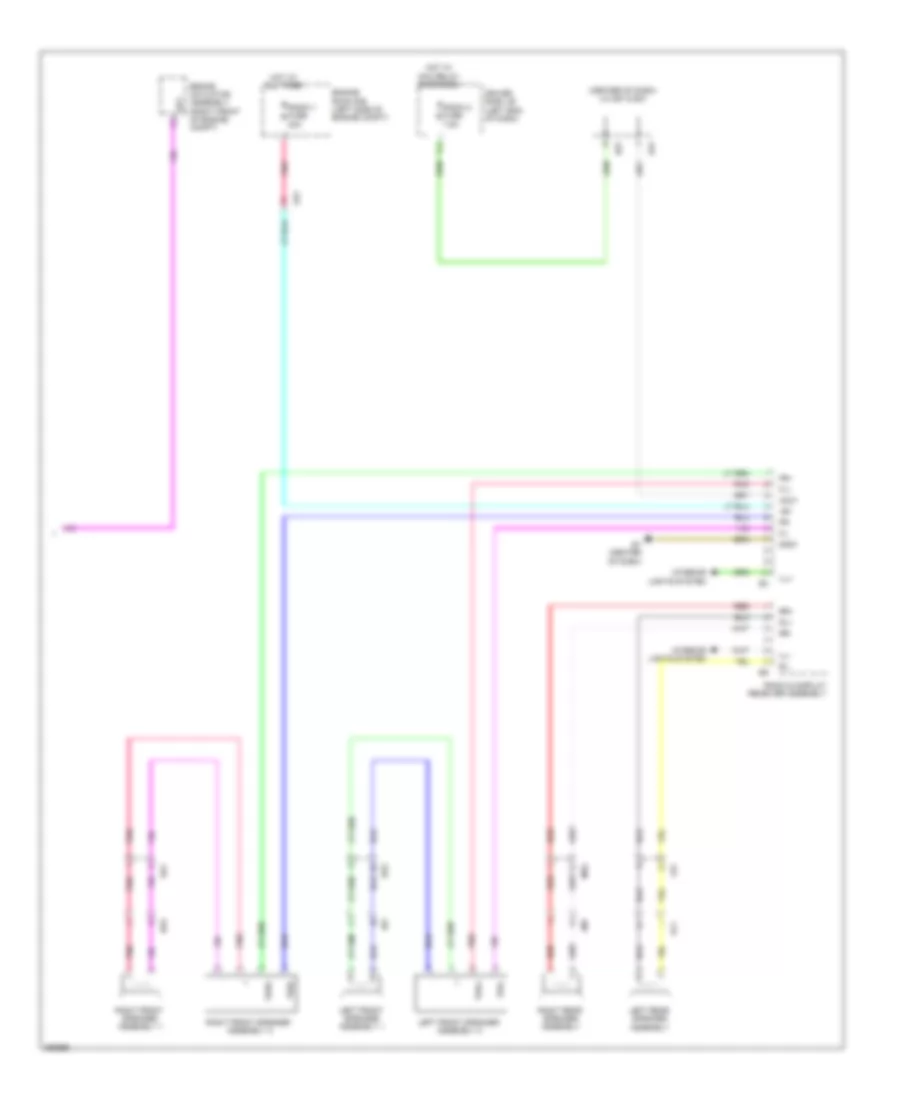
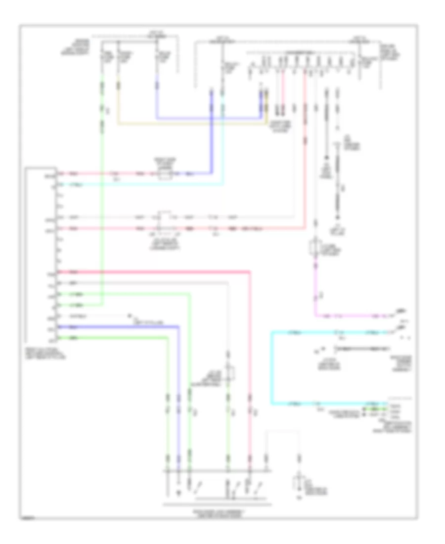
Anti-lock Brakes Wiring Diagram (2 of 2) for Toyota Venza LE 2013
List of elements for Anti-lock Brakes Wiring Diagram (2 of 2) for Toyota Venza LE 2013:
- (left end of dash) junction connector d64
- A5 (left side of dash)
- Abs ind
- Accessory meter assembly
- Ae1
- Bat
- Brake pedal load sensing switch (left side of dash)
- C24
- C27
- Can i/f
- Canh
- Canl
- Combination meter assembly
- Computer data lines system
- D1 (right kick panel)
- D57
- Da1
- Da5
- De1
- De2
- Dome fuse 7.sa
- Drive ic
- Driver side j/b assembly (left side of dash)
- E1 (center of dash)
- E31
- Ecu-b fuse 10a
- Ecu-b fuse 2 7.5a
- Ecu-ig 2 fuse 7.5a
- Ef1
- Ef2
- Engine room r/b (left side of engine compt)
- Ess
- F20
- G25
- Gauge 2 fuse 7.5a
- Gnda
- H1 (left "d" pillar)
- Hd1
- Hot at all times
- Hot in on or start
- I1 (driver's door)
- Id2
- Ig+
- Ig2
- Iga
- Ind brake
- Interior lights system
- Junction connector d57 & e31 (tft display) (center of dash)
- Junction connector d58 (center of dash)
- Junction connector d62 (center of dash)
- Junction connector d63 (center of dash)
- Junction connector d67
- Junction connector e32 (right end of dash)
- K16
- K36
- Master ind
- Micro processor
- Pnk
- Red
- Sg3
- Sg4
- Sg7
- Sgnd
- Slip
- Slip ind
- Slof
- Steering sensor (steering column)
- Tft display
- Tft module
- Vsc off ind
- Vsc off switch
- Yaw rate sensor (under rear of floor console)
ANTI-THEFT
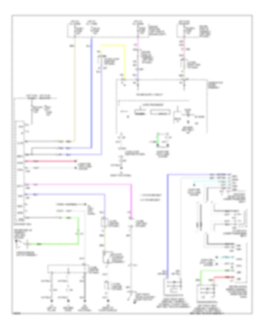
Forced Entry Wiring Diagram, with Smart Key System (1 of 4) for Toyota Venza LE 2013
List of elements for Forced Entry Wiring Diagram, with Smart Key System (1 of 4) for Toyota Venza LE 2013:
- (w/o power back door & back door closer) back door opener switch assembly
- +b (dome)
- Accd
- Ae1
- Am2 fuse 7.5a
- Am21
- Am22
- Brake actuator assembly (right front of engine compt)
- Buzzer
- C16
- C27
- Ca1h
- Ca1l
- Ca2h
- Ca2l
- Ca3n
- Ca3p
- Can i/f
- Canh
- Canl
- Combination meter assembly
- Computer data lines system
- D1 (right kick panel)
- D42
- D43
- D57
- Da1
- Da2
- De1
- Dl1
- Dl2
- Dome fuse 7.5a
- Door 1 fuse 20a
- Door control switch assembly
- Door ind
- Drive ic
- Driver side j/b (left end of dash)
- E31
- Ecu-b fuse 10a
- Engine room r/b (left side of engine compt)
- F20
- Gnd
- Gnd2
- H1 (left "d" pillar)
- Hd1
- Hd2
- Hot at all times
- Ig1d
- Ig2
- Ig2d
- Inds
- Indw
- J/c d58 (center of dash)
- Junction connector a45 (left side of dash)
- Junction connector d57 & e31 (center of dash)
- Junction connector d59 (center of dash)
- Junction connector r19 (center of back door)
- Left rear door courtesy light switch
- Lin2
- Lock
- Lock key
- Lock un- key
- Micro computer
- Open
- Pnk
- Power distribution system
- Power management control ecu (right side of dash)
- Red
- Rl1
- Sec horn relay
- Sec- horn fuse 7.5a
- Security horn assembly (left side of engine compt)
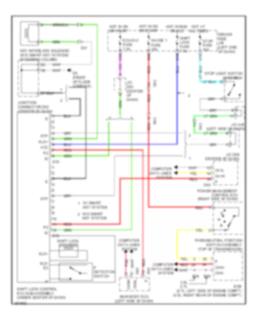
- Shift interlock system
- Slp
- Slr+
- Sp1
- Ssw1
- Ssw2
- Sta
- Star
- Starting/ charging system
- Stop fuse 10a
- Stop light switch assembly
- Stp1
- Sut
Forced Entry Wiring Diagram, with Smart Key System (2 of 4) for Toyota Venza LE 2013
List of elements for Forced Entry Wiring Diagram, with Smart Key System (2 of 4) for Toyota Venza LE 2013:
- (left front of engine room (engine room main wire)) a4
- (left kick panel) d2
- (left side of dash) main body ecu
- (right kick panel) d1
- (under driver seat) l1
- (under passenger seat) m1
- A5 (left side of dash)
- Acc
- Act+
- Act-
- Actd
- Altb
- Bcty
- Bdsu
- Becu
- Bzr
- C24
- C25
- C30
- Cann
- Canp
- Computer system data lines
- D2 (left kick panel)
- D48
- D49
- D50
- D51
- Da1
- Dcty
- Detec- tion
- Dm1
- Dm2
- Driver side j/b (left end of dash)
- Ecu- acc fuse 7.5a
- Ecu- ig 1 fuse 10a
- Ecu-b 2 fuse 7.5a
- Engine hood courtesy switch (front of engine compt)
- Exterior lights system
- F11
- F16
- F30
- G35
- Gnd1
- Haz
- Hcty
- Hd1
- Hd2
- Headlights system
- Horn
- Hot at all times
- Hot in on or acc
- Hot in on or start
- Hrly
- Id1
- Ile
- Interior lights system
- J/c d66 (left end of dash)
- Jm1
- Junction connector a46 (left side of dash)
- Junction connector d61 (center of dash)
- K16
- K26
- Key
- Kl1
- Lcty
- Left front door w/ motor lock assembly
- Left rear door w/ motor lock assembly
- Lin2
- Lock key
- Lock un-
- Lsr
- Lswd
- Lswp
- O17
- O19
- Pcty
- Pnk
- Rcty
- Red
- Right front door w/ motor lock assembly
- Right rear door w/ motor lock assembly
- System horns
- Tion detec-
- Trly
- Turn signal flasher assembly (behind instrument cluster)
- Ul1
- Ul3
- Wireless door lock buzzer (left rear of engine compt)
Forced Entry Wiring Diagram, with Smart Key System (3 of 4) for Toyota Venza LE 2013
List of elements for Forced Entry Wiring Diagram, with Smart Key System (3 of 4) for Toyota Venza LE 2013:
- (3.5l: right rear of engine compt) (2.7l: left side of engine compt) ecm
- 12v
- 2.7l
- 3.5l
- A41
- A49
- Accessory meter assembly
- Agnd
- Back door lock assembly (center of back door)
- Canh
- Canl
- Code
- Computer data lines system
- Courtesy
- D2 (left kick panel)
- D57
- D6 (front of floor console)
- Da5
- De2
- Dl1
- Dm2
- Door lock control switch
- E1 (center of dash)
- E31
- Ef2
- Engine switch
- Front multiplex network door ecu (left rear "d" pillar)
- Full
- Gnd
- Id2
- Imi
- Imo
- Inds
- Indw
- J/c d60 (center of dash)
- J/c d64 (left end of dash)
- J/c d67
- J/c e32 (right end of dash)
- J/c l25 & l26 (behind left rear l25
- J/c l25 (behind left rear quarterpanel) l25
- J/c r19 (center of back door)
- Junction connector d57 & e31 (center of dash)
- Junction connector d59 (center of dash)
- Junction connector d60 (center of dash)
- Junction connector d63 (center of dash)
- Junction connector d66 (left end of dash)
- L26
- Left front door courtesy light switch
- Lin1
- Master ind (w/ tft display) smart key ind (w/ lcd display)
- Mpx1
- Mpx2
- Neo
- Pnk
- Power back door unit assembly (left "d" pillar)
- Power window regulator master switch assembly
- Quarterpanel)
- Red
- Right front door courtesy light switch
- Right rear door courtesy light switch
- Rl1
- Security ind
- Ss1
- Ss2
- Swl
- Transponder key coil
- Txct
- Vc5
- W/ power back door
- W/o power back door & back door closer
- W/o power back door & w/ back door closer
Forced Entry Wiring Diagram, with Smart Key System (4 of 4) for Toyota Venza LE 2013
List of elements for Forced Entry Wiring Diagram, with Smart Key System (4 of 4) for Toyota Venza LE 2013:
- (front of floor console) d6
- (left side of dash) junction connector a43 & d55
- (under rear of floor console) front indoor electrical key oscillator
- A43
- Agnd
- Ant1
- Ant2
- Canh
- Canl
- Certification ecu assembly (right side of dash)
- Cg1b
- Cg2b
- Cg5b
- Cg6b
- Cg7b
- Cg8b
- Clg1
- Clg2
- Clg3
- Clg4
- Clg5
- Clg6
- Clg7
- Clg8
- Clgb
- Code
- Computer data lines system
- Cutb
- D1 (right kick panel)
- D2 (left kick panel)
- D25
- D26
- D55
- Data
- Dl2
- Dm2
- Door control receiver (right "d" pillar)
- Driver side j/b (left end of dash)
- Efi 1 fuse 10a
- Efii
- Efio
- Engine room r/b (left side of engine compt)
- G22
- Gnd
- Hd2
- Hot at all times
- Hot in on or start
- Hz1
- Id2
- Ign fuse 10a
- Indoor luggage compartment electrical key oscillator
- Inds
- Iz1
- Junction connector d63 (center of dash)
- Left front door electrical key oscillator (in left front front door)
- Lin
- M3 (right "d" pillar)
- Outside luggage electrical key antenna
- Pnk
- Pos1
- Pos2
- Rco
- Rda
- Rear indoor electrical key oscillator
- Red
- Right front door electrical key oscillator (in right front front door)
- Rssi
- Sen1
- Sen2
- Sens
- Swil
- Trg+
- Tsw1
- Tsw2
- Tsw5
- Tsw6
- Txct
- Vc5
Forced Entry Wiring Diagram, without Smart Key System (1 of 2) for Toyota Venza LE 2013
List of elements for Forced Entry Wiring Diagram, without Smart Key System (1 of 2) for Toyota Venza LE 2013:
- (left rear of engine compt) wireless door lock buzzer
- +b (dome)
- A4 (left front side of engine room (engine room main wire))
- A5 (left side of dash)
- Acc
- Act+
- Act-
- Actd
- Altb
- Bcty
- Becu
- Buzzer
- Bzr
- C24
- C25
- C27
- C30
- Can i/f
- Canh
- Canl
- Combination meter assembly
- Computer data lines system
- D1 (right kick panel)
- D48
- D49
- D50
- D51
- D57
- Da1
- Da2
- Dcty
- De1
- Detec- tion
- Dm2
- Dome fuse 1a
- Door 1 fuse 20a
- Door control receiver (right "d" pillar)
- Door ind
- Drive ic
- Driver side j/b (left end of dash)
- E31
- Ecu- acc fuse 7.5a
- Ecu- ig 1 fuse 10a
- Ecu-b fuse 10a
- Engine hood courtesy switch (front of engine compt)
- Engine room r/b (left side of engine compt)
- Exterior lights system
- F11
- F16
- F20
- F30
- G35
- Gnd
- Gnd1
- Haz
- Hcty
- Hd1
- Hd2
- Headlights system
- Horn
- Horns system d2 (left kick panel)
- Hot at all times
- Hot in on or acc
- Hot in on or start
- Hrly
- Ile
- Ind
- Interior lights system
- J/c a46 (left side of dash)
- J/c d57 & e31 (center of dash)
- J/c d59 (center of dash)
- Junction connector d61 (center of dash)
- K26
- Ksw
- Lcty
- Left rear door courtesy light switch
- Lsr
- Lswd
- Lswp
- M3 (right "d" pillar)
- Main body ecu (left side of dash)
- Micro computer
- O17
- O19
- Pcty
- Pnk
- Prg
- Rcty
- Rda
- Red
- Right front door w/ motor lock assembly
- Sec horn relay
- Sec- horn fuse 7.5a
- Security horn assembly (left side of engine compt)
- Trly
- Turn signal flasher assembly (behind instrument cluster)
- Ul1
- Ul3
Forced Entry Wiring Diagram, without Smart Key System (2 of 2) for Toyota Venza LE 2013
List of elements for Forced Entry Wiring Diagram, without Smart Key System (2 of 2) for Toyota Venza LE 2013:
- (center of dash) j/c d57 & e31
- (center of dash) junction connector d61
- (center of dash) junction connector d63
- (left kick panel) d2
- (right end of dash) j/c e32
- (right kick panel) d1
- (under driver seat) l1
- (under passenger seat) m1
- Accessory meter assembly
- Back door lock assembly (center of back door)
- Computer data lines system
- Courtesy
- D57
- D6 (front of floor console)
- De2
- Detec- tion
- Dl1
- Dm1
- Dm2
- Door control switch assembly
- E1 (center of dash)
- E31
- Ef1
- Ef2
- Front multiplex network door ecu (left rear "d" pillar)
- Full
- Hd2
- Id1
- J/c l25 (behind left rear quarterpanel)
- J/c r19 (center of back door)
- Jm1
- Junction connector d60 (center of dash)
- Junction connector d66 (left end of dash)
- Junction connector l25 & l26 (behind left rear l25 quarterpanel)
- Key lock
- Key un- lock
- Kl1
- L26
- Left front door courtesy light switch
- Left front door w/ motor lock assembly
- Left rear door w/ motor
- Lock
- Lock assembly
- Mpx1
- Mpx2
- Pnk
- Power back door unit assembly (left "d" pillar)
- Red
- Right front door courtesy light switch
- Right rear door courtesy light switch
- Right rear door w/ motor
- Rl1
- Sec
- Security ind
- Tion detec-
- Un- lock
- Un-lock warning switch assembly
- W/ power back door
- W/o power back door & back door closer
- W/o power back door & w/ back door closer
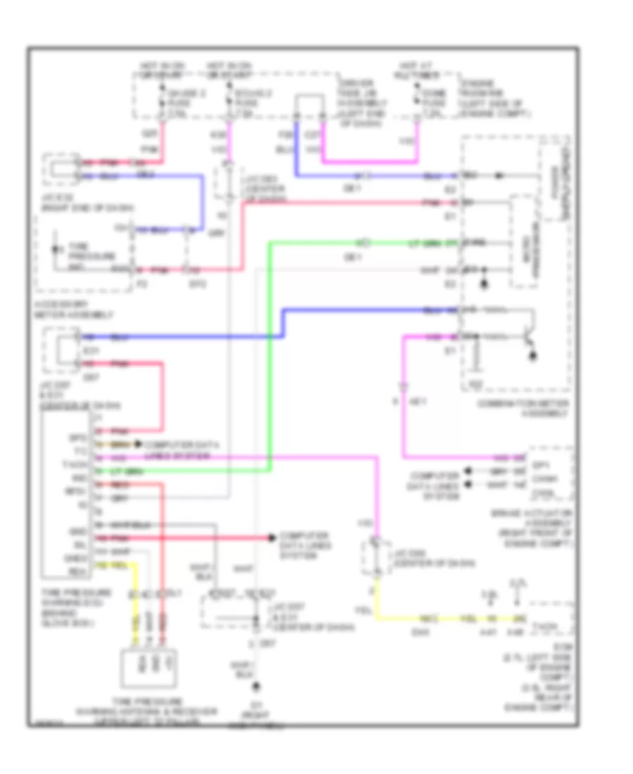
Immobilizer Wiring Diagram, with Smart Key System for Toyota Venza LE 2013
List of elements for Immobilizer Wiring Diagram, with Smart Key System for Toyota Venza LE 2013:
- (left side of dash) a5
- (left side of dash) j/c a46
- 2.7l
- 3.5l
- A41
- A49
- Accessory meter assembly
- Ae1
- Agnd
- B1 (top of engine (sensor wire))
- B39
- Batt
- Brake actuator assembly (right front of engine compt)
- Buzzer
- C24
- C27
- Ca1h
- Ca1l
- Can i/f
- Canh
- Canl
- Certification ecu assembly (right side of dash)
- Code
- Combination meter assembly
- Computer data lines system
- Cutb
- D1 (right kick panel)
- D25
- D43
- D57
- D6 (front of floor console)
- Da5
- De1
- De2
- Dome fuse 7.5a
- Driver's side j/b (left end of dash)
- E01
- E1 (center of dash)
- E31
- Ecm (2.7l: left side of engine compt) (3.5l: right rear of engine compt)
- Ecu-b fuse 10a
- Ef1
- Ef2
- Efi 1 fuse 10a
- Efii
- Efio
- Engine room r/b (left side of engine compt)
- Engine switch
- F20
- Gnd
- Hot at all times
- Ig2
- Imi
- Imo
- Inds
- J/c a43 (left side of dash)
- J/c d57 & e31 (center of dash)
- J/c d59 (center of dash)
- J/c d63 (center of dash)
- J/c e32 (right end of dash)
- Key coil transponder
- Master ind (w/ tft display) smart key ind (w/ lcd display)
- Micro processor
- Pnk
- Power management control ecu (right side of dash)
- Red
- Security ind
- Sg7
- Sgnd
- Sp1
- Sut
- Tft display
- Tft module
- Txct
- Vc5
Immobilizer Wiring Diagram, without Smart Key System for Toyota Venza LE 2013
List of elements for Immobilizer Wiring Diagram, without Smart Key System for Toyota Venza LE 2013:
- (center of dash) junction connector d57 & e31
- 2.7l
- 3.5l
- A41
- A43
- A49
- Accessory meter assembly
- Agnd
- Ant1
- Ant2
- C24
- Code
- Computer data lines system
- Cty
- D55
- D57
- D6 (front of floor console)
- Da5
- De2
- Dl1
- Driver's side j/b (left end of dash)
- E1 (center of dash)
- E31
- Ecm (2.7l: left side of engine compt) (3.5l: right rear of engine compt)
- Ecu-b fuse 10a
- Ef1
- Ef2
- Efi 1 fuse 10a
- Efii
- Efio
- Engine room r/b (left side of engine compt)
- G22
- Gnd
- Hot at all times
- Hot in on or start
- Ign fuse 10a
- Ill+
- Ill-
- Imi
- Imo
- Ind
- Interior lights system
- Junction connector a43 & d55 (left side of dash)
- Junction connector d61 (center of dash)
- Junction connector d63 (center of dash)
- Junction connector d66 (left end of dash)
- Junction connector e32 (right end of dash)
- Ksw
- Left front door courtesy light switch
- Pnk
- Red
- Security ind
- Transponder key amplifier (right side of steering column)
- Transponder key coil
- Transponder key ecu assembly (above steering column)
- Txct
- Unlock warning switch assembly
- Vc5
BODY CONTROL MODULES
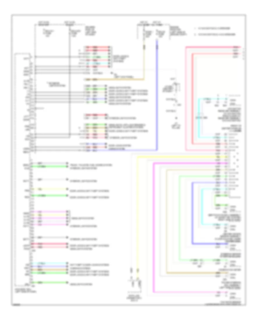
Body Control Modules Wiring Diagram (1 of 2) for Toyota Venza LE 2013
List of elements for Body Control Modules Wiring Diagram (1 of 2) for Toyota Venza LE 2013:
- (front of center console) j/c d68
- Acc
- Act+
- Act-
- Altb
- Anti-theft & door locks systems
- Bcty
- Bdsu
- Becu
- Bzr
- C23
- C24
- C25
- C30
- Canh
- Canl
- Center air bag sensor assembly (floor mounted under center dash)
- Certification ecu assembly (w/ smart key system) (right side of dash)
- Cltb
- Clte
- Clts
- Combination meter
- D2 (left kick panel)
- D20
- D25
- D49
- D51
- Data link connector 3 (dlc 3)
- De1
- De2
- Dim
- Domr
- Door 1 fuse 20a
- Door locks & anti-theft systems
- Door locks system
- Driver's side j/b (left end of dash)
- Drl
- E40
- E42
- Ecu-acc fuse 7.5a
- Ecu-b fuse 10a
- Ecu-ig 1 fuse 10a
- Engine room r/b (left side of engine compt)
- Exterior lights system
- F11
- F16
- F30
- Ffog
- G35
- Gnd1
- Gnd2
- H1 (left "d" pillar)
- Hd1
- Head
- Headlights system
- Headlights, anti-lock brakes & instrument cluster systems
- Horn
- Horns system
- Hot at all times
- Hot in on or acc
- Hot in on or start
- Hrly
- Ile
- Ind
- Interior lights system
- J/c d58 (center of dash)
- K17
- K26
- Ksw
- Lcty
- Lsr
- Lswp
- Main body ecu (left side of dash)
- Mile
- Navigation receiver assembly (w/ navigation) radio & display receiver assembly (w/o navigation)
- O17
- O19
- Pcty
- Pkb
- Pnk
- Power steering ecu assembly (left side of dash)
- Prg
- Rcty
- Rda
- Red
- Steering sensor (steering column)
- Trly
- Trunk, tailgate, fuel doors system
- Ul1
- W/ navigation & 13 speaker
- W/o navigation & 13 & 6 speaker
- Warning systems
- Yaw rate sensor (under rear of floor console)
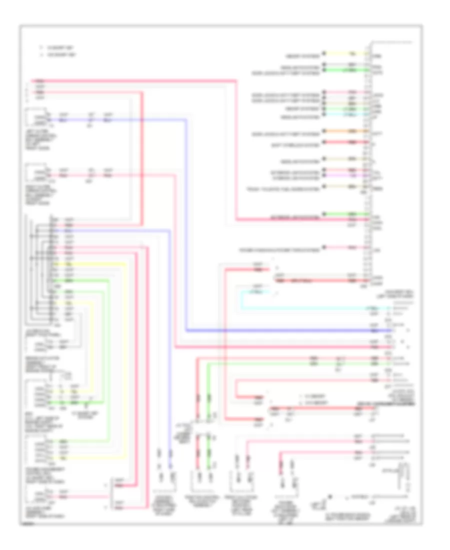
Body Control Modules Wiring Diagram (2 of 2) for Toyota Venza LE 2013
List of elements for Body Control Modules Wiring Diagram (2 of 2) for Toyota Venza LE 2013:
- 3.5l 2.7l
- A/c amplifier assembly (right side of dash)
- A41
- A44
- A49
- Actd
- Awd ecu assembly (if equipped) (right side of dash)
- Brake actuator assembly (right front of engine compt)
- Ca1h
- Ca1l
- Ca3n
- Ca3p
- Canh
- Canl
- Cann
- Canp
- D43
- D47
- D48
- D50
- D56
- D73
- D74
- D75
- D76
- D77
- Dcty
- Dl1
- Door locks & anti-theft systems
- Ecm (2.7l: left side of engine compt) (3.5l: right rear of engine compt)
- Exterior lights system
- Ffgo
- Front multiplex network door ecu (left rear "d" pillar)
- H13
- Haz
- Hcty
- Hd1
- Headlights system
- I13
- Id1
- Interior lights system
- J/c d56 & a44 (right kick panel)
- J/c d73, d74, d75, d76 & d77 (w/ memory) (behind instrument cluster)
- J/c l27, l28, l29 & l30 (left rear of luggage compt)
- J/c t9 & l24 (under driver's seat)
- L2 (left "d" pillar)
- L24
- L27
- L28
- L29
- L30
- Left outer mirror control ecu assembly (in left front door)
- Lin2
- Lswd
- Main body ecu (left side of dash)
- Memory systems
- Mirb
- Mire
- Mirs
- Mpx1
- Mpx2
- Pbds
- Pnk
- Position control ecu & switch assembly
- Power back door unit assembly (if equipped) (left "d" pillar)
- Power management control ecu (w/ smart key) (right side of dash)
- Power windows & power tops systems
- Red
- Right outer mirror control ecu assembly (in right front door)
- Shift interlock system
- St-plug
- T11
- Tail
- Trunk, tailgate, fuel doors system
- Ul3
- W/ memory
- W/ power back door & seat position memory
- W/ smart key
- W/ smart key system
- W/o memory
- W/o smart key
COMPUTER DATA LINES
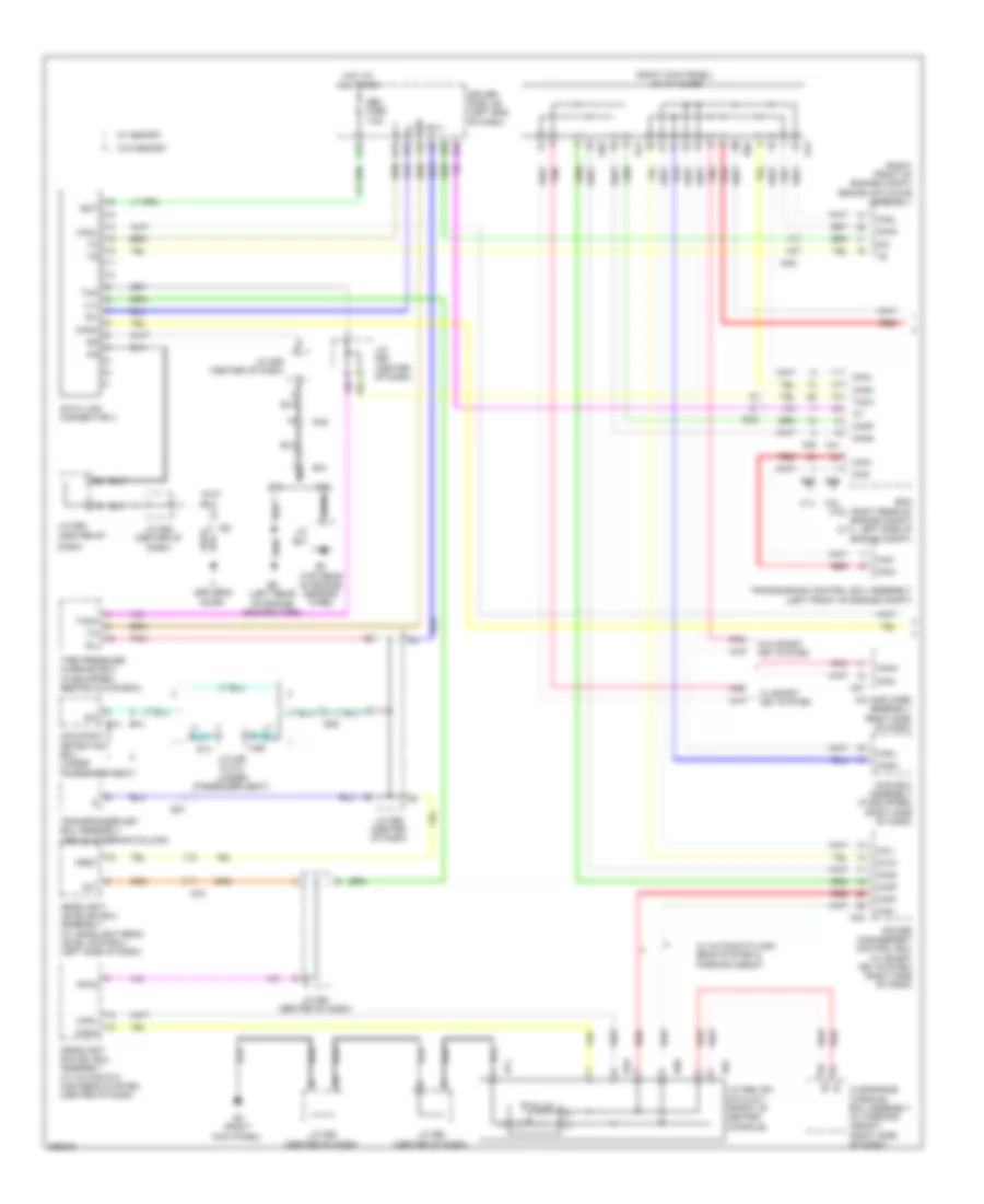
Computer Data Lines Wiring Diagram (1 of 2) for Toyota Venza LE 2013
List of elements for Computer Data Lines Wiring Diagram (1 of 2) for Toyota Venza LE 2013:
- (right front of engine compt) brake actuator assembly
- (right kick panel) j/c a44 & d56
- 2.7l
- 3.5l
- A/c amplifier assembly (right side of dash)
- A41
- A44
- A49
- Awd ecu assembly (if equipped) (right side of dash)
- B3 (top rear of engine (sensor wire))
- B39
- B5 (left rear of engine (engine wire))
- B58
- Ba1
- Bat
- Ca1h
- Ca1l
- Ca2h
- Ca2l
- Ca3n
- Ca3p
- Can+
- Can-
- Canh
- Canl
- Cann
- Canp
- Clearance warning ecu assembly (w/ parking assist) (right side of dash)
- D/g
- D43
- D47
- D5 (right kick panel)
- D56
- D69
- D70
- D71
- D81
- Da1
- Da2
- Da5
- Dash)
- Data link connector 3
- Dd1
- Dia
- Dm2
- Driver side j/b (left end of dash)
- Ecm (3.5l: right rear of engine compt) (2.7l: left side of engine compt)
- F10
- G12
- G34
- Headlight leveling ecu assembly (w/ headlight beam level control) (left side of dash)
- Headlight swivel ecu assembly (w/ automatic high beam system) (center of dash)
- Hot at all times
- I1 (driver's door)
- Id2
- Init
- J/c b41
- J/c d58 (center of dash)
- J/c d59 (center of dash)
- J/c d60 (center of dash)
- J/c d61 (center of dash)
- J/c d62 (center of
- J/c d62 (center of dash)
- J/c d69, d81 d70 & d71 (front of center console)
- J/c m26 & s14 (under passenger seat)
- K12
- K14
- K28
- Lvl
- M14
- M26
- Mpx2
- Obd fuse 7.5a
- Occupant detection ecu (under passenger seat)
- Pnk
- Power management control ecu (w/ smart key system) (right side of dash)
- Prst
- Red
- S12
- S14
- Sil
- St-plug
- Tac
- Tach
- Tire pressure warning ecu (if equipped) (behind glove box)
- Transmission control ecu assembly (left front of engine compt)
- Transponder key ecu assembly (above steering column)
- W/ automatic high beam system & parking assist
- W/ memory
- W/ smart key system
- W/o memory
- W/o smart key system
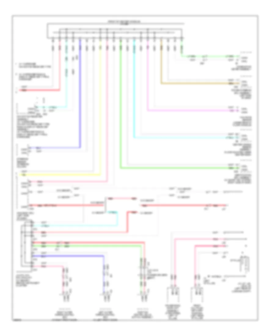
Computer Data Lines Wiring Diagram (2 of 2) for Toyota Venza LE 2013
List of elements for Computer Data Lines Wiring Diagram (2 of 2) for Toyota Venza LE 2013:
- (front of center console) j/c d68
- Canh
- Canl
- Cann
- Canp
- Center air bag sensor assembly (floor mounted under center dash)
- Certification ecu assembly (w/ smart key system) (right side of dash)
- Combination meter assembly
- D20
- D25
- D48
- D73
- D74
- D75
- D76
- D77
- De1
- De2
- Dl1
- E40
- E42
- Front multiplex network door ecu (left rear "d" pillar)
- H13
- Hd1
- I13
- Id1
- J/c d73, d74, d75, d76 & d77 (w/ memory) (behind instrument cluster)
- J/c l24 & t9 (under driver's seat) t9
- J/c l27, l28, l29 & l30 (left rear of luggage compt)
- L2 (left "d" pillar)
- L24
- L27
- L28
- L29
- L30
- Left outer mirror control ecu (in left front door)
- Main body ecu (left side of dash)
- Mpx1
- Mpx2
- Navigation receiver assembly (w/ 13-speaker navigation receiver type) radio & display receiver assembly (w/ 13-speaker radio & display receiver type & 6 speaker)
- Pnk
- Position control ecu & switch assembly
- Power back door unit assembly (if equipped) (left "d" pillar)
- Power steering ecu assembly (left side of dash)
- Red
- Right outer mirror control ecu (in right front door)
- St-plug
- Steering sensor (steering column)
- T11
- W/ 13-speaker navigation receiver type
- W/ 13-speaker radio & display receiver type & 6 speaker
- W/ memory
- W/o memory
- Yaw rate sensor (under rear of floor console)
COOLING FAN
2.7L
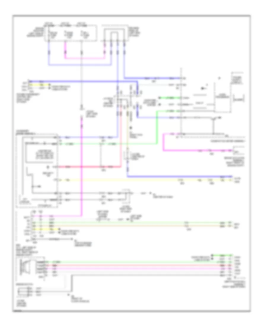
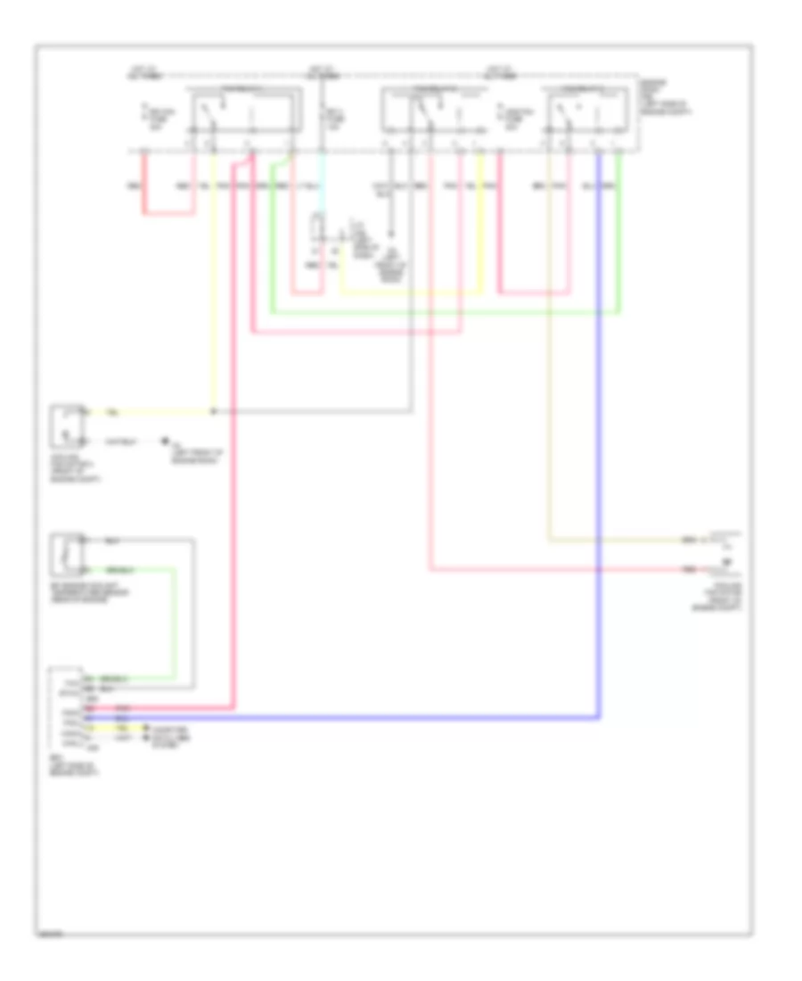
2.7L, Cooling Fan Wiring Diagram for Toyota Venza LE 2013
List of elements for 2.7L, Cooling Fan Wiring Diagram for Toyota Venza LE 2013:
- A4 (left front of engine room)
- A49
- B58
- Canh
- Canl
- Cds fan fuse 30a
- Computer data lines system
- Cooling fan motor (front of engine compt)
- Cooling fan motor 2 (front of engine compt)
- Ecm (left side of engine compt)
- Efi 3 fuse 10a
- Efi engine coolant temperature sensor (rear of engine)
- Engine room r/b (left side of engine compt)
- Ethw
- Fan relay 1
- Fan relay 2
- Fan relay 3
- Fanh
- Fanl
- Hot at all times
- J/c a46 (left side of dash)
- Pnk
- Rdi fan fuse 30a
- Red
- Thw
3.5L
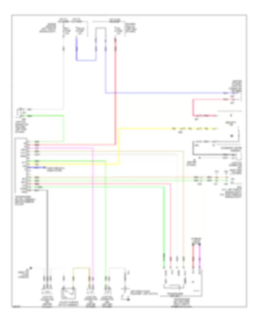
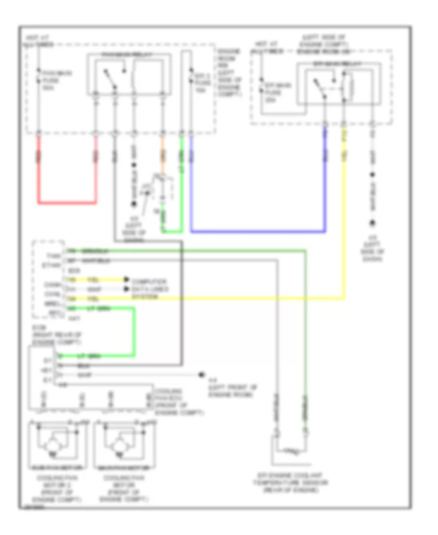
3.5L, Cooling Fan Wiring Diagram for Toyota Venza LE 2013
List of elements for 3.5L, Cooling Fan Wiring Diagram for Toyota Venza LE 2013:
- (left side of engine compt) engine room j/b
- +b1
- A4 (left front of engine room)
- A41
- A5 (left side of dash)
- B39
- Canh
- Canl
- Computer data lines system
- Cooling fan ecu (front of engine compt)
- Cooling fan motor (front of engine compt)
- Cooling fan motor 2 (front of engine compt)
- Ecm (right rear of engine compt)
- Efi 3 fuse 10a
- Efi engine coolant temperature sensor (rear of engine)
- Efi main fuse 25a
- Efi main relay
- Engine room r/b (left side of engine compt)
- Ethw
- F12
- Fan main fuse 50a
- Fan main relay
- Hot at all times
- J/c a46
- M+(m)
- M+(s)
- M-(m)
- M-(s)
- Main fan motor
- Mrel
- Red
- Rfc
- Sub fan motor
- Thw
- Z13
- Z14
CRUISE CONTROL
2.7L
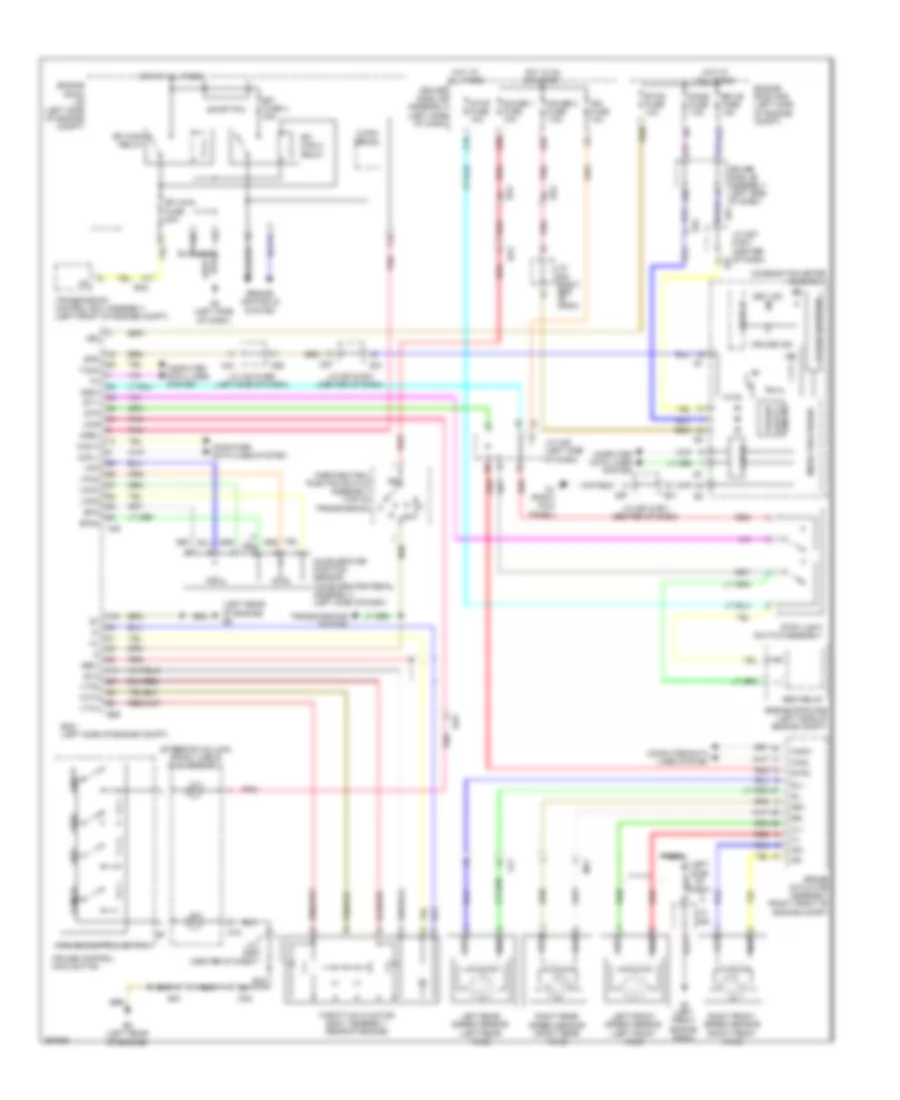
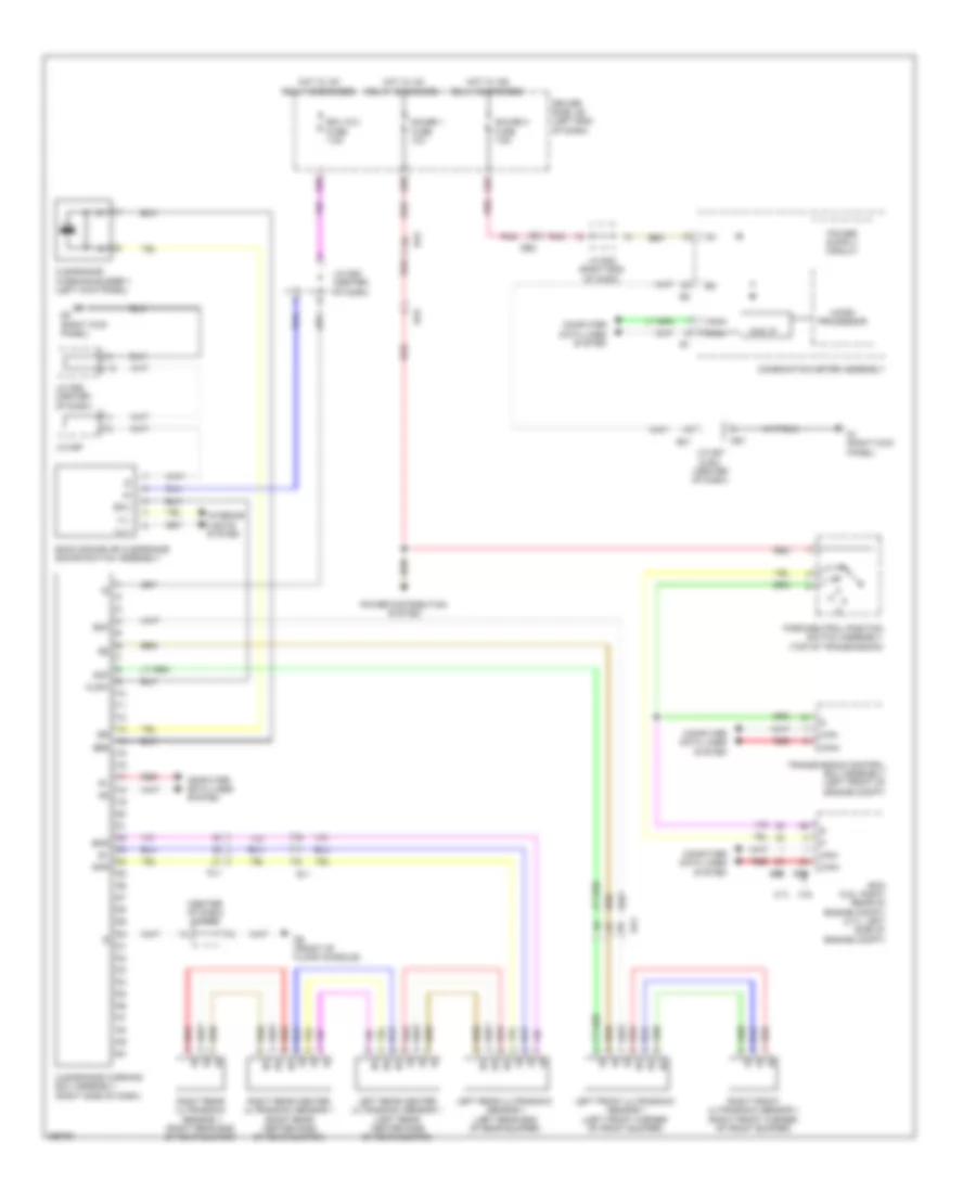
2.7L, Cruise Control Wiring Diagram for Toyota Venza LE 2013
List of elements for 2.7L, Cruise Control Wiring Diagram for Toyota Venza LE 2013:
- (left
- (left front axle)
- (left rear of engine) b5
- (steering column) spiral cable sub-assembly
- +bm
- +res
- -set
- A4 (left front engine room)
- A43
- A49
- A5 (left side of dash)
- Accelerator position sensor (accelerator pedal assembly) (left side of dash)
- B5 (left rear of engine)
- B58
- Ba1
- Ba2
- Brake actuator assembly (right front of engine compt)
- Brk relay
- C/opn relay
- C16
- C24
- C27
- Can h
- Can i/f
- Can l
- Cancel
- Canh
- Canl
- Ccs
- Combination meter assembly
- Computer data lines system
- Cruise control main switch
- Cruise control switch
- Cruise ind
- D1 (right kick panel)
- D18
- D55
- D57
- Da2
- Da5
- De1
- De2
- Dome fuse 7.5a
- Drive ic
- Driver side j/b assembly (left side of dash)
- E31
- Ecm (left side of engine compt)
- Ecu-b fuse 10a
- Efi fuse 4 20a
- Efi main 2 relay
- Efi main fuse 20a
- Efi main relay
- Engine controls system
- Engine room j/b (left side of engine compt)
- Engine room r/b (left side of engine compt)
- Epa
- Epa2
- Eta
- Etcs fuse 10a
- F12
- F20
- Fl+
- Fl-
- Fr+
- Fr-
- G25
- G38
- Gauge 1 fuse 10a
- Gauge 2 fuse 7.5a
- Ge01
- Hot at all times
- Hot in on or start
- Ig2
- Ign fuse 10a
- Igsw
- J/c a43 & d55 (left side of dash)
- J/c a45 (left side of dash)
- J/c a46
- J/c d57 & e31 (center of dash)
- J/c d57 & e31 (center of dash) e31
- J/c d59 (center of dash)
- J/c e32 (right end of dash)
- La1
- Lcd a/t position
- Left front speed sensor
- Left rear speed sensor (left rear axle)
- Ma1
- Micro processor
- Mrel
- Nca
- Of dash)
- On/off
- Park/neutral position switch assembly (top of transmission)
- Pnk
- Power
- Red
- Right front speed sensor (right front axle)
- Right rear speed sensor (right rear axle)
- Rl+
- Rl-
- Rr+
- Rr-
- Set ind
- Short pin
- Side
- Spd
- St1-
- Stop fuse 10a
- Stop light switch assembly
- Stp
- Stp2
- Tach
- Throttle w/ motor body assembly (rear of engine)
- Transmission control ecu assembly (left front of engine compt)
- Transmissions system
- Vcp2
- Vcpa
- Vcta
- Vpa
- Vpa2
- Vta1
- Vta2
3.5L
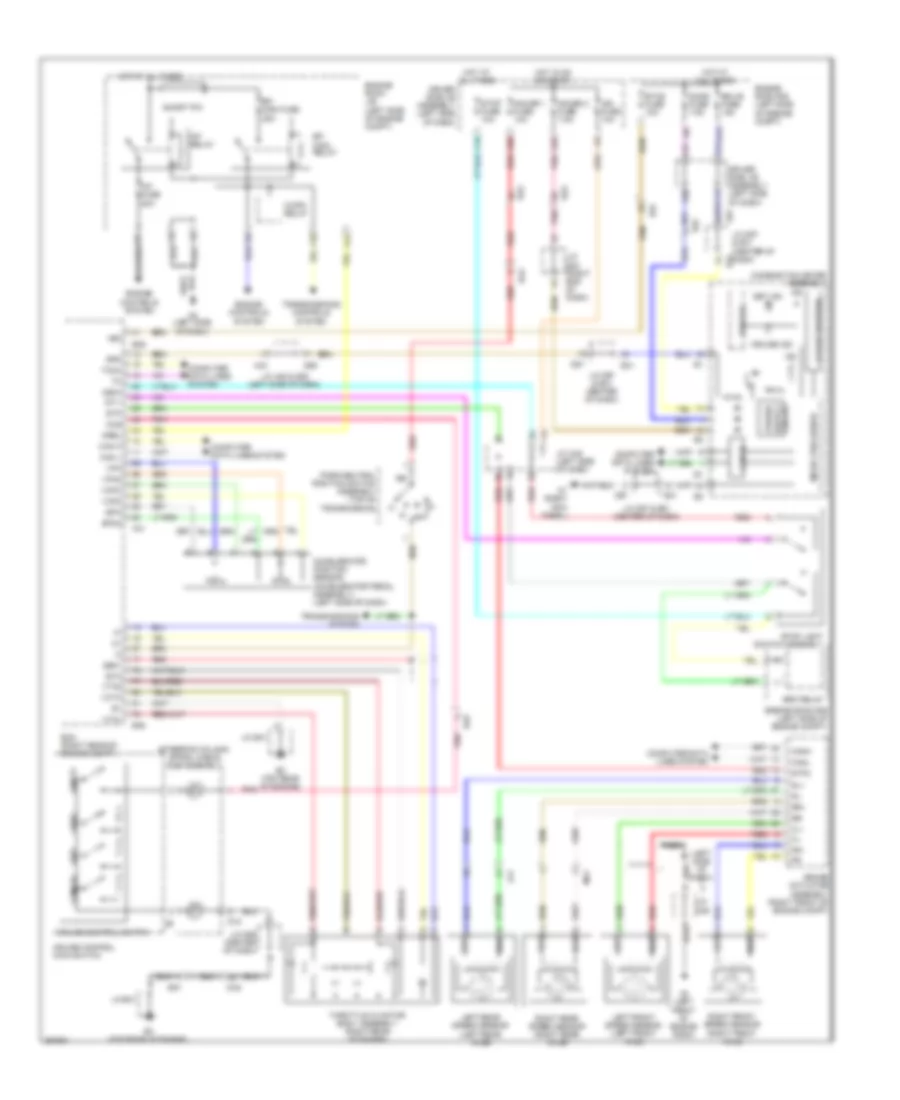
3.5L, Cruise Control Wiring Diagram for Toyota Venza LE 2013
List of elements for 3.5L, Cruise Control Wiring Diagram for Toyota Venza LE 2013:
- (left front axle)
- (left side of dash)
- (steering column) spiral cable sub-assembly
- +bm
- +res
- -set
- A/f fuse 20a
- A/f relay
- A4 (left front of engine room)
- A41
- A43
- A5 (left side of dash)
- Accelerator position sensor (accelerator pedal assembly) (left side of dash)
- B3 (top rear of engine)
- B39
- Ba1
- Ba2
- Brake actuator assembly (right front of engine compt)
- Brk relay
- C/opn relay
- C16
- C24
- C27
- Can h
- Can i/f
- Can l
- Cancel
- Canh
- Canl
- Ccs
- Combination meter assembly
- Computer data lines system
- Cruise control main switch
- Cruise control switch
- Cruise ind
- D1 (right kick panel)
- D18
- D55
- D57
- Da2
- Da5
- De1
- De2
- Dome fuse 7.5a
- Drive ic
- Driver side j/b assembly (left side of dash)
- E31
- Ecm (right rear of engine compt)
- Ecu-b fuse 10a
- Efi main fuse 25a
- Efi main relay
- Engine controls system
- Engine room j/b (left side of engine compt)
- Engine room r/b (left side of engine compt)
- Epa
- Epa2
- Eta
- Etcs fuse 10a
- F12
- F18
- F20
- Fl+
- Fl-
- Fr+
- Fr-
- G25
- G38
- Gauge 1 fuse 10a
- Gauge 2 fuse 7.5a
- Ge01
- Hot at all times
- Hot in on or start
- Ig2
- Ign fuse 10a
- Igsw
- J/c a43 & d55 (left side of dash)
- J/c a45 (left side of dash)
- J/c a46
- J/c b41
- J/c d57 & e31 (center of dash)
- J/c d59 (center of dash)
- J/c e32 (right end of dash)
- La1
- Lcd a/t position
- Left front speed sensor
- Left rear speed sensor (left rear axle)
- Ma1
- Micro processor
- Mrel
- Nca
- On/off
- Park/neutral position switch assembly (top of transmission)
- Pnk
- Power
- Red
- Right front speed sensor (right front axle)
- Right rear speed sensor (right rear axle)
- Rl+
- Rl-
- Rr+
- Rr-
- Set ind
- Short pin
- Spd
- St1-
- Stop fuse 10a
- Stop light switch assembly
- Stp
- Stp2
- Tach
- Throttle w/ motor body assembly (right rear of engine)
- Transmissions controls system
- Transmissions system
- Vcp2
- Vcpa
- Vcta
- Vpa
- Vpa2
- Vta1
- Vta2
DEFOGGERS
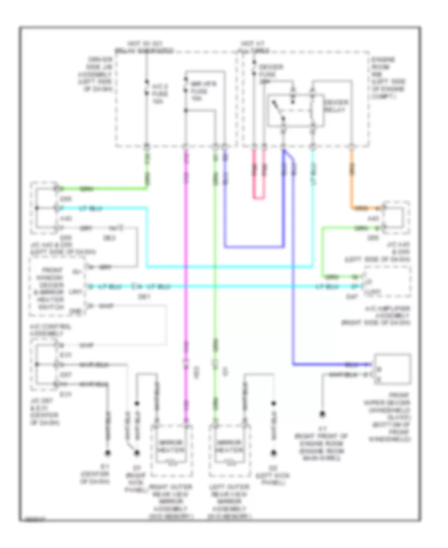
Mirror Heater & Front Deicer Wiring Diagram for Toyota Venza LE 2013
List of elements for Mirror Heater & Front Deicer Wiring Diagram for Toyota Venza LE 2013:
- A/c 2 fuse 10a
- A/c amplifier assembly (right side of dash)
- A/c control assembly
- A1 (right front of engine room (engine room main wire))
- A43
- D1 (right kick panel)
- D2 (left kick panel)
- D47
- D55
- D57
- De1
- De2
- Deicer fuse 20a
- Deicer relay
- Driver side j/b assembly (left side of dash)
- E1 (center of dash)
- E31
- Engine room r/b (left side of engine compt)
- F28
- Front window deicer & mirror heater switch
- Front wiper deicer (windshield glass) (bottom of front windshield)
- Gnd
- Hd2
- Hot at all times
- Hot w/ ig1 relay energized
- Id1
- Ig+
- J/c a43 & d55 (left side of dash)
- J/c d57 & e31 (center of dash)
- J12
- Left outer rear view mirror assembly (w/o memory)
- Lin1
- Mir htr fuse 10a
- Mirror heater
- Pnk
- Right outer rear view mirror assembly (w/o memory)
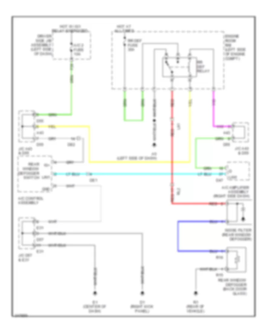
Rear Defogger Wiring Diagram for Toyota Venza LE 2013
List of elements for Rear Defogger Wiring Diagram for Toyota Venza LE 2013:
- A/c 2 fuse 10a
- A/c amplifier assembly (right side dash)
- A/c control assembly
- A43
- A5 (left side of dash)
- D1 (right kick panel)
- D47
- D55
- D57
- De1
- De2
- Driver side j/b assembly (left side of dash)
- E1 (center of dash)
- E31
- Engine room r/b (left side of engine compt)
- F28
- Gnd
- Hot at all times
- Hot w/ ig1 relay energized
- Ig+
- J/c a43 & d55
- J/c d57 & e31
- La1
- Lin1
- Noise filter (rear window defogger)
- R1 (rear of vehicle)
- R15
- R16
- Rear window defogger (back door glass)
- Rear window defogger switch
- Red
- Rl2
- Rr def fuse 30a
- Rr def relay
ELECTRONIC POWER STEERING
Electronic Power Steering Wiring Diagram for Toyota Venza LE 2013
List of elements for Electronic Power Steering Wiring Diagram for Toyota Venza LE 2013:
- (left side of dash)
- (right kick panel) d1
- Accessory meter assembly
- Ad1
- Bat
- C24
- C27
- Can i/f
- Canh
- Canl
- Combination meter assembly
- Computer data lines system
- D19
- D20
- D4 (left kick panel)
- D57
- De1
- De2
- Dome fuse 7.5a
- Driver side j/b (left end of dash)
- E31
- Ecu-b 2 fuse 7.5a
- Ecu-b fuse 10a
- Ecu-ig 2 fuse 7.5a
- Ef2
- Engine room j/b (left side of engine compt)
- Engine room r/b (left side of engine compt)
- Eps fuse 80a
- Ess
- F20
- G25
- Gauge 2 fuse 7.5a
- Hot at all times
- Hot in on or start
- I1 (driver's door)
- Id2
- Ig+
- Ind
- J/c d58 (center of dash)
- J/c d62 (center of dash)
- J/c d63 (center of dash)
- J/c d64 (left end of dash)
- J/c e32 (right end of dash)
- Junction connector d57 & e31 (center of dash)
- K16
- K35
- K36
- Micro processor
- Motor resolver
- Pgnd
- Pig
- Pnk
- Power steering ecu assembly
- Power steering ind
- Power steering motor assembly
- Power steering torque sensor
- Red
- Rzcs
- Rzg
- Rzsn
- Rzv
- Steering sensor (steering column)
- Trq1
- Trq2
- Trqg
- Trqv
- Z10
ENGINE PERFORMANCE
2.7L
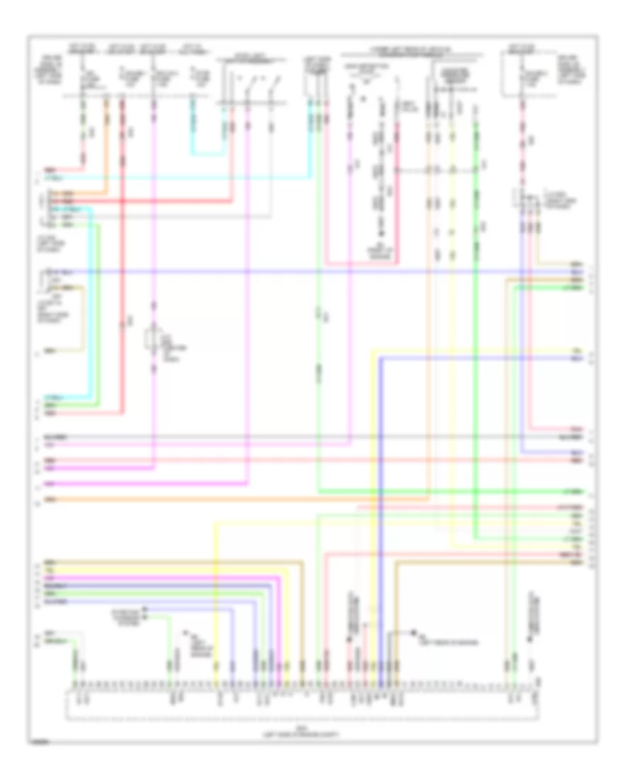
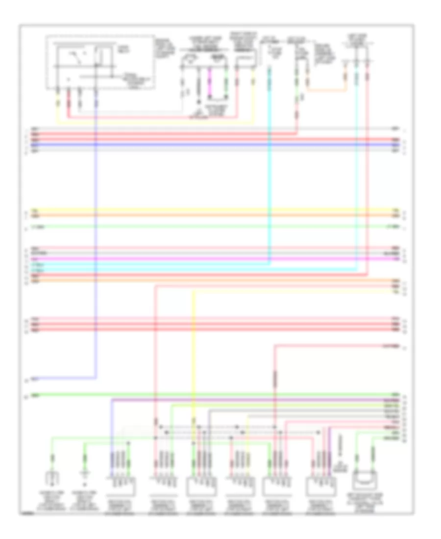
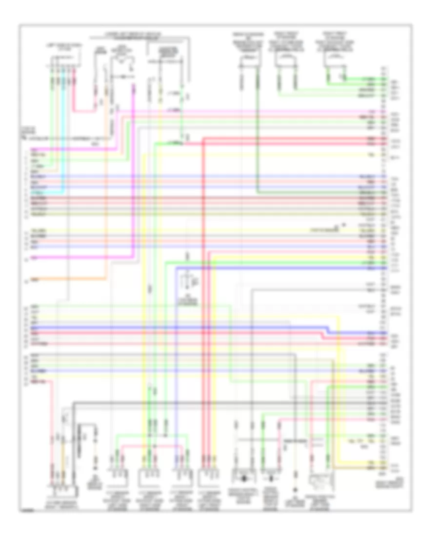
2.7L, Engine Performance Wiring Diagram (1 of 4) for Toyota Venza LE 2013
List of elements for 2.7L, Engine Performance Wiring Diagram (1 of 4) for Toyota Venza LE 2013:
- (left "c" pillar) l3
- (left side of dash) j/c a46
- (under left side of rear seat) fuel sender gauge assembly
- +b2
- +bm
- A43
- A49
- A5 (left side of dash)
- Accelerator position sensor (accelerator pedal assembly) (left side of dash)
- Ae1
- Anti-theft system
- Ba2
- Batt
- C/opn relay
- Camshaft timing oil control valve (bank 1 exhaust side) (top right of engine)
- Camshaft timing oil control valve (bank 1 intake side) (right side of engine)
- Canh
- Canl
- Cann
- Canp
- Ccs
- Computer data lines system
- Cooling fans system
- Cruise control system
- D42
- D55
- Da5
- Ecm (left side of engine compt)
- Ef2
- Efi 1 fuse 10a
- Efi 2 fuse 15a
- Efi 3 fuse 10a
- Efi 4 fuse 20a
- Efi main 2 relay
- Efi main fuse 20a
- Efi main relay
- Engine room j/b (left side of engine compt)
- Engine room r/b (left side of engine compt)
- Epa
- Epa2
- Etcs fuse 10a
- F10
- F12
- Fanh
- Fanl
- Gauge
- Hot at all times
- I1 (driver's door)
- Id2
- Igsw
- Imi
- Imo
- Instrument cluster system
- J/c a43 & d55 (left side of dash)
- J/c a43 (left side of dash)
- J/c d58 (center of dash)
- J/c d62 (center of dash)
- La1
- Mpmp
- Mrel
- Neo
- Park/neutral position switch assembly (top of transmission)
- Pnk
- Power management control ecu (w/ smart key system) (right side of dash)
- Pump
- Red
- Sftd
- Sftu
- Short pin
- Spd
- St1-
- Sta
- Starting/charging system
- Stp
- Tach
- Transmission control ecu assembly (left front of engine compt)
- Transmission control switch
- Transmissions system
- Vcp2
- Vcpa
- Vpa
- Vpa2
- Vpmp
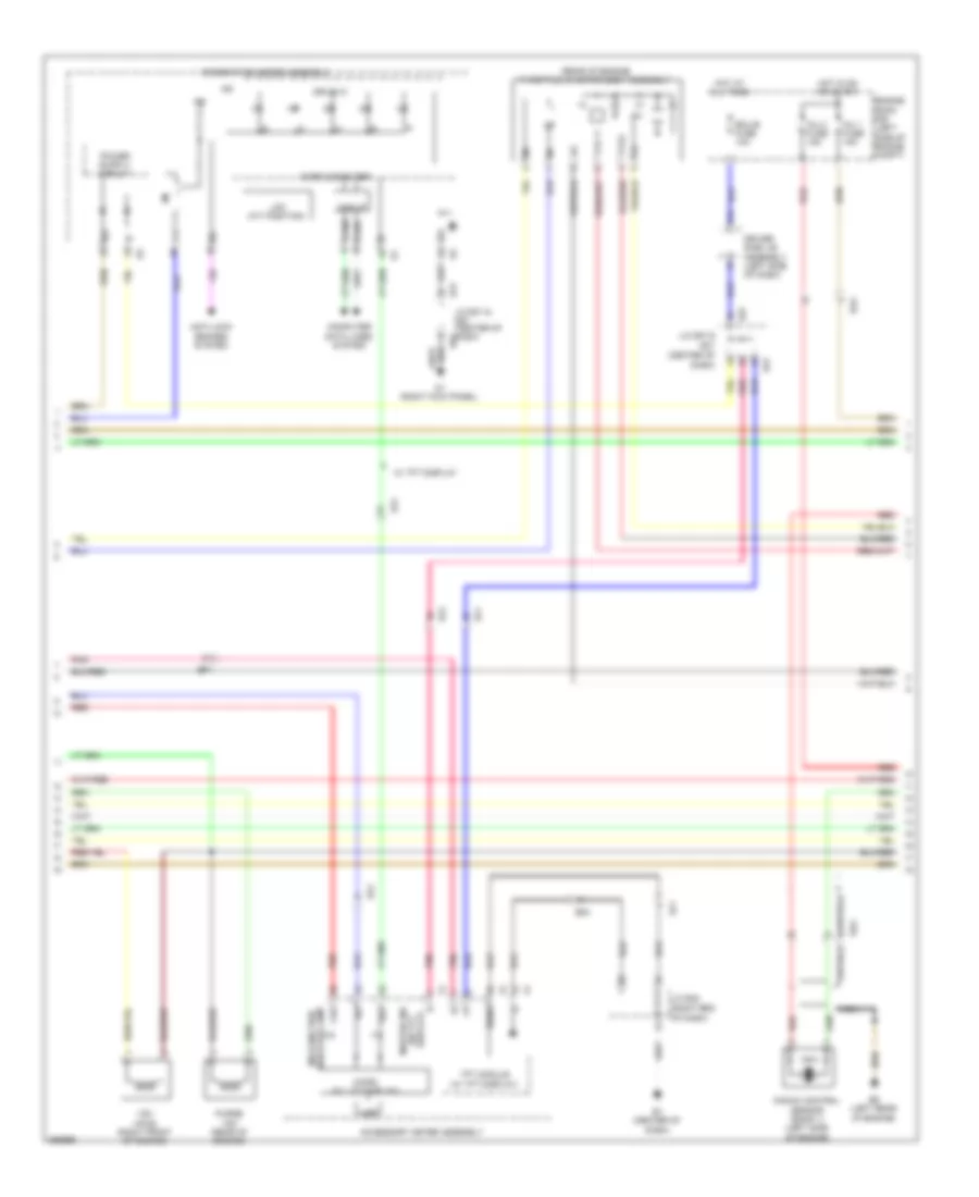
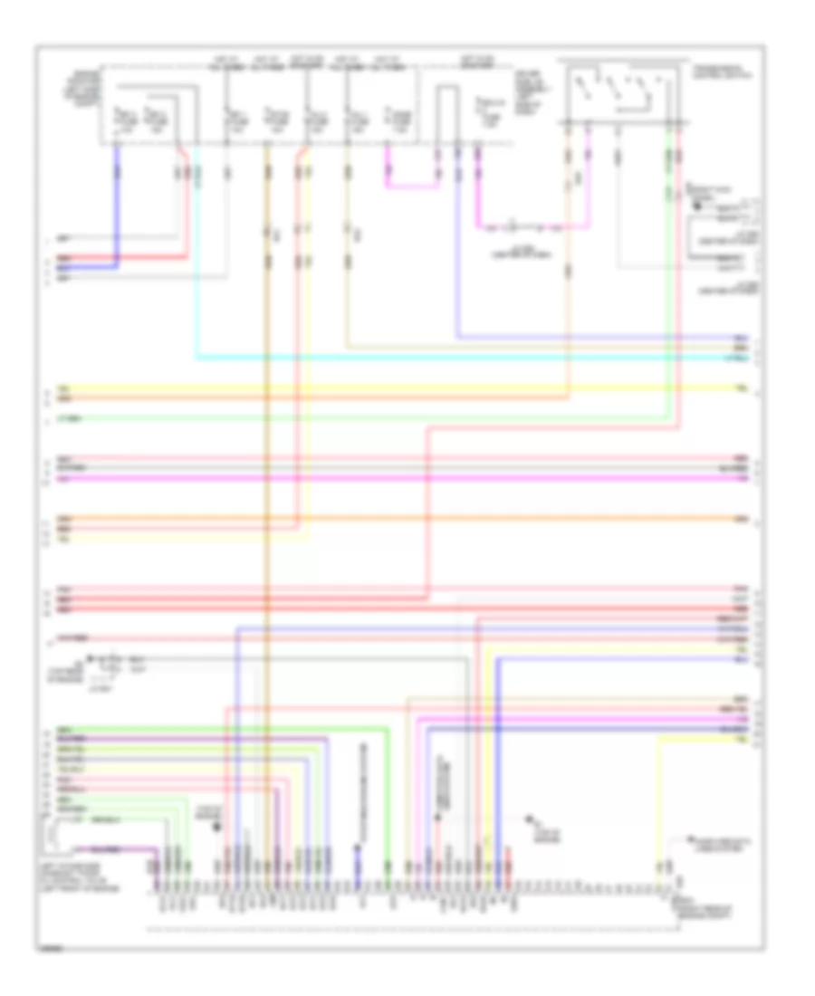
2.7L, Engine Performance Wiring Diagram (2 of 4) for Toyota Venza LE 2013
List of elements for 2.7L, Engine Performance Wiring Diagram (2 of 4) for Toyota Venza LE 2013:
- (left side of dash) j/c a46
- (under left rear of vehicle) canister pump module
- Acis
- Alt
- B4 (front of engine)
- B58
- B6 (left rear of engine)
- Ba1
- Ba2
- C16
- Can+
- Can-
- Canister pressure sensor
- Computer data lines system
- D57
- Da2
- De2
- Driver side j/b assembly (left side of dash)
- E04
- E31
- Ecm (left side of engine compt)
- Ecu-ig 2 fuse 7.5a
- G25
- G38
- Gauge 1 fuse 10a
- Gauge 2 fuse 7.5a
- Ge01
- Ha1a
- Hot at all times
- Hot in on or start
- Ht1b
- Ia1+
- Ia1-
- Igf1
- Ign fuse 10a
- J/c a45 (left side of dash)
- J/c d63 (center of dash)
- J/c e31 & d57 (right side of dash)
- J/c e32 (right end of dash)
- K29
- K36
- La1
- Leak detection pump
- Lines system computer data
- Me01
- Mgnd
- Mtrb
- Nsw
- Oc1+
- Oc1-
- Oe1+
- Oe1-
- Pnk
- Prg
- Red
- Sgnd
- Starting/ charging system
- Stop fuse 10a
- Stop light switch assembly
- Vcc
- Vent valve
- Vgnd
- Vlvb
- Vout
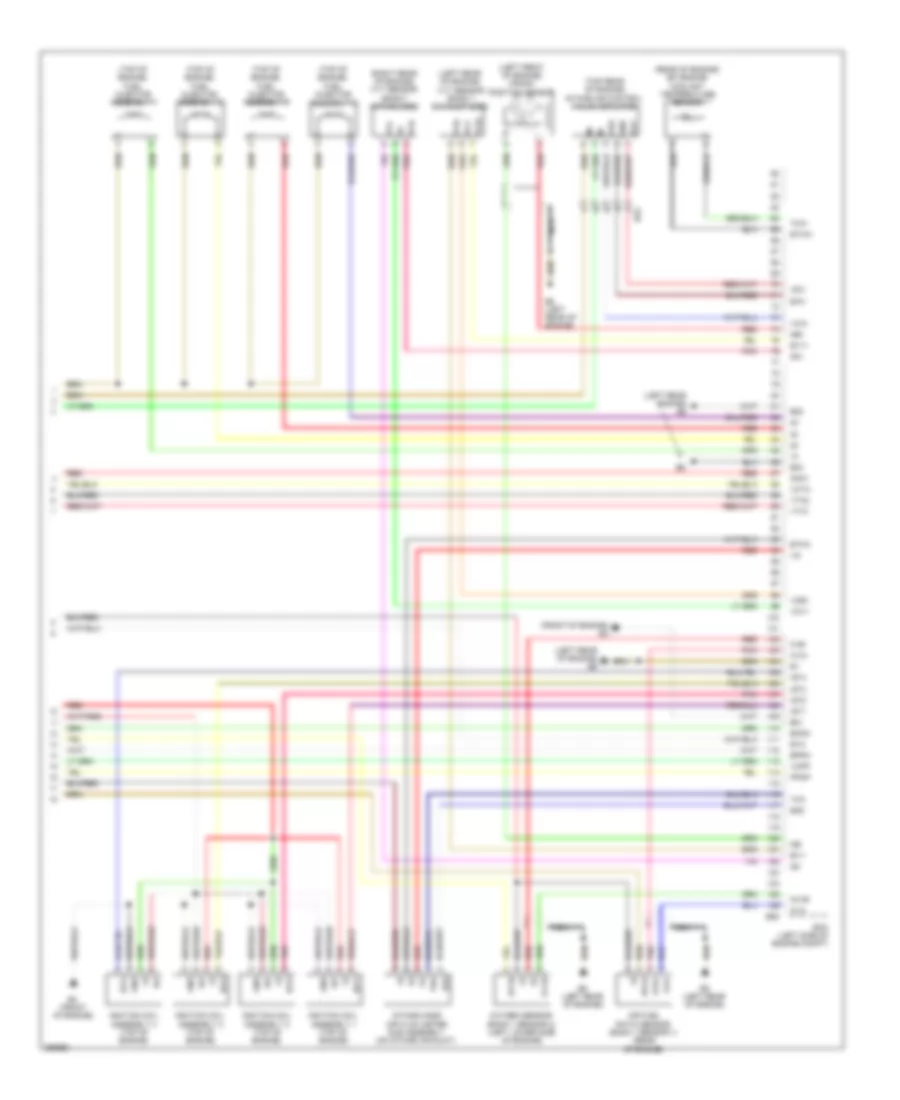
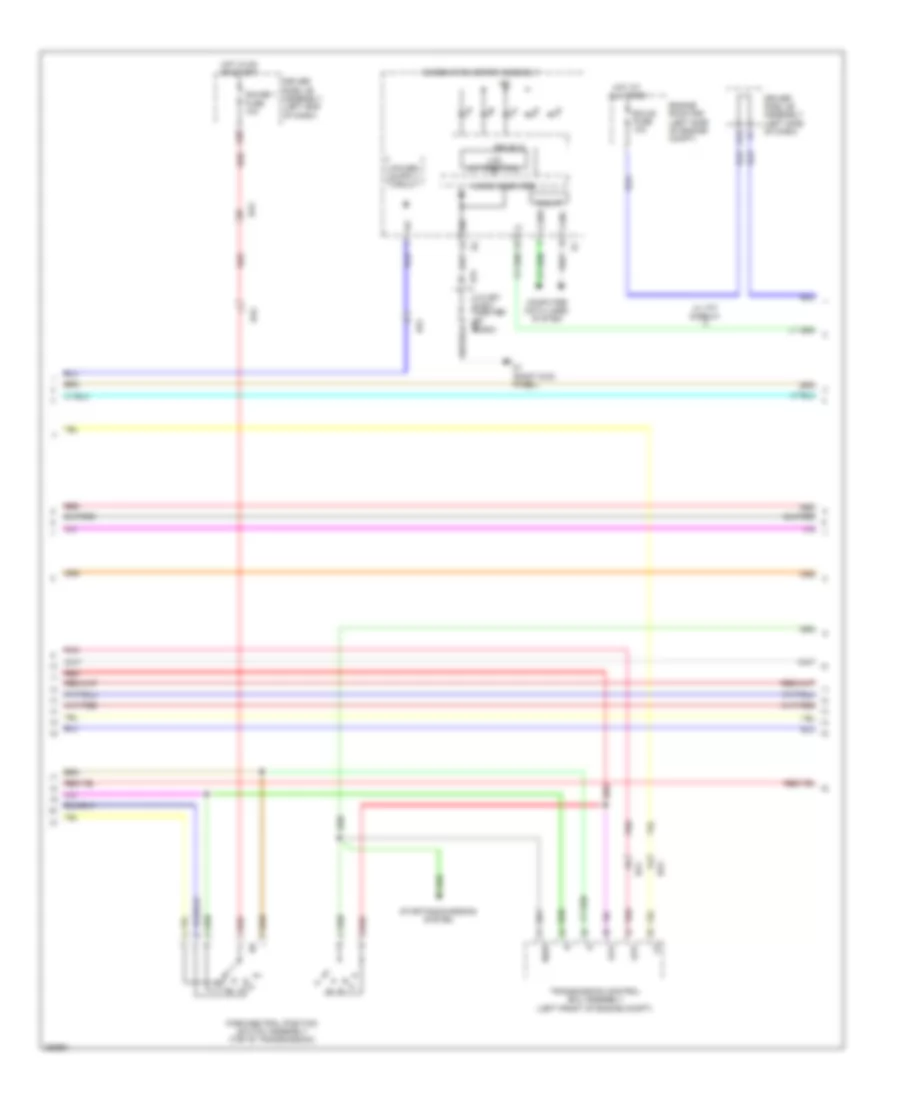
2.7L, Engine Performance Wiring Diagram (3 of 4) for Toyota Venza LE 2013
List of elements for 2.7L, Engine Performance Wiring Diagram (3 of 4) for Toyota Venza LE 2013:
- (center of dash)
- (rear of engine) throttle w/ motor body assembly
- (right end of dash)
- Accessory meter assembly
- Anti-lock brakes system
- B5 (left rear of engine)
- Ba2
- Bu2
- C24
- Can i/f
- Canh
- Canl
- Chk
- Combination meter assembly
- Computer data lines system
- D1 (right kick panel)
- D57
- Display) (w/ tft master ind
- Drive ic
- Driver side j/b assembly (left side of dash)
- E1 (center of dash)
- E31
- Ecu-b fuse 10a
- Ef1
- Ef2
- Engine room r/b (left side of engine compt)
- Hot at all times
- Hot in on or start
- Ig+
- Ig2
- Indicator lamp malfunction
- Inj 1 fuse 15a
- Inj 2 fuse 15a
- J/c d57 & e31
- J/c e31 & d57 (center of dash) d57
- J/c e32
- Knock control sensor (bank 1) (left side of engine)
- Lcd
- Lcd (a/t position)
- Micro (w/ lcd display)
- Micro computer
- Nca
- Pnk
- Purge vsv (rear of engine)
- Red
- Sg7
- Sgnd
- Tft module (w/ tft display)
- Vsv (acis) (right front of engine)
- Vta
- Vta2
- W/ tft display
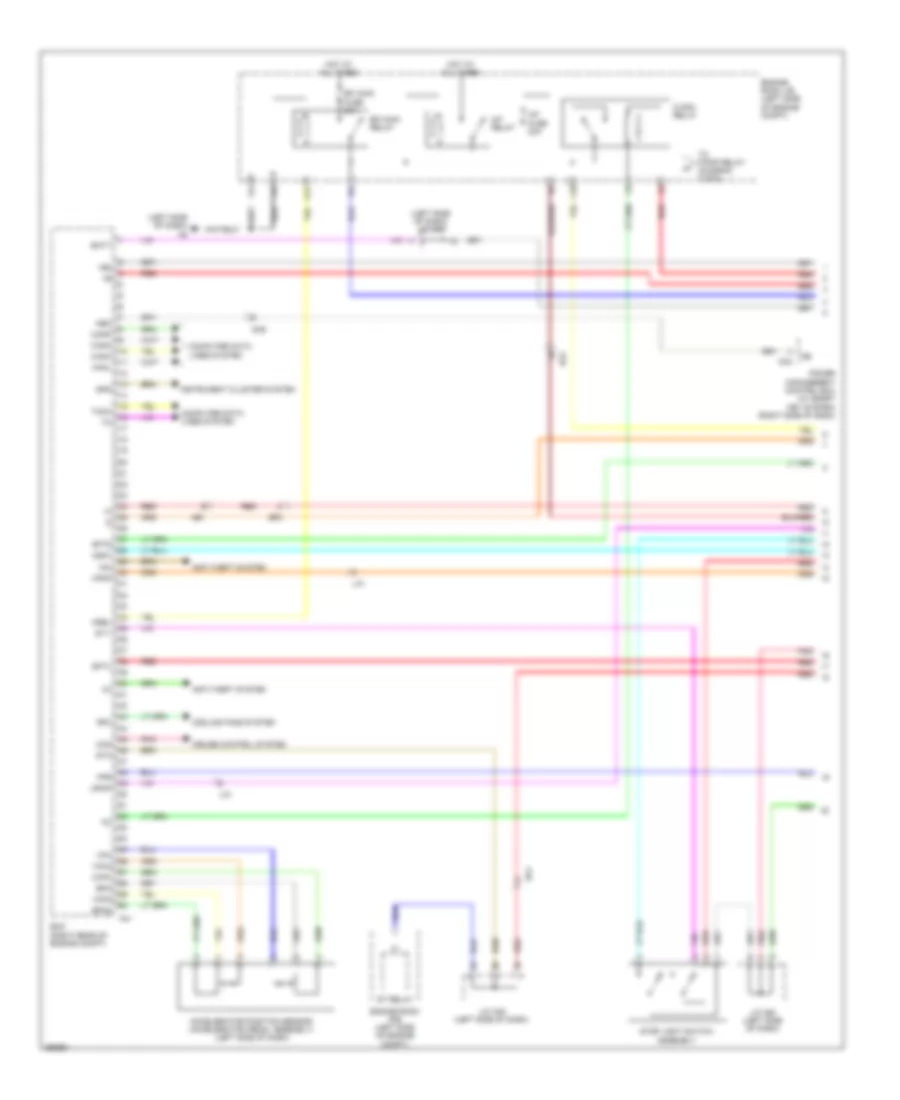
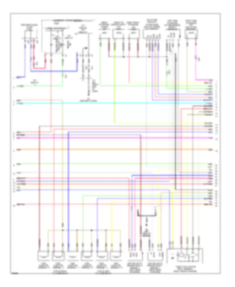
2.7L, Engine Performance Wiring Diagram (4 of 4) for Toyota Venza LE 2013
List of elements for 2.7L, Engine Performance Wiring Diagram (4 of 4) for Toyota Venza LE 2013:
- (front of engine)
- (front of engine) b4
- (left front of engine) crank position sensor
- (left rear engine) b6
- (left rear of engine)
- (left rear of engine) b5
- (left rear of engine) vvt sensor (bank 1 exhaust side)
- (rear of engine) efi engine coolant temperature sensor
- (right rear of engine) vvt sensor (bank 1 intake side)
- (top of engine) fuel injector assembly 1
- (top of engine) fuel injector assembly 2
- (top of engine) fuel injector assembly 3
- (top of engine) fuel injector assembly 4
- (top rear of engine) intake air control valve actuator
- A1a+
- A1a-
- Air fuel ratio sensor (bank 1 sensor 1) (rear of engine)
- B5 (left rear of engine)
- B58
- Bu2
- E01
- E02
- E03
- E2g
- Ecm (left side of engine compt)
- Eia1
- Eknk
- Eppm
- Eta
- Etha
- Ethw
- Ev1+
- Ev1-
- G2+
- G2-
- Gnd
- Ha1a
- Ht1b
- Iac1
- Igf
- Ignition coil assembly 1 (top of engine)
- Ignition coil assembly 2 (top of engine)
- Ignition coil assembly 3 (top of engine)
- Ignition coil assembly 4 (top of engine)
- Igt1
- Igt2
- Igt3
- Igt4
- Intake mass air flow meter sub assembly (on intake air duct)
- Knk1
- Nca
- Ne+
- Ne-
- O1b-
- Out
- Ox1b
- Oxygen sensor (bank 1 sensor 2) (left lower side of engine)
- Pnk
- Ppmp
- Red
- Tha
- Thw
- Vc2
- Vce1
- Vcia
- Vcpp
- Vcta
- Vcv1
- Vdd
- Vta1
- Vta2
- Vve+
- Vve-
- Vvi+
- Vvi-
3.5L
3.5L, Engine Performance Wiring Diagram (1 of 6) for Toyota Venza LE 2013
List of elements for 3.5L, Engine Performance Wiring Diagram (1 of 6) for Toyota Venza LE 2013:
- (left side of dash) a5
- (left side of dash) j/c a43
- +b2
- A/f fuse 20a
- A/f relay
- A41
- Accelerator position sensor (accelerator pedal assembly) (left side of dash)
- Ae1
- Anti-theft system
- Ba1
- Ba2
- Batt
- C/opn relay
- Canh
- Canl
- Cann
- Canp
- Ccs
- Computer data lines system
- Cooling fans system
- Cruise control system
- D42
- Da5
- Ecm (right rear of engine compt)
- Ef2
- Efi main fuse 25a
- Efi main relay
- Engine room j/b (left side of engine compt)
- Engine room r/b (left side of engine compt)
- Epa
- Epa2
- F12
- F18
- Fpr
- Hot at all times
- Igsw
- Imi
- Imo
- Instrument cluster system
- J/c a45 (left side of dash)
- La1
- Mpmp
- Mrel
- Neo
- Pnk
- Power management control ecu (w/ smart key system) (right side of dash)
- Red
- Rfc
- Sftd
- Sftu
- Spd
- St relay
- St1-
- Sta
- Stop light switch assembly
- Tach
- To f/pmp relay (diagram 2 of 6)
- Vcp2
- Vcpa
- Vpa
- Vpa2
- Vpmp
3.5L, Engine Performance Wiring Diagram (2 of 6) for Toyota Venza LE 2013
List of elements for 3.5L, Engine Performance Wiring Diagram (2 of 6) for Toyota Venza LE 2013:
- (left side of dash) j/c a45
- (right side of engine compt) fuel pump resistor assembly
- (under left side of rear seat) fuel sender gauge assembly
- B1 (top of engine)
- C16
- Da2
- Driver side j/b assembly (left side of dash)
- Engine room j/b (left side of engine compt)
- F/pmp relay
- F10
- F11
- F13
- From c/opn relay (diagram 1 of 6)
- Gauge
- Gnd
- Hot at all times
- Hot in on or start
- Igf
- Ign fuse 10a
- Ignition coil assembly 1 (top of right cylinder bank)
- Ignition coil assembly 2 (top of left cylinder bank)
- Ignition coil assembly 3 (top of right cylinder bank)
- Ignition coil assembly 4 (top of left cylinder bank)
- Ignition coil assembly 5 (top of right cylinder bank)
- Ignition coil assembly 6 (top of left cylinder bank)
- Igt1
- Igt2
- Igt3
- Igt4
- Igt5
- Igt6
- Instrument cluster system
- K29
- L3 (left "c" pillar)
- La1
- Left exhaust side camshaft timing oil control valve (left side of engine)
- Noise filter (ignition bank 1) (top of right cylinder bank)
- Noise filter (ignition bank 2) (top of left cylinder bank)
- Pnk
- Pump
- Red
- Stop fuse 10a
3.5L, Engine Performance Wiring Diagram (3 of 6) for Toyota Venza LE 2013
List of elements for 3.5L, Engine Performance Wiring Diagram (3 of 6) for Toyota Venza LE 2013:
- (right kick panel) da5
- (top of engine)
- +bm
- Alt
- B1 (top of engine)
- B3 (top rear of engine)
- B39
- Ba1
- Ba2
- C27
- Can+
- Can-
- Computer data lines system
- Da5
- Dome fuse 7.5a
- Driver side j/b assembly (left side of dash)
- Ecm (right rear of engine compt)
- Ecu-ig fuse 7.5a
- Efi 1 fuse 10a
- Efi 2 fuse 15a
- Efi 3 fuse 10a
- Engine room r/b (left side of engine compt)
- Eo1
- Eo2
- Eo3
- Eo4
- Eo5
- Etcs fuse 10a
- F20
- Ge01
- Ha1a
- Ha2a
- Hot at all times
- Hot in on or start
- Ht1b
- Ht2b
- Igt1
- Igt2
- Igt3
- Igt4
- Igt5
- Igt6
- Inj 1 fuse 15a
- Inj 2 fuse 15a
- J/c b41
- J/c d58 (center of dash)
- J/c d62 (center of dash)
- J/c d63 (center of dash)
- K36
- Left intake side camshaft timing oil control valve (left front of engine)
- Lines system computer data
- Oc2+
- Oc2-
- Oe2+
- Oe2-
- Pnk
- Red
- Starting/charging system
- Stp
- Transmission control switch
3.5L, Engine Performance Wiring Diagram (4 of 6) for Toyota Venza LE 2013
List of elements for 3.5L, Engine Performance Wiring Diagram (4 of 6) for Toyota Venza LE 2013:
- Ba1
- Ba2
- C24
- Can i/f
- Canh
- Canl
- Combination meter assembly
- Computer data lines system
- D1 (right kick panel)
- Da2
- De1
- Drive ic
- Driver side j/b assembly (left end of dash)
- Driver side j/b assembly (left side of dash)
- E31
- Ecu-b fuse 10a
- Engine room r/b (left side of engine compt)
- G38
- Gauge 1 fuse 10a
- Hot at all times
- Hot in on or start
- Ig2
- J/c d57 & e31 (center of d57 dash)
- Lcd (a/t position)
- Micro computer
- Nsw
- Park/neutral position switch assembly (top of transmission)
- Pnk
- Red
- Sta
- Starting/charging system
- Stp
- Transmission control ecu assembly (left front of engine compt)
- W/ tft display
3.5L, Engine Performance Wiring Diagram (5 of 6) for Toyota Venza LE 2013
List of elements for 3.5L, Engine Performance Wiring Diagram (5 of 6) for Toyota Venza LE 2013:
- (center of dash) j/c d57 & e31
- (front of engine compt) vsv (acm)
- (left side of engine) oxygen sensor (bank 2 sensor 2)
- (on intake air duct)
- (rear of engine) purge vsv
- (right front of engine)
- (right rear of engine)
- (right side of engine) vsv (air intake control)
- (top of left cylinder bank)
- (top of right cylinder bank)
- A1a+
- A1a-
- A2a+
- A2a-
- Accessory meter assembly
- Air fuel ratio sensor (bank 1 sensor 1) (right rear of engine)
- Air fuel ratio sensor (bank 2 sensor 1) (left rear of engine)
- B2 (left rear of engine)
- Ba1
- Ba2
- D57
- E1 (center of dash)
- E2g
- E31
- Ef1
- Ef2
- Fuel injector assembly 1
- Fuel injector assembly 2
- Fuel injector assembly 3
- Fuel injector assembly 4
- Fuel injector assembly 5
- Fuel injector assembly 6
- Ha1a
- Ha2a
- Ht2b
- Intake mass air flow meter sub assembly
- J/c e32 (right end of dash)
- Lcd
- Lcd display
- Malfunction indicator lamp
- Master ind
- Micro (lcd display)
- Nca
- Ox2b
- Pnk
- Red
- Tft display
- Tft module (tft display)
- Tha
- Throttle w/ motor body assembly
- Vsv (acis)
3.5L, Engine Performance Wiring Diagram (6 of 6) for Toyota Venza LE 2013
List of elements for 3.5L, Engine Performance Wiring Diagram (6 of 6) for Toyota Venza LE 2013:
- (front of engine)
- (left side of dash) j/c a46
- (rear of engine) efi engine coolant temperature sensor
- (right front of engine)
- (top of engine) b1
- (under left rear of vehicle)
- A1a+
- A1a-
- A2a+
- A2a-
- Acis
- Acm
- Aicv
- B1 (top of engine)
- B2 (left rear of engine)
- B3 (top rear of engine)
- B39
- Ba1
- Ba2
- Bu1
- Canister pressure sensor
- Canister pump module
- Crank position sensor (left side of engine)
- E2g
- Ecm (right rear of engine compt)
- Ekn2
- Eknk
- Eta
- Etha
- Ethw
- Ev1+
- Ev2+
- Ex+
- Ex-
- Ex1b
- Ex2b
- Ht1b
- Igf1
- J/c b41
- Knk1
- Knk2
- Knock control sensor (bank 1) (top of engine)
- Knock control sensor (bank 2) (top of engine)
- La1
- Leak detection pump
- Meo1
- Nca
- Ne+
- Ne-
- Nsw
- Oc1+
- Oc1-
- Oe1+
- Oe1-
- Ox1b
- Ox2b
- Oxygen sensor (bank 1 sensor 2)
- Pnk
- Ppmp
- Prg
- Red
- Right exhaust side camshaft timing oil control valve
- Right intake side camshaft timing oil control valve
- Tha
- Thw
- Vc2
- Vcta
- Vcv1
- Vcv2
- Vent valve
- Vta1
- Vta2
- Vv1+
- Vv1-
- Vv2+
- Vv2-
- Vvl+
- Vvl-
- Vvr+
- Vvr-
- Vvt sensor (bank 1 exhaust side) (right side of engine)
- Vvt sensor (bank 1 intake side)
- Vvt sensor (bank 2 exhaust side) (left side of engine)
- Vvt sensor (bank 2 intake side) (left front of engine)
EXTERIOR LIGHTS
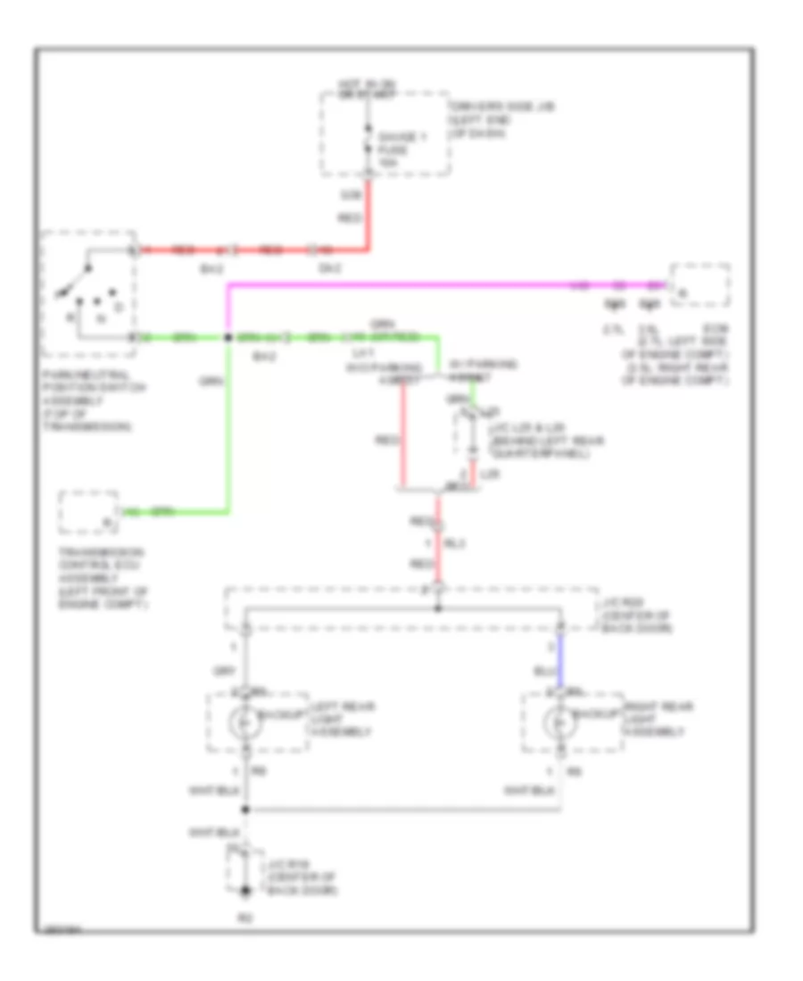
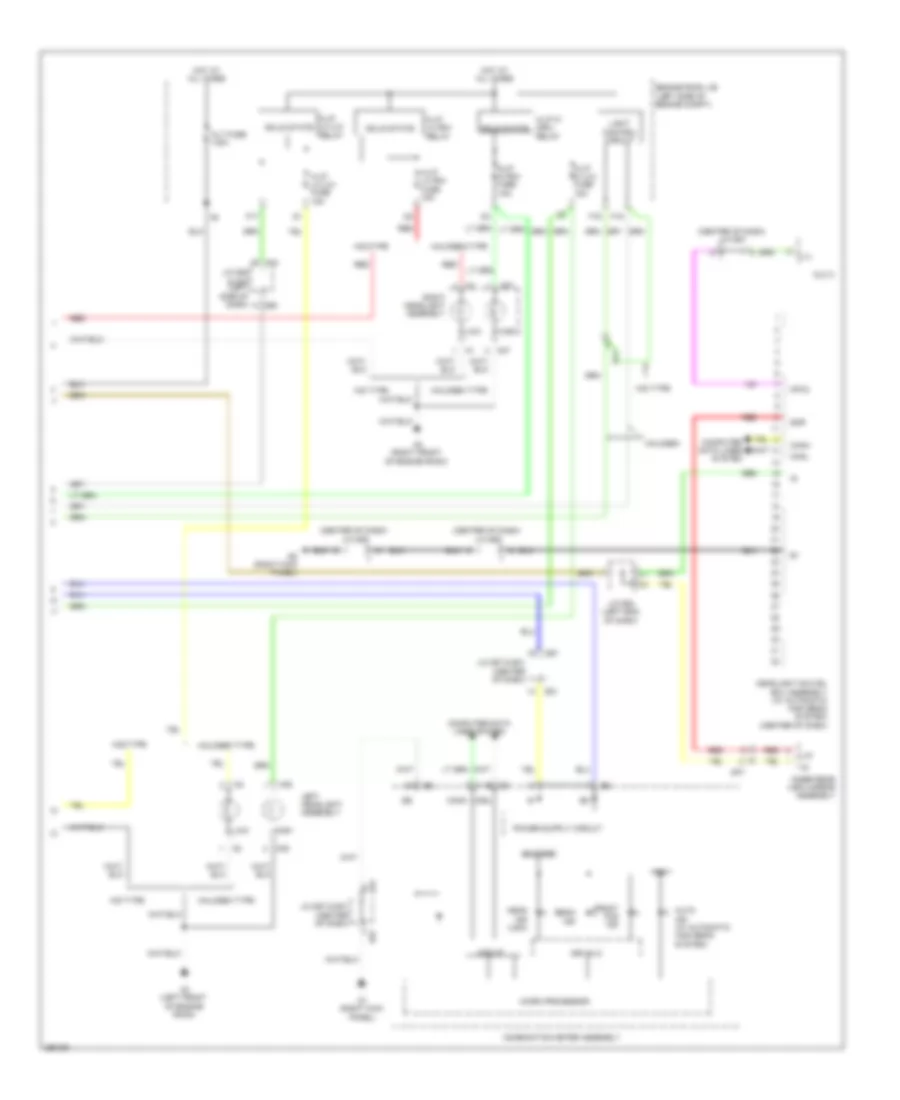
Backup Lamps Wiring Diagram for Toyota Venza LE 2013
List of elements for Backup Lamps Wiring Diagram for Toyota Venza LE 2013:
- 2.7l
- 3.5l
- B39
- B58
- Ba2
- Backup
- Da2
- Driver's side j/b (left end of dash)
- Ecm (2.7l: left side of engine compt) (3.5l: right rear of engine compt)
- G38
- Gauge 1 fuse 10a
- Hot in on or start
- J/c l25 & l26 (behind left rear quarterpanel)
- J/c r19 (center of back door)
- J/c r20 (center of back door)
- L25
- L26
- La1
- Left rear light assembly
- Park/neutral position switch assembly (top of transmission)
- Red
- Right rear light assembly
- Rl3
- Transmission control ecu assembly (left front of engine compt)
- W/ parking assist
- W/o parking assist
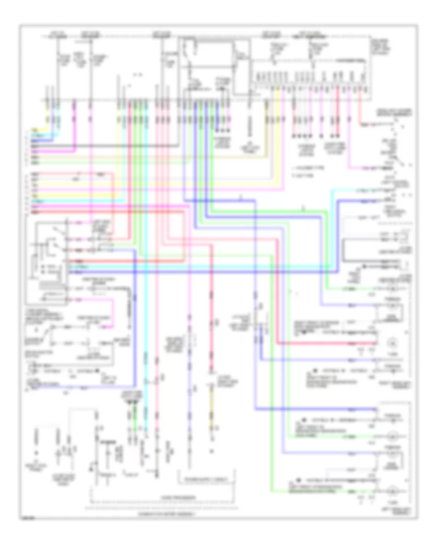
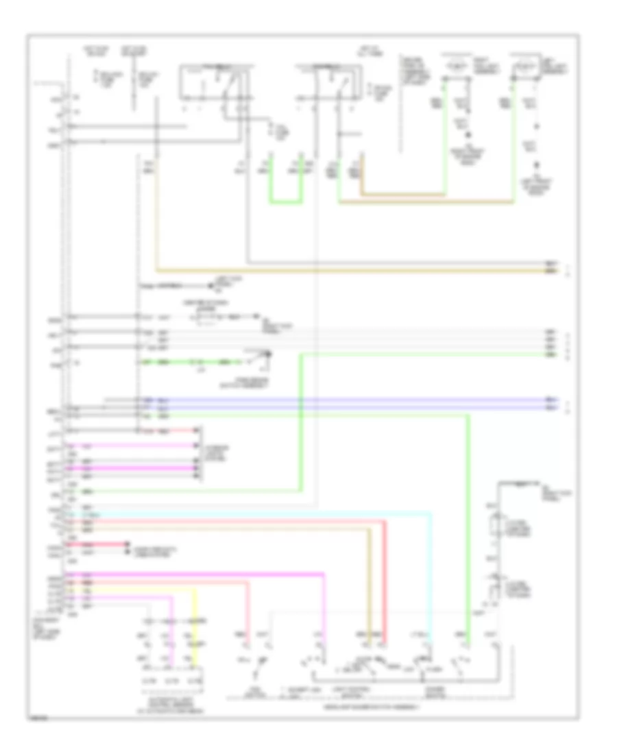
Exterior Lamps Wiring Diagram (1 of 2) for Toyota Venza LE 2013
List of elements for Exterior Lamps Wiring Diagram (1 of 2) for Toyota Venza LE 2013:
- (2.7l)
- (3.5l)
- (center of dash) j/c d63
- (in right front door) right outer mirror control ecu
- (left side of dash) j/c a45
- (right kick panel) d1
- A41
- A49 stp
- Alt fuse 140a
- Automatic light control sensor
- Ba1
- Backup
- Backup lamps circuit
- Brake actuator assembly (right front of engine compt)
- Brk relay
- Center stop light assembly
- Cltb
- Clte
- Clts
- Cruise control system
- D2 (left kick panel)
- D42
- Da1
- De2
- Dl2
- Dome fuse 7.5a
- Door 1 fuse 20a
- Ecm (3.5l: right rear of engine compt) (2.7l: left side of engine compt)
- Ef1
- Engine room j/b (left side of engine compt)
- Engine room r/b (left side of engine compt)
- Gnd
- H12
- H13
- Haz fuse 15a
- Hot at all times
- J/c a45 (left side of dash)
- J/c d59 (center of dash)
- J/c l25 & l26 (behind left rear quarterpanel)
- J/c r19 (center of back door)
- J/c r20 (center of back door)
- L2 (left "d" pillar)
- L25
- L26
- Left outer mirror control ecu (in left front door)
- Left outer rearview mirror assembly
- Left rear combination light assembly
- Left rear light assembly
- License plate light assembly
- Lm1
- M2 (right quarter panel)
- Pnk
- Power management control ecu (right side of dash)
- R11
- R12
- Red
- Right outer rearview mirror assembly
- Right rear combination light assembly
- Right rear light assembly
- Rl1
- Shift lock control ecu sub-assembly (under center of dash)
- Stop
- Stop light switch assembly
- Stp
- Stp1
- Stp2
- Stpo
- Tail
- Transmission control ecu assembly (left front of engine compt)
- Trn+
- Trn-
- Trni
- Turn
- W/ memory
- W/ smart key system
- W/o memory
- W/o smart key system
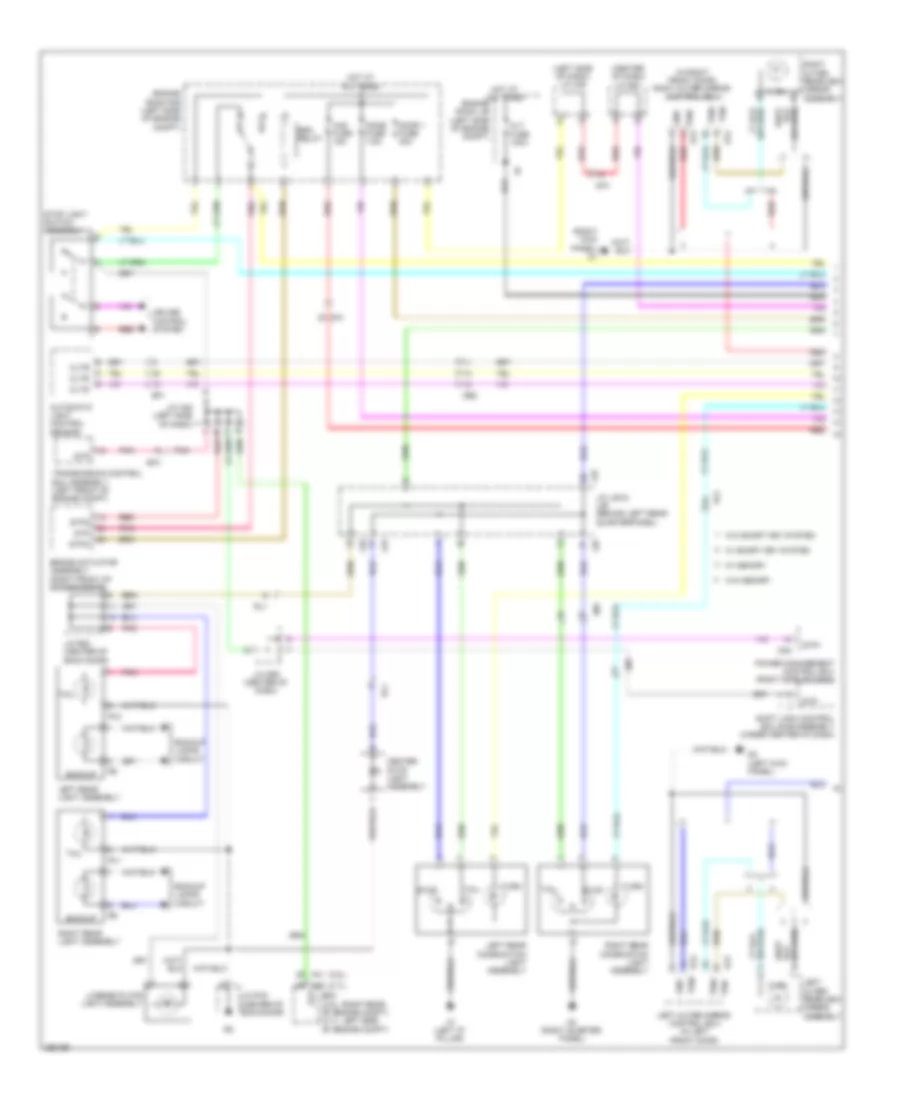
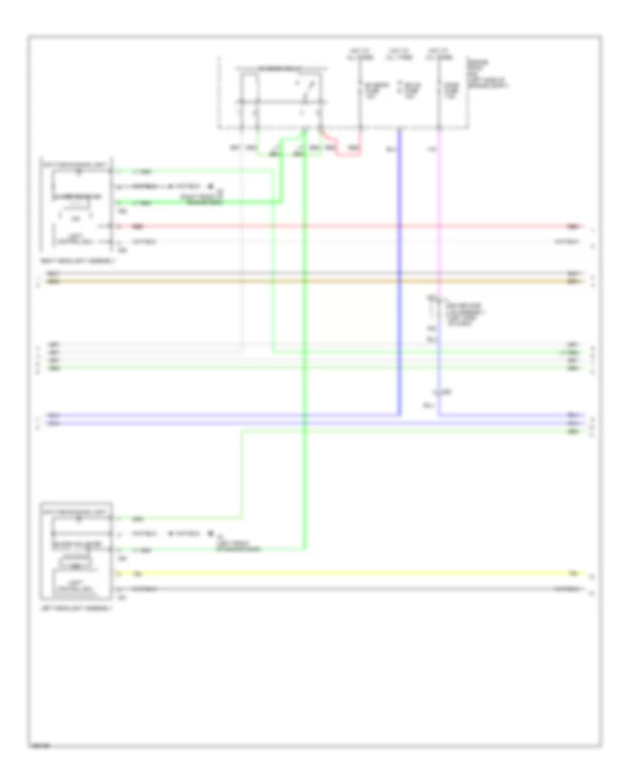
Exterior Lamps Wiring Diagram (2 of 2) for Toyota Venza LE 2013
List of elements for Exterior Lamps Wiring Diagram (2 of 2) for Toyota Venza LE 2013:
- (center of dash) j/c d58
- (center of dash) j/c d61
- (left end of dash) j/c d64
- (right front of engine room (engine room main wire)) a2
- A12
- A13
- A18
- A19
- A2 (right front of engine room (engine room main wire))
- A3 (left front of engine room (engine room main wire))
- A43
- A52
- A53
- Acc
- Altb
- Auto
- B+ dome
- Bcty
- C13
- C14
- C16
- C17
- C21
- C27
- C28
- C30
- Can i/f
- Canh
- Canl
- Cltb
- Clte
- Clts
- Combination meter assembly
- Computer data lines system
- D1 (right kick panel)
- D2 (left kick panel)
- D48
- D49
- D5 (right kick panel)
- D50
- D55
- D57
- Dcty
- De1
- De2
- Drive ic
- Drive monitor switch
- Driver's side j/b (left end of dash)
- Drl off (usa) off (except usa)
- E31
- Ecu ig 2 fuse 7.5a
- Ecu-acc fuse 7.5a
- Ecu-ig 1 fuse 10a
- F12
- F16
- F19
- F20
- F26
- G21
- G25
- G26
- G33
- Gauge 1 fuse 10a
- Gauge fuse 7.5a
- Gnd1
- H1 (left "d" pillar)
- Halogen type
- Hazard switch
- Hd1
- Head
- Headlight dimmer switch assembly
- Hid type
- Hot at all times
- Hot in on or start
- Hot w/ acc relay energized
- I1 (driver's door)
- Id1
- Id2
- Ig+
- Ind right turn
- Interior lights system
- J/c a43 & d55 (left side of dash)
- J/c d57 & e31 (center of dash)
- J/c d58 (center of dash)
- J/c d62 (center of dash)
- J/c e32 (right end of dash)
- K36
- Lcty
- Left
- Left headlight assembly
- Left turn ind
- Light control switch
- Main body ecu
- Micro processor
- O14
- O18
- O19
- Off
- Panel fuse 5a
- Parking
- Pcty
- Pnk
- Rcty
- Red
- Right
- Right headlight assembly
- Side marker
- Stop fuse 10a
- Tail
- Tail fuse 10a
- Tail ind (canada)
- Tail relay
- Trly
- Turn
- Turn signal flasher assembly (behind instrument cluster)
- Turn signal switch
GROUND DISTRIBUTION
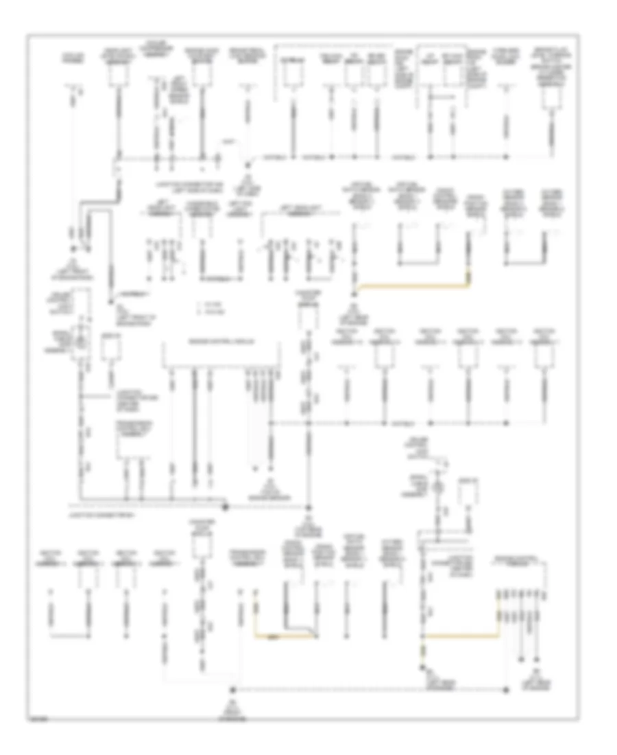
Ground Distribution Wiring Diagram (1 of 4) for Toyota Venza LE 2013
List of elements for Ground Distribution Wiring Diagram (1 of 4) for Toyota Venza LE 2013:
- (left front of engine room)
- (left rear of engine)
- (top of engine sensor)
- A/f relay
- A13
- A19
- A3 (3.5l)
- A38
- A4 (3.5l)
- A5 (3.5l) (left side of dash)
- A51
- A53
- Air fuel ratio sensor (bank 1 sensor 1) shield
- Air fuel ratio sensor (bank 2 sensor 1) shield
- B1 (3.5l)
- B2 (3.5l)
- B29
- B3 (3.5l) (top rear of engine)
- B39
- B4 (2.7l) (front of engine)
- B5 (2.7l) (left rear of engine)
- B58
- B6 (2.7l) (left rear of engine)
- Ba1
- Ba2
- Brake fluid level warning switch (brake master cylinder reservoir assembly)
- Brake pedal load sensing switch
- Canister pump module
- Cooler compressor assembly
- Cooling fan ecu
- Crank position sensor shield
- Cruise control main switch
- D18
- Da2
- Dlc 3
- Efi main relay
- Engine control module
- Engine hood courtesy switch
- Engine room j/b (left side of engine compt)
- Engine room r/b (left side of engine compt)
- Fan main relay
- Headlight leveling ecu assembly
- Ig2 relay
- Ignition coil assembly 1
- Ignition coil assembly 2
- Ignition coil assembly 3
- Ignition coil assembly 4
- Ignition coil assembly 5
- Ignition coil assembly 6
- Junction connector a46 (left side of dash)
- Junction connector b41
- Junction connector d59 (center of dash)
- Knock control sensor (bank 1) shield
- Knock control sensors shield
- La1
- Left fog light assembly
- Left front speed sensor shield
- Left headlight assembly
- Nca
- Oxygen sensor (bank 1 sensor 2) shield
- Oxygen sensor (bank 2 sensor 2) shield
- Rr def relay
- Spiral cable sub- assembly
- St relay
- Transmission control ecu assembly
- W/ hid
- W/o hid
- Windshield wiper motor assembly
- Wireless door lock buzzer
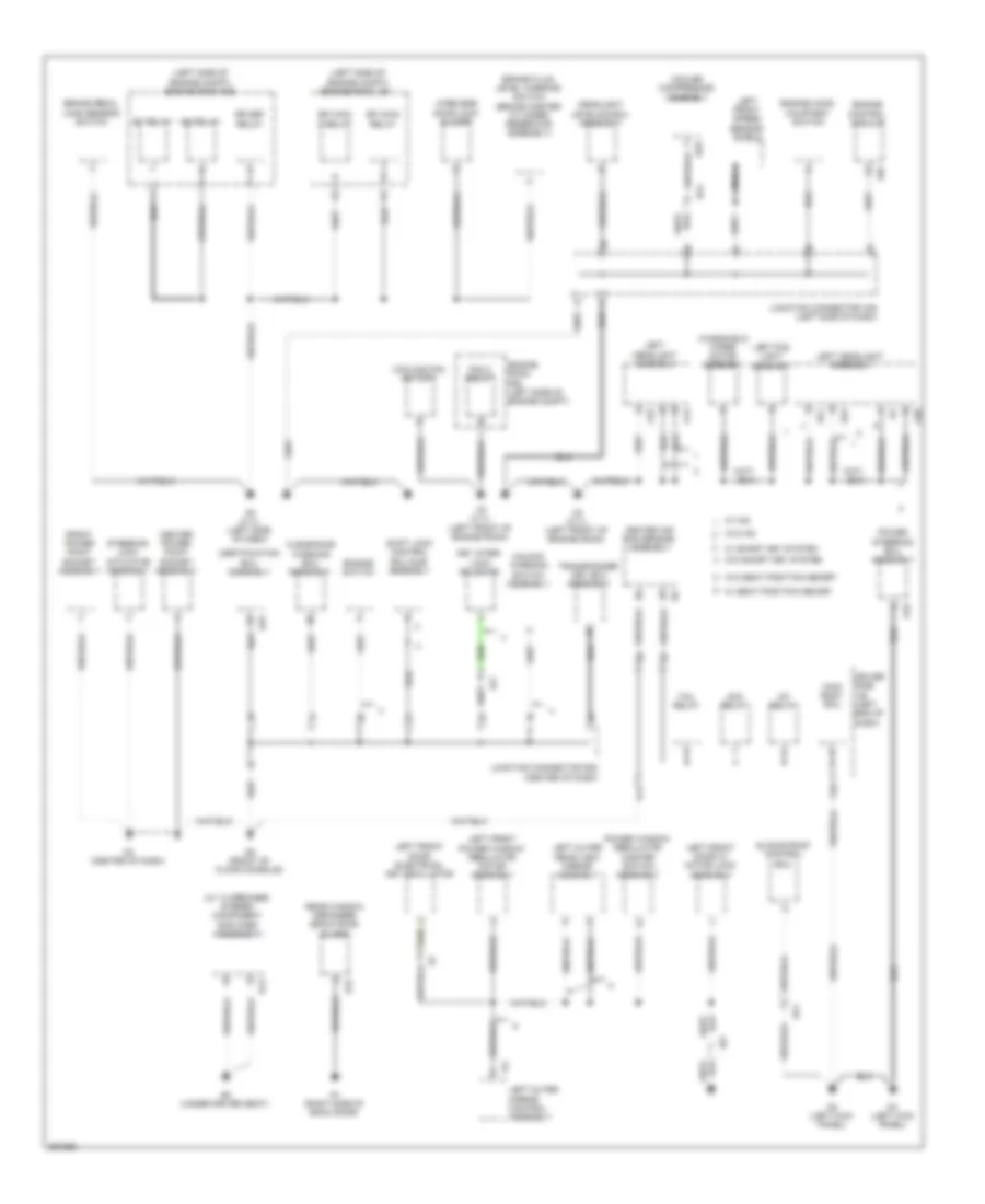
Ground Distribution Wiring Diagram (2 of 4) for Toyota Venza LE 2013
List of elements for Ground Distribution Wiring Diagram (2 of 4) for Toyota Venza LE 2013:
- (left side of engine compt) engine room j/b
- (left side of engine compt) engine room r/b
- (w/ 13 speaker) stereo component amplifier assembly
- A13
- A19
- A3 (2.7l) (left front of engine room)
- A38
- A4 (2.7l) (left front of engine room)
- A49
- A5 (2.7l) (left side of dash)
- A51
- A53
- Acc relay
- B29
- Ba1
- Brake fluid level warning switch (brake master cylinder reservoir assembly)
- Brake pedal load sensing switch
- Center air bag sensor assembly
- Center power point socket assembly
- Certification ecu assembly
- Clearance warning ecu assembly
- Cooler compressor assembly
- Cooling fan motor 2
- D19
- D2 (left kick panel)
- D25
- D3 (center of dash)
- D4 (left kick panel)
- D6 (front of floor console)
- Dp1
- Driver side j/b (left end of dash)
- Dz1
- E13
- E2 (under driver seat)
- Efi main 2 relay
- Efi main relay
- Engine control module
- Engine hood courtesy switch
- Engine room r/b (left side of engine compt)
- Engine switch
- F16
- Fan 2 relay
- Front power point socket assembly
- Headlight leveling ecu assembly
- I13
- Id2
- Ig1 relay
- Ig2 relay
- Iz1
- Junction connector a46 (left side of dash)
- Junction connector d63 (center of dash)
- K11
- Key inter- lock solenoid
- Left fog light assembly
- Left front door electrical key oscillator
- Left front door w/ motor lock assembly
- Left front power window regulator motor assembly
- Left front speed sensor shield
- Left headlight assembly
- Left outer mirror control assembly
- Left outer rear view mirror assembly
- Main body ecu
- Nca
- Power steering ecu assembly
- Power window regulator master switch assembly
- R1 (right side of back door)
- R15
- Rear window defogger (back door glass)
- Rr def relay
- Shift lock control ecu sub- assembly
- Sliding roof control ecu
- St relay
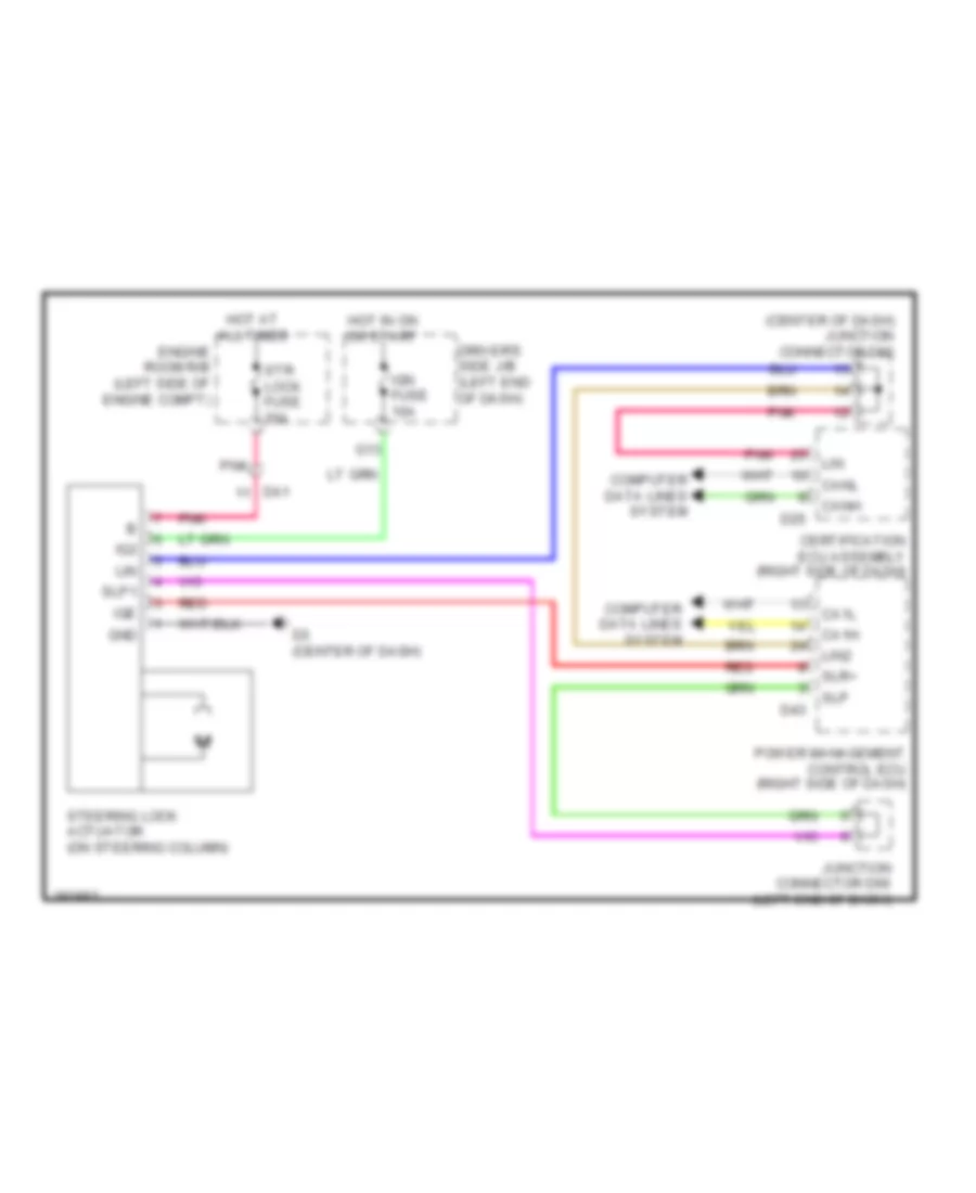
- Steering lock actuator assembly
- Tail relay
- Transponder key ecu assembly
- Unlock warning switch assembly
- W/ hid
- W/ seat position memory
- W/ smart key system
- W/o hid
- W/o seat position memory
- W/o smart key system
- Windshield wiper motor assembly
- Wireless door lock buzzer
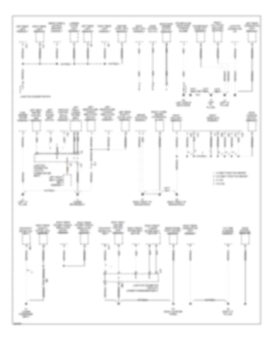
Ground Distribution Wiring Diagram (3 of 4) for Toyota Venza LE 2013
List of elements for Ground Distribution Wiring Diagram (3 of 4) for Toyota Venza LE 2013:
- A1 (right front of engine room)
- A12
- A18
- A2 (right front of engine room)
- A37
- A50
- A52
- Back door lock assembly
- Back door opener switch assembly
- Brake actuator assembly
- Center stop light assembly
- Door control receiver
- Door control switch
- Front multiplex network door ecu
- Front wiper deicer (windshield glass)
- Fuel sender gauge assembly
- Jm1
- Junction connector l24 & t9 (under driver seat)
- Junction connector l30
- Junction connector m26 & s14 (under passenger's seat)
- Junction connector r19
- Kl1
- L1 (under driver seat)
- L2 (left "d" pillar)
- L24
- L3 (left "c" pillar)
- L4 (left "d" pillar)
- Left front lumbar power seat switch
- Left front power seat switch
- Left front seat inner belt assembly
- Left rear combination light assembly
- Left rear door w/ motor lock assembly
- Left rear light assembly
- Left rear power window regulator motor assembly
- Left rear power window regulator switch assembly
- Left seat heater control sub assembly
- Level warning switch assembly
- License plate light assembly
- M1 (under passenger seat)
- M14
- M2 (right quarter panel)
- M26
- M3 (right "d" pillar)
- Occupant detection ecu
- Position control ecu & switch assembly
- Power back door unit assembly
- Power slide back door warning buzzer
- R11
- R12
- R2 (left side of back door)
- Rear power point socket assembly
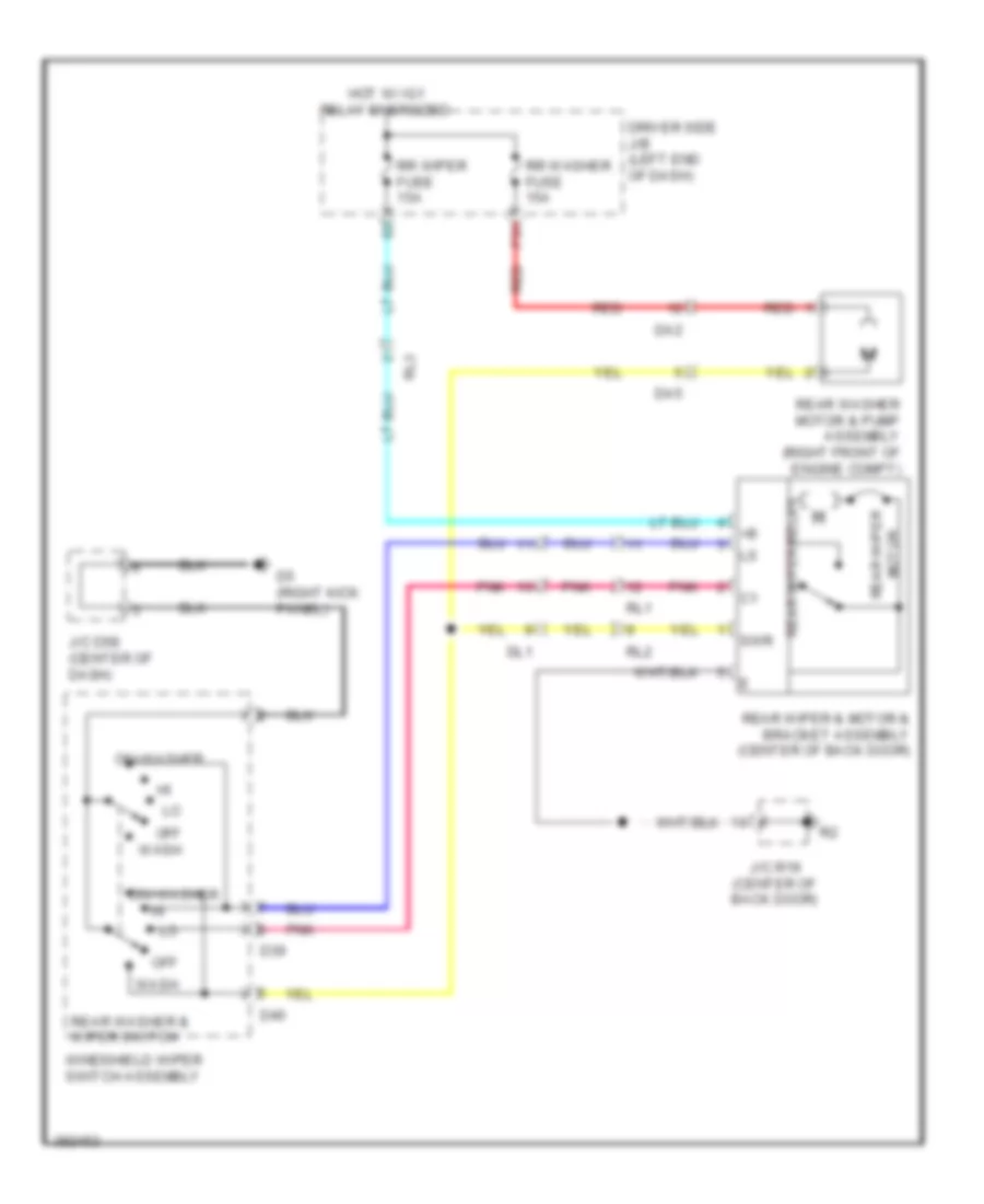
- Rear wiper & motor & bracket assembly
- Right fog light assembly
- Right front lumbar power seat switch
- Right front power seat switch
- Right headlight assembly
- Right rear combination light assembly
- Right rear door w/ motor lock assembly
- Right rear light assembly
- Right rear power window regulator motor assembly
- Right rear power window regulator switch assembly
- Right seat heater control sub- assembly
- Rl2
- S12
- S14
- T10
- Voltage inverter assembly
- W/ hid
- W/ seat position memory
- W/o hid
- W/o seat position memory
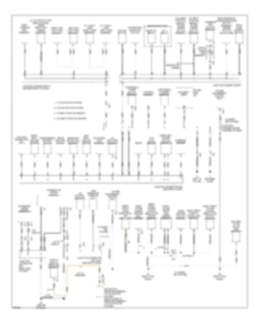
Ground Distribution Wiring Diagram (4 of 4) for Toyota Venza LE 2013
List of elements for Ground Distribution Wiring Diagram (4 of 4) for Toyota Venza LE 2013:
- (w/ automatic high beam system) inner rear view mirror assembly
- (w/ seat position memory) outer mirror switch assembly
- (w/ vanity lamp) left visor assembly
- (w/ vanity lamp) right visor assembly
- (w/o seat position memory) outer mirror switch assembly
- A/c amplifier assembly
- A/c control assembly
- Accessory meter assembly
- Awd ecu assembly
- Back door control switch
- Back sonar or clearance sonar switch assembly (spare switch hole cover)
- Blower w/ fan motor sub- assembly
- Combination meter assembly
- D1 (right kick panel)
- D18
- D39
- D43
- D47
- D5 (right kick panel)
- D57
- Dlc 3
- Dome cut relay
- Door control switch assembly
- Dp1
- Drive monitor switch
- Driver side j/b
- E1 (center of dash)
- E31
- E38
- E43
- Ef1
- Ef2
- Engine room r/b 3
- Glove box light assembly
- H1 (left "d" pillar)
- H13
- Hd1
- Headlight dimmer switch assembly
- Headlight swivel ecu assembly
- Hz1
- I1 (driver's door)
- Id2
- Ig1 2 relay
- Junction connector d57 & e31 (center of dash)
- Junction connector d58 (center of dash)
- Junction connector d62 (center of dash)
- Junction connector d67
- Junction connector d71
- Junction connector e32 (right end of dash)
- Junction connector p11 (center front of roof)
- K17
- Left map light sub- assembly
- Left seat heater switch
- Main body ecu
- Management control ecu
- Navigation receiver assembly (w/ navigation system) radio & display receiver assembly (w/o navigation system)
- Power
- Power back door main switch
- Power management control ecu
- Radio & display receiver assembly
- Right front door electrical key oscillator
- Right front door w/ motor lock assembly
- Right front power window regulator motor assembly
- Right front power window regulator switch assembly
- Right map light sub- assembly
- Right outer mirror control ecu assembly
- Right outer rear view mirror assembly
- Right seat heater switch
- Roof console box assembly
- Spiral cable sub- assembly
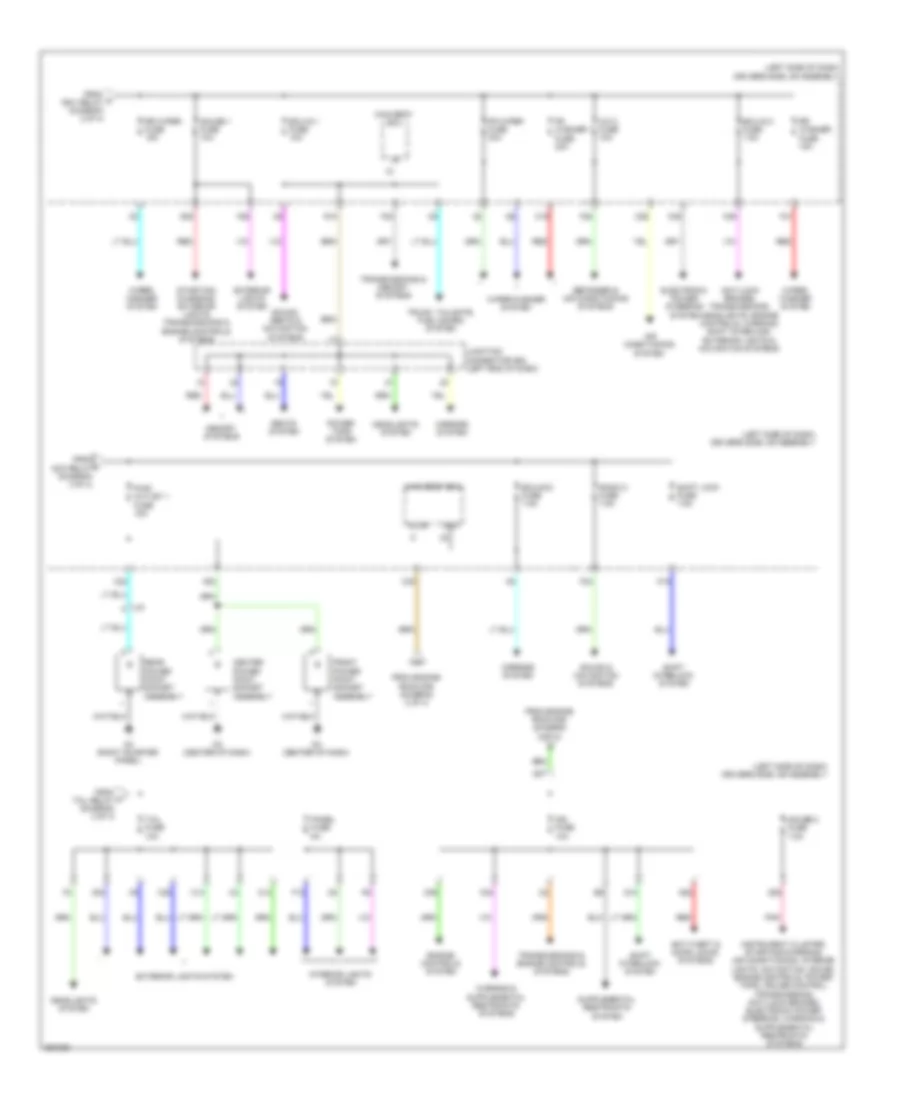
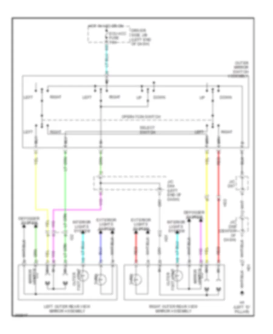
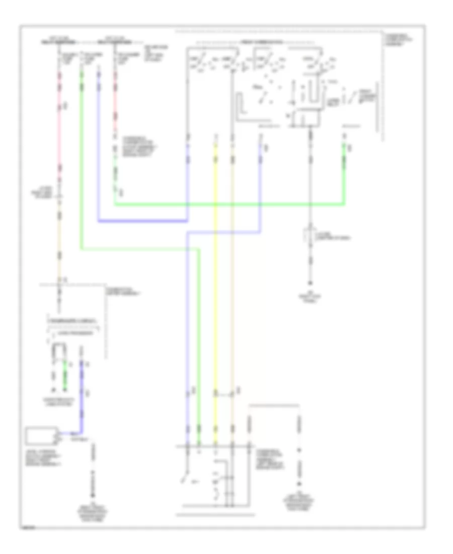
- Steering pad switch assembly
- Steering sensor
- Tft display
- Tire pressure warning ecu
- Transmission control switch
- Turn signal flasher assembly
- Vsc off switch
- W/ 13 speaker
- W/ 6 speaker
- W/ navigation system
- W/ retractor mirror
- W/ seat position memory
- W/ smart key system
- W/ tft display
- W/o navigation system
- W/o seat position memory
- Windshield wiper switch assembly
- Yaw rate sensor
HEADLIGHTS
Headlamp Beam Adjustment Wiring Diagram for Toyota Venza LE 2013
List of elements for Headlamp Beam Adjustment Wiring Diagram for Toyota Venza LE 2013:
- (left front of engine room) a4
- (left side of dash) j/c a45
- (left side of dash) j/c a46
- A16
- A17
- A43
- Ae1
- Brake actuator assembly (right front of engine compt)
- Circuit
- Combination meter assembly
- D1 (right kick panel)
- D55
- D57
- Da1
- De2
- Dlc 3
- Driver side j/b assembly (left end of dash)
- E31
- Ecu ig 2 fuse 7.5a
- G12
- G25
- G35
- Gauge 2 fuse 7.5a
- Headlight beam level ind
- Headlight leveling ecu assembly (left side of dash)
- Height control sensor sub-assembly (rear of vehicle)
- Hot in on or start
- Hrly
- Ig+
- Ig2
- Init
- J/c a43 & d55 (left side of dash)
- J/c d57 & e31 (center of dash)
- J/c d60 (center of dash)
- J/c d61 (center of dash)
- J/c d63 (center of dash)
- J/c e32 (right end of dash)
- K36
- Left headlight assembly
- Leveling mtr headlight
- Lh+
- Lh-
- Lhm+
- Lhm-
- Lht
- Lvl
- Lvwg
- Ma1
- Main body ecu
- Nm1
- Pnk
- Processor micro
- Prst
- Red
- Rh+
- Rh-
- Rhm+
- Rhm-
- Rht
- Right headlight assembly
- Sbr
- Sgr
- Shb
- Shg
- Shrl
- Shrr
- Sil
- Sp1
- Spdr
- Wng
Headlamps Wiring Diagram (1 of 3) for Toyota Venza LE 2013
List of elements for Headlamps Wiring Diagram (1 of 3) for Toyota Venza LE 2013:
- (center of dash) j/c d58
- (left kick panel) d2
- A2 (right front of engine room)
- A3 (left front of engine room)
- Acc
- Auto
- Automatic light control sensor (w/ automatic high beam)
- Bcty
- Becu
- C12
- C23
- C24
- Canh
- Canl
- Cltb
- Clte
- Clts
- Computer data lines system
- D48
- D49
- D5 (right kick panel)
- D50
- D51
- Dcty
- De2
- Dim
- Dimmer switch
- Driver side j/b assembly (left side of dash)
- Drl
- Drl off
- Ecu-acc fuse 7.5a
- Ecu-ig 1 fuse 10a
- Ef1
- Except usa
- F16
- Ffgo
- Ffog
- Flash
- Fog relay
- Fog switch
- Fr fog fuse 15a
- G28
- G35
- Gnd1
- Gnd2
- Head
- Headlamp dimmer switch assembly
- High
- Hot at all times
- Hot in on or acc
- Hot in on or start
- Hrly
- Interior lights system
- J/c d58 (center of dash)
- J/c d62 (center of dash)
- K17
- La1
- Lcty
- Left fog light assembly
- Light control switch
- Low
- Main body ecu (left side of dash)
- O19
- Off
- Park brake switch assembly
- Pcty
- Pkb
- Pnk
- R10
- Rcty
- Red
- Right fog light assembly
- Tail
- Tail fuse 10a
- Tail relay
- Trly
- Usa
Headlamps Wiring Diagram (2 of 3) for Toyota Venza LE 2013
List of elements for Headlamps Wiring Diagram (2 of 3) for Toyota Venza LE 2013:
- A2 (right front of engine room)
- A3 (left front of engine room)
- A50
- A51
- A52
- A53
- Bi-xen0n fuse 10a
- Bi-xen0n relay
- C27
- Daytime running light
- De1
- Dome fuse 7.5a
- Driver side j/b assembly (left side of dash)
- Ecu-b fuse 10a
- Engine room r/b (left side of engine compt)
- F20
- Hid
- Hot at all times
- Left headlight assembly
- Light control ecu
- Red
- Right headlight assembly
- Shade adjuster
Headlamps Wiring Diagram (3 of 3) for Toyota Venza LE 2013
List of elements for Headlamps Wiring Diagram (3 of 3) for Toyota Venza LE 2013:
- (center of dash) j/c d58
- (center of dash) j/c d61
- (center of dash) j/c d62
- +b (dome)
- A2 (right front of engine room)
- A3 (left front of engine room)
- A37
- A38
- A43
- Alt fuse 140a
- Auto ind (w/ automatic high beam system)
- Beam ind
- Can i/f
- Canh
- Canl
- Combination meter assembly
- Computer data lines system
- D1 (right kick panel)
- D5 (right kick panel)
- D55
- D57
- Da1
- Dlc 3
- Dp1
- Drive ic
- E31
- Engine room j/b (left side of engine compt)
- F15
- F16
- F17
- Front fog ind
- H-lp hi (drl) relay
- H-lp hi (lh) fuse 15a
- H-lp hi (rh) fuse 15a
- H-lp lo (lh) fuse 15a
- H-lp lo (lh) relay
- H-lp lo (rh) fuse 15a
- H-lp lo (rh) relay
- Halogen
- Halogen type
- Head ind (usa)
- Headlight swivel ecu assembly (w/ automatic high beam system) (center of dash)
- Hid type
- High
- Hot at all times
- Ig2
- Inner rear view mirror assembly
- J/c d55 & a43 (left side of dash)
- J/c d57 & e31 (center of dash)
- J/c d64 (left end of dash)
- Left headlight assembly
- Light control circuit
- Lin
- Low
- Lvl
- Micro processor
- Mpx2
- Red
- Right headlight assembly
- Smr
- Solid state
HORN
Horn Wiring Diagram for Toyota Venza LE 2013
List of elements for Horn Wiring Diagram for Toyota Venza LE 2013:
- C25
- D18
- Driver's side j/b (left end of dash)
- Engine room j/b (left side of engine compartment)
- G11
- High pitched horn assembly (front of engine compartment)
- Horn
- Horn fuse 10a
- Horn relay
- Horn switch
- Hot at all times
- Low pitched horn assembly (front of engine compartment)
- Main body ecu
- Red
- Spiral cable (steering column)
- Steering pad switch
INSTRUMENT CLUSTER
Instrument Cluster Wiring Diagram (1 of 3) for Toyota Venza LE 2013
List of elements for Instrument Cluster Wiring Diagram (1 of 3) for Toyota Venza LE 2013:
- (a/t position)
- (canada)
- (center of dash)
- (center of dash) e1
- (center of dash) j/c d57 & e31
- (left end of dash) driver's side j/b
- (right kick panel) d1
- (usa)
- +b (dome)
- +b(dome)
- A2 (right of front engine room)
- A5 (left side of dash)
- Abs ind
- Ae1
- Anti-lock brakes system
- Auto ind (if equipped)
- Awd
- Ba1
- Beam ind
- Brake fluid level warning switch (on brake fluid reservoir)
- Brake ind
- Buzzer
- C24
- C27
- Can i/f
- Charge ind
- Combination meter assembly
- Computer data lines system
- Cruise ind
- D57
- De1
- Dome fuse 7.5a
- Door 1 fuse 25a
- Door ind
- Drive ic
- Driver's seat belt ind
- E31
- Ecu-b fuse 10a
- Ef1
- Ef2
- Engine oil pressure switch assembly (2.7l: left side of engine) (3.5l: lower left front of engine compt)
- Engine room r/b (left side of engine compt)
- Exterior lights system
- F20
- Front fog ind
- Fuel gauge
- Fuel ind
- Fuel sender gauge assembly (under left side of rear seat)
- Gauge
- Head ind
- Headlight beam level ind
- Headlights systems
- Hot at all times
- If equipped
- Ig2
- Illumination
- Illumination lcd
- Illumination pointer
- Interior lights system
- J/c d57 & e31 (center of dash)
- J/c e31 & d57
- J/c e32 (right end of dash)
- Lcd
- Lcd (odo/ trip)
- Lcd display
- Le1
- Left turn ind
- Level warning switch assembly (right front engine assembly)
- Lm1
- Maint reqd ind (usa)
- Me1
- Micro processor
- Oil press ind
- Pnk
- Red
- Rheostat/ trip reset
- Right turn ind
- Set ind
- Speedometer
- Srs ind
- Starting/ charging system
- Sub fuel sender gauge assembly (top of fuel tank)
- Sw b+
- Tachometer
- Tail ind
- Temperature gauge
- Tft display
- W/ navigation system
- Warning systems
Instrument Cluster Wiring Diagram (2 of 3) for Toyota Venza LE 2013
List of elements for Instrument Cluster Wiring Diagram (2 of 3) for Toyota Venza LE 2013:
- (center of dash) j/c d61 & d60
- (center of dash) j/c d63
- (left end of dash)
- (left end of dash) j/c d66
- (right kick panel) d5
- 2.7l
- 3.5l
- A41
- A43
- A49
- Acc
- Altb
- Awd
- Ba1
- Bcty
- Becu
- C24
- C30
- Canh
- Canl
- Clock
- Computer
- D43
- D48
- D49
- D50
- D51
- D55
- D57
- D58
- D6 (front of floor console)
- D60
- D61
- D62
- D66
- Dcty
- De2
- Dl1
- Dm2
- Drive monitor switch
- Driver side j/b
- E14
- E31
- E40
- E42
- Ecm (2.7l: left side of engine compt) (3.5l: right rear of engine compt)
- Ecu- acc fuse 7.5a
- Ecu- ig 1 fuse 10a
- Headlight leveling ecu assembly (left side of dash)
- Hot in on or acc
- Hot in on or start
- If equipped
- Info
- Info info
- J/c a43 & d55 (left side of dash)
- J/c d57 & e31 (center of dash)
- J/c d62 & d58 (center of dash)
- Ksw
- La1
- Lcd display
- Lcty
- Left front door courtesy light switch
- Left rear door courtesy light switch
- Main body ecu
- Navigation receiver assembly (w/ navigation) radio & display receiver assembly (w/o navigation)
- O19
- Park brake switch assembly
- Pcty
- Pkb
- Pnk
- Power management control ecu (w/ smart key system) (right side of dash)
- Rcty
- Red
- Reset
- Right front door courtesy switch
- Right rear door courtesy light switch
- Sel reset h
- Select
- Spd
- Spdr
- Stereo component amplifier assembly (if equipped) (under driver's seat)
- Stup setup
- Sut
- System data lines
- Tft display
- Tire pressure warning ecu (behind glove box)
- Transmission control ecu assembly (left front of engine compt)
- Un-lock warning switch assembly (w/o smart key system)
- Us/m m
- W/ navigation
- W/o navigation
Instrument Cluster Wiring Diagram (3 of 3) for Toyota Venza LE 2013
List of elements for Instrument Cluster Wiring Diagram (3 of 3) for Toyota Venza LE 2013:
- (behind left rear quarterpanel) j/c l25 & l26
- (center of back door) back door lock assembly
- (lcd display) micro
- Accessory meter assembly
- Air bag off ind
- Air bag on ind
- Anti-theft system
- Awd
- Awd ind
- Chk
- Courtesy
- Data
- De2
- Dl1
- Door locks & anti-theft systems
- Driver side j/b (left end of dash)
- E1 (center of dash)
- Ef1
- Ef2
- Engine controls system
- Front passenger's seat belt ind
- G25
- Gauge 2 fuse 7.5a
- Hot in on or start
- Hsi+
- If equipped
- Ig+
- Ig2
- Ill+
- Illumination lcd
- J/c c32
- J/c r19 (center of back door)
- L25
- L26
- Lcd
- Lcd display
- Master smart key ind
- Multi-funtion ind lamp
- P/ab
- Paon
- Pbew
- Pnk
- Power steering ind
- Red
- Rl1
- Sec
- Security ind
- Sg1
- Sg2
- Sg3
- Sg4
- Sg5
- Sg6
- Sg7
- Sg8
- Sgnd
- Slip ind
- Sync
- Tft display
- Tft module (tft display)
- Tire press ind
- Trac off ind
- Vsc off ind
- W/ back door closer & w/o power back door
- W/o back door closer & w/o power back door
- Washer level ind
INTERIOR LIGHTS
Courtesy Lamps Wiring Diagram (1 of 2) for Toyota Venza LE 2013
List of elements for Courtesy Lamps Wiring Diagram (1 of 2) for Toyota Venza LE 2013:
- Acc
- Altb
- Bcty rcty pcty d49
- Becu
- C24
- C27
- C30
- Canh canl d48
- Computer data lines system
- D2 (left kick panel)
- D6 (front of floor console)
- Dcty d50
- Diode (left front door courtesy light)
- Diode (right front door courtesy light)
- Dl1
- Dl2
- Dm2
- Dome cut relay
- Dome fuse 7.5a
- Domr
- Door 1 fuse 20a
- Dp1
- Driver side j/b (left side of dash)
- Ecu ig 1 fuse 10a
- Ecu-acc fuse 7.5a
- Ecu-b fuse 10a
- Engine room r/b (left side of engine compt)
- F13
- F16
- Gnd1
- Gnd2
- H1 (left "d" pillar)
- Hd1
- Hd2
- Hot at all times
- Hot in on or acc
- Hot in on or start
- Id2
- Ignition key cylinder light ind
- Ile
- J/c d58 (center of dash)
- Junction connector d60 (center of dash)
- Junction connector d61 (center of dash)
- Junction connector d63 (center of dash)
- Junction connector d66 (left end of dash)
- K17
- Ksw d51
- Lcty
- Left front door courtesy light assembly
- Left front door courtesy light switch
- Main body ecu (left side of dash)
- O19
- Pnk
- R/b 3 (left side of dash)
- Red
- Right front door courtesy light assembly
- Right front door courtesy light switch
- Right rear door courtesy light switch
- Transponder key amplifier (w/o smart key system) (right side of steering column)
- Un lock warning switch assembly (w/o smart key system)
Courtesy Lamps Wiring Diagram (2 of 2) for Toyota Venza LE 2013
List of elements for Courtesy Lamps Wiring Diagram (2 of 2) for Toyota Venza LE 2013:
- (behind left rear quarterpanel) j/c l25 & l26
- (center front of roof) junction connector p11
- (center of dash) junction connector d58
- (in left front door) left outer mirror control ecu assembly
- (in right front door) right outer mirror control ecu assembly
- Back door lock assembly (center of back door)
- Cann
- Canp
- Computer data lines system
- Courtesy
- Cty
- D5 (right kick panel)
- Diode (back door courtesy switch)
- Dl1
- Door
- Dp1
- Gnd
- H12
- H13
- Htr-
- I1 (driver's door)
- I12
- I13
- Id2
- Junction connector d58 (center of dash)
- Junction connector d67
- Junction connector l25 & l26 (behind left rear quarterpanel)
- Junction connector r19 (center of back door)
- L25
- L26
- Left map light sub assembly
- Left outer rear view mirror assembly
- Left rear door courtesy light switch
- Left vanity light assembly (if equipped)
- Left visor assembly (w/ vanity light)
- Map light
- Mlp
- Off
- Outer foot light
- Pnk
- Red
- Right map light sub assembly
- Right outer rear view mirror assembly
- Right vanity light assembly (if equipped)
- Right visor assembly (w/ vanity light)
- Rl1
- Roof console box assembly
- Room light assembly 2
- W/ seat position memory
Instrument Illumination Wiring Diagram (1 of 2) for Toyota Venza LE 2013
List of elements for Instrument Illumination Wiring Diagram (1 of 2) for Toyota Venza LE 2013:
- (right kick panel) d5
- Acc
- Alt fuse 140a
- Altb
- Auto
- Back door control switch
- Back sonar/ clearance sonar switch assembly (spare switch hole cover) (w/ parking assist)
- Becu
- C24
- C27
- C30
- Canada
- Canh
- Canl
- Canl canh d48
- Certification ecu assembly (w/ smart key system) (right side of dash)
- Computer data lines system
- D2 (left kick panel)
- D25
- D57
- D6 (front of floor console)
- De1
- Dl1
- Dome fuse 7.5a
- Door 1 fuse 20a
- Door control switch
- Driver side j/b (left side of dash)
- Drl off off
- E31
- Ecu ig 1 fuse 10a
- Ecu-acc fuse 7.5a
- Ecu-b fuse 10a
- Engine room j/b (left side of engine compt)
- Engine room r/b (left side of engine compt)
- Engine switch (w/ smart key system)
- F12
- F13
- F16
- F20
- Gnd1
- Gnd2
- Head
- Headlight dimmer switch assembly
- Hot at all times
- Hot w/ acc relay energized
- Hot w/ ig1 relay energized
- I1 (driver's door)
- Id2
- Ignition key cylinder light ind
- Ile
- Ill+
- Ill-
- Indicator light wire sub assembly
- Junction connector d57 & e31 (center of dash)
- Junction connector d58 (center of dash)
- Junction connector d62 (center of dash)
- Junction connector d63 (center of dash)
- Junction connector d65 (left end of dash)
- K17
- Light control switch
- Main body ecu (left side of dash)
- Panel fuse 5a
- Pnk
- Power back door main switch
- Red
- Rl1
- Rl2
- Swil
- Tail
- Tail d50
- Tail relay
- Transponder key amplifier (right side of steering column)
- Trly
- Usa
- Vsc off switch
Instrument Illumination Wiring Diagram (2 of 2) for Toyota Venza LE 2013
List of elements for Instrument Illumination Wiring Diagram (2 of 2) for Toyota Venza LE 2013:
- (13 speaker w/ navigation) navigation receiver assembly (13 speaker w/o navigation & 6 speaker) radio & display receiver assembly
- +b (dome)
- 13 speaker
- 13 speaker w/o navigation
- 6 speaker
- A/c control assembly
- Accessory meter assembly
- Back ind
- Canh
- Canl
- Combination meter assembly
- Computer data lines system
- D1 (right kick panel)
- D18
- D57
- Down ind
- Drive monitor switch
- Driver side j/b (left side of dash)
- Dz2
- E1 (center of dash)
- E31
- E38
- E39
- E43
- Ef2
- Enter ind
- F14
- Front console box illumination light assembly
- Glove box light assembly
- Gnd
- H1 (left "d" pillar)
- Hd1
- I/f can
- I1 (driver's door)
- Id2
- Ig2/dome b+
- Ill+
- Ill-
- Illumination
- Junction connector d57 & e31 (center of dash)
- Junction connector d58 (center of dash)
- Junction connector d60 (center of dash)
- Junction connector d61 (center of dash)
- Junction connector d62 (center of dash)
- Junction connector d67
- Junction connector e32 (right side of dash)
- Lcd illumination
- Left ind
- Left seat heater switch (if equipped)
- Left steering pad switch
- Micro processor
- Mode ind
- Off hook ind
- On hook ind
- Pnk
- Pointer illumination
- R11
- Rear console box illumination light assembly
- Right ind
- Right seat heater switch (if equipped)
- Right steering pad switch
- Spiral cable
- Steering pad switch assembly
- Up ind
- Voice ind
- Volume+ ind
- Volume- ind
- W/ navigation
MEMORY SYSTEMS
Memory Mirrors Wiring Diagram for Toyota Venza LE 2013
List of elements for Memory Mirrors Wiring Diagram for Toyota Venza LE 2013:
- (in right front door) right outer mirror control ecu
- (left kick panel) d2
- A43
- Altb
- Bdr
- C24
- C30
- Canh
- Canl
- Cann
- Canp
- Computer data lines system
- Cpub
- D1 (right kick panel)
- D48
- D5 (right kick panel)
- D50
- D55
- Door 1 fuse 20a
- Down
- Driver side j/b (left end of dash)
- Driver's side j/b (left end of dash)
- Ecu-b fuse 10a
- Ecu-ig 1 fuse 10a
- Engine room r/b (left side of engine compt)
- Exterior lights system
- F23
- Fold
- Gnd
- H12
- H13
- Hd1
- Hd2
- Hot at all times
- Hot in on or start
- Hsrl
- Hssr
- Htr-
- I12
- I13
- Id1
- Interior lights system
- J/c a43 & d55 (left side of dash)
- J/c d57 (right side of dash
- J/c d58 (center of dash)
- J/c d59 (center of dash)
- J/c d59 (w/ retractor mirror) (center of dash)
- J/c d61 (center of dash)
- J/c d64 (left end of dash)
- J/c d67
- Le1
- Left
- Left outer mirror control ecu (in left front door)
- Left outer rear view mirror assembly
- Lm+r
- Lmhr
- Lmvr
- Lvc
- Main body ecu
- Mirb
- Mire
- Mirror
- Mirror fuse 10a
- Mirs
- Mry
- Msw
- Mswe
- Outer foot light
- Outer mirror switch
- Pnk
- R10
- Re1
- Red
- Right
- Right outer rear view mirror assembly
- Rm+r
- Rmhr
- Rmvr
- Rvc
- Seat memory switch
- Set
- Sig
- Trn+
- Trn-
- Trni
- Turn
- Unfold
- Vsrl
- Vssr
- W/ retractor
Memory Seat Wiring Diagram for Toyota Venza LE 2013
List of elements for Memory Seat Wiring Diagram for Toyota Venza LE 2013:
- Buckle switch
- C24
- Cann
- Canp
- Computer data lines system
- Cpub
- D2 (left kick panel)
- Dbcl
- Dl2
- Driver side j/b (left end of dash)
- Ecu ig 1 fuse 10a
- Ecu-b fuse 10a
- Engine room r/b (left side of engine compt)
- Front
- Frv+
- Frv-
- Gnd
- Hot at all times
- Hot in on or start
- I13
- Id1
- J/c d57 (right side of dash)
- J/c d59 (center of dash)
- J/c d64 (left end of dash)
- J/c l24 & t9 (under driver's seat)
- J/c t9 & l24 (under driver's seat)
- L1 (under driver seat)
- L24
- Left front lumbar power seat switch
- Left front lumbar support forward & back motor assembly
- Left front power seat lift position motor assembly
- Left front power seat reclining position motor assembly
- Left front power seat side position motor assembly
- Left front power seat vertical position motor assembly
- Left front seat inner belt assembly (integral to left front seat belt buckle assembly)
- Left outer mirror control ecu (in left front door)
- Lft+
- Lft-
- Mry
- Mswe
- O/p
- O10
- P/seat fuse 30a
- Pnk
- Position control ecu & switch assembly
- Pvcc
- R10
- Rcl+
- Rcl-
- Rdc
- Rear
- Red
- Seat memory switch
- Set
- Sgnd
- Sig
- Sld+
- Sld-
- Slide sensor
- Ssrs
- Sysb
- T10
- T11
- T13
- Vcc
NAVIGATION
Navigation Wiring Diagram, 13-Speaker with Navigation Receiver Type (1 of 4) for Toyota Venza LE 2013
List of elements for Navigation Wiring Diagram, 13-Speaker with Navigation Receiver Type (1 of 4) for Toyota Venza LE 2013:
- (center of dash) e1
- +b1
- Acc1
- Ae1
- Ca+
- Cb+
- Cgnd
- Cv+
- Cv-
- D57
- De2
- Driver side j/b (left end of dash)
- E38
- E39
- E41
- Engine room r/b (left side of engine compt)
- F24
- Fl+
- Fl-
- Fr+
- Fr-
- Gnd1
- Gps antenna
- Hot at all times
- Hot w/ acc relay energized
- Ill+
- Ill-
- Interior lights system
- J/c d57 & e31 (center of dash) e31
- K10
- La1
- Le1
- Main antenna
- Navigation receiver assembly
- Nca
- Parking brake switch assembly
- Pkb
- Pnk
- Radio 1 fuse 20a
- Radio 2 fuse 7.5a
- Rear television camera assembly (center of back door)
- Red
- Rl+
- Rl-
- Rl1
- Sdars antenna
- Sub antenna
Navigation Wiring Diagram, 13-Speaker with Navigation Receiver Type (2 of 4) for Toyota Venza LE 2013
List of elements for Navigation Wiring Diagram, 13-Speaker with Navigation Receiver Type (2 of 4) for Toyota Venza LE 2013:
- (if equipped) voice
- 2.7l
- 3.5l
- Adpg
- Ae1
- Agnd
- B39
- B58
- Back
- Can+
- Can-
- Canh
- Canl
- Computer data lines system
- D18
- De1
- De2
- Down
- Driver side j/b (left end of dash)
- E40
- E47
- Ecm (3.5l: right rear of engine compt) (2.7l: left side of engine compt)
- Ecu ig 1 fuse 10a
- Enter
- G38
- Gauge 1 fuse 10a
- Hot w/ ig1 relay energized
- Left
- Left steering pad switch
- Macc
- Min+
- Min-
- Mode
- Mut1
- Navigation receiver assembly
- Nca
- Off hook
- On hook
- Park/neutral position switch (top of transmission)
- Red
- Right
- Right steering pad switch
- Sgnd
- Sns2
- Spd
- Spiral cable sub-assembly (steering column)
- Steering pad switch assembly
- Sw1
- Sw2
- Sw3
- Swg
- Transmission control ecu assembly (left front of engine compt)
- Tx1+
- Tx1-
- Va-
- Val+
- Var+
- Vol+
- Vol-
Navigation Wiring Diagram, 13-Speaker with Navigation Receiver Type (3 of 4) for Toyota Venza LE 2013
List of elements for Navigation Wiring Diagram, 13-Speaker with Navigation Receiver Type (3 of 4) for Toyota Venza LE 2013:
- Acc
- Ae1
- Brake actuator assembly (right front of engine compt)
- C24
- C27
- Can i/f
- Canh
- Canl
- Combination meter assembly
- Computer data lines system
- D1 (right kick panel)
- D57
- De1
- De2
- Dome fuse 7.5a
- Driver side j/b (left end of dash)
- E31
- Ecu-b fuse 10a
- Ee1
- Engine room r/b (left side of engine compt)
- Ep1
- F20
- G25
- Gauge 2 fuse 7.5a
- Hot at all times
- Hot w/ ig2 relay energized
- Ig+
- Ig2
- Inner rear view mirror assembly
- J/c d57 & e31 (center of dash)
- J/c e31 (center of dash)
- J/c e32 (right end of dash)
- Mic+
- Mic-
- Micro processor
- Microphone amplifier
- Nca
- Pnk
- Red
- Right front speaker assembly 2
- Right front speaker assembly 3
- Sgnd
- Sp1
- Stereo jack adapter assembly 1
- Twr+
- Twr-
Navigation Wiring Diagram, 13-Speaker with Navigation Receiver Type (4 of 4) for Toyota Venza LE 2013
List of elements for Navigation Wiring Diagram, 13-Speaker with Navigation Receiver Type (4 of 4) for Toyota Venza LE 2013:
- +b2
- Acc
- Ae1
- Audio amp fuse 20a
- Ctr+
- Ctr-
- De1
- De2
- E12
- E13
- E14
- E15
- E2 (under driver seat)
- Engine room r/b (left side of engine compt)
- Fl+
- Fl-
- Fr+
- Fr-
- Front speaker assembly 4
- Gnd
- Gnd2
- Hd2
- Hot at all times
- Id2
- Ii1+
- Ii1-
- Jm1
- Kl1
- Le1
- Left front speaker assembly 1
- Left front speaker assembly 2
- Left front speaker assembly 3
- Left rear speaker assembly
- Left rear speaker assembly 2
- Left rear speaker assembly 3
- Me1
- Me2
- Mute
- Nca
- Pnk
- Red
- Right front speaker assembly 1
- Right rear speaker assembly
- Right rear speaker assembly 2
- Right rear speaker assembly 3
- Rl+
- Rl-
- Rr+
- Rr-
- Sl+
- Sl-
- Sld
- Sld1
- Spd
- Sr+
- Sr-
- Stereo component amplifier assembly (under driver's seat)
- Twl+
- Twl-
- Tx+
- Tx-
- Wf1+
- Wf1-
- Wf2+
- Wf2-
- Wfl+
- Wfl-
- Wfr+
- Wfr-
Navigation Wiring Diagram, 13-Speaker without Navigation Receiver Type (1 of 4) for Toyota Venza LE 2013
List of elements for Navigation Wiring Diagram, 13-Speaker without Navigation Receiver Type (1 of 4) for Toyota Venza LE 2013:
- Acc
- Ae1
- Agnd
- Avc+
- Avc-
- Ca+
- Cgnd
- De2
- Driver side j/b (left end of dash)
- E44
- E50
- Ecu ig 1 fuse 10a
- Extension module (if equipped) (center of dash)
- G38
- Gauge 1 fuse 10a
- Gps antenna
- Hot w/ ig1 relay energized
- Hsyn
- K10
- La1
- Le1
- Main antenna
- Mic+
- Mic-
- Mute
- Nca
- Parking brake switch assembly
- Pkb
- Pnk
- Radio & display receiver assembly
- Rear television camera assembly (center of back door)
- Red
- Red cv+
- Rl1
- Sdars antenna
- Shd1
- Shd2
- Shd3
- Spd
- Sub antenna
- V-b
- V-g
- V-r
- Vol+
- Vol-
- Vshd
- Vsyn
Navigation Wiring Diagram, 13-Speaker without Navigation Receiver Type (2 of 4) for Toyota Venza LE 2013
List of elements for Navigation Wiring Diagram, 13-Speaker without Navigation Receiver Type (2 of 4) for Toyota Venza LE 2013:
- 2.7l
- 3.5l
- Adpg
- Agnd
- B39
- B58
- Back
- Can+
- Can-
- Canh
- Canl
- Computer data lines system
- D18
- De1
- De2
- Down
- E42
- E48
- Ecm (3.5l: right rear of engine compt) (2.7l: left side of engine compt)
- Enter
- Left
- Left steering pad switch
- Macc
- Min+
- Min-
- Mode
- Nca
- Off hook
- On hook
- Park/neutral position switch (top of transmission)
- Radio & display receiver assembly
- Red
- Right
- Right steering pad switch
- Sgnd
- Sns2
- Spd
- Spiral cable sub-assembly (steering column)
- Steering pad switch assembly
- Sw1
- Sw2
- Sw3
- Swg
- Transmission control ecu assembly (left front of engine compt)
- Va-
- Val+
- Var+
- Voice
- Vol+
- Vol-
- W/ extension module
- W/o extension module
Navigation Wiring Diagram, 13-Speaker without Navigation Receiver Type (3 of 4) for Toyota Venza LE 2013
List of elements for Navigation Wiring Diagram, 13-Speaker without Navigation Receiver Type (3 of 4) for Toyota Venza LE 2013:
- Acc
- Ae1
- Brake actuator assembly (right front of engine compt)
- C24
- C27
- Can i/f
- Canh
- Canl
- Combination meter assembly
- Computer data lines system
- D1 (right kick panel)
- D57
- De1
- De2
- Dome fuse 7.5a
- Driver side j/b (left end of dash)
- E31
- Ecu-b fuse 10a
- Ee1
- Engine room r/b (left side of engine compt)
- Ep1
- F20
- F24
- G25
- Gauge 2 fuse 7.5a
- Hot at all times
- Hot w/ acc relay energized
- Hot w/ ig2 relay energized
- Ig+
- Ig2
- Inner rear view mirror assembly
- J/c d57 & e31 (center of dash)
- J/c e31 (center of dash)
- J/c e32 (right end of dash)
- Mic+
- Mic-
- Micro processor
- Microphone amplifier
- Nca
- Pnk
- Radio 1 fuse 20a
- Radio 2 fuse 7.5a
- Red
- Right front speaker assembly 2
- Right front speaker assembly 3
- Sgnd
- Sp1
- Stereo jack adapter assembly 1
- Twr+
- Twr-
Navigation Wiring Diagram, 13-Speaker without Navigation Receiver Type (4 of 4) for Toyota Venza LE 2013
List of elements for Navigation Wiring Diagram, 13-Speaker without Navigation Receiver Type (4 of 4) for Toyota Venza LE 2013:
- (center of dash) j/c d57 & e31
- +b1
- +b2
- Acc
- Acc1
- Ae1
- Audio amp fuse 20a
- Ctr+
- Ctr-
- D57
- De1
- De2
- E1 (center of dash)
- E12
- E13
- E14
- E15
- E2 (under driver seat)
- E31
- E43
- Engine room r/b (left side of engine compt)
- Fl+
- Fl-
- Fr+
- Fr-
- Front speaker assembly 4
- Gnd
- Gnd1
- Gnd2
- Hd2
- Hot at all times
- Id2
- Ii1+
- Ii1-
- Ill+
- Ill-
- Interior lights system
- Ivo+
- Ivo-
- Jm1
- Kl1
- Le1
- Left front speaker assembly 1
- Left front speaker assembly 2
- Left front speaker assembly 3
- Left rear speaker assembly
- Left rear speaker assembly 2
- Left rear speaker assembly 3
- Me1
- Me2
- Mut1
- Mute
- Nca
- Pnk
- Radio & display receiver assembly
- Red
- Right front speaker assembly 1
- Right rear speaker assembly
- Right rear speaker assembly 2
- Right rear speaker assembly 3
- Rl+
- Rl-
- Rr+
- Rr-
- Sl+
- Sl-
- Sld
- Sld1
- Spd
- Sr+
- Sr-
- Stereo component amplifier assembly (under driver's seat)
- Twl+
- Twl-
- Tx+
- Tx-
- Tx2+
- Tx2-
- Wf1+
- Wf1-
- Wf2+
- Wf2-
- Wfl+
- Wfl-
- Wfr+
- Wfr-
Navigation Wiring Diagram, 6-Speaker (1 of 4) for Toyota Venza LE 2013
List of elements for Navigation Wiring Diagram, 6-Speaker (1 of 4) for Toyota Venza LE 2013:
- (if equipped) sdars antenna
- Acc
- Ae1
- Agnd
- Avc+
- Avc-
- Ca+
- Cgnd
- De2
- Driver side j/b (left end of dash)
- E44
- E50
- Ecu ig 1 fuse 10a
- Extension module (if equipped) (center of dash)
- G38
- Gauge 1 fuse 10a
- Gps antenna
- Hot w/ ig1 relay energized
- Hsyn
- K10
- La1
- Le1
- Main antenna
- Mic+
- Mic-
- Mute
- Nca
- Parking brake switch assembly (if equipped)
- Pkb
- Pnk
- Radio & display receiver assembly
- Rear television camera assembly (center of back door)
- Red
- Red cv+
- Rl1
- Shd1
- Shd2
- Shd3
- Spd
- Sub antenna
- V-b
- V-g
- V-r
- Vol+
- Vol-
- Vshd
- Vsyn
Navigation Wiring Diagram, 6-Speaker (2 of 4) for Toyota Venza LE 2013
List of elements for Navigation Wiring Diagram, 6-Speaker (2 of 4) for Toyota Venza LE 2013:
- (if equipped) voice
- 2.7l
- 3.5l
- Adpg
- Agnd
- B39
- B58
- Back
- Can+
- Can-
- Canh
- Canl
- Computer data lines system
- D18
- De1
- De2
- Down
- E42
- E48
- Ecm (3.5l: right rear of engine compt) (2.7l: left side of engine compt)
- Enter
- Left
- Left steering pad switch
- Macc
- Min+
- Min-
- Mode
- Nca
- Off hook
- On hook
- Park/neutral position switch (top of transmission)
- Radio & display receiver assembly
- Red
- Right
- Right steering pad switch
- Sgnd
- Sns2
- Spd
- Spiral cable sub-assembly (steering column)
- Steering pad switch assembly
- Sw1
- Sw2
- Sw3
- Swg
- Transmission control ecu assembly (w/ parking assist) (left front of engine compt)
- Va-
- Val+
- Var+
- Vol+
- Vol-
- W/ extension module
- W/o extension module
Navigation Wiring Diagram, 6-Speaker (3 of 4) for Toyota Venza LE 2013
List of elements for Navigation Wiring Diagram, 6-Speaker (3 of 4) for Toyota Venza LE 2013:
- Acc
- Ae1
- C24
- C27
- Can i/f
- Canh
- Canl
- Combination meter assembly
- Computer data lines system
- D1 (right kick panel)
- D57
- De1
- De2
- Dome fuse 7.5a
- Driver side j/b (left end of dash)
- E31
- Ecu-b fuse 10a
- Ee1
- Engine room r/b (left side of engine compt)
- Ep1
- F20
- G25
- Gauge 2 fuse 7.5a
- Hot at all times
- Hot w/ ig2 relay energized
- Ig+
- Ig2
- Inner rear view mirror assembly
- J/c d57 & e31 (center of dash)
- J/c e31 (center of dash)
- J/c e32 (right end of dash)
- Mic+
- Mic-
- Micro processor
- Microphone amplifier
- Nca
- Pnk
- Red
- Sgnd
- Stereo jack adapter assembly 1
Navigation Wiring Diagram, 6-Speaker (4 of 4) for Toyota Venza LE 2013
List of elements for Navigation Wiring Diagram, 6-Speaker (4 of 4) for Toyota Venza LE 2013:
- (center of dash) j/c d57 & e31
- +b1
- Acc1
- Ae1
- Brake actuator assembly (right front of engine compt)
- D57
- De1
- De2
- Driver side j/b (left end of dash)
- E1 (center of dash)
- E31
- Engine room r/b (left side of engine compt)
- F24
- Fl+
- Fl-
- Fr+
- Fr-
- Gnd1
- Hd2
- Hot at all times
- Hot w/ acc relay energized
- Id2
- Ill+
- Ill-
- Interior lights system
- Jm1
- Kl1
- Le1
- Left front speaker assembly 1
- Left front speaker assembly 2
- Left rear speaker assembly
- Me2
- Pnk
- Radio & display receiver assembly
- Radio 1 fuse 20a
- Radio 2 fuse 7.5a
- Red
- Right front speaker assembly 1
- Right front speaker assembly 2
- Right rear speaker assembly
- Rl+
- Rl-
- Rr+
- Rr-
- Sp1
- Twl+
- Twl-
- Twr+
- Twr-
Parking Assistant Wiring Diagram for Toyota Venza LE 2013
List of elements for Parking Assistant Wiring Diagram for Toyota Venza LE 2013:
- (center of dash) j/c d63
- 2.7l
- 3.5l
- B39
- B58
- Ba2
- Back sonar or clearance sonar switch assembly
- Bbz
- Bof
- Bor
- Can i/f
- Can+
- Can-
- Canh
- Canl
- Clearance warning buzzer 1 (left kick panel)
- Clearance warning ecu assembly (right side of dash)
- Clsw
- Combination meter assembly
- Computer data lines system
- D1 (right kick panel)
- D5 (right kick panel)
- D57
- D6 (front of floor console)
- Da1
- Da2
- De2
- Dl1
- Driver side j/b (left end of dash)
- E31
- Ecm (3.5l: right rear of engine compt) (2.7l: left side of engine compt)
- Ecu
- Ecu ig 2 fuse 7.5a
- G25
- G38
- Gauge 1 fuse 10a
- Gauge 2 fuse 7.5a
- Hot w/ ig1 relay energized
- Hot w/ ig2 relay energized
- Ig+
- Ill+
- Ill-
- Interior lights system
- J/c d57 & e31 (center of dash)
- J/c d58 (center of dash)
- J/c d63 (center of dash)
- J/c d67
- J/c e32 (right end of dash)
- K36
- Left front ultrasonic sensor 1 (left front corner of front bumper)
- Left rear center ultrasonic sensor 1 (left rear center side of rear bumper)
- Left rear ultrasonic sensor 1 (left rear end of rear bumper)
- Micro processor
- Park/neutral position switch assembly (top of transmission)
- Pnk
- Power distribution system
- Ql1
- Red
- Right front ultrasonic sensor 1 (right front corner of front bumper)
- Right rear center ultrasonic sensor 1 (right rear center side of rear bumper)
- Right rear ultrasonic sensor 1 (right rear end of rear bumper)
- Sof
- Sor
- Transmission control ecu assembly (left front of engine compt)
POWER DISTRIBUTION
Power Distribution Wiring Diagram (1 of 4) for Toyota Venza LE 2013
List of elements for Power Distribution Wiring Diagram (1 of 4) for Toyota Venza LE 2013:
- (left side of engine compt) engine room r/b
- A/f relay (3.5l) efi main relay (2.7l)
- Abs 1 fuse 50a
- Abs 2 fuse 30a
- Air conditioning & cooling fans systems
- Air conditioning system
- Alt fuse 140a
- Anti-lock brakes system
- Battery
- Becu
- C24
- Cds fan fuse (2.7l) 30a
- Dcc
- Defogger system
- Deicer fuse 20a
- Dome fuse 7.5a
- Drivers side j/b assembly (left side of dash)
- Ecu-b fuse 10a
- Efi main fuse (3.5l) 25a efi fuse 4 (2.7l) 20a
- Efi main relay (3.5l) efi main 2 relay (2.7l)
- Engine room j/b (left side of engine compt)
- Engine room r/b (left side of engine compt)
- Fan main fuse 50a
- From c fan main fuse (diagram 1 of 4)
- H-lp hi (drl) relay
- Heater fuse 50a
- Horn relay
- Interior lights, garage door opener, instrument cluster & anti-theft systems
- Main body ecu
- Memory systems
- Mirror fuse 10a
- Pbd fuse 30a
- Pnk
- Radio 1 fuse 20a
- Rdi fan fuse (2.7l) 30a
- Red
- Rr def fuse 30a
- Short pin
- Sound & navigation systems
- Starting/ charging system
- T0 driver side j/b (diagram 3 of 4)
- To abs 1 fuse (diagram 1 of 4)
- To eps fuse (diagram 2 of 4)
- Trunk, tailgate, fuel doors system
Power Distribution Wiring Diagram (2 of 4) for Toyota Venza LE 2013
List of elements for Power Distribution Wiring Diagram (2 of 4) for Toyota Venza LE 2013:
- (left side of engine compt) engine room r/b
- 3.5l
- A5 (left side of dash)
- Alt-s fuse 7.5a
- Am2 fuse 7.5a
- Am21
- Am22
- Anti-theft system
- Audio amp fuse 20a
- Bi- xenon fuse 10a
- D42
- D43
- D6 (front of floor console)
- Da1
- Da2
- Door 1 fuse 25a
- Efi 1 fuse 10a
- Electronic power steering system
- Engine controls system
- Engine controls, door locks, transmissions & anti-theft systems
- Engine room j/b (left side of engine compt)
- Engine room r/b (left side of engine compt)
- Engine switch (w/ smart key system)
- Eps fuse 80a
- Etcs fuse 10a
- Exterior lights system
- From b alt fuse (diagram 1 of 4)
- From e am2 fuse (diagram 2 of 4)
- From ignition or starter switch assembly (diagram 3 of 4)
- Gnd
- H-lp hi (drl) relay
- H-lp lo (lh) relay
- H-lp lo (rh) relay
- Haz fuse 15a
- Headlights system
- Ig2 fuse 25a
- Ig2 relay
- Ig2d
- Inj 1 fuse 15a
- Inj 2 fuse 15a
- Junction connector d63 (center of dash)
- Navigation & sound systems
- Pnk
- Power management control ecu
- Power management control ecu (w/ smart key system)
- Red
- Sec-horn fuse 7.5a
- Shift interlock system
- Ss1
- Ss2
- Ssw1
- Ssw2
- St relay
- St/am2 fuse 30a
- Starting/ charging system
- Str lock fuse 20a
- T0 driver side j/b assembly (diagram 4 of 4)
- T0 ignition or starter switch assembly (diagram 3 of 4)
- To audio amp fuse (diagram 2 of4)
- To driver side j/b assembly (diagram 4 of 4)
- W/ smart key system
- W/o smart key system
Power Distribution Wiring Diagram (3 of 4) for Toyota Venza LE 2013
List of elements for Power Distribution Wiring Diagram (3 of 4) for Toyota Venza LE 2013:
- (left side of dash) drivers side j/b assembly
- (w/o smart key system)
- 4wd fuse 7.5a
- Acc
- Acc relay
- Accd
- Ad1
- Am1
- Am1 fuse 7.5a
- Am2
- Anti-lock brakes, air conditioning & power windows systems
- C16
- Computer data lines system
- D2 (left kick panel)
- D43
- Ecu
- Ecu-b 2 fuse 7.5a
- Engine controls, anti-lock brakes, transmissions, cruise control, exterior lights & shift interlock systems
- F16
- F21
- Fl door fuse 20a
- Fog relay
- Fr door fuse 20a
- Fr fog fuse 15a
- From engine room j/b (diagram 1 of 4)
- From engine room r/b (diagram 2 of 4)
- From g s/roof fuse (diagram 3 of 4)
- From ignition or starter switch assembly (diagram 3 of 4)
- G10
- G29
- Gnd
- Ig1
- Ig1 relay
- Ig1d
- Ig2
- Ignition or starter switch assembly
- K12
- K16
- K19
- K33
- K34
- Lock
- Main body
- O10
- O13
- Obd fuse 7.5a
- Off
- P/seat fuse 30a
- Pnk
- Power management control ecu
- Power tops system
- Power windows system
- R12
- Red
- Rl door fuse 20a
- Rr door fuse 20a
- S/roof fuse 25a
- Seat htr fuse 20a
- Seats & memory systems
- Seats system
- St1
- St2
- Start
- Starting/ charging system
- Stop fuse 10a
- Tail relay
- To driver side j/b assembly (diagram 3 of 4)
- To driver's side j/b assembly (diagram 3 of 4)
- To engine room r/b (diagram 2 of 4)
- To ig1 relay (diagram 3 of 4)
- To pwr outlet 1 fuse (diagram 4 of 4)
- To rr wiper fuse (diagram 4 of 4)
- To tail fuse (diagram 4 of 4)
- Transmissions system
- Trly
- W/ smart key system
- W/o smart key system
Power Distribution Wiring Diagram (4 of 4) for Toyota Venza LE 2013
List of elements for Power Distribution Wiring Diagram (4 of 4) for Toyota Venza LE 2013:
- (left side of dash) drivers side j/b assembly
- A/c 2 fuse 10a
- Acc
- Air conditioning system
- Altb
- Anti-lock brakes, transmissions, headlights, engine controls, warning, shift interlock, exterior lights & navigation systems
- Anti-theft & door locks systems
- C13
- C19
- C26
- C28
- C30
- Center power point socket assembly
- D3 (center of dash)
- Defogger & air conditioning systems
- Ecu-acc fuse 7.5a
- Ecu-ig 1 fuse 10a
- Ecu-ig 2 fuse 7.5a
- Electronic power steering system
- Engine controls system
- Exterior lights system
- F12
- F23
- F24
- F26
- F28
- F31
- Fr washer fuse 20a
- Fr wiper fuse 30a
- From engine room r/b (diagram 2 of 4)
- From k ign1 relay (diagram 3 of 4)
- From l acc relay (diagram 3 of 4)
- From m tail relay (diagram 3 of 4)
- Front power point socket assembly
- G13
- G22
- G25
- G27
- G33
- G38
- Gauge 1 fuse 10a
- Gauge 2 fuse 7.5a
- Headlights system
- Ign fuse 10a
- Interior lights system
- Junction connector d64 (left end of dash)
- K18
- K29
- K30
- K32
- K35
- K36
- Lm1
- M2 (right quarter panel)
- Main body ecu
- Memory systems
- Mirrors system
- O14
- O24
- Panel fuse 5a
- Pnk
- Power tops system
- Pwr outlet 1 fuse 15a
- R10
- Radio 2 fuse 7.5a
- Rear power point socket assembly
- Red
- Rr washer fuse 15a
- Rr wiper fuse 15a
- Seats system
- Shift interlock system
- Shift lock fuse 7.5a
- Sound & navigation systems
- Sound, seats & navigation systems
- Starting/ charging, exterior lights, transmissions & engine controls systems
- Tail fuse 10a
- Transmissions & engine controls systems
- Transmissions & memory systems
- Trunk, tailgate, fuel doors system
- Wiper/ washer system
- Wiper/washer system
POWER DOOR LOCKS
Power Door Locks Wiring Diagram, with Smart Key System (1 of 4) for Toyota Venza LE 2013
List of elements for Power Door Locks Wiring Diagram, with Smart Key System (1 of 4) for Toyota Venza LE 2013:
- (w/o power back door & back door closer) back door opener switch assembly
- +b (dome)
- Accd
- Ae1
- Am2 fuse 7.5a
- Am21
- Am22
- Brake actuator assembly (right front of engine compt)
- Buzzer
- C16
- C27
- Ca1h
- Ca1l
- Ca2h
- Ca2l
- Ca3n
- Ca3p
- Can i/f
- Canh
- Canl
- Combination meter assembly
- Computer data lines system
- D1 (right kick panel)
- D42
- D43
- D57
- Da1
- Da2
- De1
- Dl1
- Dl2
- Dome fuse 7.5a
- Door 1 fuse 20a
- Door control switch assembly
- Door ind
- Drive ic
- Driver side j/b (left end of dash)
- E31
- Ecu-b fuse 10a
- Engine room r/b (left side of engine compt)
- F20
- Gnd
- Gnd2
- H1 (left "d" pillar)
- Hd1
- Hd2
- Hot at all times
- Ig1d
- Ig2
- Ig2d
- Inds
- Indw
- J/c d58 (center of dash)
- Junction connector a45 (left side of dash)
- Junction connector d57 & e31 (center of dash)
- Junction connector d59 (center of dash)
- Junction connector r19 (center of back door)
- Left rear door courtesy light switch
- Lin2
- Lock
- Lock key
- Lock un- key
- Micro computer
- Open
- Pnk
- Power distribution system
- Power management control ecu (right side of dash)
- Red
- Rl1
- Sec horn relay
- Sec- horn fuse 7.5a
- Security horn assembly (left side of engine compt)
- Shift interlock system
- Slp
- Slr+
- Sp1
- Ssw1
- Ssw2
- Sta
- Star
- Starting/ charging system
- Stop fuse 10a
- Stop light switch assembly
- Stp1
- Sut
Power Door Locks Wiring Diagram, with Smart Key System (2 of 4) for Toyota Venza LE 2013
List of elements for Power Door Locks Wiring Diagram, with Smart Key System (2 of 4) for Toyota Venza LE 2013:
- (left front of engine room (engine room main wire)) a4
- (left kick panel) d2
- (left side of dash) main body ecu
- (right kick panel) d1
- (under driver seat) l1
- (under passenger seat) m1
- A5 (left side of dash)
- Acc
- Act+
- Act-
- Actd
- Altb
- Bcty
- Bdsu
- Becu
- Bzr
- C24
- C25
- C30
- Cann
- Canp
- Computer system data lines
- D2 (left kick panel)
- D48
- D49
- D50
- D51
- Da1
- Dcty
- Detec- tion
- Dm1
- Dm2
- Driver side j/b (left end of dash)
- Ecu- acc fuse 7.5a
- Ecu- ig 1 fuse 10a
- Ecu-b 2 fuse 7.5a
- Engine hood courtesy switch (front of engine compt)
- Exterior lights system
- F11
- F16
- F30
- G35
- Gnd1
- Haz
- Hcty
- Hd1
- Hd2
- Headlights system
- Horn
- Hot at all times
- Hot in on or acc
- Hot in on or start
- Hrly
- Id1
- Ile
- Interior lights system
- J/c d66 (left end of dash)
- Jm1
- Junction connector a46 (left side of dash)
- Junction connector d61 (center of dash)
- K16
- K26
- Key
- Kl1
- Lcty
- Left front door w/ motor lock assembly
- Left rear door w/ motor lock assembly
- Lin2
- Lock key
- Lock un-
- Lsr
- Lswd
- Lswp
- O17
- O19
- Pcty
- Pnk
- Rcty
- Red
- Right front door w/ motor lock assembly
- Right rear door w/ motor lock assembly
- System horns
- Tion detec-
- Trly
- Turn signal flasher assembly (behind instrument cluster)
- Ul1
- Ul3
- Wireless door lock buzzer (left rear of engine compt)
Power Door Locks Wiring Diagram, with Smart Key System (3 of 4) for Toyota Venza LE 2013
List of elements for Power Door Locks Wiring Diagram, with Smart Key System (3 of 4) for Toyota Venza LE 2013:
- (3.5l: right rear of engine compt) (2.7l: left side of engine compt) ecm
- 12v
- 2.7l
- 3.5l
- A41
- A49
- Accessory meter assembly
- Agnd
- Back door lock assembly (center of back door)
- Canh
- Canl
- Code
- Computer data lines system
- Courtesy
- D2 (left kick panel)
- D57
- D6 (front of floor console)
- Da5
- De2
- Dl1
- Dm2
- Door lock control switch
- E1 (center of dash)
- E31
- Ef2
- Engine switch
- Front multiplex network door ecu (left rear "d" pillar)
- Full
- Gnd
- Id2
- Imi
- Imo
- Inds
- Indw
- J/c d60 (center of dash)
- J/c d64 (left end of dash)
- J/c d67
- J/c e32 (right end of dash)
- J/c l25 & l26 (behind left rear l25
- J/c l25 (behind left rear quarterpanel) l25
- J/c r19 (center of back door)
- Junction connector d57 & e31 (center of dash)
- Junction connector d59 (center of dash)
- Junction connector d60 (center of dash)
- Junction connector d63 (center of dash)
- Junction connector d66 (left end of dash)
- L26
- Left front door courtesy light switch
- Lin1
- Master ind (w/ tft display) smart key ind (w/ lcd display)
- Mpx1
- Mpx2
- Neo
- Pnk
- Power back door unit assembly (left "d" pillar)
- Power window regulator master switch assembly
- Quarterpanel)
- Red
- Right front door courtesy light switch
- Right rear door courtesy light switch
- Rl1
- Security ind
- Ss1
- Ss2
- Swl
- Transponder key coil
- Txct
- Vc5
- W/ power back door
- W/o power back door & back door closer
- W/o power back door & w/ back door closer
Power Door Locks Wiring Diagram, with Smart Key System (4 of 4) for Toyota Venza LE 2013
List of elements for Power Door Locks Wiring Diagram, with Smart Key System (4 of 4) for Toyota Venza LE 2013:
- (front of floor console) d6
- (left side of dash) junction connector a43 & d55
- (under rear of floor console) front indoor electrical key oscillator
- A43
- Agnd
- Ant1
- Ant2
- Canh
- Canl
- Certification ecu assembly (right side of dash)
- Cg1b
- Cg2b
- Cg5b
- Cg6b
- Cg7b
- Cg8b
- Clg1
- Clg2
- Clg3
- Clg4
- Clg5
- Clg6
- Clg7
- Clg8
- Clgb
- Code
- Computer data lines system
- Cutb
- D1 (right kick panel)
- D2 (left kick panel)
- D25
- D26
- D55
- Data
- Dl2
- Dm2
- Door control receiver (right "d" pillar)
- Driver side j/b (left end of dash)
- Efi 1 fuse 10a
- Efii
- Efio
- Engine room r/b (left side of engine compt)
- G22
- Gnd
- Hd2
- Hot at all times
- Hot in on or start
- Hz1
- Id2
- Ign fuse 10a
- Indoor luggage compartment electrical key oscillator
- Inds
- Iz1
- Junction connector d63 (center of dash)
- Left front door electrical key oscillator (in left front front door)
- Lin
- M3 (right "d" pillar)
- Outside luggage electrical key antenna
- Pnk
- Pos1
- Pos2
- Rco
- Rda
- Rear indoor electrical key oscillator
- Red
- Right front door electrical key oscillator (in right front front door)
- Rssi
- Sen1
- Sen2
- Sens
- Swil
- Trg+
- Tsw1
- Tsw2
- Tsw5
- Tsw6
- Txct
- Vc5
Power Door Locks Wiring Diagram, without Smart Key System (1 of 2) for Toyota Venza LE 2013
List of elements for Power Door Locks Wiring Diagram, without Smart Key System (1 of 2) for Toyota Venza LE 2013:
- (left rear of engine compt) wireless door lock buzzer
- +b (dome)
- A4 (left front side of engine room (engine room main wire))
- A5 (left side of dash)
- Acc
- Act+
- Act-
- Actd
- Altb
- Bcty
- Becu
- Buzzer
- Bzr
- C24
- C25
- C27
- C30
- Can i/f
- Canh
- Canl
- Combination meter assembly
- Computer data lines system
- D1 (right kick panel)
- D48
- D49
- D50
- D51
- D57
- Da1
- Da2
- Dcty
- De1
- Detec- tion
- Dm2
- Dome fuse 1a
- Door 1 fuse 20a
- Door control receiver (right "d" pillar)
- Door ind
- Drive ic
- Driver side j/b (left end of dash)
- E31
- Ecu- acc fuse 7.5a
- Ecu- ig 1 fuse 10a
- Ecu-b fuse 10a
- Engine hood courtesy switch (front of engine compt)
- Engine room r/b (left side of engine compt)
- Exterior lights system
- F11
- F16
- F20
- F30
- G35
- Gnd
- Gnd1
- Haz
- Hcty
- Hd1
- Hd2
- Headlights system
- Horn
- Horns system d2 (left kick panel)
- Hot at all times
- Hot in on or acc
- Hot in on or start
- Hrly
- Ile
- Ind
- Interior lights system
- J/c a46 (left side of dash)
- J/c d57 & e31 (center of dash)
- J/c d59 (center of dash)
- Junction connector d61 (center of dash)
- K26
- Ksw
- Lcty
- Left rear door courtesy light switch
- Lsr
- Lswd
- Lswp
- M3 (right "d" pillar)
- Main body ecu (left side of dash)
- Micro computer
- O17
- O19
- Pcty
- Pnk
- Prg
- Rcty
- Rda
- Red
- Right front door w/ motor lock assembly
- Sec horn relay
- Sec- horn fuse 7.5a
- Security horn assembly (left side of engine compt)
- Trly
- Turn signal flasher assembly (behind instrument cluster)
- Ul1
- Ul3
Power Door Locks Wiring Diagram, without Smart Key System (2 of 2) for Toyota Venza LE 2013
List of elements for Power Door Locks Wiring Diagram, without Smart Key System (2 of 2) for Toyota Venza LE 2013:
- (center of dash) j/c d57 & e31
- (center of dash) junction connector d61
- (center of dash) junction connector d63
- (left kick panel) d2
- (right end of dash) j/c e32
- (right kick panel) d1
- (under driver seat) l1
- (under passenger seat) m1
- Accessory meter assembly
- Back door lock assembly (center of back door)
- Computer data lines system
- Courtesy
- D57
- D6 (front of floor console)
- De2
- Detec- tion
- Dl1
- Dm1
- Dm2
- Door control switch assembly
- E1 (center of dash)
- E31
- Ef1
- Ef2
- Front multiplex network door ecu (left rear "d" pillar)
- Full
- Hd2
- Id1
- J/c l25 (behind left rear quarterpanel)
- J/c r19 (center of back door)
- Jm1
- Junction connector d60 (center of dash)
- Junction connector d66 (left end of dash)
- Junction connector l25 & l26 (behind left rear l25 quarterpanel)
- Key lock
- Key un- lock
- Kl1
- L26
- Left front door courtesy light switch
- Left front door w/ motor lock assembly
- Left rear door w/ motor
- Lock
- Lock assembly
- Mpx1
- Mpx2
- Pnk
- Power back door unit assembly (left "d" pillar)
- Red
- Right front door courtesy light switch
- Right rear door courtesy light switch
- Right rear door w/ motor
- Rl1
- Sec
- Security ind
- Tion detec-
- Un- lock
- Un-lock warning switch assembly
- W/ power back door
- W/o power back door & back door closer
- W/o power back door & w/ back door closer
POWER MIRRORS
Electrochromic Mirror Wiring Diagram for Toyota Venza LE 2013
List of elements for Electrochromic Mirror Wiring Diagram for Toyota Venza LE 2013:
- (left end of dash) j/c d64
- Acc
- Canh
- Canl
- Computer data lines system
- D5 (right kick panel)
- Dp1
- Driver side j/b (left end of dash)
- Ecu-ig 1 fuse 10a
- Headlight swivel ecu assembly (w/automatic high beam system) (center of dash)
- Hot in on or start
- Inner rear view mirror assembly
- J/c d58 (center of dash)
- J/c p11 (center front of roof)
- Lin
- Mic+
- Mic-
- Microphone amplifier
- R10
- Red
- Sgnd
- Smr
- Sound & navigation systems
Power Mirrors Wiring Diagram for Toyota Venza LE 2013
List of elements for Power Mirrors Wiring Diagram for Toyota Venza LE 2013:
- Defogger system
- Down
- Driver side j/b (left end of dash)
- Ecu-acc fuse 7.5a
- Exterior lights
- H1 (left "d" pillar)
- Hd1
- Hd2
- Hot in acc or on
- Id2
- Interior lights system
- J/c d58 (center of dash)
- J/c d64 (left end of dash)
- J/c d67
- Left
- Left outer rear view mirror assembly
- Mirror heater
- Mlh
- Mlv
- Mrh
- Mrv
- Operation switch
- Outer foot light
- Outer mirror switch assembly
- Red
- Right
- Right outer rear view mirror assembly
- Select switch
- System
- Turn
POWER SEATS
Driver Power Seat Wiring Diagram for Toyota Venza LE 2013
List of elements for Driver Power Seat Wiring Diagram for Toyota Venza LE 2013:
- Down
- Driver side j/b assembly (left side of dash)
- Front
- Front vertical
- Hot at all times
- J/c l24 & t9 (under driver's seat)
- L1 (under driver seat)
- L24
- Left front lumbar power seat switch
- Left front lumbar support forward & back motor assembly
- Left front power seat lift position motor assembly
- Left front power seat reclining position motor assembly
- Left front power seat slide position motor assembly
- Left front power seat switch
- Left front power seat vertical position motor assembly
- Lifter
- O10
- P/seat fuse 30a
- Pnk
- Rear
- Reclining
- Red
- Slide
Heated Seats Wiring Diagram for Toyota Venza LE 2013
List of elements for Heated Seats Wiring Diagram for Toyota Venza LE 2013:
- D5 (right kick panel)
- Dl2
- Dm1
- Dm2
- Driver side j/b (left end of dash)
- Ecu-ig 1 fuse 10a
- F23
- H1 (left "d" pillar)
- Hd1
- Hot at all times
- Hot in on or start
- Ig1 2 relay
- Ill+
- Ill-
- Interior lights system
- J/c d58 (center of dash)
- J/c d61 (center of dash)
- J/c d62 (center of dash)
- J/c d64 (left end of dash)
- J/c d67
- J/c l24 & t9 (under driver's seat)
- J/c m26 & s14 (under passenger seat)
- K19
- L1 (under driver seat)
- L24
- Left seat heater control sub-assembly
- Left seat heater switch
- M1 (under passenger seat)
- M26
- Pnk
- R/b 3
- R10
- Right seat heater control sub-assembly
- Right seat heater switch
- S14
- Seat back
- Seat cushion
- Seat heater control
- Seat htr fuse 20a
- Thermistor
- Thl
- Thr
Passenger Power Seat Wiring Diagram for Toyota Venza LE 2013
List of elements for Passenger Power Seat Wiring Diagram for Toyota Venza LE 2013:
- (under passenger's seat) j/c m26 & s14
- Dm1
- Driver side j/b assembly (left side of dash)
- F21
- Front
- Hot at all times
- J/c m26 & s14 (under passenger's seat)
- M1 (under passenger seat)
- M26
- P/seat fuse 30a
- Pnk
- Rclf
- Rclr
- Rear
- Reclining
- Red
- Right front lumbar power seat switch
- Right front lumbar support forward & back motor assembly
- Right front power seat reclining position motor assembly
- Right front power seat slide position motor assembly
- Right front power seat switch
- S14
- Sldf
- Sldr
- Slide
POWER TOP/SUNROOF
Power Top/Sunroof Wiring Diagram for Toyota Venza LE 2013
List of elements for Power Top/Sunroof Wiring Diagram for Toyota Venza LE 2013:
- A5 (left side of dash)
- Back door opener switch assembly
- Bdsu
- Buzzer
- Bzr
- C27
- Can i/f
- Canh
- Canl
- Cls
- Combination meter assembly
- Computer data lines system
- D1 (right kick panel)
- D2 (left kick panel)
- D48
- D49
- D50
- D51
- D57
- Da1
- Dcty
- De1
- Dl1
- Dome fuse 7.5a
- Dp1
- Driver side j/b (left end of dash)
- Dwn
- E31
- Ecu ig 1 fuse 10a
- Engine room r/b (left side of engine compt)
- F20
- Gnd
- H1 (left "d" pillar)
- Hd1
- Hot at all times
- Hot in on or start
- J/c d57 & e31 (center of dash)
- J/c d58 (center of dash)
- J/c d64 (left end of dash)
- J/c d66 (left end of dash)
- J/c d67
- J/c p11 (center front of roof)
- J/c r19 (center of back door)
- Left front door courtesy light switch
- Lin
- Lin2
- Main body ecu
- Micro processor
- Opn
- Pnk
- R10
- R12
- Red
- Rl1
- Roof console box assembly
- S/roof fuse 25a
- Sliding roof control ecu (center front of headliner)
- Sliding roof control switch
- Wireless door lock buzzer (left rear of engine compt)
POWER WINDOWS
Power Windows Wiring Diagram (1 of 2) for Toyota Venza LE 2013
List of elements for Power Windows Wiring Diagram (1 of 2) for Toyota Venza LE 2013:
- (left kick panel) d2
- (right kick panel) d1
- 12v
- Auto
- D1 (right kick panel)
- D2 (left kick panel)
- Door 1 fuse 20a
- Down
- Driver side auto switch
- Driver side down switch
- Driver side j/b assembly (left side of dash)
- Driver side up switch
- Ecu b fuse 2 7.5a
- Ecu-b fuse 10a
- Engine room r/b (left side of engine compt)
- Fl door fuse 20a
- Fr door fuse 20a
- Front passenger side control switch
- Gnd
- Hd1
- Hd2
- Hot at all times
- Id1
- Id2
- J/c d64 (left end of dash)
- K16
- K34
- Led
- Left front power window regulator motor assembly
- Left rear side control switch
- Lin
- Pnk
- Power window regulator master switch assembly
- Red
- Right front power window regulator motor assembly
- Right front power window regulator switch assembly
- Right rear side control switch
- Window lock switch
Power Windows Wiring Diagram (2 of 2) for Toyota Venza LE 2013
List of elements for Power Windows Wiring Diagram (2 of 2) for Toyota Venza LE 2013:
- (under passenger seat) m1
- Acc
- Altb
- Auto
- Becu
- C24
- C30
- Canh
- Canl
- Computer data lines system
- D2 (left kick panel)
- D48
- D5 (right kick panel)
- D50
- Dcty
- Dl1
- Dm1
- Dm2
- Down
- Driver side j/b assembly (left side of dash)
- Ecu-acc fuse 7.5a
- Ecu-ig 1 fuse 10a
- F16
- Gnd
- Gnd1
- Gnd2
- Hot at all times
- Hot in on or acc
- Hot in on or start
- Id2
- J/c d58 (center of dash)
- J/c d66 (left end of dash)
- J/c d67
- Jm1
- K17
- Kl1
- L1 (under driver seat)
- Led
- Left front door courtesy light switch
- Left rear power window regulator motor assembly
- Left rear power window regulator switch assembly
- Lin
- Lin2
- M1 (under passenger seat)
- Main body ecu
- O13
- Pnk
- Red
- Right rear power window regulator motor assembly
- Right rear power window regulator switch assembly
- Rl door fuse 20a
- Rr door fuse 20a
RADIO
13-Speaker System Wiring Diagram, with Navigation Receiver Type (1 of 4) for Toyota Venza LE 2013
List of elements for 13-Speaker System Wiring Diagram, with Navigation Receiver Type (1 of 4) for Toyota Venza LE 2013:
- (center of dash) e1
- +b1
- Acc1
- Ae1
- Ca+
- Cb+
- Cgnd
- Cv+
- Cv-
- D57
- De2
- Driver side j/b (left end of dash)
- E38
- E39
- E41
- Engine room r/b (left side of engine compt)
- F24
- Fl+
- Fl-
- Fr+
- Fr-
- Gnd1
- Gps antenna
- Hot at all times
- Hot w/ acc relay energized
- Ill+
- Ill-
- Interior lights system
- J/c d57 & e31 (center of dash) e31
- K10
- La1
- Le1
- Main antenna
- Navigation receiver assembly
- Nca
- Parking brake switch assembly
- Pkb
- Pnk
- Radio 1 fuse 20a
- Radio 2 fuse 7.5a
- Rear television camera assembly (center of back door)
- Red
- Rl+
- Rl-
- Rl1
- Sdars antenna
- Sub antenna
13-Speaker System Wiring Diagram, with Navigation Receiver Type (2 of 4) for Toyota Venza LE 2013
List of elements for 13-Speaker System Wiring Diagram, with Navigation Receiver Type (2 of 4) for Toyota Venza LE 2013:
- (if equipped) voice
- 2.7l
- 3.5l
- Adpg
- Ae1
- Agnd
- B39
- B58
- Back
- Can+
- Can-
- Canh
- Canl
- Computer data lines system
- D18
- De1
- De2
- Down
- Driver side j/b (left end of dash)
- E40
- E47
- Ecm (3.5l: right rear of engine compt) (2.7l: left side of engine compt)
- Ecu ig 1 fuse 10a
- Enter
- G38
- Gauge 1 fuse 10a
- Hot w/ ig1 relay energized
- Left
- Left steering pad switch
- Macc
- Min+
- Min-
- Mode
- Mut1
- Navigation receiver assembly
- Nca
- Off hook
- On hook
- Park/neutral position switch (top of transmission)
- Red
- Right
- Right steering pad switch
- Sgnd
- Sns2
- Spd
- Spiral cable sub-assembly (steering column)
- Steering pad switch assembly
- Sw1
- Sw2
- Sw3
- Swg
- Transmission control ecu assembly (left front of engine compt)
- Tx1+
- Tx1-
- Va-
- Val+
- Var+
- Vol+
- Vol-
13-Speaker System Wiring Diagram, with Navigation Receiver Type (3 of 4) for Toyota Venza LE 2013
List of elements for 13-Speaker System Wiring Diagram, with Navigation Receiver Type (3 of 4) for Toyota Venza LE 2013:
- Acc
- Ae1
- Brake actuator assembly (right front of engine compt)
- C24
- C27
- Can i/f
- Canh
- Canl
- Combination meter assembly
- Computer data lines system
- D1 (right kick panel)
- D57
- De1
- De2
- Dome fuse 7.5a
- Driver side j/b (left end of dash)
- E31
- Ecu-b fuse 10a
- Ee1
- Engine room r/b (left side of engine compt)
- Ep1
- F20
- G25
- Gauge 2 fuse 7.5a
- Hot at all times
- Hot w/ ig2 relay energized
- Ig+
- Ig2
- Inner rear view mirror assembly
- J/c d57 & e31 (center of dash)
- J/c e31 (center of dash)
- J/c e32 (right end of dash)
- Mic+
- Mic-
- Micro processor
- Microphone amplifier
- Nca
- Pnk
- Red
- Right front speaker assembly 2
- Right front speaker assembly 3
- Sgnd
- Sp1
- Stereo jack adapter assembly 1
- Twr+
- Twr-
13-Speaker System Wiring Diagram, with Navigation Receiver Type (4 of 4) for Toyota Venza LE 2013
List of elements for 13-Speaker System Wiring Diagram, with Navigation Receiver Type (4 of 4) for Toyota Venza LE 2013:
- +b2
- Acc
- Ae1
- Audio amp fuse 20a
- Ctr+
- Ctr-
- De1
- De2
- E12
- E13
- E14
- E15
- E2 (under driver seat)
- Engine room r/b (left side of engine compt)
- Fl+
- Fl-
- Fr+
- Fr-
- Front speaker assembly 4
- Gnd
- Gnd2
- Hd2
- Hot at all times
- Id2
- Ii1+
- Ii1-
- Jm1
- Kl1
- Le1
- Left front speaker assembly 1
- Left front speaker assembly 2
- Left front speaker assembly 3
- Left rear speaker assembly
- Left rear speaker assembly 2
- Left rear speaker assembly 3
- Me1
- Me2
- Mute
- Nca
- Pnk
- Red
- Right front speaker assembly 1
- Right rear speaker assembly
- Right rear speaker assembly 2
- Right rear speaker assembly 3
- Rl+
- Rl-
- Rr+
- Rr-
- Sl+
- Sl-
- Sld
- Sld1
- Spd
- Sr+
- Sr-
- Stereo component amplifier assembly (under driver's seat)
- Twl+
- Twl-
- Tx+
- Tx-
- Wf1+
- Wf1-
- Wf2+
- Wf2-
- Wfl+
- Wfl-
- Wfr+
- Wfr-
13-Speaker System Wiring Diagram, without Navigation Receiver Type (1 of 4) for Toyota Venza LE 2013
List of elements for 13-Speaker System Wiring Diagram, without Navigation Receiver Type (1 of 4) for Toyota Venza LE 2013:
- Acc
- Ae1
- Agnd
- Avc+
- Avc-
- Ca+
- Cgnd
- De2
- Driver side j/b (left end of dash)
- E44
- E50
- Ecu ig 1 fuse 10a
- Extension module (if equipped) (center of dash)
- G38
- Gauge 1 fuse 10a
- Gps antenna
- Hot w/ ig1 relay energized
- Hsyn
- K10
- La1
- Le1
- Main antenna
- Mic+
- Mic-
- Mute
- Nca
- Parking brake switch assembly
- Pkb
- Pnk
- Radio & display receiver assembly
- Rear television camera assembly (center of back door)
- Red
- Red cv+
- Rl1
- Sdars antenna
- Shd1
- Shd2
- Shd3
- Spd
- Sub antenna
- V-b
- V-g
- V-r
- Vol+
- Vol-
- Vshd
- Vsyn
13-Speaker System Wiring Diagram, without Navigation Receiver Type (2 of 4) for Toyota Venza LE 2013
List of elements for 13-Speaker System Wiring Diagram, without Navigation Receiver Type (2 of 4) for Toyota Venza LE 2013:
- 2.7l
- 3.5l
- Adpg
- Agnd
- B39
- B58
- Back
- Can+
- Can-
- Canh
- Canl
- Computer data lines system
- D18
- De1
- De2
- Down
- E42
- E48
- Ecm (3.5l: right rear of engine compt) (2.7l: left side of engine compt)
- Enter
- Left
- Left steering pad switch
- Macc
- Min+
- Min-
- Mode
- Nca
- Off hook
- On hook
- Park/neutral position switch (top of transmission)
- Radio & display receiver assembly
- Red
- Right
- Right steering pad switch
- Sgnd
- Sns2
- Spd
- Spiral cable sub-assembly (steering column)
- Steering pad switch assembly
- Sw1
- Sw2
- Sw3
- Swg
- Transmission control ecu assembly (left front of engine compt)
- Va-
- Val+
- Var+
- Voice
- Vol+
- Vol-
- W/ extension module
- W/o extension module
13-Speaker System Wiring Diagram, without Navigation Receiver Type (3 of 4) for Toyota Venza LE 2013
List of elements for 13-Speaker System Wiring Diagram, without Navigation Receiver Type (3 of 4) for Toyota Venza LE 2013:
- Acc
- Ae1
- Brake actuator assembly (right front of engine compt)
- C24
- C27
- Can i/f
- Canh
- Canl
- Combination meter assembly
- Computer data lines system
- D1 (right kick panel)
- D57
- De1
- De2
- Dome fuse 7.5a
- Driver side j/b (left end of dash)
- E31
- Ecu-b fuse 10a
- Ee1
- Engine room r/b (left side of engine compt)
- Ep1
- F20
- F24
- G25
- Gauge 2 fuse 7.5a
- Hot at all times
- Hot w/ acc relay energized
- Hot w/ ig2 relay energized
- Ig+
- Ig2
- Inner rear view mirror assembly
- J/c d57 & e31 (center of dash)
- J/c e31 (center of dash)
- J/c e32 (right end of dash)
- Mic+
- Mic-
- Micro processor
- Microphone amplifier
- Nca
- Pnk
- Radio 1 fuse 20a
- Radio 2 fuse 7.5a
- Red
- Right front speaker assembly 2
- Right front speaker assembly 3
- Sgnd
- Sp1
- Stereo jack adapter assembly 1
- Twr+
- Twr-
13-Speaker System Wiring Diagram, without Navigation Receiver Type (4 of 4) for Toyota Venza LE 2013
List of elements for 13-Speaker System Wiring Diagram, without Navigation Receiver Type (4 of 4) for Toyota Venza LE 2013:
- (center of dash) j/c d57 & e31
- +b1
- +b2
- Acc
- Acc1
- Ae1
- Audio amp fuse 20a
- Ctr+
- Ctr-
- D57
- De1
- De2
- E1 (center of dash)
- E12
- E13
- E14
- E15
- E2 (under driver seat)
- E31
- E43
- Engine room r/b (left side of engine compt)
- Fl+
- Fl-
- Fr+
- Fr-
- Front speaker assembly 4
- Gnd
- Gnd1
- Gnd2
- Hd2
- Hot at all times
- Id2
- Ii1+
- Ii1-
- Ill+
- Ill-
- Interior lights system
- Ivo+
- Ivo-
- Jm1
- Kl1
- Le1
- Left front speaker assembly 1
- Left front speaker assembly 2
- Left front speaker assembly 3
- Left rear speaker assembly
- Left rear speaker assembly 2
- Left rear speaker assembly 3
- Me1
- Me2
- Mut1
- Mute
- Nca
- Pnk
- Radio & display receiver assembly
- Red
- Right front speaker assembly 1
- Right rear speaker assembly
- Right rear speaker assembly 2
- Right rear speaker assembly 3
- Rl+
- Rl-
- Rr+
- Rr-
- Sl+
- Sl-
- Sld
- Sld1
- Spd
- Sr+
- Sr-
- Stereo component amplifier assembly (under driver's seat)
- Twl+
- Twl-
- Tx+
- Tx-
- Tx2+
- Tx2-
- Wf1+
- Wf1-
- Wf2+
- Wf2-
- Wfl+
- Wfl-
- Wfr+
- Wfr-
6-Speaker System Wiring Diagram (1 of 4) for Toyota Venza LE 2013
List of elements for 6-Speaker System Wiring Diagram (1 of 4) for Toyota Venza LE 2013:
- (if equipped) sdars antenna
- Acc
- Ae1
- Agnd
- Avc+
- Avc-
- Ca+
- Cgnd
- De2
- Driver side j/b (left end of dash)
- E44
- E50
- Ecu ig 1 fuse 10a
- Extension module (if equipped) (center of dash)
- G38
- Gauge 1 fuse 10a
- Gps antenna
- Hot w/ ig1 relay energized
- Hsyn
- K10
- La1
- Le1
- Main antenna
- Mic+
- Mic-
- Mute
- Nca
- Parking brake switch assembly (if equipped)
- Pkb
- Pnk
- Radio & display receiver assembly
- Rear television camera assembly (center of back door)
- Red
- Red cv+
- Rl1
- Shd1
- Shd2
- Shd3
- Spd
- Sub antenna
- V-b
- V-g
- V-r
- Vol+
- Vol-
- Vshd
- Vsyn
6-Speaker System Wiring Diagram (2 of 4) for Toyota Venza LE 2013
List of elements for 6-Speaker System Wiring Diagram (2 of 4) for Toyota Venza LE 2013:
- (if equipped) voice
- 2.7l
- 3.5l
- Adpg
- Agnd
- B39
- B58
- Back
- Can+
- Can-
- Canh
- Canl
- Computer data lines system
- D18
- De1
- De2
- Down
- E42
- E48
- Ecm (3.5l: right rear of engine compt) (2.7l: left side of engine compt)
- Enter
- Left
- Left steering pad switch
- Macc
- Min+
- Min-
- Mode
- Nca
- Off hook
- On hook
- Park/neutral position switch (top of transmission)
- Radio & display receiver assembly
- Red
- Right
- Right steering pad switch
- Sgnd
- Sns2
- Spd
- Spiral cable sub-assembly (steering column)
- Steering pad switch assembly
- Sw1
- Sw2
- Sw3
- Swg
- Transmission control ecu assembly (w/ parking assist) (left front of engine compt)
- Va-
- Val+
- Var+
- Vol+
- Vol-
- W/ extension module
- W/o extension module
6-Speaker System Wiring Diagram (3 of 4) for Toyota Venza LE 2013
List of elements for 6-Speaker System Wiring Diagram (3 of 4) for Toyota Venza LE 2013:
- Acc
- Ae1
- C24
- C27
- Can i/f
- Canh
- Canl
- Combination meter assembly
- Computer data lines system
- D1 (right kick panel)
- D57
- De1
- De2
- Dome fuse 7.5a
- Driver side j/b (left end of dash)
- E31
- Ecu-b fuse 10a
- Ee1
- Engine room r/b (left side of engine compt)
- Ep1
- F20
- G25
- Gauge 2 fuse 7.5a
- Hot at all times
- Hot w/ ig2 relay energized
- Ig+
- Ig2
- Inner rear view mirror assembly
- J/c d57 & e31 (center of dash)
- J/c e31 (center of dash)
- J/c e32 (right end of dash)
- Mic+
- Mic-
- Micro processor
- Microphone amplifier
- Nca
- Pnk
- Red
- Sgnd
- Stereo jack adapter assembly 1
6-Speaker System Wiring Diagram (4 of 4) for Toyota Venza LE 2013
List of elements for 6-Speaker System Wiring Diagram (4 of 4) for Toyota Venza LE 2013:
- (center of dash) j/c d57 & e31
- +b1
- Acc1
- Ae1
- Brake actuator assembly (right front of engine compt)
- D57
- De1
- De2
- Driver side j/b (left end of dash)
- E1 (center of dash)
- E31
- Engine room r/b (left side of engine compt)
- F24
- Fl+
- Fl-
- Fr+
- Fr-
- Gnd1
- Hd2
- Hot at all times
- Hot w/ acc relay energized
- Id2
- Ill+
- Ill-
- Interior lights system
- Jm1
- Kl1
- Le1
- Left front speaker assembly 1
- Left front speaker assembly 2
- Left rear speaker assembly
- Me2
- Pnk
- Radio & display receiver assembly
- Radio 1 fuse 20a
- Radio 2 fuse 7.5a
- Red
- Right front speaker assembly 1
- Right front speaker assembly 2
- Right rear speaker assembly
- Rl+
- Rl-
- Rr+
- Rr-
- Sp1
- Twl+
- Twl-
- Twr+
- Twr-
SHIFT INTERLOCK
Shift Interlock Wiring Diagram for Toyota Venza LE 2013
List of elements for Shift Interlock Wiring Diagram for Toyota Venza LE 2013:
- 3.5l 2.7l
- Acc
- B39
- B58
- Ba2
- C16
- Ca1h
- Ca1l
- Can+
- Can-
- Canh
- Canl
- Computer data lines system
- D15
- D16
- D43
- D48
- D50
- D6 (front of floor console)
- Da2
- Driver side j/b (left end of dash)
- Dz1
- Ecm (2.7l: left side of engine compt) (3.5l: right rear of engine compt)
- Ecu-ig 2 fuse 7.5a
- Fuse 10a
- G38
- Gauge 1
- Hot at all times
- Hot in on or start
- Hot in run or acc
- J/c a45 (left side of dash)
- J/c d59 (center of dash)
- J/c d63 (center of dash)
- Junction connector d63 (center of dash)
- K18
- K36
- Key interlock solenoid (w/o smart key system) (steering column)
- Key system
- Kls+
- Main body ecu (left side of dash)
- P detection switch
- Park/neutral position switch assembly (top of transmission)
- Pnk
- Power management control ecu (right side of dash)
- Red
- Shift lock control ecu sub-assembly (under center of dash)
- Shift lock fuse 7.5a
- Shift lock solenoid
- Sls+
- Sls- e2
- Stop fuse 10a
- Stop light switch assembly
- Stp
- W/ smart
- W/o smart
Steering Column Wiring Diagram for Toyota Venza LE 2013
List of elements for Steering Column Wiring Diagram for Toyota Venza LE 2013:
- (center of dash) junction connector d60
- Ca1h
- Ca1l
- Canh
- Canl
- Certification ecu assembly (right side of dash)
- Computer data lines system
- D25
- D3 (center of dash)
- D43
- Da1
- Driver's side j/b (left end of dash)
- Engine room r/b (left side of engine compt)
- G13
- Gnd
- Hot at all times
- Hot in on or start
- Ig2
- Ige
- Ign fuse 10a
- Junction connector d66 (left end of dash)
- Lin
- Lin2
- Pnk
- Power management control ecu (right side of dash)
- Red
- Slp
- Slp1
- Slr+
- Steering lock actuator (on steering column)
- Str lock fuse 20a
STARTING/CHARGING
Charging Wiring Diagram for Toyota Venza LE 2013
List of elements for Charging Wiring Diagram for Toyota Venza LE 2013:
- (3.5l: right rear of engine compt) (2.7l: left side of engine compt) ecm
- 2.7l
- 3.5l
- Ae1
- Alt
- Alt fuse 140a
- Alt-s fuse 7.5a
- B39
- B58
- Ba1
- Battery
- Charge ind
- Chg-
- Combination meter assembly
- De2
- Drive ic
- Driver side j/b (left end of dash)
- Engine room j/b (left side of engine compt)
- Engine room r/b (left side of engine compt)
- G25
- G38
- Gauge 1 fuse 10a
- Gauge 2 fuse 7.5a
- Generator assembly
- Hot in on
- Ig+
- Ig2
- Junction connector e32 (right end of dash)
- Micro processor
- Or start
- Pnk
- Red
- Starting circuit
Starting Wiring Diagram, with Smart Key System for Toyota Venza LE 2013
List of elements for Starting Wiring Diagram, with Smart Key System for Toyota Venza LE 2013:
- (front of floor console) d6
- (top of transmission) park/neutral position switch assembly
- 2.7l
- 3.5l
- A41
- A49
- A5 (left side of dash)
- B39
- B58
- Ba1
- Ba2
- Battery
- D42
- D43
- Da1
- Ecm (3.5l: right rear of engine compt) (2.7l: left side of engine compt)
- Engine room j/b (left side of engine compt)
- Engine room r/b (left side of engine compt)
- Engine switch
- Gnd
- Junction connector a45 (left side of dash)
- Junction connector d63 (center of dash)
- Nsw
- Pnk
- Power management control ecu (right side of dash)
- Red
- Ss1
- Ss2
- Ssw1
- Ssw2
- St relay
- St/am2 fuse 30a
- Sta
- Star
- Starter assembly
Starting Wiring Diagram, without Smart Key System for Toyota Venza LE 2013
List of elements for Starting Wiring Diagram, without Smart Key System for Toyota Venza LE 2013:
- 2.7l
- 3.5l
- A41
- A49
- A5 (left side of dash)
- Acc
- Ad1
- Alt fuse 140a
- Am1
- Am1 fuse 7.5a
- Am2
- Ba1
- Ba2
- Battery
- Da1
- Driver side j/b (left end of dash)
- Ecm (3.5l: right rear of engine compt) (2.7l: left side of engine compt)
- Engine room j/b (left side of engine compt)
- Engine room r/b (left side of engine compt)
- G10
- Ignition or starter switch assembly
- Junction connector a45 (left side of dash)
- Lock
- Off
- Park/neutral position switch assembly (top of transmission)
- Pnk
- Red
- St relay
- St/am2 fuse 30a
- St1
- St2
- Sta
- Start
- Starter assembly
- Transmission control ecu assembly (left front of engine compt)
SUPPLEMENTAL RESTRAINTS
Supplemental Restraints Wiring Diagram (1 of 4) for Toyota Venza LE 2013
List of elements for Supplemental Restraints Wiring Diagram (1 of 4) for Toyota Venza LE 2013:
- (base of left "b" pillar) left front pretensioner (left front seat outer belt assembly)
- (integral to left front seat belt buckle assembly) left front seat inner belt assembly
- (left side of driver's seat back) left side air bag squib circuit
- (left side of headliner) left curtain shield air bag assembly
- +sl
- +sr
- -sl
- -sr
- Bbl+
- Bbl-
- Buckle switch
- Canh
- Canl
- Center air bag sensor assembly (floor mounted under center dash)
- Computer data lines system
- D2 (left kick panel)
- D2+
- D2-
- D6 (front of floor console)
- Da4
- De1
- De2
- Dk+
- Dk-
- Driver side j/b (left end of dash)
- F16
- G32
- Hot in on or start
- Icl+
- Icl-
- Ig2
- Ign fuse 10a
- K11
- K30
- L31
- Lbe+
- Lbe-
- Left front air bag sensor (left front of engine compt)
- Lsp+
- Lsp-
- Lz1
- P-ab
- P2+
- P2-
- Paon
- Pl+
- Pl-
- Red
- Right front air bag sensor (right front of engine compt)
- Seat position air bag sensor
- Sfl+
- Sfl-
- Vhp+
- Vhp-
Supplemental Restraints Wiring Diagram (2 of 4) for Toyota Venza LE 2013
List of elements for Supplemental Restraints Wiring Diagram (2 of 4) for Toyota Venza LE 2013:
- (in steering column) driver side squib circuit
- (left "c" pillar) left side air bag sensor assembly 2
- (right side of dash) front passenger side squib circuit
- Accessory meter assembly
- Air bag off ind
- Air bag on ind
- Bcl+
- Bcl-
- Bdl+
- Bdl-
- Can i/f
- Canh
- Canl
- Combination meter assembly
- Computer data lines system
- D1 (right kick panel)
- D57
- De1
- Dg1
- Dg2
- E31
- Ef1
- Ef2
- First step
- Ig+
- Ig2
- Il1
- Junction connector e31 & d57 (center of dash)
- Knee air bag
- Left door side air bag sensor
- Lower instrument panel air bag assembly 1
- Master ind (tft display)
- Micro processor
- P/ab
- Paon
- Pnk
- Red
- Second step
- Sg7
- Sgnd
- Spiral cable sub- assembly (steering column)
- Srs ind
- Tft display
- Tft module
- Vph+
- Vph-
Supplemental Restraints Wiring Diagram (3 of 4) for Toyota Venza LE 2013
List of elements for Supplemental Restraints Wiring Diagram (3 of 4) for Toyota Venza LE 2013:
- Bbr+
- Bbr-
- Bcr+
- Bcr-
- Bdr+
- Bdr-
- C24
- C27
- Center air bag sensor assembly (floor mounted under center dash)
- D57
- De2
- Dome fuse 7.5a
- Driver side j/b (left end of dash)
- E1 (center of dash)
- E31
- Ecu-b fuse 10a
- Engine room r/b (left side of engine compt)
- F20
- Fsr+
- Fsr-
- G25
- Gauge 2 fuse 7.5a
- Hm1
- Hot at all times
- Hot in on or start
- Icr+
- Icr-
- Junction connector e31 & d57 (center of dash)
- Junction connector e32 (right end of dash)
- M28
- Mz1
- Pnk
- Pr+
- Pr-
- Red
- Right curtain shield air bag assembly (right side of headliner)
- Right door side air bag sensor
- Right front pretensioner (right front seat outer belt assembly) (base of right "b" pillar)
- Right side air bag sensor assembly 2 (right "c" pillar)
- Right side air bag squib circuit (right side of passenger's seat back)
- Sfr+
- Sfr-
- Tft display
Supplemental Restraints Wiring Diagram (4 of 4) for Toyota Venza LE 2013
List of elements for Supplemental Restraints Wiring Diagram (4 of 4) for Toyota Venza LE 2013:
- (center of dash) junction connector d59
- (or pnk)
- (or red)
- (under passenger's seat) junction connector m26 & s14
- Bgnd
- Bsw
- Buckle switch
- Computer data lines system
- Dia
- Dm2
- Front in weight detection sensor sub assembly (under left front of passenger's seat)
- Front out weight detection sensor sub assembly (under right front of passenger's seat)
- Fsr+
- Fsr-
- Gnd
- M1 (under passenger seat)
- M14
- M26
- Occupant detection ecu (under passenger seat)
- Pnk
- Rear in weight detection sensor sub assembly (under left rear of passenger's seat)
- Rear out weight detection sensor sub assembly (under right rear of passenger's seat)
- Red
- Right front seat inner belt assembly (integral to right front seat belt buckle assembly)
- S12
- S13
- S14
- Sgd1
- Sgd2
- Sgd3
- Sgd4
- Sig1
- Sig2
- Sig3
- Sig4
- Svc1
- Svc2
- Svc3
- Svc4
- W/ memory
- W/o memory
TRANSMISSION
2.7L
2.7L, 4WD Wiring Diagram for Toyota Venza LE 2013
List of elements for 2.7L, 4WD Wiring Diagram for Toyota Venza LE 2013:
- 4wd fuse 7.5a
- Accessory meter assembly
- Awd ecu assembly (right side dash)
- Awd ind
- Bslc
- C24
- Can i/f
- Canh
- Canl
- Circuit
- Combination meter assembly
- Computer data lines system
- D1 (right kick panel)
- D57
- De2
- Dm2
- Driver side j/b (left end of dash)
- E31
- Ecu-b fuse 10a
- Ecu-ig 1 fuse 10a
- Ef2
- Electro magnetic control coupling sub assembly (under left rear of vehicle)
- Engine room r/b (left side of engine compt)
- F23
- G25
- Gauge 2 fuse 7.5a
- Gnd
- Hot at all times
- Hot w/ ig1 relay energized
- I1 (driver's door)
- Id2
- Ig+
- Ig1
- J/c d57 & e31 (center d57 of dash)
- J/c d57 & e31 (center of dash)
- J/c d58 (center of dash)
- J/c d61 (center of dash)
- J/c e32 (right end of dash)
- K33
- Micro processor
- Nca
- Om1
- Pnk
- Red
- Red slc
- Slc+
- Slc-
- Sslc
2.7L, A/T Wiring Diagram (1 of 2) for Toyota Venza LE 2013
List of elements for 2.7L, A/T Wiring Diagram (1 of 2) for Toyota Venza LE 2013:
- (left rear of engine) b5
- (left side of dash) j/c a43 & d55
- (left side of dash) j/c a45
- A43
- A49
- A5 (left side of dash)
- B4 (front of engine)
- B58
- Ba1
- Ba2
- Batt
- C/opn relay
- Can+
- Can-
- Canh
- Canl
- Computer data lines system
- D55
- Ecm (left side of engine compt)
- Efi 1 fuse 10a
- Efi 4 fuse 20a
- Efi main fuse 20a
- Efi main relay
- Efi main relay 2
- Engine controls system
- Engine room j/b (left side of engine compt)
- Engine room r/b (left side of engine compt)
- Eo1
- F10
- F12
- Fuel sender gauge assembly (under left side of rear seat)
- Hall sensor
- Hot at all times
- Igsw
- La1
- Mrel
- Ncb
- Nco
- Nsw
- Ntb
- Nto
- Park/neutral position switch assembly (top of transmission)
- Pnk
- Red
- Sftd
- Sftu
- Short pin
- Sl1+
- Sl1-
- Sl2+
- Sl2-
- Sl3+
- Sl3-
- Sl4+
- Sl4-
- Slt+
- Slt-
- Slu+
- Slu-
- Spd
- St1-
- Sta
- Starting/ charging system
- Stp
- Tho1
- Transmission control ecu assembly (left front of engine compt)
2.7L, A/T Wiring Diagram (2 of 2) for Toyota Venza LE 2013
List of elements for 2.7L, A/T Wiring Diagram (2 of 2) for Toyota Venza LE 2013:
- (center of dash)
- (center of dash) j/c d58
- (left side of dash) j/c a45
- Accessory meter assembly
- Ae1
- Anti-lock brakes system
- Ba2
- C16
- C24
- Can i/f
- Canh
- Canl
- Chk
- Combination meter
- Computer data lines system
- D1 (right kick panel)
- D5 (right kick panel)
- D57
- Da2
- Da5
- De2
- Drive ic
- Driver side j/b assembly (left end of dash)
- E1 (center of dash)
- E31
- Ecu-b fuse 10a
- Ecu-ig 2 fuse 7.5a
- Ef1
- Ef2
- Engine room r/b (left side of engine compt)
- G25
- G38
- Gauge 1 fuse 10a
- Gauge 2 fuse 7.5a
- Hot at all times
- Hot w/ ig1 relay energized
- Hot w/ ig2 relay energized
- Ig+
- Ig2
- Ig2+
- Ign fuse 10a
- J/c d57 & e31
- J/c d62
- J/c d63 (center of dash)
- J/c e31 & d57 (center of dash)
- J/c e32 (right end of dash)
- K29
- K36
- Lcd
- Lcd (a/t position)
- Lcd display
- Malfunction indicator lamp
- Master ind
- Micro
- Micro computer
- Pnk
- Red
- Sftd
- Sftu
- Sg7
- Sgnd
- Stop fuse 10a
- Stop lamp switch assembly
- Tft display
- Tft module
- Transmission control switch
3.5L
3.5L, 4WD Wiring Diagram for Toyota Venza LE 2013
List of elements for 3.5L, 4WD Wiring Diagram for Toyota Venza LE 2013:
- 4wd fuse 7.5a
- Accessory meter assembly
- Awd ecu assembly (right side dash)
- Awd ind
- Bslc
- C24
- Can i/f
- Canh
- Canl
- Circuit
- Combination meter assembly
- Computer data lines system
- D1 (right kick panel)
- D57
- De2
- Dm2
- Driver side j/b (left end of dash)
- E31
- Ecu-b fuse 10a
- Ecu-ig 1 fuse 10a
- Ef2
- Electro magnetic control coupling sub assembly (under left rear of vehicle)
- Engine room r/b (left side of engine compt)
- F23
- G25
- Gauge 2 fuse 7.5a
- Gnd
- Hot at all times
- Hot w/ ig1 relay energized
- I1 (driver's door)
- Id2
- Ig+
- Ig1
- J/c d57 & e31 (center d57 of dash)
- J/c d57 & e31 (center of dash)
- J/c d58 (center of dash)
- J/c d61 (center of dash)
- J/c e32 (right end of dash)
- K33
- Micro processor
- Nca
- Om1
- Pnk
- Red
- Red slc
- Slc+
- Slc-
- Sslc
3.5L, A/T Wiring Diagram (1 of 2) for Toyota Venza LE 2013
List of elements for 3.5L, A/T Wiring Diagram (1 of 2) for Toyota Venza LE 2013:
- (top rear of engine) b3
- A/f fuse 20a
- A/f relay
- A43
- A5 (left side of dash)
- Ba1
- Ba2
- Batt
- C/opn relay
- Can+
- Can-
- Computer data lines system
- D55
- Efi 1 fuse 10a
- Efi main fuse 25a
- Efi main relay
- Engine controls system
- Engine room j/b (left side of engine compt)
- Engine room r/b (left side of engine compt)
- Eo1
- F12
- F18
- Hall sensor
- Hot at all times
- Igsw
- J/c a43 & d55 (left side of dash)
- J/c b41
- Ncb
- Nco
- Nsw
- Ntb
- Nto
- Pnk
- Red
- Short pin
- Sl1+
- Sl1-
- Sl2+
- Sl2-
- Sl3+
- Sl3-
- Sl4+
- Sl4-
- Slt+
- Slt-
- Slu+
- Slu-
- Spd
- Sta
- Starting/charging system
- Stp
- Tho1
- Tps1
- Tps2
- Tps3
- Transmission control ecu assembly (left front of engine compt)
3.5L, A/T Wiring Diagram (2 of 2) for Toyota Venza LE 2013
List of elements for 3.5L, A/T Wiring Diagram (2 of 2) for Toyota Venza LE 2013:
- (center of dash) j/c d58
- (center of dash) j/c d62
- (center of dash) j/c d63
- (left side of dash)
- (left side of dash) j/c a45
- A41
- Accessory meter assembly
- Ae1
- Anti-lock brakes system
- B39
- Ba2
- C16
- C24
- Can i/f
- Canh
- Canl
- Chk
- Combination meter assembly
- Computer
- Computer data lines system
- D1 (right kick panel)
- D5 (right kick panel)
- D57
- Da2
- Da5
- Data lines
- De2
- Drive ic
- Driver side j/b (left end of dash)
- Driver side j/b (left side of dash)
- E1 (center of dash)
- E31
- Ecm (right rear of engine compt)
- Ecu-b fuse 10a
- Ecu-ig 2 fuse 7.5a
- Ef1
- Ef2
- Engine room r/b (left side of engine compt)
- G25
- G38
- Gauge 1 fuse 10a
- Gauge 2 fuse 7.5a
- Hot at all times
- Hot w/ ig1 relay energized
- Hot w/ ig2 relay energized
- Ig+
- Ig2
- Ign fuse 10a
- Igsw
- Ind master
- J/c a45
- J/c d57 & e31 (center of dash)
- J/c e31 & d57 (center d57 of dash)
- J/c e32 (right end of dash)
- K29
- K36
- Lcd
- Lcd (a/t position)
- Lcd display
- Malfunction indicator lamp
- Micro
- Micro computer
- Mrel
- Park/neutral position switch assembly (top of transmission)
- Pnk
- Red
- Sftd
- Sftu
- Sg7
- Sgnd
- St1-
- Starting/ charging system
- Stop fuse 10a
- Stop light switch assembly
- Stp
- System
- Tft display
- Tft module
- Transmission control switch
TRUNK, TAILGATE, FUEL DOOR
Back Door Opener Wiring Diagram, with Power Back Door for Toyota Venza LE 2013
List of elements for Back Door Opener Wiring Diagram, with Power Back Door for Toyota Venza LE 2013:
- (center of back door) j/c r19
- (center of dash) j/c d58
- (left rear of luggage compt) j/c l27 & l28
- (left side of dash) a5
- (right "d" pillar) m3
- 2.7l
- 3.5l
- A41
- A49
- Acc
- B39
- B58
- Ba2
- Back door control switch
- Back door lock assembly (center of back door)
- Back door motor
- Back door opener switch assembly
- Bdsu
- Becu
- Buzzer
- Bzr
- Bzr+
- C24
- Canh
- Canl
- Cann
- Canp
- Certification ecu assembly (w/ smart key system) (right side of dash)
- Computer data lines system
- Courtesy
- D25
- D26
- D48
- D49
- D5 (right kick panel)
- D50
- D51
- Da1
- Da2
- Data
- Dc+
- Dc-
- Dl1
- Dl2
- Dm2
- Door control receiver (w/ smart key system) (right "d" pillar)
- Door control receiver (w/o smart key system) (right "d" pillar)
- Door control switch
- Driver side j/b (left end of dash)
- Ds1
- Ecu- acc fuse 7.5a
- Ecu-b fuse 10a
- Ecu-ig 1 fuse 10a
- Ecub
- Engine control module (2.7l: left side of engine compt) (3.5l: right rear of engine compt)
- Engine room r/b (left side of engine compt)
- Ful
- G38
- Gauge 1 fuse 10a
- Gnd
- Gnd2
- H1 (left "d" pillar)
- Haf
- Haz
- Hd1
- Hot at all times
- Hot in on or acc
- Hot in on or start
- Interior lights system
- J/c d57 (right side of dash)
- J/c d58 (center of dash)
- J/c d59 (center of dash)
- J/c d66 (left end of dash)
- J/c d67
- J/c l25 (behind left rear quarter- panel)
- J/c r19 (center of back door)
- J/c r20 (center of back door)
- K17
- L2 (left "d" pillar)
- L27
- L28
- La1
- Latch
- Left power back door sensor assembly (left top corner of back door)
- Lights system exterior
- Lock
- M3 (right "d" pillar)
- Magnetic clutch
- Main body ecu
- Mpx1
- Mpx2
- Msw
- Open
- Ose
- Osl
- Osr
- Park/neutral position switch assembly (top of transmission)
- Pbd fuse 30a
- Pbds
- Pnk
- Pos
- Power back door main switch
- Power back door unit assembly (left "d" pillar)
- Power slide back door warning buzzer
- Prg
- Rco
- Rda
- Red
- Right power back door sensor assembly (right top corner of back door)
- Rl1
- Rl2
- Rssi
- Sector
- Tsw6
- Wireless door lock buzzer (left rear of engine compt)
Back Door Opener Wiring Diagram, without Power Back Door for Toyota Venza LE 2013
List of elements for Back Door Opener Wiring Diagram, without Power Back Door for Toyota Venza LE 2013:
- (right side of dash) j/c d57
- Acc
- Altb
- Back door lock assembly (center of back door)
- Back door opener switch assembly
- Bdsu
- Becu
- C24
- C30
- Canh
- Canl
- Cann
- Canp
- Certification ecu assembly (right side of dash)
- Computer data lines system
- Courtesy
- D2 (left kick panel)
- D25
- D48
- D49
- Dc+
- Dc-
- Dl1
- Dl2
- Door 1 fuse 25a
- Driver side j/b (left end of dash)
- Ecu-acc fuse 7.5a
- Ecu-b fuse 10a
- Ecu-ig 1 fuse 10a
- Ecub
- Engine room r/b (left side of engine compt)
- F16
- Front multiplex network door ecu (left rear "d" pillar)
- Ful
- Gnd
- Gnd1
- Gnd2
- H1 (left "d" pillar)
- Haf
- Hd1
- Hot at all times
- Hot in on or acc
- Hot in on or start
- J/c d58 (center of dash)
- J/c d66 (left end of dash)
- J/c l25 (behind left rear quarterpanel)
- J/c l27 & l29 (left rear of luggage compt)
- J/c r19 (center of back door)
- K17
- L2 (left "d" pillar)
- L27
- L29
- La1
- Latch
- Lock
- Main body ecu
- Mpx1
- Mpx2
- Open
- Pbd fuse 30a
- Pnk
- Pos
- Red
- Rl1
- Rl2
- Sector
- Tswc
WARNING SYSTEMS
Key Reminder & Seat Belt Warning Wiring Diagram for Toyota Venza LE 2013
List of elements for Key Reminder & Seat Belt Warning Wiring Diagram for Toyota Venza LE 2013:
- Acc
- Altb
- B+ dome
- Becu
- Bgnd
- Bsw
- Buckle switch
- Buzzer
- C24
- C27
- C30
- Can i/f
- Canh
- Canl
- Center air bag sensor assembly (floor mounted under center dash)
- Combination meter assembly
- Computer data lines system
- D1 (right kick panel)
- D2 (left kick panel)
- D48
- D5 (right kick panel)
- D50
- D51
- D57
- D6 (front of floor console)
- Dcty
- De1
- De2
- Dia
- Dl1
- Dome fuse 7.5a
- Door 1 fuse 20a
- Door ind
- Drive ic
- Driver side j/b assembly (left end of dash)
- Driver's seat belt ind
- E31
- Ecu- ig 1 fuse 10a
- Ecu-acc fuse 7.5a
- Ecu-b fuse 10a
- Engine room r/b (left side of engine compt)
- F16
- F20
- Fsr+
- Fsr-
- Fsr- m14
- G25
- Gauge 2 fuse 7.5a
- Gnd1
- Gnd2
- H1 (left "d" pillar)
- Hd1
- Hot at all times
- Hot in on or acc
- Hot in on or start
- I1 (driver's door)
- Id2
- Ig+
- Ig2
- J/c d58 (center of dash)
- J/c d61 (center of dash)
- J/c d63 (center of dash)
- J/c d66 (left end of dash)
- J/c e31 & d57 (center of dash)
- J/c e32 (right end of dash)
- J/c m26 & s14 (under passenger's seat)
- K17
- Ksw
- L31
- La1
- Lbe+
- Lbe-
- Left front door courtesy light switch
- Left front seat inner belt assembly (integral to left front seat belt buckle assembly)
- M26
- M28
- Main body ecu
- Micro processor
- Occupant detection ecu (under passenger seat)
- Parking brake switch assembly
- Pkb
- Pnk
- Red
- Right front seat inner belt assembly (integral to right front seat belt buckle assembly)
- S12
- S14
- Unlock warning switch assembly
- W/ power seat
- W/o power seat
Tire Pressure Monitoring Wiring Diagram for Toyota Venza LE 2013
List of elements for Tire Pressure Monitoring Wiring Diagram for Toyota Venza LE 2013:
- +5v
- 2.7l
- 3.5l
- A41
- A49
- Accessory meter assembly
- Ae1
- Brake actuator assembly (right front of engine compt)
- C27
- Canh
- Canl
- Combination meter assembly
- Computer data lines system
- D1 (right kick panel)
- D57
- Da5
- De1
- De2
- Dl1
- Dome fuse 7.5a
- Driver side j/b assembly (left end of dash)
- E31
- Ecm (2.7l: left side of engine compt) (3.5l: right rear of engine compt)
- Ecu-ig 2 fuse 7.5a
- Ef2
- Engine room r/b (left side of engine compt)
- F20
- G25
- Gauge 2 fuse 7.5a
- Gnd
- Gnd2
- Hot at all times
- Hot in on or start
- Ig+
- Ig2
- Ind
- J/c d57 & e31 (center of dash)
- J/c d60 (center of dash)
- J/c d63 (center of dash)
- J/c e32 (right end of dash)
- K36
- Pnk
- Processor micro
- Rda
- Red
- Rf5v
- Sg1
- Sil
- Sp1
- Spd
- Tach
- Tire
- Tire pressure ind
- Tire pressure warning antenna & receiver (upper left "d" pillar)
- Tire pressure warning ecu (behind glove box)
WIPER/WASHER
Front Wiper/Washer Wiring Diagram for Toyota Venza LE 2013
List of elements for Front Wiper/Washer Wiring Diagram for Toyota Venza LE 2013:
- A2 (right front of engine room (engine room main wire))
- A3 (left front of engine room (engine room main wire))
- Ae1
- C19
- Can i/f
- Canh
- Canl
- Combination meter assembly
- Computer data lines system
- D39
- D40
- D5 (right kick panel)
- Da2
- Da3
- De2
- Driver side j/b (left end of dash)
- Fr washer fuse 20a
- Fr wiper fuse 30a
- Front washer switch
- Front wiper switch
- G25
- Gauge 2 fuse 7.5a
- Hot w/ ig1 relay energized
- Hot w/ ig2 relay energized
- Ig+
- Int
- J/c d58 (center of dash)
- J/c e32 (right end of dash)
- Level warning switch assembly (right front engine assembly)
- Micro processor
- Mist
- Off
- Pnk
- Red
- Windshield washer motor & pump assembly (right front of engine compt)
- Windshield wiper motor assembly (left rear of engine compt)
- Windshield wiper switch assembly
- Wiper relay
- Wlvl
Rear Wiper/Washer Wiring Diagram for Toyota Venza LE 2013
List of elements for Rear Wiper/Washer Wiring Diagram for Toyota Venza LE 2013:
- D39
- D40
- D5 (right kick panel)
- Da2
- Da5
- Dl1
- Driver side j/b (left end of dash)
- F31
- Hot w/ ig1 relay energized
- J/c d58 (center of dash)
- J/c r19 (center of back door)
- Motor rear wiper
- Off
- On+washer
- Pnk
- Rear washer & wiper switch
- Rear washer motor & pump assembly (right front of engine compt)
- Rear wiper & motor & bracket assembly (center of back door)
- Rear wiper relay
- Red
- Rl1
- Rl2
- Rl3
- Rr washer fuse 15a
- Rr wiper fuse 15a
- Swr
- Wash
- Windshield wiper switch assembly

 Čeština
 Dansk
Dansk Deutsch
 Ελληνικά
 English
 English
 Español
 Suomi
Suomi Français
 עברית
עברית Hrvatski
 Magyar
 Italiano
 日本語
日本語 한국어
한국어 Nederlands
 Polski
 Português
 Português
 Română
 Русский
 Slovenčina
 Slovenščina
 Svenska
 Türkçe
 中文 (中国)