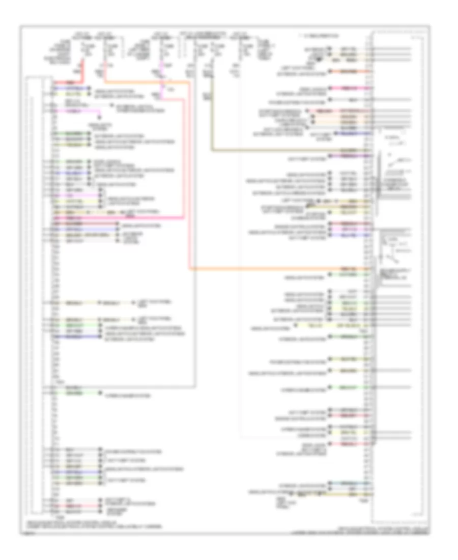
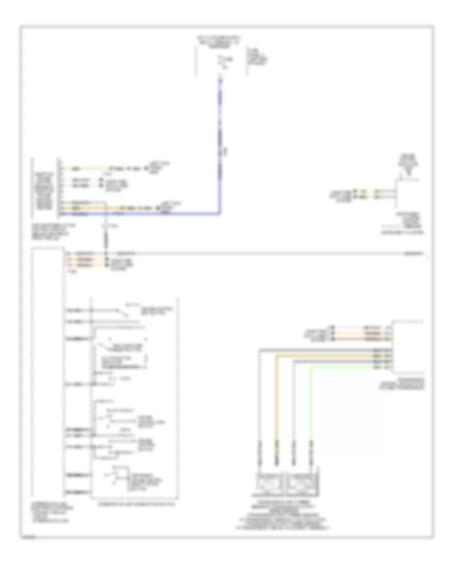
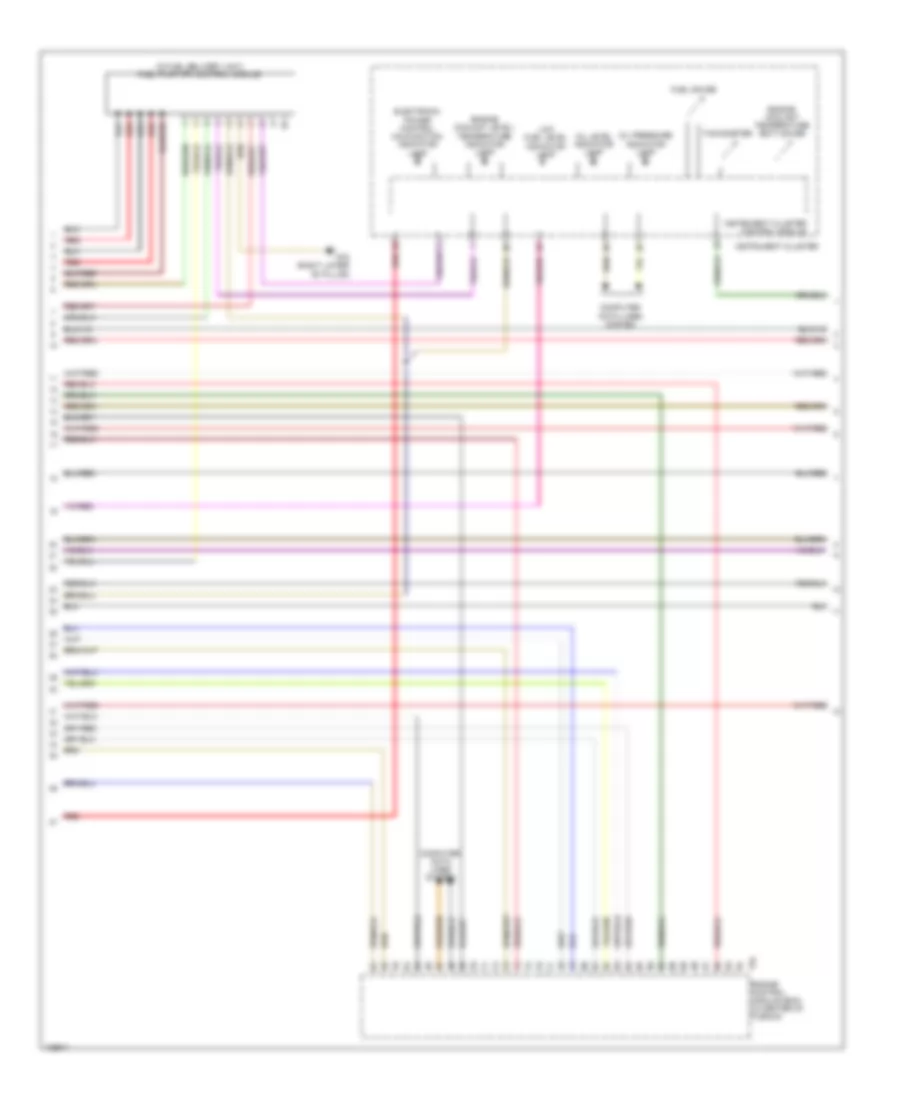
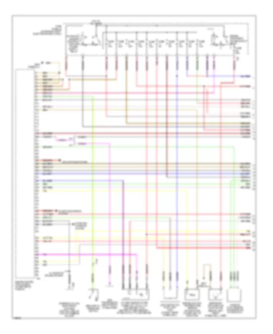
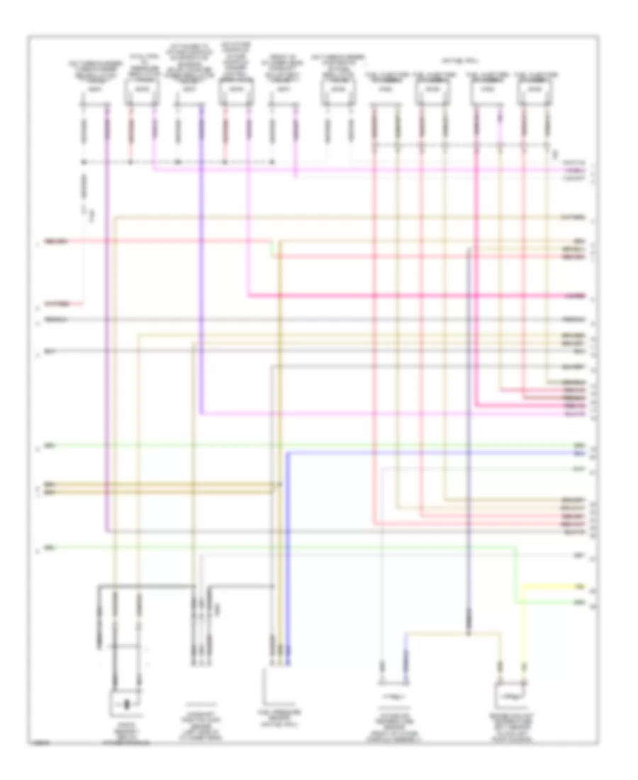
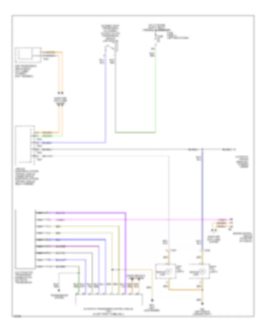
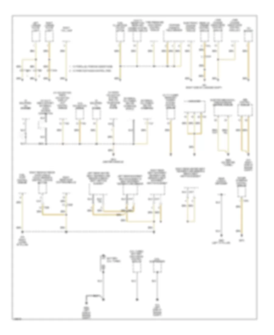
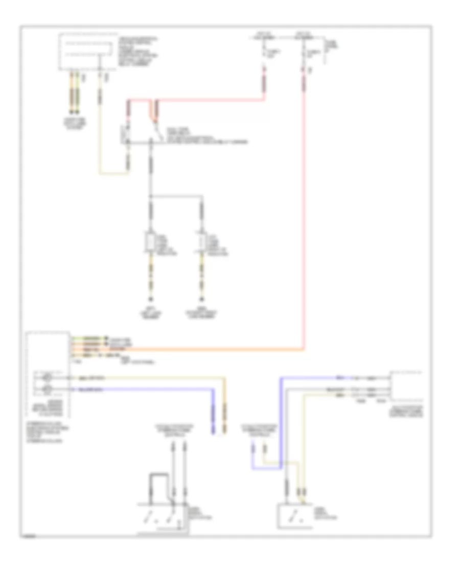
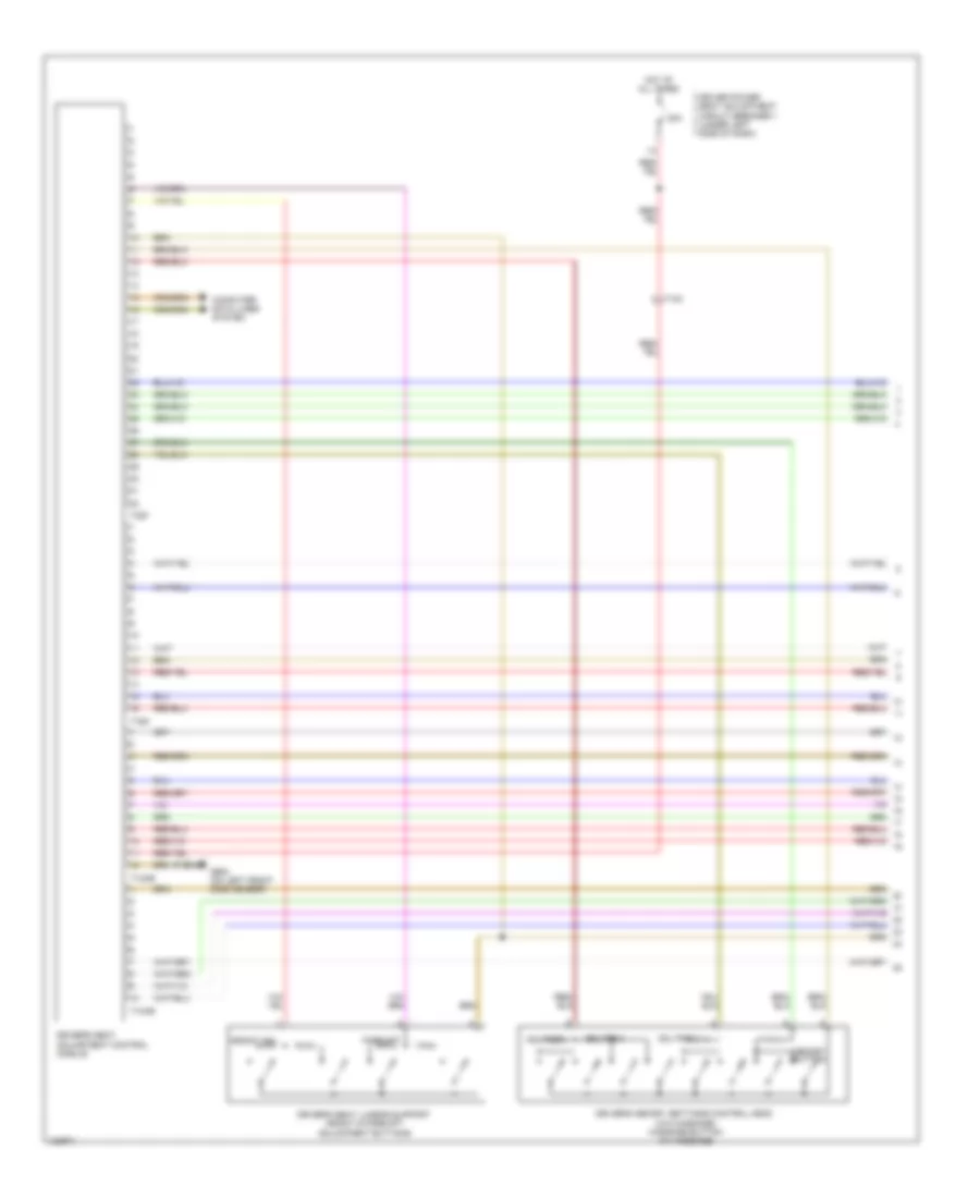
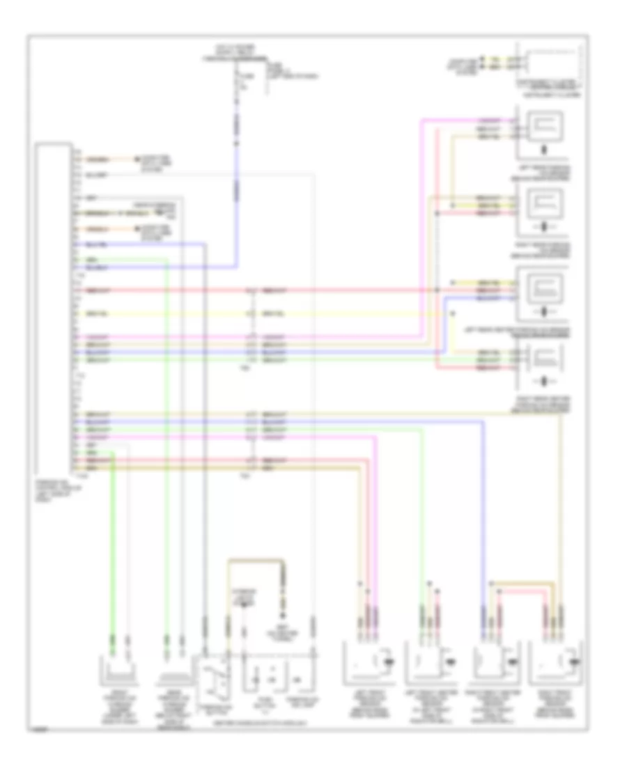
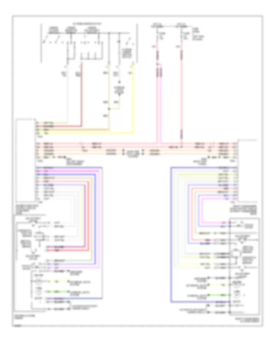
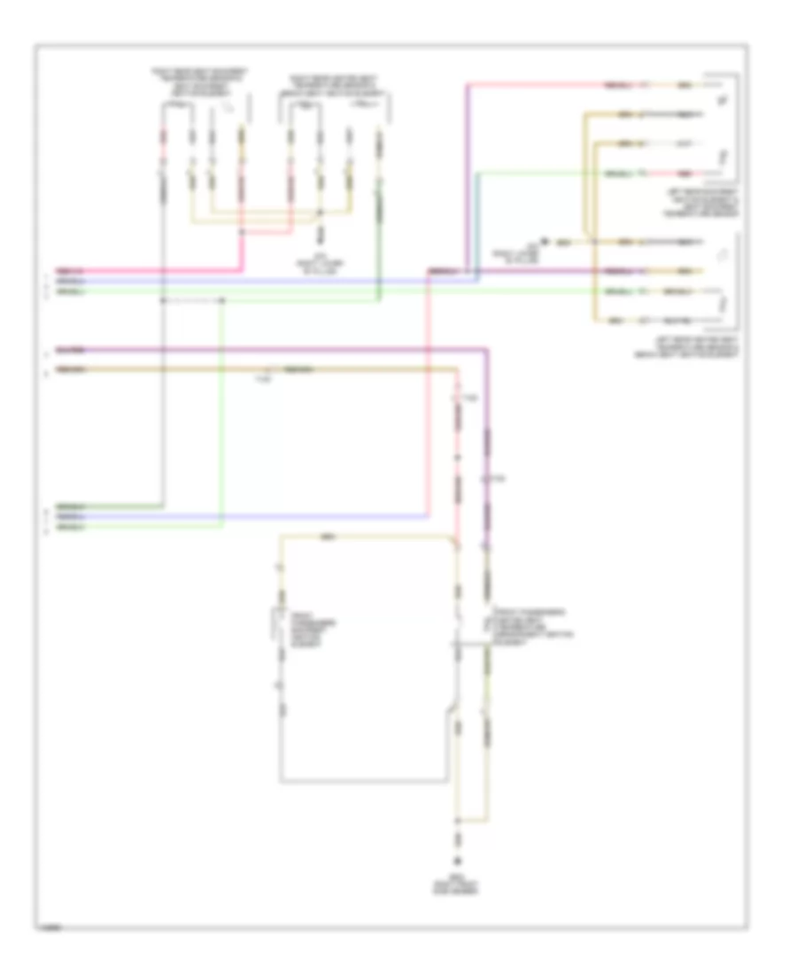
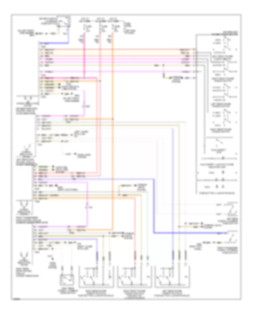
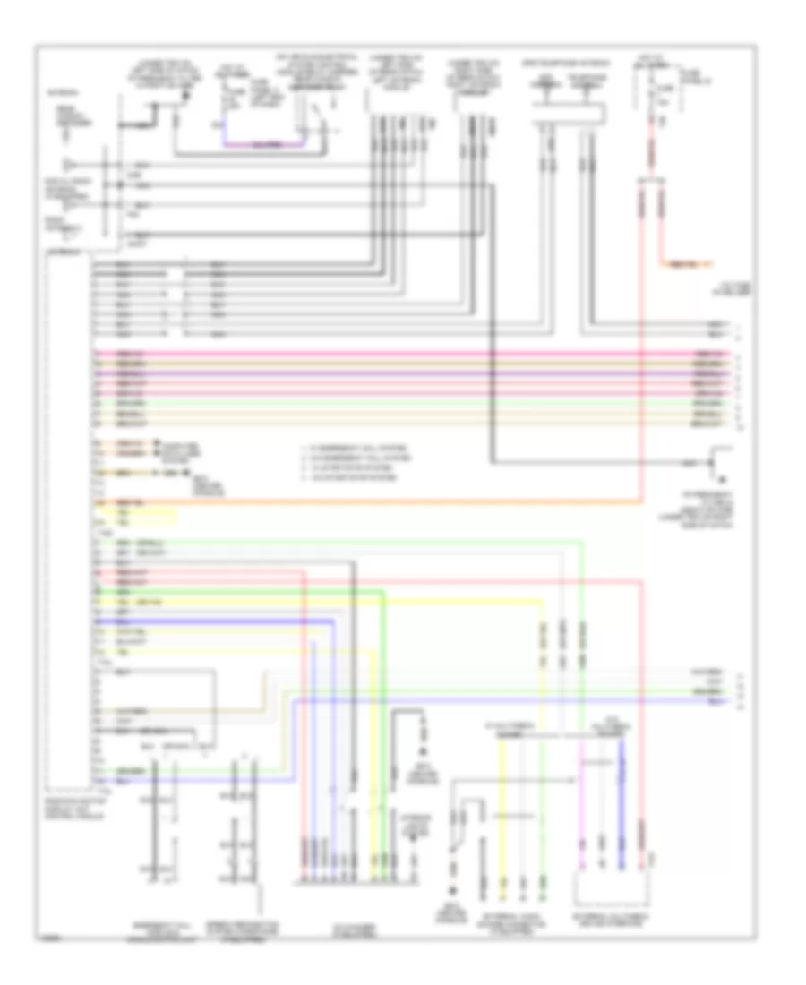
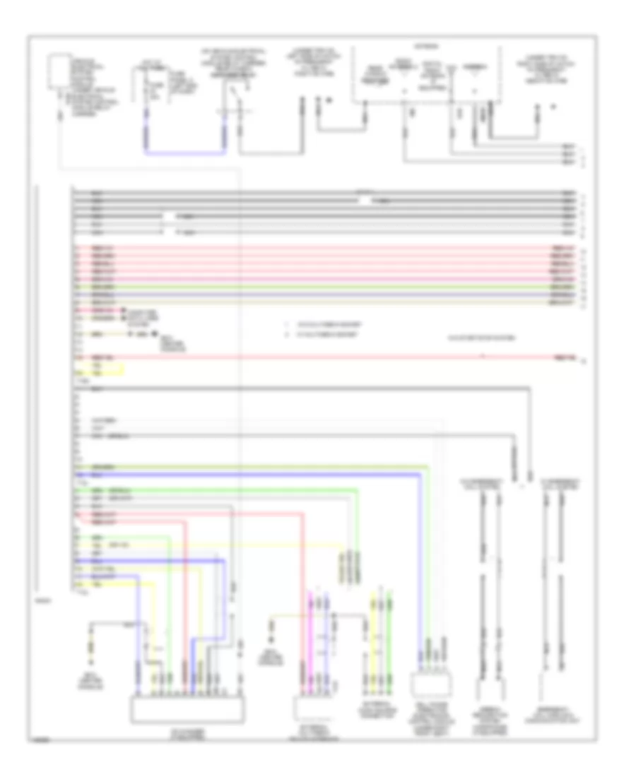
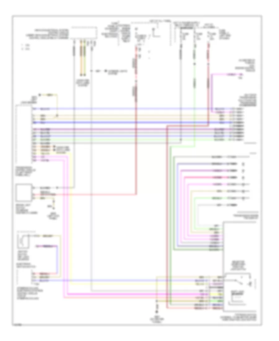
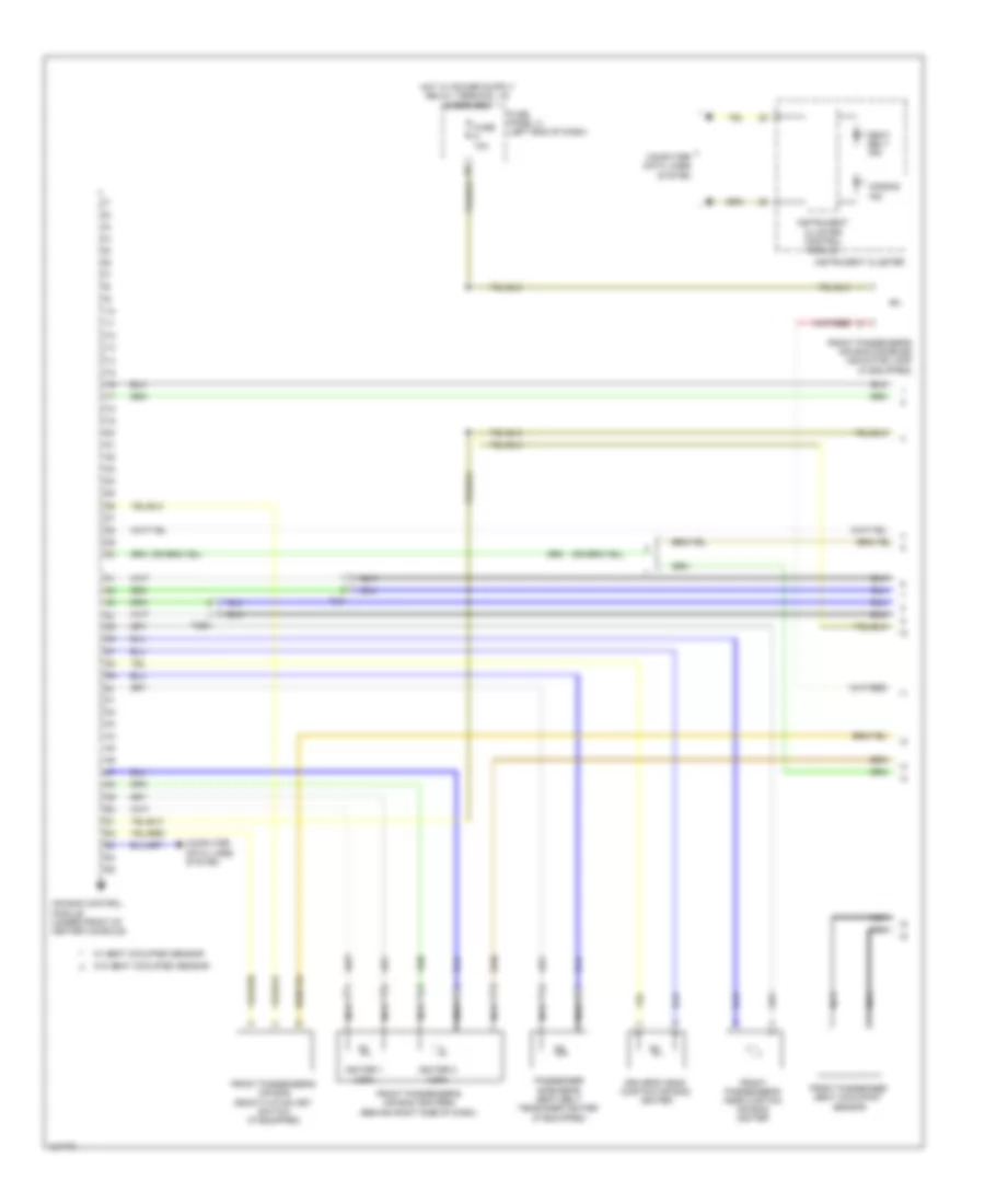
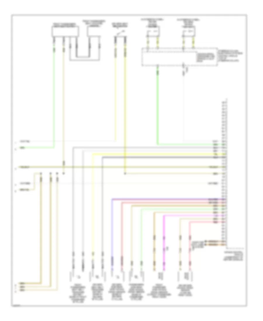
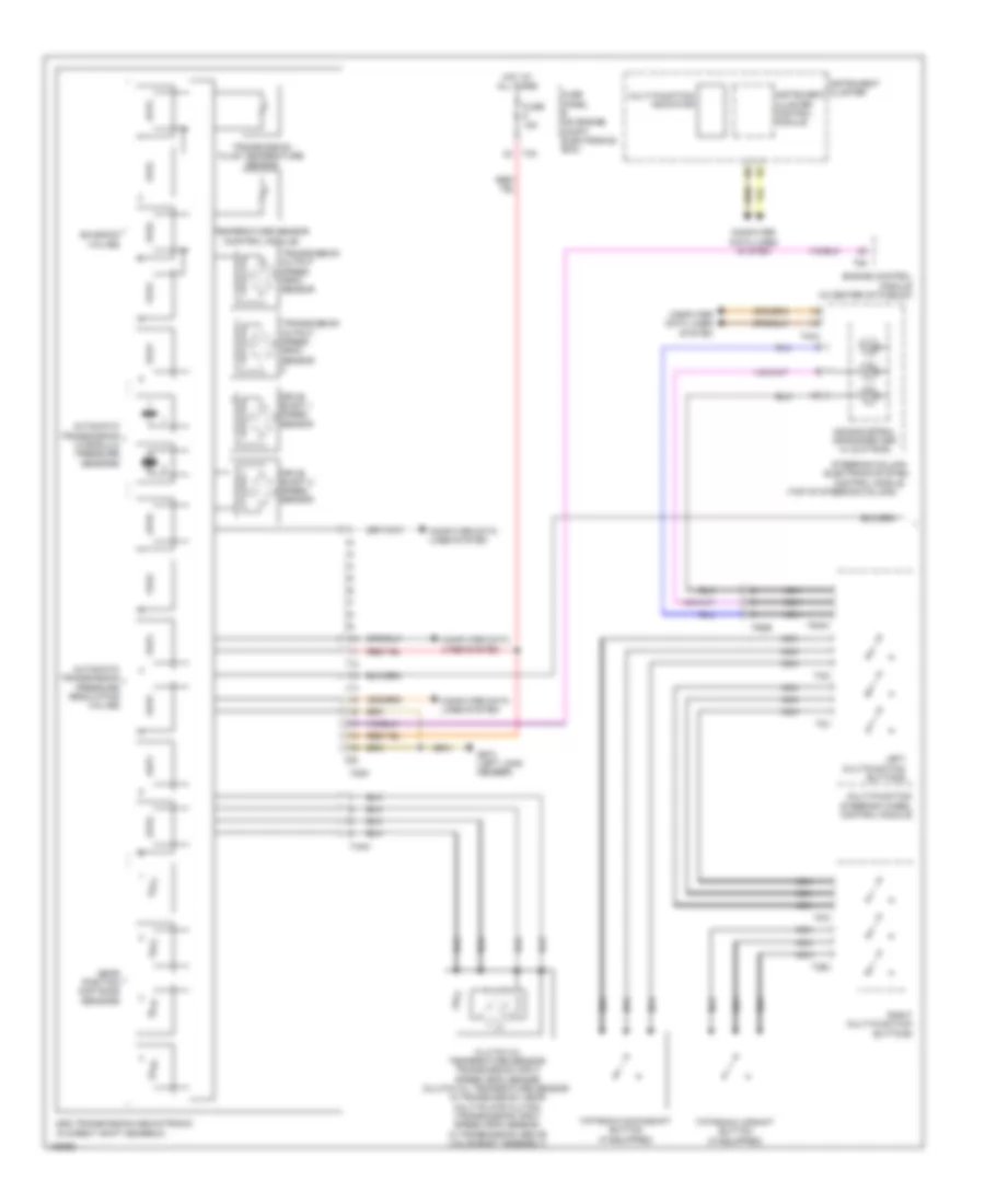
AIR CONDITIONING
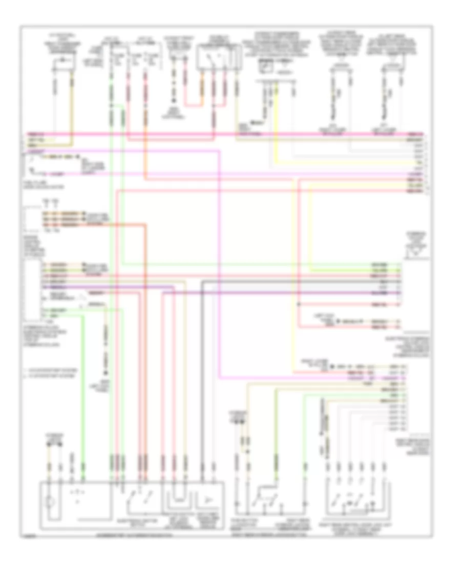
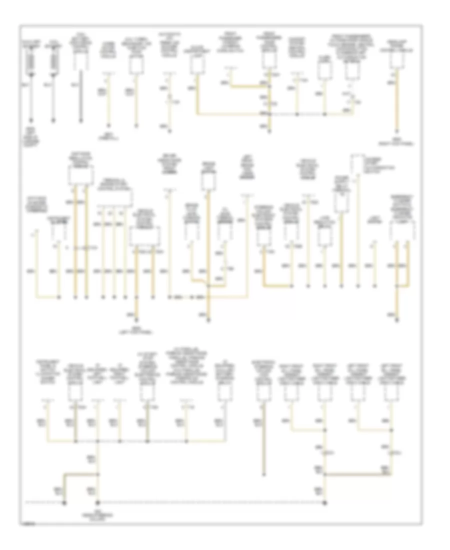
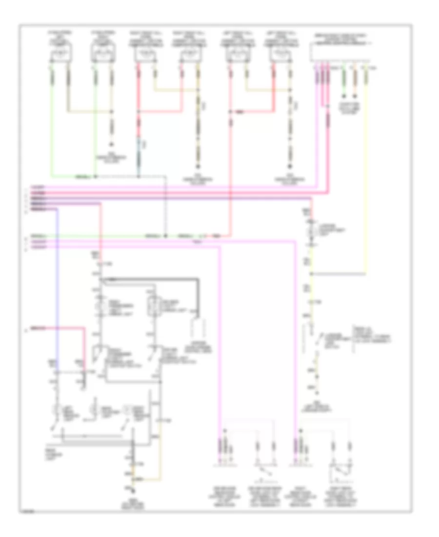
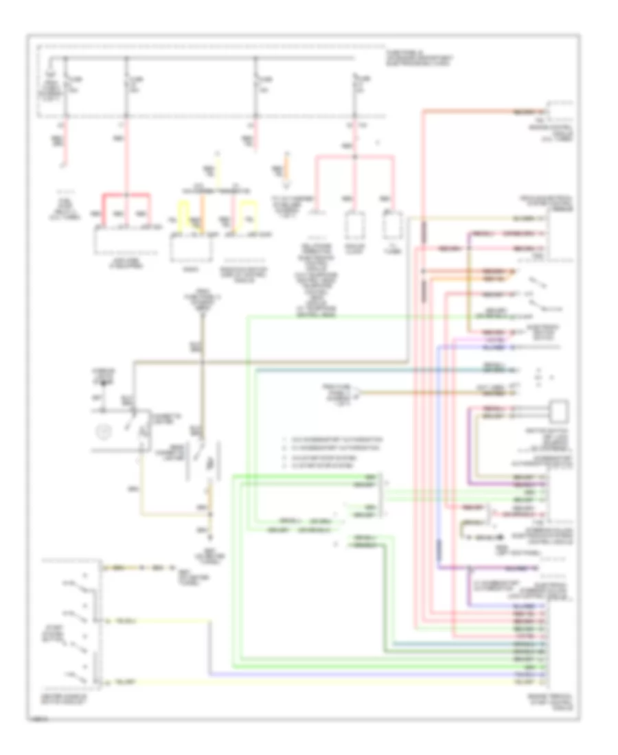
Automatic A/C Wiring Diagram (1 of 3) for Volkswagen CC R-Line 2014
 https://portal-diagnostov.com/license.html
Automotive Electricians Portal FZCO
Automotive Electricians Portal FZCO
https://portal-diagnostov.com/license.html
https://portal-diagnostov.com/license.html
Automotive Electricians Portal FZCO
Automotive Electricians Portal FZCO
List of elements for Automatic A/C Wiring Diagram (1 of 3) for Volkswagen CC R-Line 2014:
- 15a
- 38a
- Air quality sensor
- Climatronic control module (integral to climatronic control head)
- Computer data lines system
- Defroster door motor position sensor (top left side of hvac unit)
- Fuse 10a
- Fuse 40a
- Fuse panel c (left end of dash)
- G687 (on center tunnel)
- Hot at all times
- Indirect ventilation door motor position sensor (if equipped) (top center of of hvac unit)
- Left footwell vent temperature sensor (left side of hvac unit)
- Left temperature door potentiometer/ actuator & motor
- Right footwell vent temperature sensor (front center of hvac unit)
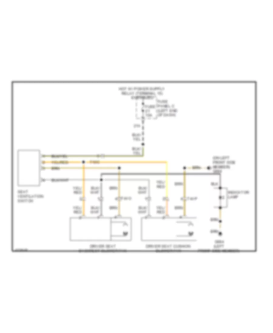
- Seats system
- T10f
- T16h
- T16i
- T20c
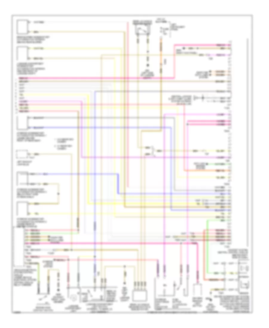
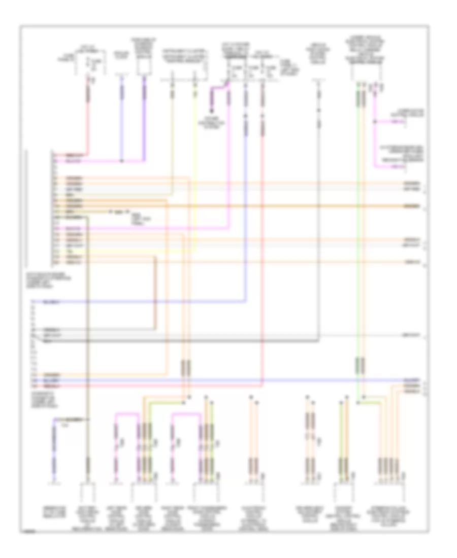
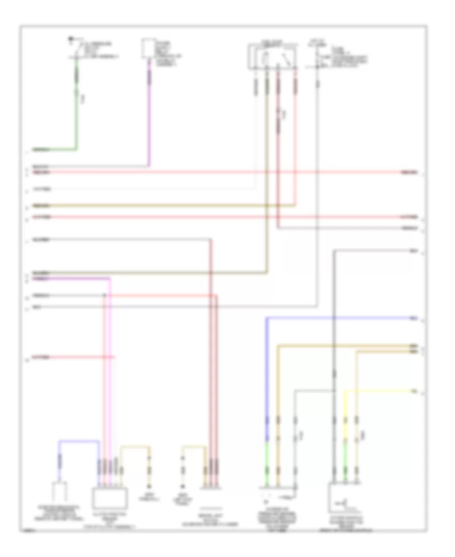
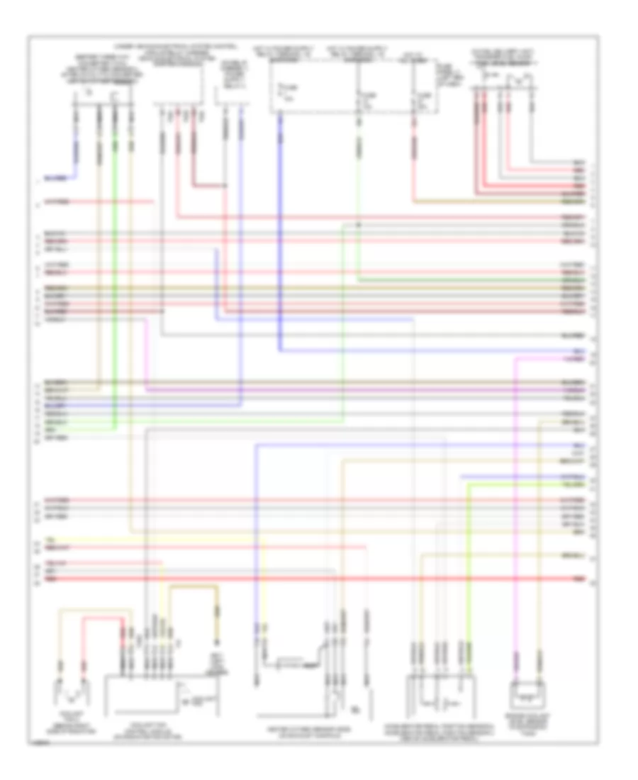
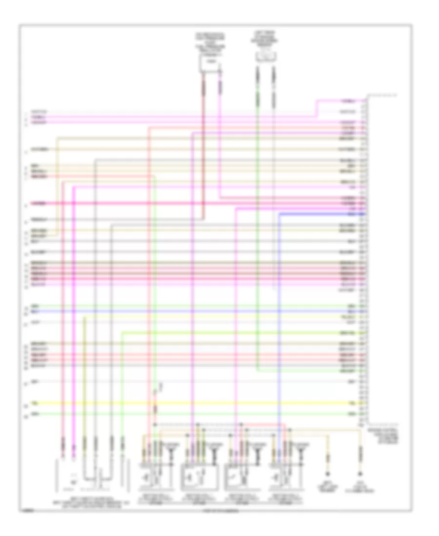
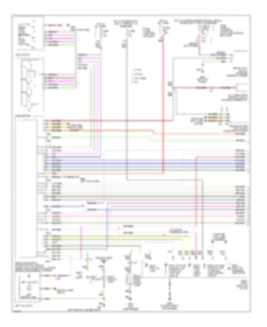
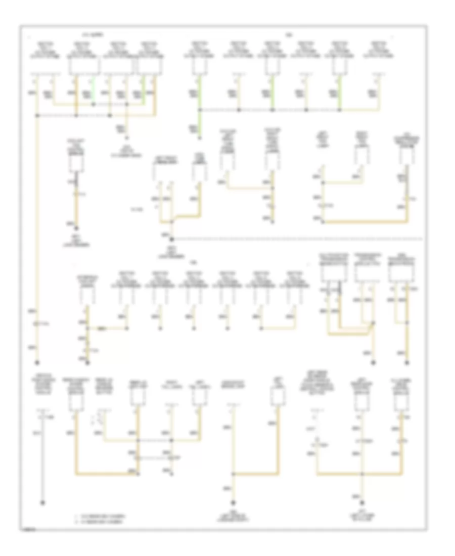
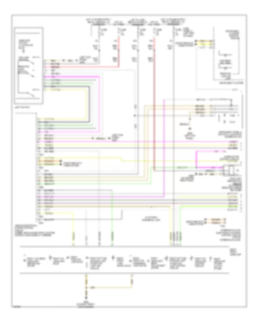
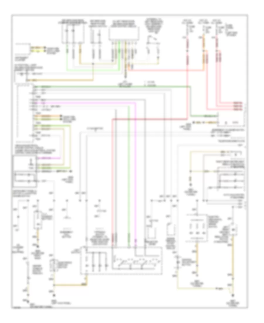
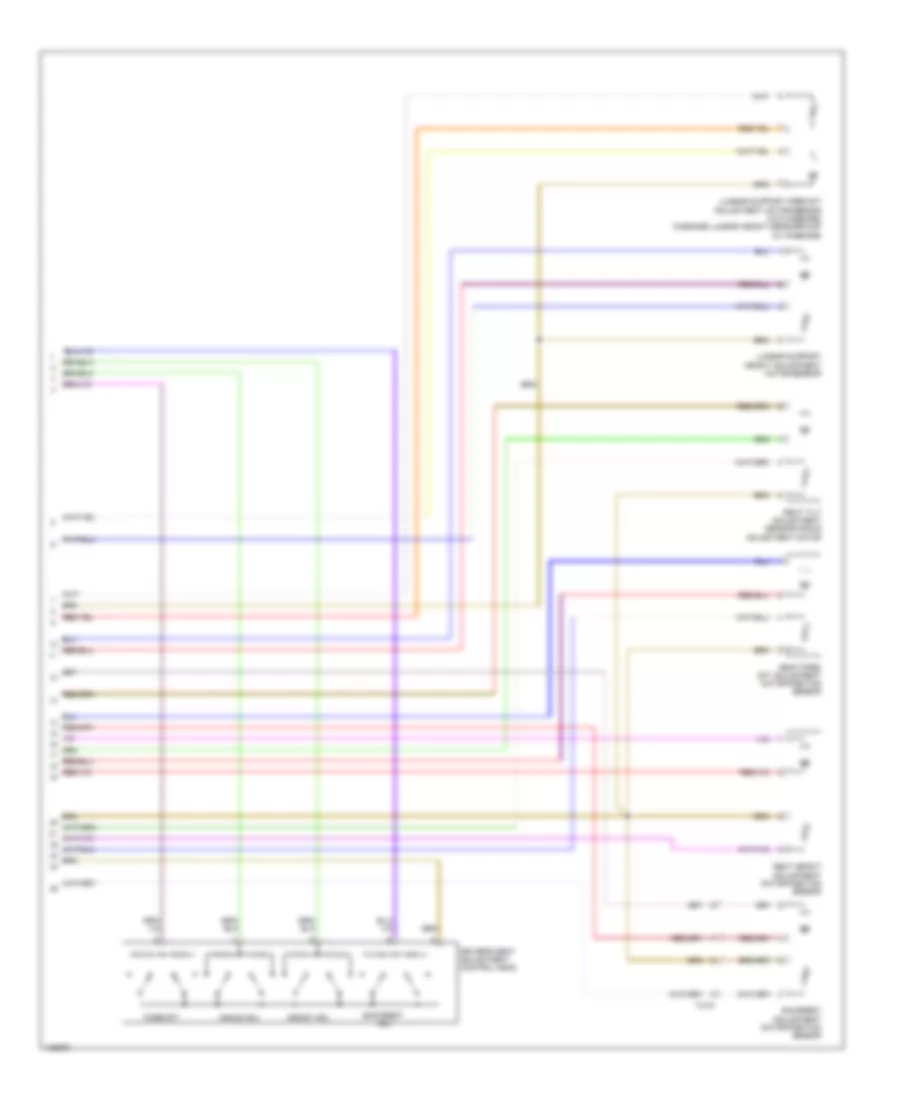
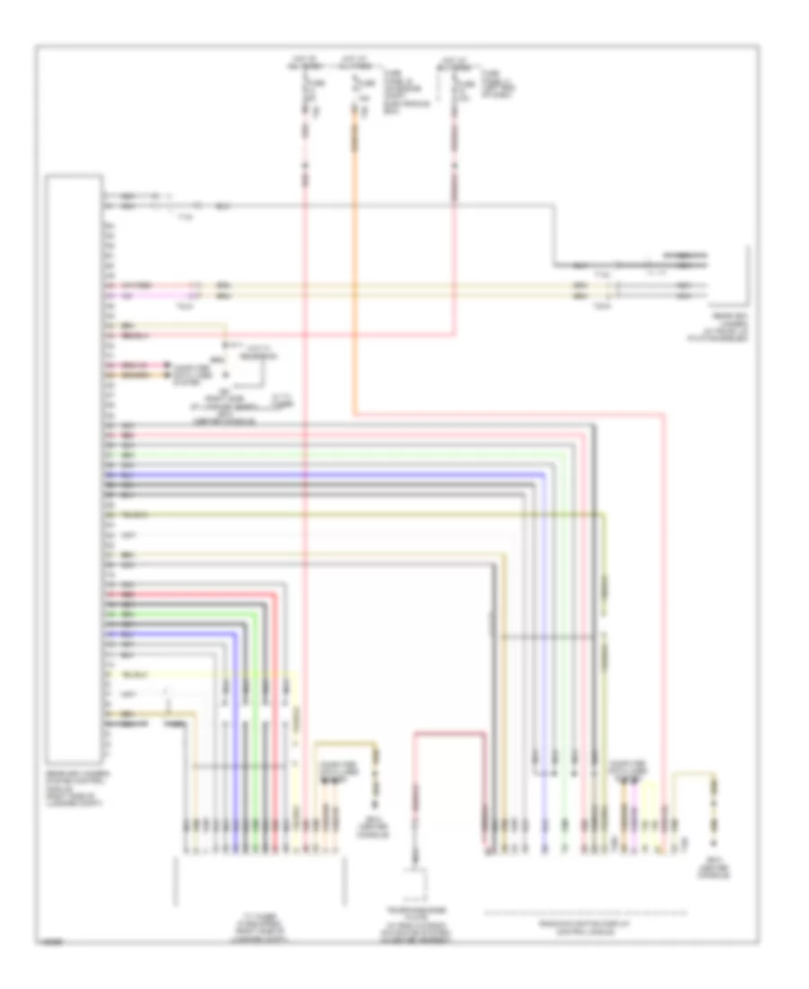
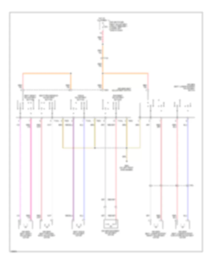
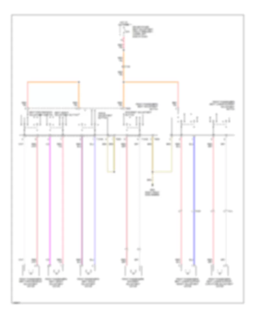
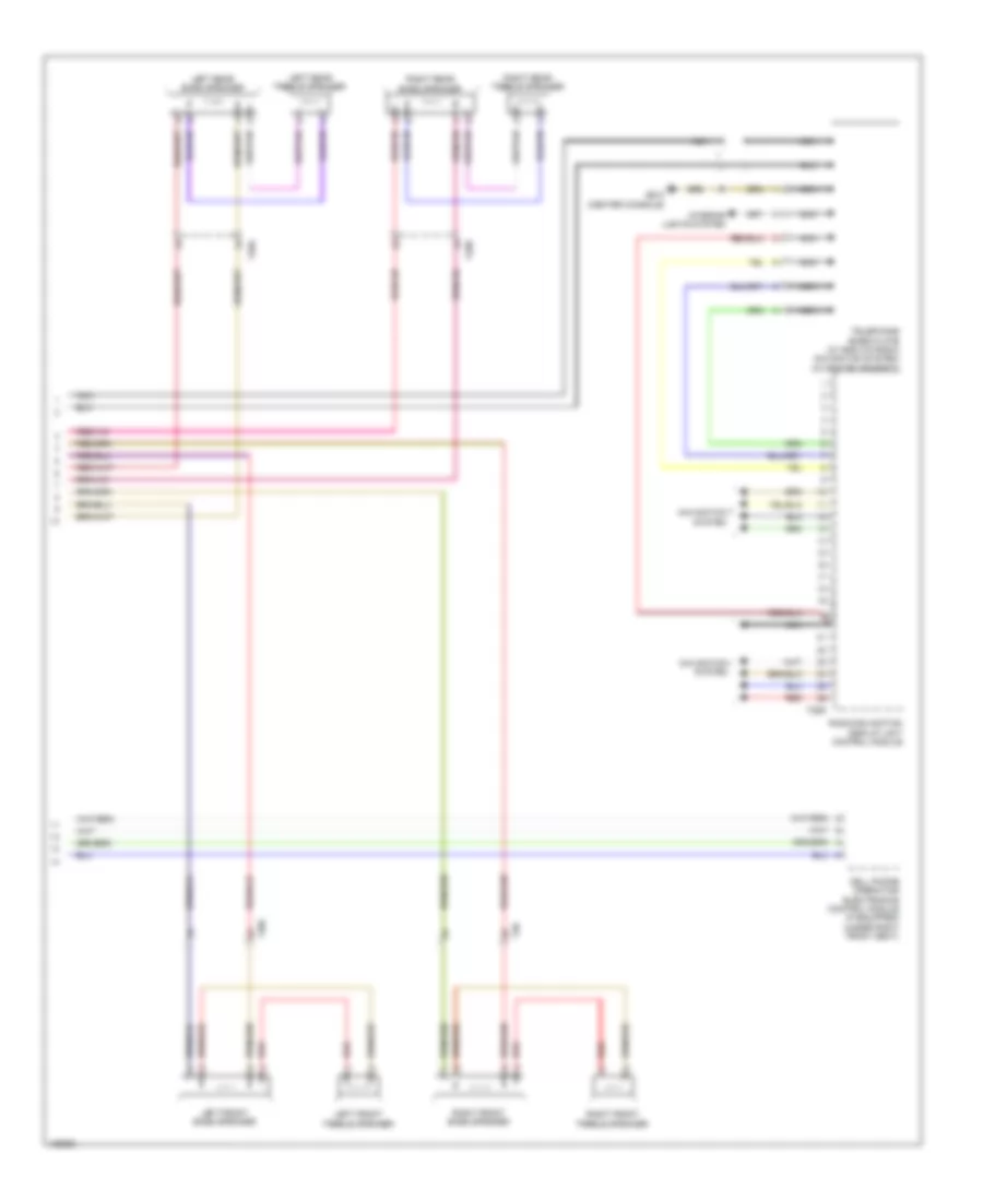
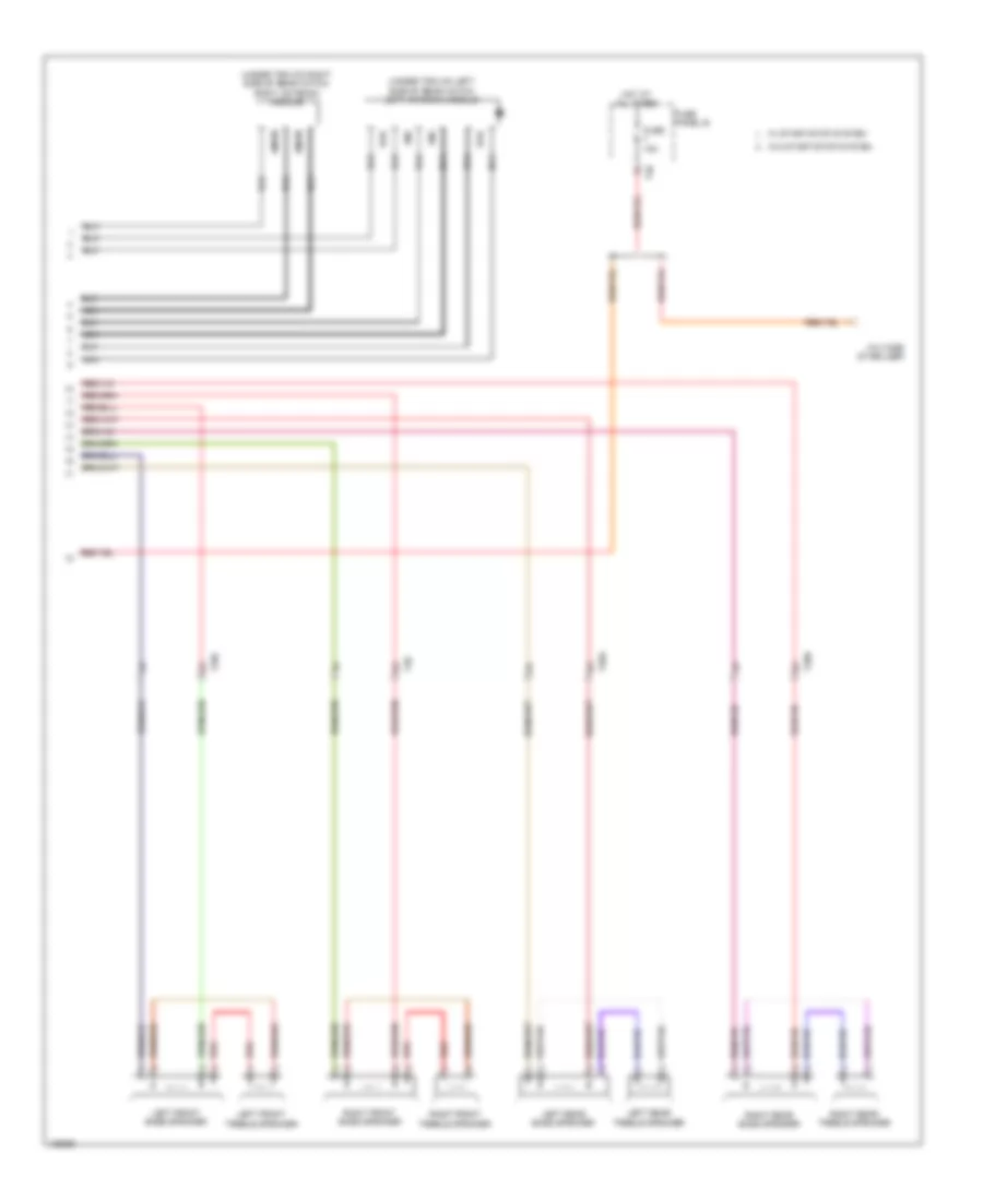
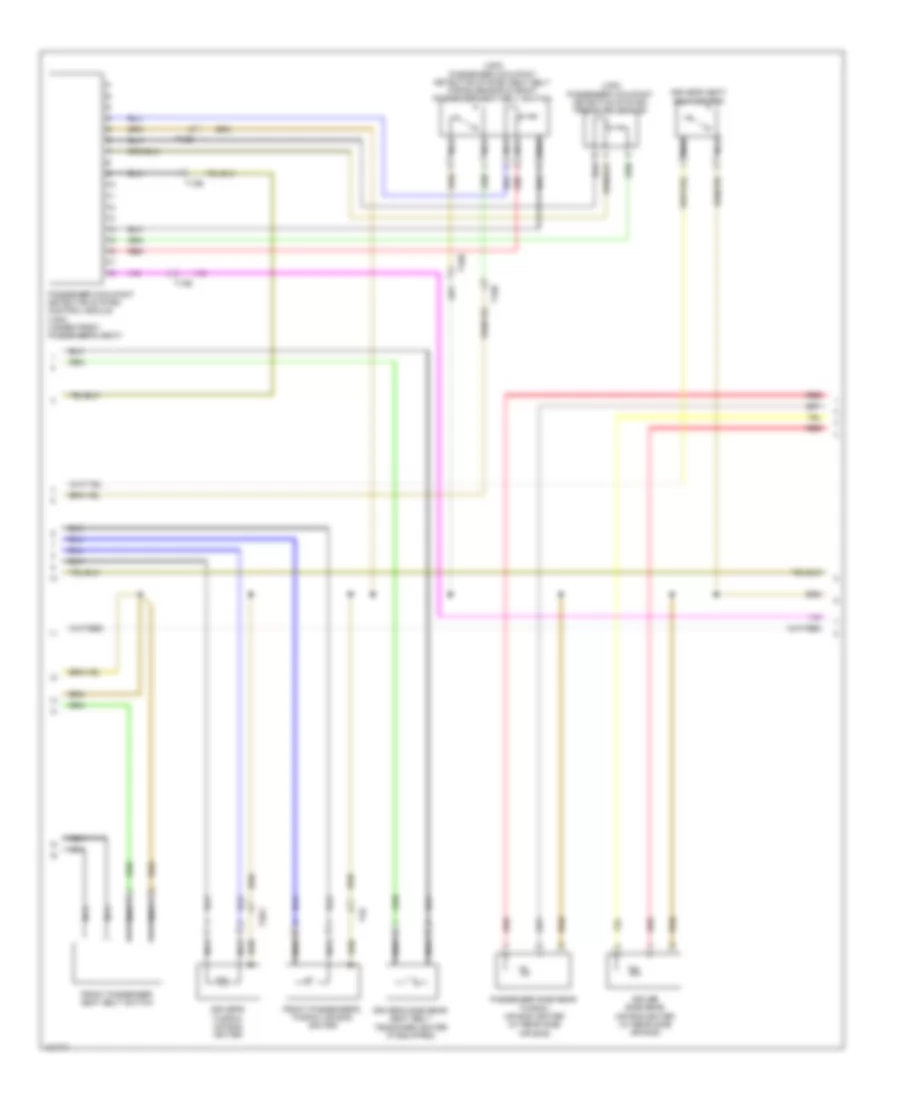
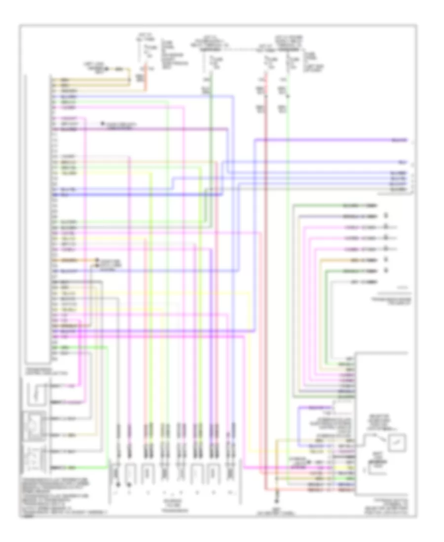
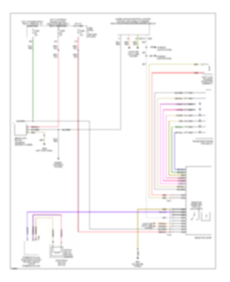
Automatic A/C Wiring Diagram (2 of 3) for Volkswagen CC R-Line 2014
List of elements for Automatic A/C Wiring Diagram (2 of 3) for Volkswagen CC R-Line 2014:
- (not used)
- 2.0l turbo
- 3.6l
- After-run coolant pump (3.6l) (lower left rear of engine)
- Coolant circulation pump relay (3.6l)
- Evaporator temperature sensor (front center of hvac unit)
- Fresh air blower (under right side of hvac unit)
- Fresh air blower control module (on fresh air blower motor)
- Fresh air/recirculating air/back pressure door motor position sensor (on fresh air recirculating door motor)
- Front air distribution door motor position sensor (top left side of hvac unit)
- Fuse 10a
- Fuse panel b (on engine compt electronics box (high))
- G638 (right kick panel)
- G673 (on left long member)
- Hot at all times
- Nca
- Right temperature door motor & potentiometer/ actuator (front center of hvac unit)
- T10f
- T14a
- T26a
- T2gc
- T40
- T6be
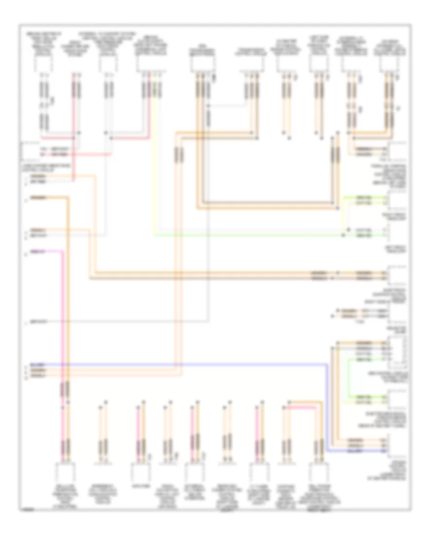
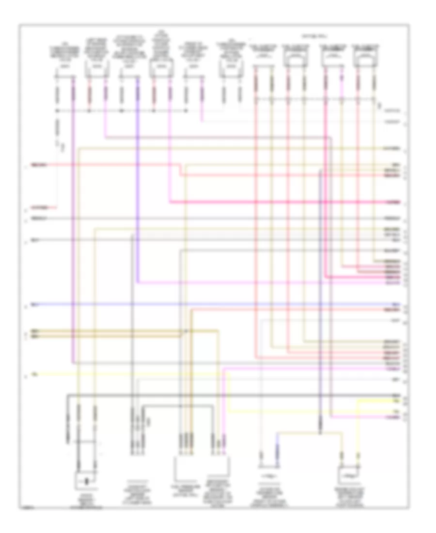
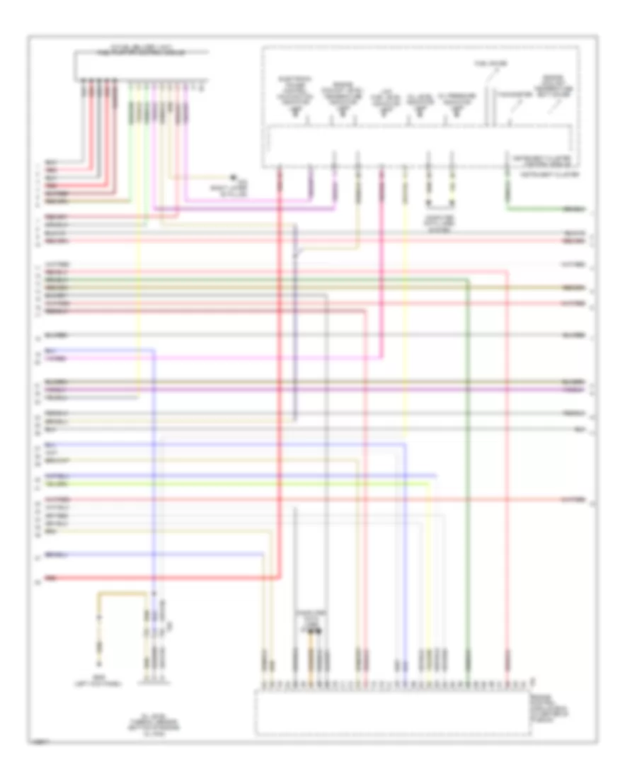
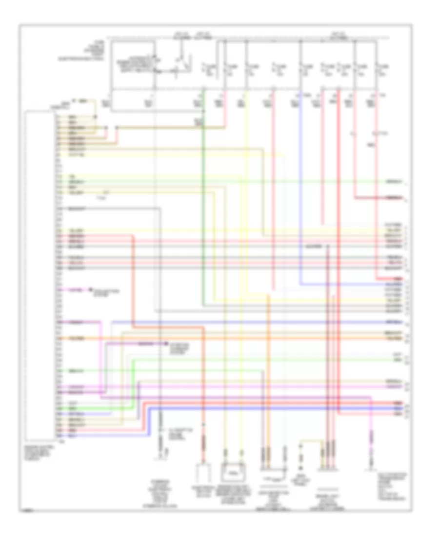
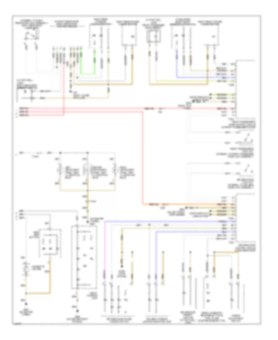
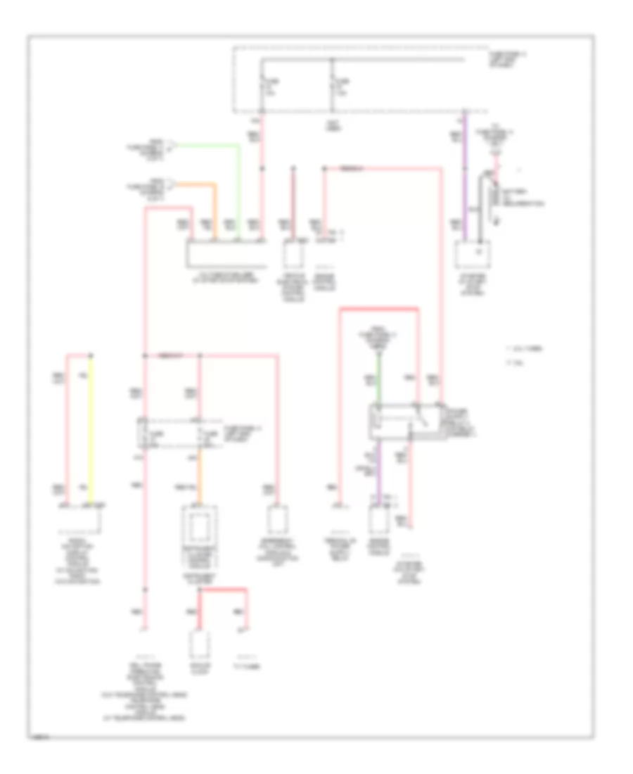
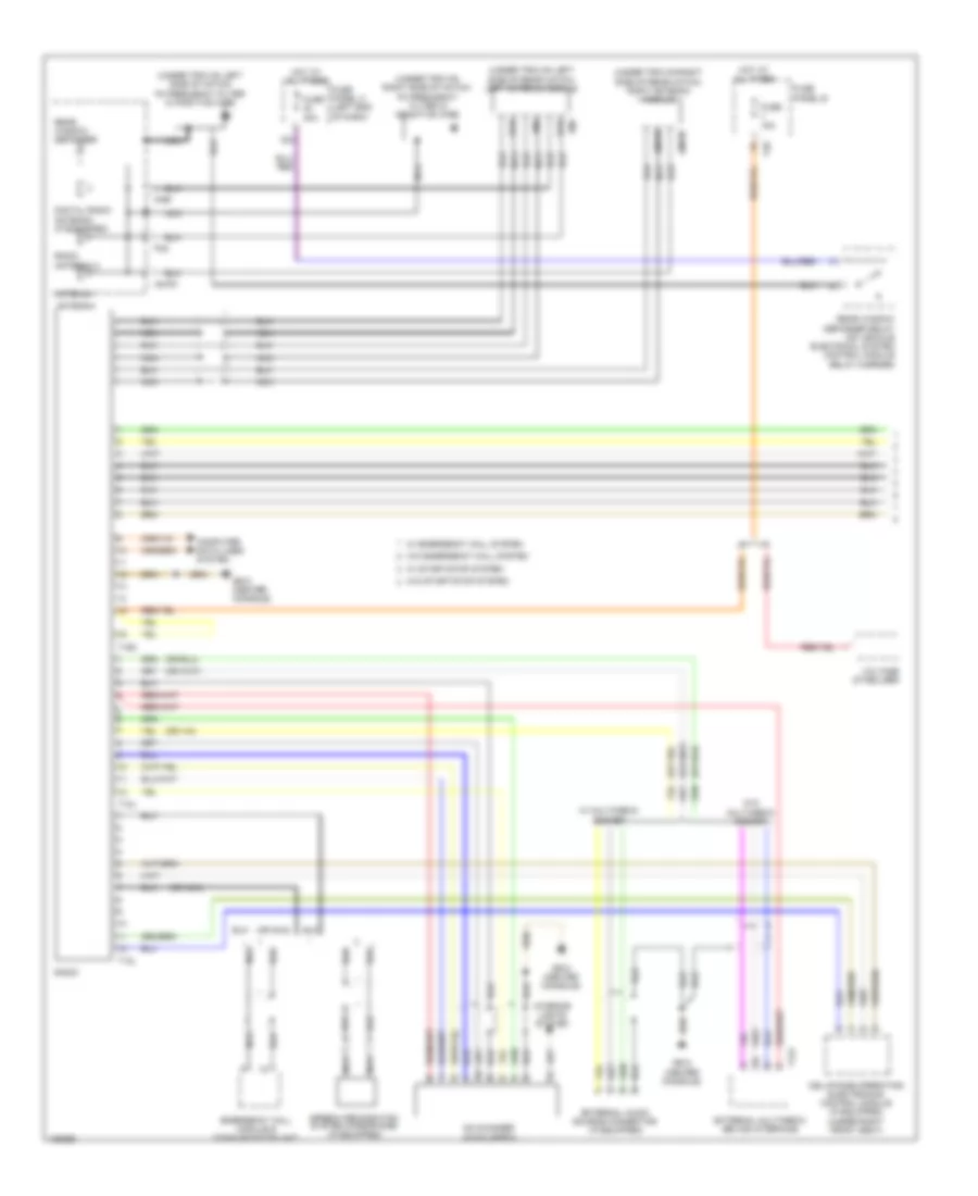
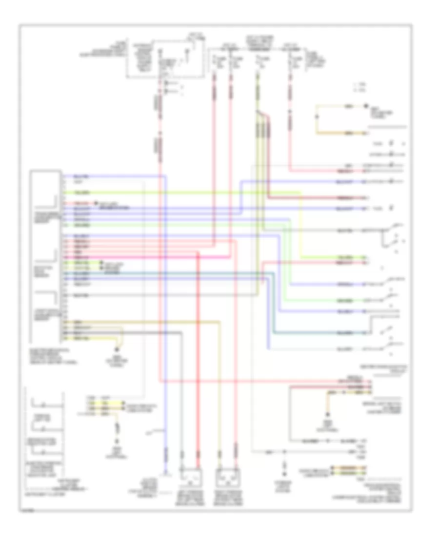
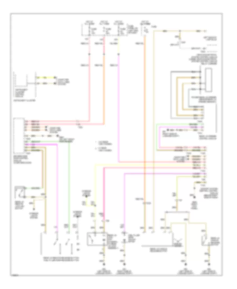
Automatic A/C Wiring Diagram (3 of 3) for Volkswagen CC R-Line 2014
List of elements for Automatic A/C Wiring Diagram (3 of 3) for Volkswagen CC R-Line 2014:
- 2.0l turbo
- 3.6l
- A/c compressor regulating valve (on a/c compressor)
- After-run coolant pump (2.0l turbo) (lower left rear of engine)
- Computer data lines system
- Coolant circulation pump relay (2.0l turbo) (on relay carrier 1)
- Coolant fan
- Coolant fan 2 (behind right side of radiator)
- Coolant fan control (fc) module (on radiator fan motor)
- Engine control module (ecm) (in center of plenum)
- Engine coolant level (ecl) sensor
- Engine coolant level/ temperature indicator lamp
- Engine coolant temperature (ect) gauge
- Engine coolant temperature (ect) sensor (2.0l turbo: in coolant pump housing) (3.6l: left rear of engine)
- Engine coolant temperature (ect) sensor (on radiator) (lower left of radiator)
- Fuse 50a
- Fuse panel a (on engine compt electronics box (high & low)
- G645 (firewall)
- G671 (left long member)
- G673 (left long member)
- G685 (on right front long member)
- High pressure sensor (right front of engine compt)
- Hot at all times
- Instrument cluster
- Instrument cluster control module
- Left vent temperature sensor (near left vent)
- Nca
- Red
- Right vent temperature sensor (near right vent)
- Sunlight photo sensor (under top center of dash)
- T2be
- T2ck
- T4a
- T4i
- T60
- T94
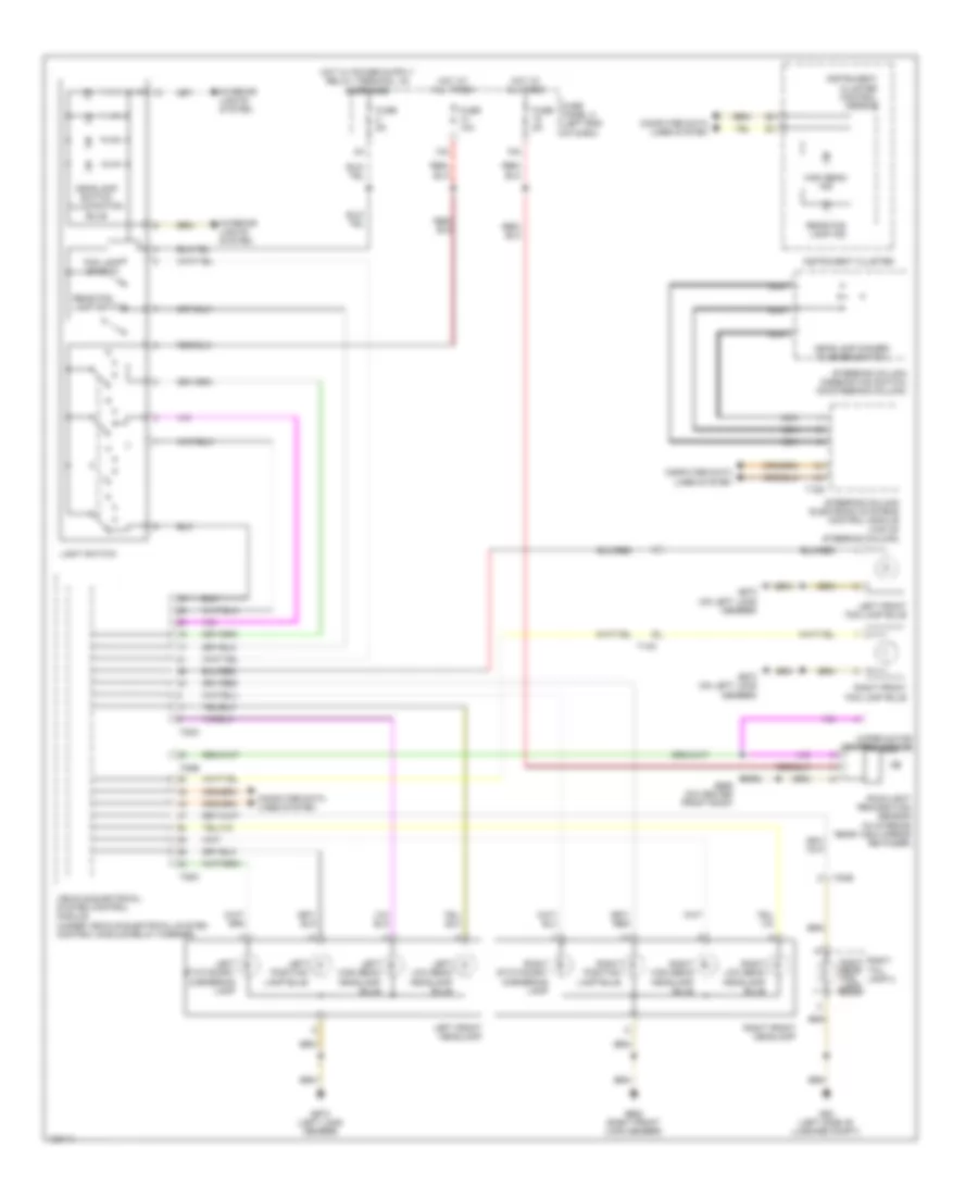
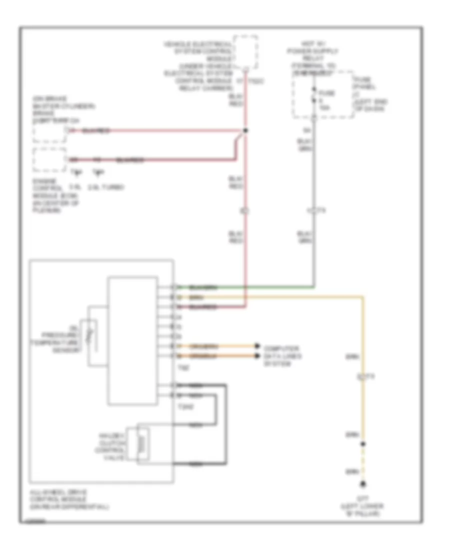
ANTI-LOCK BRAKES
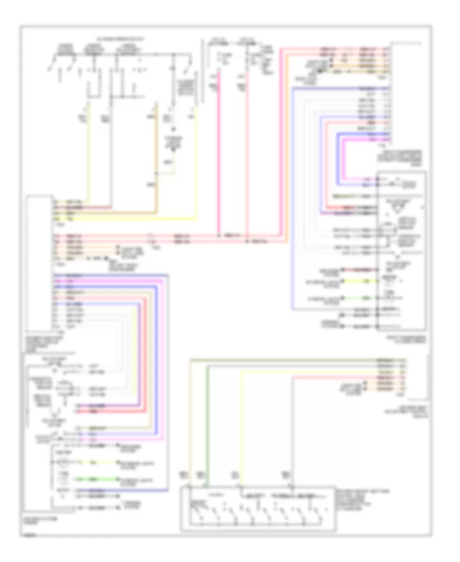
Anti-lock Brakes Wiring Diagram for Volkswagen CC R-Line 2014
List of elements for Anti-lock Brakes Wiring Diagram for Volkswagen CC R-Line 2014:
- (right side of engine compt) g13
- 13a
- 2.0l turbo
- 3.6l
- Abs control module (on right side of firewall)
- Abs ind lamp
- Abs return flow pump
- Asr/esp button
- Asr/esp ind lamp
- Brake light switch (on brake master cylinder)
- Brake system ind lamp
- Center console switch module 1
- Cluster
- Computer data lines system
- Control module
- Electro-mechanical parking brake control module (rear of center tunnel)
- Fuse 20 fuse 8 5a 10a
- Fuse 20a
- Fuse 30a
- Fuse 40a
- Fuse 5a
- Fuse panel a (on engine compt electronics box)
- Fuse panel b
- Fuse panel c (left end of dash)
- G13 (right side of engine compt)
- G639 (left kick panel)
- G687 (on center tunnel)
- Hot at all times
- Instrument
- Instrument cluster
- Interior lights system
- Left front abs inlet valve
- Left front abs outlet valve
- Left front abs wheel speed sensor (on left front wheel bearing housing)
- Left front brake pad wear sensor (on left front brake caliper assembly)
- Left front edl outlet valve
- Left rear abs inlet valve
- Left rear abs outlet valve
- Left rear abs wheel speed sensor (on left rear wheel bearing assembly)
- Push button illumination bulb
- Red
- Reservoir)
- Right front abs inlet valve
- Right front abs outlet valve
- Right front abs wheel speed sensor (on right front wheel bearing housing)
- Right front edl switch-over valve
- Right rear abs inlet valve
- Right rear abs outlet valve
- Right rear abs wheel speed sensor (on right rear wheel bearing assembly)
- Steering angle sensor
- Steering column electronics control module (top of steering column)
- T16o
- T40
- T52c
- Vacuum sensor (if equipped)
- Vehicle electrical system control module (under vehicle electrical system control module relay carrier)
- W/ electronics box high
- W/ electronics box low
ANTI-THEFT
Access/Start Wiring Diagram for Volkswagen CC R-Line 2014
List of elements for Access/Start Wiring Diagram for Volkswagen CC R-Line 2014:
- (not used)
- 15a
- 16a
- 2.0l
- 3.6l
- Access/start authorization switch
- Anti-theft immobilizer reading module
- Center console switch module 1
- Comfort system central control module (behind right side of dash)
- Computer data lines system
- Electronic ignition switch
- Electronic steering column lock control module (near base of steering column)
- Engine control module (in center of plenum)
- Engine terminal start control module
- Fuse 10a
- Fuse 5a
- Fuse panel c (left end of dash)
- G639 (left kick panel)
- G687 (on center tunnel)
- Hot at all times
- Ignition switch key lock solenoid (w/ tiptronic)
- Interior lights system
- Push button illumination
- Start system button
- Steering column electronic systems control module (top of steering column)
- T16o
- T18a
- T52b
- T52c
- T94
- Vehicle electrical system control module (under vehicle electrical system control module relay carrier)
Forced Entry Wiring Diagram (1 of 3) for Volkswagen CC R-Line 2014
List of elements for Forced Entry Wiring Diagram (1 of 3) for Volkswagen CC R-Line 2014:
- (if equipped)
- (integral to driver's door lock assembly) driver's central door lock unit
- 12a
- 28a
- Bulb
- Central locking safe indicator lamp
- Child safety lock activate indicator lamp
- Child safety lock button
- Computer data lines system
- Driver door ambient lighting bulb (w/ footwell lamp)
- Driver door control module (in driver's door)
- Driver interior locking button
- Driver interior locking indicator lamp
- Driver's side power window switch
- Driver's side rear interior locking button
- Front passenger door control module (in front passenger's door)
- Front passenger interior locking indicator lamp
- Front passenger's central door lock unit (integral to front passenger's door lock assembly)
- Front passenger's interior locking button
- Fuse 10a
- Fuse 30a
- Fuse panel c (left end of dash)
- G638 (right kick panel)
- G684 (on left front side member)
- G77 (left lower "b" pillar)
- Hot at all times
- Illumination push button
- Interior lights system
- Left rear central door lock unit (integral to left rear door lock assembly)
- Left rear door control module (in left rear door)
- Left rear interior locking indicator lamp
- Power windows & mirrors systems
- Power windows system
- Push button illumination bulb
- Rear lid remote & fuel filler door release button
- Rear lid remote lock key switch
- T20g
- T20h
- T28
- T28a
- T28c
- T32a
- T32b
Forced Entry Wiring Diagram (2 of 3) for Volkswagen CC R-Line 2014
List of elements for Forced Entry Wiring Diagram (2 of 3) for Volkswagen CC R-Line 2014:
- (in front passenger's outside door handle) front passenger's outside door handle touch sensor, central locking button & access/ start authorization antenna
- (in left rear outside door handle) left rear outside door handle touch sensor & central locking button
- (in right front wheelwell) alarm horn
- (in right rear outside door handle) right rear outside door handle touch sensor & central locking button
- (left kick panel) g639
- (not used)
- (on relay carrier 2) alarm horn relay
- (right lower "b" pillar) g78
- (w/ footwell lamp) front passenger door ambient lighting bulb
- 14a
- 16a
- 2.0l
- 3.6l
- 35a
- Access/start authorization switch
- Antenna
- Anti-theft immobilizer reading module
- Computer data lines system
- Electronic ignition switch
- Electronic steering column lock control module (near base of steering column)
- Engine control module (in center of plenum)
- Fuel filler door unlock motor
- Fuse 10a
- Fuse 30a
- Fuse panel c (left end of dash)
- G51 (right side of luggage compt)
- G638 (right kick panel)
- G639 (left kick panel)
- G77 (left lower "b" pillar)
- G78 (right lower "b" pillar)
- Hot at all times
- Ignition switch key lock solenoid (w/ tiptronic)
- Interior lights system
- Push button illumination bulb
- Right rear central door lock unit (integral to right rear door lock assembly)
- Right rear door control module (in right rear door)
- Right rear interior locking button
- Right rear interior locking indicator lamp
- Sensor
- Steering column electronic systems control module (top of steering column)
- Steering column lock actuator
- System power windows
- T16o
- T28
- T28a
- T28b
- T94
- W/ stop/start system
- W/o stop/start system
Forced Entry Wiring Diagram (3 of 3) for Volkswagen CC R-Line 2014
List of elements for Forced Entry Wiring Diagram (3 of 3) for Volkswagen CC R-Line 2014:
- Antenna
- Anti-lock brakes system
- Central locking & anti-theft alarm system antenna (in "a" pillar)
- Comfort system central control module (behind right side of dash)
- Computer data lines system
- Driver access/start system antenna, exterior door handle central locking button & exterior door handle touch sensor (in driver's outside door handle)
- Driver's reading light button
- Engine hood contact switch
- Fuse 15a
- G50 (left side of luggage compt)
- G638 (right kick panel)
- G684 (on left front side member)
- G685 (on right front long member)
- Hot at all times
- Interior access/start authorization antenna 1 (under center, front of rear seat)
- Interior access/start authorization antenna 2 (under rear of center console)
- Interior access/start authorization antenna 3 (below right side of rear shelf)
- Interior lights system
- Interior monitoring deactivation switch
- Interior monitoring off indicator lamp
- Left backup lamp bulb
- Left instrument panel
- Luggage compartment access/start authorization antenna (center front of luggage compt)
- Luggage compartment light
- Luggage compartment light switch (integral to rear lid lock assembly)
- Nca
- Push button illumination bulb
- Rear bumper access/start authorization antenna (behind rear bumper)
- Rear lid central locking system motor
- Rear lid handle release switch
- Rear lid handle release switch & emblem motor
- Rear lid lock unit
- Sensor
- T12kf
- T18a
- T18c
- T28
- T28a
- T28b
- T28c
- T2e
- T2f
- T2ks
- T4uy
- T52a
- T52b
- T52c
- T6an
- T6ao
- T8r
- Vehicle electrical system control module (under vehicle electrical system control module relay carrier)
- W/ rearview camera
- W/o rearview camera
BODY CONTROL MODULES
Steering Column Electronic Systems Control Module Wiring Diagram (1 of 2) for Volkswagen CC R-Line 2014
List of elements for Steering Column Electronic Systems Control Module Wiring Diagram (1 of 2) for Volkswagen CC R-Line 2014:
- (left kick panel) g639
- (or nca)
- Air bag spiral spring/return spring w/ slip ring
- Button
- Computer data lines system
- Cruise control
- Cruise control deactivation
- Cruise control main
- Cruise control set button
- Door locks & anti-theft systems
- Engine controls & cruise control systems
- Fuse 9 5a
- Fuse panel b (on engine compt electronics box (high))
- Headlamp dimmer/flasher
- Horns system
- Hot at all times
- Multifunction indicator selection switch
- Nca
- Pump switch
- Rear window wiper switch & windshield & headlamp washer
- Starting/charging & shift interlock systems
- Starting/charging system
- Steering column combination switch
- Steering column electronic systems control module (top of steering column)
- Switch
- T16o
- T40
- T4ae
- Temporary
- Transmissions system
- Trip computer reset button
- Turn signal switch
- Windshield wiper intermittent mode switch
- Windshield wiper intermittent regulator
Steering Column Electronic Systems Control Module Wiring Diagram (2 of 2) for Volkswagen CC R-Line 2014
List of elements for Steering Column Electronic Systems Control Module Wiring Diagram (2 of 2) for Volkswagen CC R-Line 2014:
- Horns system
- Left multi- function buttons (on steering wheel)
- Multi-function steering wheel control module
- Nca
- Right multi-function buttons (on steering wheel)
- T3bj
- T3ci
- T6aw
- T6de
- T8v
- T8w
- Tiptronic downshift switch (on steering wheel)
- Tiptronic upshift switch (on steering wheel)
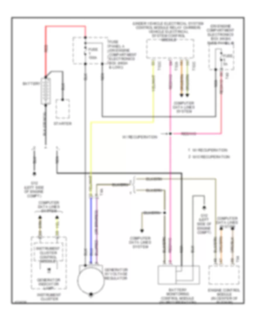
Vehicle Electrical System Control Module Wiring Diagram for Volkswagen CC R-Line 2014
List of elements for Vehicle Electrical System Control Module Wiring Diagram for Volkswagen CC R-Line 2014:
- (left kick panel) g639
- 26a
- 3.6l
- 40a
- 41a
- Anti-lock brakes & exterior light systems
- Anti-theft & interior lights systems
- Anti-theft system
- Computer data lines system
- Defogger system
- Door locks & anti-theft systems
- Door locks & interior lights systems
- Door locks, anti-theft & interior lights systems
- Engine controls system
- Exterior lights & mirrors systems
- Exterior lights & wiper/washer systems
- Exterior lights system
- Fuse 15a
- Fuse 20a
- Fuse 25a
- Fuse 40a
- Fuse 5a
- Fuse panel b (on engine compt electronics box (high))
- Fuse panel c (left end of dash)
- Fuse panel f (left rear of luggage compt)
- G639 (left kick panel)
- Headlights & exterior lights systems
- Headlights & interior lights systems
- Headlights system
- Horns system
- Hot at all times
- Hot w/ load reduction relay energized
- Interior lights system
- Power distribution system
- Red
- Starting/ charging system
- Starting/charging & anti-theft systems
- T2dp
- T40
- T52a
- T52b
- T52c
- Vehicle electrical system control module (under vehicle electrical system control module relay carrier)
- W/ recuperation
- Windshield washer pump relay
- Wiper/washer & headlights systems
- Wiper/washer system
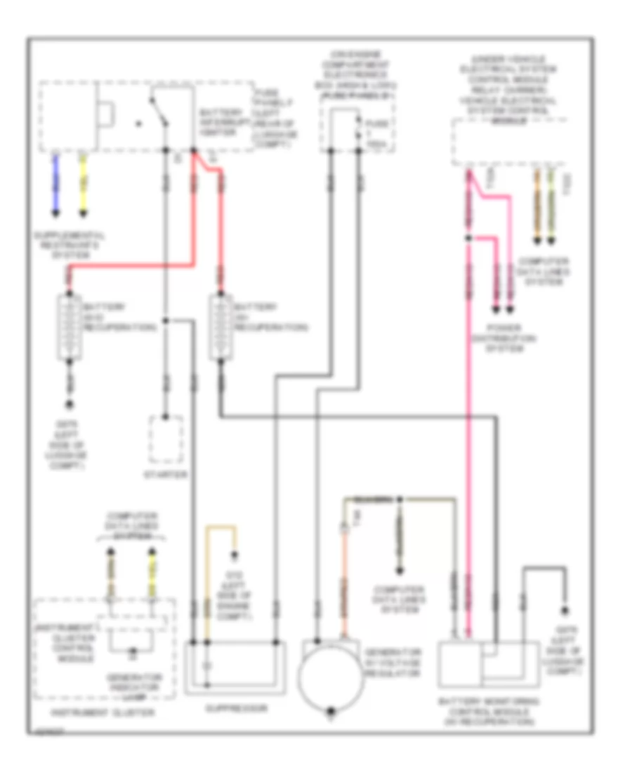
COMPUTER DATA LINES
Computer Data Lines Wiring Diagram (1 of 2) for Volkswagen CC R-Line 2014
List of elements for Computer Data Lines Wiring Diagram (1 of 2) for Volkswagen CC R-Line 2014:
- (forward of sunroof) sunroof control module
- (in interior rearview mirror retainer) rain/light recognition sensor
- (under vehicle electrical system control module relay carrier) vehicle electrical system control module
- 13a
- Analog clock
- Battery monitoring control module (w/ recuperation)
- Climatronic control module (integral to climatronic control head)
- Comfort system central control module (behind right side of dash)
- Data bus on board diagnostic interface (under left side of dash)
- Diagnostic connector (under left side of dash)
- Driver's door control module (in driver's door)
- Driver's seat adjustment control module
- Front passenger's door control module (in front passenger's door)
- Fuse 10a
- Fuse 5a
- Fuse panel b
- Fuse panel c (left end of dash)
- G639 (left kick panel)
- Generator w/ voltage regulator
- Hot at all times
- Instrument cluster
- Instrument cluster control module
- Left rear door control module (in left rear door)
- Power distribution system
- Right rear door control module (in right rear door)
- Steering column electronic systems control module (top of steering column)
- T10c
- T16o
- T18a
- T20c
- T20g
- T20h
- T28
- T28a
- T28b
- T28c
- T32f
- T40
- T4a
- T52b
- T52c
- Vehicle positioning system control module
- Wiper motor control module
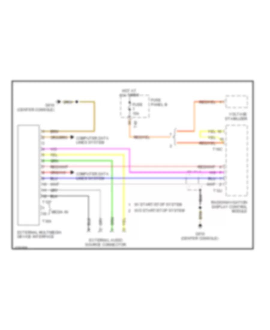
Computer Data Lines Wiring Diagram (2 of 2) for Volkswagen CC R-Line 2014
List of elements for Computer Data Lines Wiring Diagram (2 of 2) for Volkswagen CC R-Line 2014:
- (behind center of front grille) distance regulation control module
- (behind glove compt) headlight range/ cornering lamp control module
- (in center of plenum) engine control module (ecm)
- (integral to comfort system central control module) tire pressure monitoring control module
- (integral w/ steering gear assembly) power steering control module
- (left side of dash) parking aid control module
- (on rear differential) all-wheel drive control module
- Abs control module (on right side of firewall)
- Air bag control module (under front of center console)
- Amplifier
- Cell phone operating electronics & telephone control head control module (under right front seat)
- Cellular telephone preparation control head (if equipped)
- Compass magnetic field sensor (center of trunk lid)
- Dsg transmission mechatronic
- Electro-mechanical parking brake control module (rear of center tunnel)
- Electronic damping control module (right side of trunk)
- Emergency call module & communication control module
- External multimedia device interface
- Front camera driver assistance system
- Lane change assistance control module
- Left front headlamp
- Nca
- Parallel parking assistance control module (if equipped) (behind left side of dash)
- Radio/ navigation display unit control module (or) radio
- Rearview camera system control module (right side of luggage compt)
- Right front headlamp
- Selector lever
- T10a
- T10o
- T12y
- T16
- T16c
- T20m
- T23
- T3dt
- T6e
- T8z
- T94
- Transmission control module
- Tv tuner (if equipped) (right side of luggage compt)
COOLING FAN
Cooling Fan Wiring Diagram for Volkswagen CC R-Line 2014
List of elements for Cooling Fan Wiring Diagram for Volkswagen CC R-Line 2014:
- 10a
- 2.0l turbo
- 3.6l
- After-run coolant pump (lower left rear of engine)
- Computer data lines system
- Coolant circulation pump relay (2.0l turbo) (on relay carrier 1)
- Coolant circulation pump relay (3.6l)
- Coolant fan 2 (behind right side of radiator)
- Coolant fan control (fc) module (on radiator fan motor)
- Coolant m fan
- Engine control module (ecm) (in center of plenum)
- Engine coolant temperature (ect) sensor (2.0l: in coolant pump housing) (3.6l: left rear of engine)
- Engine coolant temperature (ect) sensor (on radiator) (lower left of radiator)
- Fuse
- Fuse 10a
- Fuse 50a
- Fuse panel a (on engine compt electronics box (high & low))
- Fuse panel b (on engine compt electronics box (high))
- G645 (on firewall)
- G671 (on left long member)
- G673 (on left long member)
- Hot at all times
- Nca
- Red
- T26a
- T2be
- T2ck
- T40
- T4a
- T4i
- T60
- T94
CRUISE CONTROL
Cruise Control Wiring Diagram (1 of 3) for Volkswagen CC R-Line 2014
List of elements for Cruise Control Wiring Diagram (1 of 3) for Volkswagen CC R-Line 2014:
- (behind center of front grille)
- (left kick panel) g639
- (top of
- Adaptive cruise control sensor & adaptive cruise control sensor heater
- Button
- Computer data lines system
- Control module
- Cruise control
- Cruise control deactivation
- Cruise control indicator lamp
- Cruise control main
- Cruise control set button
- Distance regulation control module
- Electronic systems
- Fuse 5a
- Fuse panel c (left end of dash)
- Instrument cluster
- Instrument cluster control module
- Multifunction indicator selection switch
- Nca
- Steering column
- Steering column combination switch
- Steering column)
- Switch
- T10a
- T16o
- Temporary
- Transmission control module (tcm) (w/o dsg transmission)
- Transmission input speed sensor & transmission output speed sensor (transmission input speed sensor: in transmission, near multi plate clutch) (transmission output speed sensor: in transmission, above valve body assembly)
- Trip computer reset button
Cruise Control Wiring Diagram (2 of 3) for Volkswagen CC R-Line 2014
List of elements for Cruise Control Wiring Diagram (2 of 3) for Volkswagen CC R-Line 2014:
- (on brake master cylinder) (2.0l turbo) brake light switch
- (on rear differential) all wheel drive control module
- (under vehicle electrical system control module relay carrier) (2.0l turbo) vehicle electrical system control module
- 2.0l turbo 3.6l
- Clutch oil temperature sensor/ transmission input speed (rpm) sensor (transmission input speed sensor: in transmission, above valve body assembly) (clutch oil temperature sensor: in transmission, near multi-plate clutch)
- Computer data lines system
- Drive shaft speed sensor 1
- Drive shaft speed sensor 2
- Dsg transmission mechatronic (w/ dsg transmission)
- Engine speed (rpm) sensor (left rear of engine)
- Fuse 10a
- Fuse 15a
- Fuse panel b (on engine compt electronics box)
- G639 (left kick panel)
- Hot at all times
- Nca
- Red
- T20m
- T40
- T4ah
- T52c
- T8z
- Throttle valve control module (on intake manifold assembly)
- Transmission output speed sensor
Cruise Control Wiring Diagram (3 of 3) for Volkswagen CC R-Line 2014
List of elements for Cruise Control Wiring Diagram (3 of 3) for Volkswagen CC R-Line 2014:
- (above accelerator pedal) accelerator pedal position sensor & accelerator pedal position sensor 2
- (left rear of engine) engine speed (rpm) sensor
- (top of clutch assembly) (m/t) clutch position sensor
- 2.0l turbo
- 3.6l
- A/t
- Accelerator pedal position sensor & accelerator pedal position sensor 2 (above accelerator pedal)
- All wheel drive control module (on rear differential)
- Brake light switch (3.6l) (on brake master cylinder)
- Cbfa
- Ccta
- Computer data lines system
- Electro- mechanical parking brake control module (rear of center tunnel)
- Engine control module (ecm) (2.0l turbo) (in center of plenum)
- Engine control module (ecm) (3.6l) (in center of plenum)
- Fuse 30a
- Fuse 40a
- Fuse panel b (on engine compt electronics box)
- G639 (left kick panel)
- G645 (firewall)
- Hot at all times
- M/t
- Nca
- Red
- T26a
- T40
- T52c
- T60
- T8z
- T94
- Vehicle electrical system control module (3.6l) (under vehicle electrical system control module relay carrier)
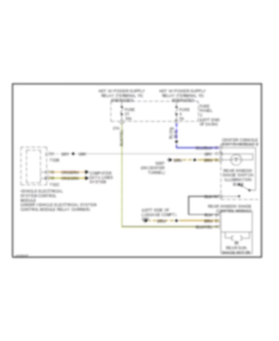
DEFOGGERS
Defoggers Wiring Diagram for Volkswagen CC R-Line 2014
List of elements for Defoggers Wiring Diagram for Volkswagen CC R-Line 2014:
- 12a
- 15a
- 32a
- 44a
- Climatronic control module (integral to climatronic control head)
- Computer data lines system
- Data bus on board diagnostic interface (under left side of dash)
- Driver's heated exterior rearview mirror
- Driver's side door control module (in driver's door)
- Exterior rearview mirror heating switch
- Front passenger's door control module (in front passenger's door)
- Front passenger's heated exterior rearview mirror
- Fuse 10a
- Fuse 30a
- Fuse 60a
- Fuse panel b (on engine compt electronics box (high))
- Fuse panel c (left end of dash)
- G638 (right kick panel)
- G657 (left "c" pillar)
- G684 (on left front side member)
- G689 (on center front roof)
- Hot at all times
- Interior lights system
- Mirror heater
- Nca
- Rear window defogger
- Rear window defogger relay (on vehicle electrical system control module relay carrier)
- T16k
- T16l
- T1a
- T1b
- T1y
- T20c
- T20e
- T20g
- T20h
- T28
- T28c
- T32a
- T40
- T52b
- Vehicle electrical system control module (under vehicle electrical system t52c control module relay carrier)
- Windshield defogger
- Windshield defroster relay
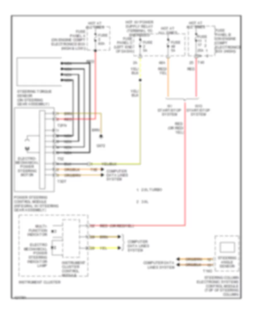
ELECTRONIC POWER STEERING
Electronic Power Steering Wiring Diagram for Volkswagen CC R-Line 2014
List of elements for Electronic Power Steering Wiring Diagram for Volkswagen CC R-Line 2014:
- 2.0l turbo
- 25a
- 3.6l
- 48a
- Computer data lines system
- Electro mechanical power steering indicator lamp
- Electro- mechanical power steering motor
- Fuse
- Fuse 5a
- Fuse 80a
- Fuse panel a (on engine compt electronics box (high & low))
- Fuse panel b (on engine compt electronics box (high))
- Fuse panel c (left end of dash)
- G672
- Hot at all times
- Instrument cluster
- Instrument cluster control module
- Multi- function indicator
- Nca
- Power steering control module (integral w/ steering gear assembly)
- Red
- Steering angle sensor
- Steering column electronic systems control module (top of steering column)
- Steering torque sensor (on steering gear assembly)
- T16o
- T2fn
- T3dt
- T40
- T5z
- T6e
- W/ start/stop system
- W/o start/stop system
ELECTRONIC SUSPENSION
Electronic Suspension Wiring Diagram for Volkswagen CC R-Line 2014
List of elements for Electronic Suspension Wiring Diagram for Volkswagen CC R-Line 2014:
- Center console switch module 2
- Computer data lines system
- Damping adjustment button
- Damping adjustment indicator lamp
- Electronic damping control module (right side of trunk)
- Fuse 15a
- Fuse 5a
- Fuse panel c (left end of dash)
- Fuse panel d (under right end of dash)
- G51 (right side of luggage compt)
- Hot at all times
- Interior lights system
- Left front body acceleration sensor (on left front strut)
- Left front dampening adjustment valve (on left front shock absorber assemblies)
- Left front level control system sensor (in left front wheelwell)
- Left rear dampening adjustment valve (on left rear shock absorber assemblies)
- Left rear level control system sensor (in left rear wheelwell)
- Pnk
- Push button illumination bulb
- Rear body acceleration sensor (mounted on left rear strut)
- Red
- Right front body acceleration sensor (top of right front strut)
- Right front dampening adjustment valve (on right front shock absorber assemblies)
- Right front level control system sensor (in right front wheelwell)
- Right rear dampening adjustment valve (on right rear shock absorber assemblies)
ENGINE PERFORMANCE
2.0L TURBO
2.0L Turbo, Engine Performance Wiring Diagram, CBFA (1 of 6) for Volkswagen CC R-Line 2014
List of elements for 2.0L Turbo, Engine Performance Wiring Diagram, CBFA (1 of 6) for Volkswagen CC R-Line 2014:
- A/t
- Cooling fans system
- Dsg transmission mechatronic (if equipped)
- Engine control module (ecm) (in center of plenum)
- Engine coolant temperature sensor (on radiator) (lower left of radiator)
- Fuse 10a
- Fuse 30a
- Fuse 50a
- Fuse 5a
- Fuse panel b (on engine compt electronics box (high))
- G645 (firewall)
- G647 (firewall)
- Hot at all times
- Leak detection pump (ldp) (usa) (in right rear wheelwell)
- M/t
- Mass air flow sensor (on engine air intake duct)
- Nca
- Oxygen sensor after three way catalytic converter (twc)/ heater oxygen sensor 1 after catalytic converter
- Red
- Secondary air injection pump motor (behind left front wheewell liner)
- Starting/charging system
- Steering column electronic systems control module (top of steering column)
- T16o
- T40
- T94
- W/ adaptive cruise control
2.0L Turbo, Engine Performance Wiring Diagram, CBFA (2 of 6) for Volkswagen CC R-Line 2014
List of elements for 2.0L Turbo, Engine Performance Wiring Diagram, CBFA (2 of 6) for Volkswagen CC R-Line 2014:
- (before three way converter (twc)) heater oxygen sensor 2 after catalytic converter & heated oxygen sensor 2
- (in fuel delivery unit) transfer fuel pump/ fuel level sensor
- (under vehicle electrical system control module relay carrier) vehicle electrical system control module
- 10a
- 27a
- Accelerator pedal position sensor & accelerator pedal position sensor 2 (above accelerator pedal)
- Coolant fan
- Coolant fan 2 (behind right side of radiator)
- Coolant fan control module (on radiator fan motor)
- Engine coolant level sensor (in expansion tank)
- Fuse 10a
- Fuse 20a
- Fuse panel c (left end of dash)
- G671 (left long member)
- Heated oxygen sensor (ho2s) & oxygen sensor heater (on exhaust manifold)
- Hot at all times
- Nca
- Red
- T2be
- T4i
- T52b
- T52c
2.0L Turbo, Engine Performance Wiring Diagram, CBFA (3 of 6) for Volkswagen CC R-Line 2014
List of elements for 2.0L Turbo, Engine Performance Wiring Diagram, CBFA (3 of 6) for Volkswagen CC R-Line 2014:
- (in fuel delivery unit) fuel pump (fp) control module
- Computer data lines system
- Electronic power control malfunction indicator lamp
- Engine control module (ecm) (in center of plenum)
- Engine coolant level/ temperature indicator lamp
- Engine coolant temperature (ect) gauge
- Fuel gauge
- G78 (right lower "b" pillar)
- Instrument cluster
- Instrument cluster control module
- Low fuel level indicator lamp
- Oil level indicator lamp
- Oil pressure indicator lamp
- Red
- T94
- Tachometer
2.0L Turbo, Engine Performance Wiring Diagram, CBFA (4 of 6) for Volkswagen CC R-Line 2014
List of elements for 2.0L Turbo, Engine Performance Wiring Diagram, CBFA (4 of 6) for Volkswagen CC R-Line 2014:
- Brake light switch (on brake master cylinder)
- Charge air pressure sender/ manifold absolute pressure sensor (on charge air tube)
- Clutch position sensor (m/t) (top of clutch assembly)
- Electro-mechanical parking brake control module (rear of center tunnel)
- Fuel pump relay 2
- Fuse 50a
- Fuse panel a (on engine compt electronics box (high & low))
- G639 (left kick panel)
- G645 (firewall)
- Hot at all times
- Intake manifold runner position sensor (front of intake manifold)
- Oil pressure switch (on oil filter assembly)
- T14a
- T6bu
2.0L Turbo, Engine Performance Wiring Diagram, CBFA (5 of 6) for Volkswagen CC R-Line 2014
List of elements for 2.0L Turbo, Engine Performance Wiring Diagram, CBFA (5 of 6) for Volkswagen CC R-Line 2014:
- (attached to intake manifold) evaporative emission (evap) canister purge regulator valve 1
- (front of cylinder head) camshaft adjustment valve 1
- (left rear of engine) secondary air injection solenoid valve
- (on fuel rail)
- (on intake manifold) intake manifold runner control (imrc) valve
- (on turbocharger) turbocharger recirculation valve
- (on turbocharger) wastegate bypass regulator valve
- Camshaft position (cmp) sensor (left side of cylinder head)
- Engine coolant temperature (ect) sensor (in coolant pump housing)
- Fuel injector cylinder 1
- Fuel injector cylinder 2
- Fuel injector cylinder 3
- Fuel injector cylinder 4
- Fuel pressure sensor (on fuel rail)
- Intake air temperature sensor (front of intake manifold assembly)
- Knock sensor 1 (below intake manifold)
- Nca
- Secondary air injection sensor 1 (on outlet of secondary air injection pump motor)
- T14a
- T6bu
- T8y
2.0L Turbo, Engine Performance Wiring Diagram, CBFA (6 of 6) for Volkswagen CC R-Line 2014
List of elements for 2.0L Turbo, Engine Performance Wiring Diagram, CBFA (6 of 6) for Volkswagen CC R-Line 2014:
- (left rear of engine) engine speed sensor
- (on mechanical high pressure pump) fuel pressure regulator valve
- (top of cylinders)
- Engine control module (ecm) (in center of plenum)
- Epc throttle drive & epc throttle drive angle sensor 1 & 2 (on throttle control module)
- G15 (top of cylinder head)
- G673 (left long member)
- Ignition coil 1 w/ power output stage
- Ignition coil 2 w/ power output stage
- Ignition coil 3 w/ power output stage
- Ignition coil 4 w/ power output stage
- Nca
- Red
- T14a
- T60
- To spark plug
2.0L Turbo, Engine Performance Wiring Diagram, CCTA (1 of 6) for Volkswagen CC R-Line 2014
List of elements for 2.0L Turbo, Engine Performance Wiring Diagram, CCTA (1 of 6) for Volkswagen CC R-Line 2014:
- A/t
- Cooling fans system
- Dsg transmission mechatronic (if equipped)
- Engine control module (ecm) (in center of plenum)
- Engine coolant temperature sensor (on radiator) (lower left of radiator)
- Fuse 10a
- Fuse 30a
- Fuse 50a
- Fuse 5a
- Fuse panel b (on engine compt electronics box (high))
- G645 (firewall)
- G647 (firewall)
- Hot at all times
- Leak detection pump (ldp) (usa) (in right rear wheelwell)
- M/t
- Mass air flow sensor (on engine air intake duct)
- Nca
- Oxygen sensor after three way catalytic converter (twc)/ heater oxygen sensor 1 after catalytic converter
- Red
- Reduced oil pressure switch
- Secondary air injection pump motor (behind left front wheelwell liner)
- Starting/ charging system
- Starting/charging system
- Steering column electronic systems control module (top of steering column)
- T14a
- T16o
- T40
- T94
- W/ adaptive cruise control
2.0L Turbo, Engine Performance Wiring Diagram, CCTA (2 of 6) for Volkswagen CC R-Line 2014
List of elements for 2.0L Turbo, Engine Performance Wiring Diagram, CCTA (2 of 6) for Volkswagen CC R-Line 2014:
- (before three way converter (twc)) heater oxygen sensor 2 after catalytic converter/ heated oxygen sensor 2
- (in fuel delivery unit) transfer fuel pump/ fuel level sensor
- (under vehicle electrical system control module relay carrier) vehicle electrical system control module
- 10a
- 27a
- Accelerator pedal position sensor & accelerator pedal position sensor 2 (above accelerator pedal)
- Coolant fan
- Coolant fan 2 (behind right side of radiator)
- Coolant fan control module (on radiator fan motor)
- Engine coolant level sensor (in expansion tank)
- Fuse 10a
- Fuse 20a
- Fuse panel c (left end of dash)
- G671 (left long member)
- Heated oxygen sensor (ho2s) (on exhaust manifold)
- Hot at all times
- Nca
- Red
- T2be
- T4i
- T52b
- T52c
2.0L Turbo, Engine Performance Wiring Diagram, CCTA (3 of 6) for Volkswagen CC R-Line 2014
List of elements for 2.0L Turbo, Engine Performance Wiring Diagram, CCTA (3 of 6) for Volkswagen CC R-Line 2014:
- (in fuel delivery unit) fuel pump (fp) control module
- Computer data lines system
- Electronic power control malfunction indicator lamp
- Engine control module (ecm) (in center of plenum)
- Engine coolant level/ temperature indicator lamp
- Engine coolant temperature (ect) gauge
- Fuel gauge
- G639 (left kick panel)
- G78 (right lower "b" pillar)
- Instrument cluster
- Instrument cluster control module
- Low fuel level indicator lamp
- Oil level indicator lamp
- Oil level thermal sensor (bottom of engine oil pan)
- Oil pressure indicator lamp
- Red
- T6e
- T94
- Tachometer
2.0L Turbo, Engine Performance Wiring Diagram, CCTA (4 of 6) for Volkswagen CC R-Line 2014
List of elements for 2.0L Turbo, Engine Performance Wiring Diagram, CCTA (4 of 6) for Volkswagen CC R-Line 2014:
- (w/ emissions standard bin5/ulev) fuel pump relay 2
- Box (high & low))
- Brake light switch (on brake master cylinder)
- Charge air pressure sensor/ manifold absolute pressure sensor (on charge air tube)
- Clutch position sensor (m/t) (top of clutch assembly)
- Electro-mechanical parking brake control module (rear of center tunnel)
- Fuse 50a
- Fuse panel a (on engine compt electronics
- G639 (left kick panel)
- G645 (firewall)
- Hot at all times
- Intake manifold runner position sensor (front of intake manifold)
- Oil pressure switch (on oil filter assembly)
- T14a
- T6bu
2.0L Turbo, Engine Performance Wiring Diagram, CCTA (5 of 6) for Volkswagen CC R-Line 2014
List of elements for 2.0L Turbo, Engine Performance Wiring Diagram, CCTA (5 of 6) for Volkswagen CC R-Line 2014:
- (attached to intake manifold) evaporative emission (evap) canister purge regulator valve 1
- (front of cylinder head) camshaft adjustment valve 1
- (in oil pan) oil pressure regulation valve
- (on fuel rail)
- (on intake manifold) intake manifold runner control (imrc) valve
- (on turbocharger) turbocharger recirculation valve
- (on turbocharger) wastegate bypass regulator valve
- Camshaft position (cmp) sensor (left side of cylinder head)
- Cylinder 1
- Cylinder 4
- Engine coolant temperature (ect) sensor (in coolant pump housing)
- Fuel injectors
- Fuel injectors cylinder 2
- Fuel injectors cylinder 3
- Fuel pressure sensor (on fuel rail)
- Intake air temperature sensor (front of intake manifold assembly)
- Knock sensor 1 (below intake manifold)
- Nca
- T14a
- T6bu
- T8y
2.0L Turbo, Engine Performance Wiring Diagram, CCTA (6 of 6) for Volkswagen CC R-Line 2014
List of elements for 2.0L Turbo, Engine Performance Wiring Diagram, CCTA (6 of 6) for Volkswagen CC R-Line 2014:
- (left rear of engine) engine speed sensor
- (on mechanical high pressure pump) fuel pressure regulator valve
- (top of cylinders)
- Engine control module (ecm) (in center of plenum)
- Epc throttle drive & epc throttle drive angle sensor 1 & 2 (on throttle control module)
- G15 (top of cylinder head)
- G673 (left long member)
- Ignition coil 1 w/ power output stage
- Ignition coil 2 w/ power output stage
- Ignition coil 3 w/ power output stage
- Ignition coil 4 w/ power output stage
- Nca
- Red
- T14a
- T60
- To spark plug
3.6L
3.6L, Engine Performance Wiring Diagram (1 of 6) for Volkswagen CC R-Line 2014
List of elements for 3.6L, Engine Performance Wiring Diagram (1 of 6) for Volkswagen CC R-Line 2014:
- Brake light switch (on brake master cylinder)
- Cooling fans system
- Electronic ignition switch
- Engine control module (ecm) (in center of plenum)
- Engine coolant temperature (ect) sensor (radiator) (lower left of radiator)
- Fuse 10a
- Fuse 15a
- Fuse 20a
- Fuse 30a
- Fuse 40a
- Fuse 5a
- Fuse panel b (on engine compt electronics box (high))
- G639 (left kick panel)
- G645 (firewall)
- Hot at all times
- Leak detection pump (usa) (in right rear wheelwell)
- Multi-function transmission range switch (a/t) (on top of transmission)
- Nca
- Red
- Starting/ charging system
- Steering column electronic control module (top of steering column)
- T14a
- T16o
- T26a
- T40
- T94
- W/ adaptive cruise control
3.6L, Engine Performance Wiring Diagram (2 of 6) for Volkswagen CC R-Line 2014
List of elements for 3.6L, Engine Performance Wiring Diagram (2 of 6) for Volkswagen CC R-Line 2014:
- (under vehicle electrical system control module relay carrier) vehicle electrical system control module
- 10a
- 27a
- Accelerator pedal position sensor 2 & accelerator pedal position sensor (above accelerator pedal)
- Fuse 10a
- Fuse 20a
- Fuse 5a
- Fuse panel c (left end of dash)
- Heated oxygen (ho2s) sensor (before right three way converter (twc))
- Heated oxygen (ho2s) sensor 2 (before left three way converter (twc))
- Hot at all times
- Mass air flow (maf) sensor/ intake air temperature (iat) sensor (on engine air intake duct)
- Nca
- Red
- T14a
- T52b
- T52c
3.6L, Engine Performance Wiring Diagram (3 of 6) for Volkswagen CC R-Line 2014
List of elements for 3.6L, Engine Performance Wiring Diagram (3 of 6) for Volkswagen CC R-Line 2014:
- (in fuel delivery unit) fuel pump (fp) control module
- (in fuel delivery unit) transfer fuel pump (fp)/ fuel level sensor
- Computer data lines system
- Electronic power control malfunction indicator lamp
- Engine control module (ecm) (in center of plenum)
- Engine coolant level/ temperature indicator lamp
- Engine coolant temperature (ect) gauge
- Fuel gauge
- G639 (left kick panel)
- G78 (right lower "b" pillar)
- Instrument cluster
- Instrument cluster control module
- Low fuel level indicator lamp
- Oil level indicator lamp
- Oil level thermal sensor (bottom of engine oil pan)
- Oil pressure indicator lamp
- Oil pressure switch (on oil filter assembly)
- Red
- Starting/ charging system
- T14a
- T6e
- T94
- Tachometer
3.6L, Engine Performance Wiring Diagram (4 of 6) for Volkswagen CC R-Line 2014
List of elements for 3.6L, Engine Performance Wiring Diagram (4 of 6) for Volkswagen CC R-Line 2014:
- Coolant fan
- Coolant fan 2 (behind right side of radiator)
- Coolant fan control (fc) module (on radiator fan motor)
- Engine coolant level sensor (in expansion tank)
- Fuel level sensor 2 (awd) (top of fuel tank)
- Fuse 50a
- Fuse panel a (on engine compt electronics box (high & low))
- G671 (left long member)
- Hot at all times
- Nca
- Oxygen sensor 2 after catalytic converter/ oxygen sensor 2
- Oxygen sensor after three way catalytic converter/ oxygen sensor 1
- Positive crankcase ventilation (pcv) heating element (on intake manifold)
- Red
- T14a
- T2be
- T4i
3.6L, Engine Performance Wiring Diagram (5 of 6) for Volkswagen CC R-Line 2014
List of elements for 3.6L, Engine Performance Wiring Diagram (5 of 6) for Volkswagen CC R-Line 2014:
- (on mechanical high pressure pump) fuel pressure regulator valve
- (rear of engine) camshaft adjustment valve 1
- (rear of engine) camshaft adjustment valve 1 (exhaust)
- (rear of right cylinder bank) camshaft position (cmp) sensor 2
- (right front of engine) low fuel pressure sensor
- Camshaft position (cmp) sensor (rear of left cylinder bank)
- Engine coolant temperature (ect) sensor (left rear of engine)
- Engine speed (rpm) sensor (left rear of engine)
- Epc throttle drive angle sensor 1 & 2 (on throttle control module)
- Evaporative emission (evap) canister purge regulator valve 1
- Fuel pressure sensor (rear of left fuel rail)
- Knock sensor (ks) 1 (between cylinders 1 & 3)
- Knock sensor (ks) 2 (between cylinders 4 & 6)
- Nca
- Red
3.6L, Engine Performance Wiring Diagram (6 of 6) for Volkswagen CC R-Line 2014
List of elements for 3.6L, Engine Performance Wiring Diagram (6 of 6) for Volkswagen CC R-Line 2014:
- (top of left bank cylinder) fuel injector cylinder 2
- (top of left bank cylinder) fuel injector cylinder 4
- (top of left bank cylinder) fuel injector cylinder 6
- (top of right bank cylinder) fuel injector cylinder 1
- (top of right bank cylinder) fuel injector cylinder 3
- (top of right bank cylinder) fuel injector cylinder 5
- Engine control module (ecm) (in center of plenum)
- G15 (top of cylinder head)
- G673 (left long member)
- Ignition coil w/ power output stage (top of cylinders)
- Nca
- Red
- T60
- To spark plug
EXTERIOR LIGHTS
Backup Lamps Wiring Diagram for Volkswagen CC R-Line 2014
List of elements for Backup Lamps Wiring Diagram for Volkswagen CC R-Line 2014:
- (in direct shift transmission valve body) (w/ dual clutch transmission) backup light switch
- 39a
- Automatic dimming rearview interior mirror
- Automatic transmission control module (3.6l) (in left front wheelwell)
- Backup lamp
- Computer data lines system
- Dsg transmission mechatronic (2.0l turbo) (in direct shift gearbox)
- Engine control module (in center of plenum)
- Fuse 5a
- Fuse panel c (left end of dash)
- G50 (left side of luggage compt)
- G673 (left long member)
- Left tail lamp 2
- Multi-function transmission range switch (on top of transmission)
- Nca
- Right tail lamp 2
- T20m
- T2ke
- T2kf
- T52a
- T52c
- T94
- Transmissions system
- Vehicle electrical system control module (under vehicle electrical system control module relay carrier)
Exterior Lamps Wiring Diagram (1 of 3) for Volkswagen CC R-Line 2014
List of elements for Exterior Lamps Wiring Diagram (1 of 3) for Volkswagen CC R-Line 2014:
- 13a
- 2.0l turbo
- 3.6l
- All wheel drive control module (on rear differential)
- Backup lamps circuit
- Brake light switch (on brake master cylinder)
- Computer data lines
- Computer data lines system
- Engine control module (ecm) (in center of plenum)
- Fog lamp switch
- Fuse 10a
- Fuse 20 fuse 8 5a 10a
- Fuse 40a
- Fuse 5a
- Fuse panel b (on engine compt electronics box (high))
- Fuse panel c (left end of dash)
- G50 (left side of luggage compt)
- G639 (left kick panel)
- G673 (left long member)
- G685 (on right front long member)
- Hot at all times
- Hot w/ motronic engine control module
- Left backup lamp
- Left taillamp 2
- Left taillight
- Light switch
- Rear fog lamp switch
- Red
- Right adaptive cornering lamp motor
- Right backup lamp
- Right daytime running lamp & position lamp control module
- Right daytime running lamp & position lamp led module
- Right front headlamp (w/ hid)
- Right front turn signal lamp
- Right position lamp
- Right tail lamp 2
- Right taillight
- System
- T14c
- T2j
- T2kf
- T40
- T52a
- T52b
- T52c
- T94
- Vehicle electrical system control module (under vehicle electrical system control module relay carrier)
- W/ dynamic cornering lamp
- W/ hid
- W/o hid
Exterior Lamps Wiring Diagram (2 of 3) for Volkswagen CC R-Line 2014
List of elements for Exterior Lamps Wiring Diagram (2 of 3) for Volkswagen CC R-Line 2014:
- Computer data lines system
- Driver exterior rearview mirror turn signal lamp
- Driver's door control module (in driver's door)
- Driver's outside mirror
- Front passenger exterior rearview mirror turn signal lamp
- Front passenger's door control module (in front passenger's door)
- Front passenger's outside mirror
- Fuse 10a
- Fuse panel c (left end of dash)
- G673 (left long member)
- Instrument cluster
- Instrument cluster control module
- Lamp failure ind lamp
- Left adaptive cornering lamp motor
- Left daytime running lamp & position lamp control module
- Left daytime running lamp & position lamp led module
- Left front headlamp (w/ hid)
- Left front turn signal lamp
- Left position lamp
- Left turn signal ind
- Nca
- Position lamp ind
- Right turn signal ind
- Steering column combination switch
- Steering column electronic systems control module (top of steering column)
- T14c
- T16k
- T16l
- T16o
- T20g
- T20h
- Trailer operation ind lamp
- Turn signal switch
- W/ dynamic cornering lamp
- W/ hid
- W/o hid
Exterior Lamps Wiring Diagram (3 of 3) for Volkswagen CC R-Line 2014
List of elements for Exterior Lamps Wiring Diagram (3 of 3) for Volkswagen CC R-Line 2014:
- Emergency flasher switch
- G50 (left side of luggage compt)
- G51 (right side of luggage compt)
- G639 (left kick panel)
- G673 (left long member)
- G685 (on right front long member)
- High mounted brake lamp
- Left brake/ tail lamp
- Left brake/ tail lamp 2
- Left front headlamp (w/o hid)
- Left license plate lamp
- Left rear turn signal lamp
- Left tail lamp
- Position lamp
- Right brake/ tail lamp
- Right brake/ tail lamp 2
- Right front headlamp (w/o hid)
- Right license plate lamp
- Right rear turn signal lamp
- Right tail lamp
- Stationary cornering lamp
- T3an
GROUND DISTRIBUTION
Ground Distribution Wiring Diagram (1 of 5) for Volkswagen CC R-Line 2014
List of elements for Ground Distribution Wiring Diagram (1 of 5) for Volkswagen CC R-Line 2014:
- (2.0l turbo) secondary air injection pump motor
- (3.6l)
- (3.6l) battery monitoring control module
- (automatic a/c) fresh air blower control module
- (if equipped) auxiliary battery charging relay
- (if equipped) left footwell light
- (if equipped) right footwell light
- (w/ parallel parking assistance) parallel parking assistance control module (w/o parallel parking assistance) parking aid control module
- (w/ start/ stop system) steering column electronics control module
- Access/ start authorization switch
- Alarm horn
- Auxiliary battery
- Battery
- Brake fluid level warning switch
- Brake light switch
- Comfort system central control module
- Data bus on board diagnostic interface
- Distance regulation control module
- Driver assistance system front camera
- Electronic steering column lock control module
- Emergency flasher switch & emergency flasher indicator lamp
- Front passenger window lowering micro switch
- Front passenger's door control module
- Front passenger's outside door handle touch sensor, central locking button & acess/start authorization antenna
- G42 (near steering column)
- G638 (right kick panel)
- G639 (left kick panel)
- G647 (firewall)
- G676 (left side of luggage compt)
- Glove compartment lamp
- Headlamp range control module
- Instrument cluster
- Instrument panel & switch illumination dimmer switch
- Left front brake pad wear sensor
- Left front sill panel ambient lighting fiber optic cable
- Light switch
- Load reduction relay
- Oil level thermal sensor
- Right front sill panel ambient lighting fiber optic cable
- Steering column electronic systems control module
- T10a
- T10f
- T16
- T16o
- T18a
- T20h
- T28
- T2xi
- T2xj
- T52a
- T52b
- T52c
- T6e
- Terminal & engine start control system
- Vehicle electrical system control module
- Wiper motor control module
Ground Distribution Wiring Diagram (2 of 5) for Volkswagen CC R-Line 2014
List of elements for Ground Distribution Wiring Diagram (2 of 5) for Volkswagen CC R-Line 2014:
- (w/o hid) left front turn signal lamp
- (w/o hid) right front turn signal lamp
- 2.0l turbo
- 3.6l
- A/c compressor regulator valve
- After-run coolant pump
- All-wheel drive control module
- Coolant fan control module
- Dsg transmission mechatronic
- G15 (top of cylinder head)
- G50 (left side of luggage compt)
- G671 (left long member)
- G673 (left long member)
- G77 (left lower "b" pillar)
- High tone horn
- High-mount brake lamp
- Ignition coil 1 (w/ power output stage)
- Ignition coil 2 (w/ power output stage)
- Ignition coil 3 (w/ power output stage)
- Ignition coil 4 (w/ power output stage)
- Ignition coil 5 (w/ power output stage)
- Ignition coil 6 (w/ power output stage)
- Left front fog lamp
- Left front headlamp
- Left rear door control module
- Left rear exterior door handle touch sensor & central locking button
- Left tail lamp
- Left tail lamp 2
- Multifunction transmission range switch
- Nca
- Rear lid handle release button
- Rear lid lock unit
- Rear window shade control module
- Right front fog lamp
- Right tail lamp2
- T14a
- T14c
- T14i
- T16r
- T20m
- T28a
- T2f
- T4a
- T8z
- Transmission control module (tcm)
- Vehicle positioning system control module
- W/ hid
- W/ rearview camera
- W/o rearview camera
Ground Distribution Wiring Diagram (3 of 5) for Volkswagen CC R-Line 2014
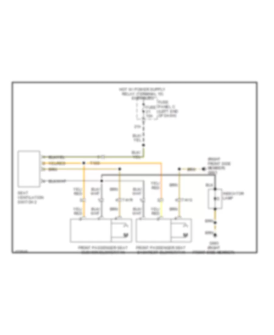
List of elements for Ground Distribution Wiring Diagram (3 of 5) for Volkswagen CC R-Line 2014:
- (if equipped) rear seat heating control module
- Control module for emergency call module & communication unit
- Driver acess/start system antenna, exterior door handle locking button & exterior door handle touch sensor
- Driver seat backrest blower fan
- Driver seat cushion blower fan
- Driver window lowering micro switch
- Driver's backrest heating element
- Driver's heated seat temperature sensor/seat heating element
- Driver's seat adjustment control module
- Driver's seat adjustment switch
- Driver's seat lumbar support adjustment switch
- Driver's side door control module
- Emergency call button
- Front passenger seat adjustment switch
- Front passenger seat backrest blower fan
- Front passenger seat cushion blower fan
- Front passenger seat lumbar support adjustment switch
- Front passenger's backrest heating element
- Front passenger's heated seat temperature sensor/seat heating element
- Front seat heating control module
- G683 (right front side member)
- G684 (on left front side member)
- Indicator lamp
- Seat ventilation switch
- Seat ventilation switch 2
- T10c
- T10d
- T12ab
- T20g
- T26j
- T28c
- T4vo
- T4vp
- T4vq
- T4vr
- T6dc
- T6dd
Ground Distribution Wiring Diagram (4 of 5) for Volkswagen CC R-Line 2014
List of elements for Ground Distribution Wiring Diagram (4 of 5) for Volkswagen CC R-Line 2014:
- (2.0l turbo) after run coolant pump
- (if equipped) cell phone operating electronics control module & telephone control head module
- (if equipped) cellular telephone preparation control head
- (if equipped) headlamp washer pump
- (if equipped) left washer nozzle heater
- (if equipped) right washer nozzle heater
- (if equipped) telephone base plate
- (m/t) clutch position sensor
- Air quality sensor
- Analog clock
- Automatic dimming interior rearview mirror
- Center console switch module 1
- Center console switch module 2
- Center instrument panel vent illumination bulb
- Cigarette lighter
- Climatronic control module
- Converter w/ socket 12v-115v
- Driver vanity mirror lamp contact switch
- Emergency call button
- Engine control module (ecm)
- Engine hood contact switch
- Front interior lamp
- Front passenger vanity mirror lamp contact switch
- G645 (firewall)
- G646 (firewall)
- G685 (on right front long member)
- G687 (on center tunnel)
- G689 (on center front roof)
- Garage door opener control head
- High pressure sensor
- If equipped
- Left instrument panel vent illumination bulb
- Left rear heated seat regulating switch
- Low tone horn
- Nca
- Rain/light recognition sensor
- Rear cigarette lighter
- Rear interior lamp
- Right front headlamp
- Right instrument panel vent illumination bulb
- Right rear heated seat regulating switch
- Selector lever
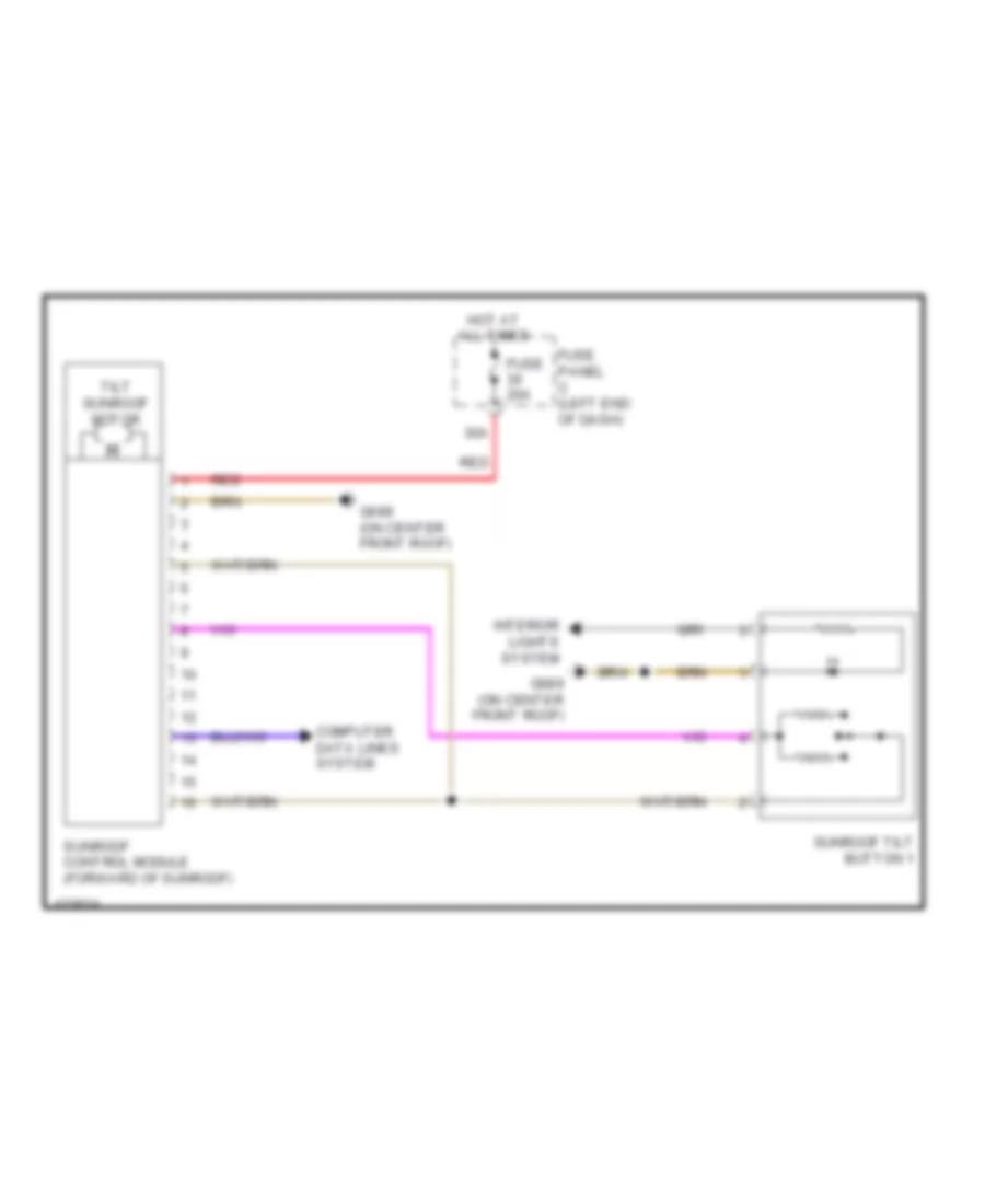
- Sunroof control module
- Sunroof tilt button 1
- T10e
- T10o
- T12ac
- T20c
- T2ck
- T94
- Tiptronic switch
- W/ hid
- Window defogger front sensor system
- Windshield defogger
Ground Distribution Wiring Diagram (5 of 5) for Volkswagen CC R-Line 2014
List of elements for Ground Distribution Wiring Diagram (5 of 5) for Volkswagen CC R-Line 2014:
- (2.0l turbo) battery monitoring control module
- (3.6l) suppressor
- (if equipped) cd changer
- (if equipped) tv tuner
- (w/ multi media socket) external audio source connection
- (w/ navigation) radio/ navigation display unit control module
- (w/ radio navigation system rns 315) telephone base plate
- (w/ tv tuner) rearview camera system control module
- (w/o navigation) radio
- (w/o tv reception) rearview camera system control module
- 12v socket
- Abs control module
- Amplifier
- Battery (2.0l turbo)
- Compass magnetic field sensor
- Electro-mechanical parking brake control module
- Electronic damping control module
- External multimedia device interface
- External multimedia device interface shield
- Fuel filler door unlock motor
- Fuel pump control module
- G12 (left side of engine compt)
- G13 (right side of engine compt)
- G51 (right side of luggage compt)
- G610 (center console)
- G652 (left side of engine compt)
- G657 (left "c" pillar)
- G672
- G688 (on center tunnel)
- G78 (right lower "b" pillar)
- Lane change assistance control module
- Lane change assistance control module 2
- Left license plate light
- Left rear backrest heating element & seat backrest temperature sensor
- Left rear heated seat temperature sensor & bench seat heating element
- Nca
- Power steering control module
- Rear lid opener control module
- Rear window defogger
- Right license plate light
- Right rear door control module
- Right rear exterior door handle touch sensor & central locking button
- Right rear heated seat temperature sensor & bench seat heating element
- Right rear seat backrest temperature sensor & seat backrest heating element
- Right tail lamp
- T10av
- T12y
- T16c
- T23
- T28b
- T2fn
- T3an
- T4hk
- T4hl
- T8d
- Tire pressure monitoring control module
- W/ parallel parking assistance
- W/ park distance control (pdc)
HEADLIGHTS
Headlights Wiring Diagram, with HID Headlamps (1 of 2) for Volkswagen CC R-Line 2014
List of elements for Headlights Wiring Diagram, with HID Headlamps (1 of 2) for Volkswagen CC R-Line 2014:
- (left kick panel) g639
- 13a
- 15a
- 40a
- Computer data lines system
- Fog lamp switch
- Fuse 10a
- Fuse 25a
- Fuse 5a
- Fuse panel c (left end of dash)
- G639 (left kick panel)
- G685 (on right front long member)
- G689 (on center front roof)
- Headlamp switch illumination bulb
- High beam ind lamp
- Hot at all times
- Hot w/ load reduction relay energized
- Instrument cluster
- Instrument cluster control module
- Instrument panel & switch illumination dimmer switch
- Light switch
- Rain/light recognition sensor (in interior rearview mirror retainer)
- Rear fog lamp ind lamp
- Rear fog lamp switch
- Right adaptive cornering lamp motor
- Right daytime running lamp & position lamp control module
- Right daytime running lamp & position lamp led module
- Right front headlamp
- Right front turn signal bulb
- Right headlamp beam adjustment motor
- Right headlamp power output stage
- Right hid headlamp bulb
- Right hid headlamp control module
- Right low beam headlamp reflector motor
- Right position lamp bulb
- Steering column electronic systems control module (top of steering column)
- T16o
- T52a
- T52b
- T52c
- Vehicle electrical system control module (under vehicle electrical system control module relay carrier)
- W/ dynamic cornering lamp
- Wiper motor control module
Headlights Wiring Diagram, with HID Headlamps (2 of 2) for Volkswagen CC R-Line 2014
List of elements for Headlights Wiring Diagram, with HID Headlamps (2 of 2) for Volkswagen CC R-Line 2014:
- (rear of center tunnel) electro-mechanical parking brake control module
- Computer data lines system
- Electro-mechanical parking brake button
- Fuse 10a
- Fuse 5a
- Fuse panel c (left end of dash)
- G50 (left side of luggage compt)
- G638 (right kick panel)
- G673 (left long long member)
- G673 (left long member)
- Headlight range/cornering lamp control module (behind glove compt)
- Left adaptive cornering lamp motor
- Left daytime running lamp & position lamp control module
- Left daytime running lamp & position lamp led module
- Left front fog lamp bulb
- Left front headlamp
- Left front turn signal bulb
- Left headlamp beam adjustment motor
- Left headlamp power output stage
- Left hid headlamp bulb
- Left hid headlamp control module
- Left low beam headlamp reflector motor
- Left position lamp bulb
- Left rear level control system sensor (in left rear wheelwell)
- Right front fog lamp bulb
- Right rear fog lamp bulb
- Right tail lamp 2
- T14c
- T2ke
- W/ dynamic cornering lamp
Headlights Wiring Diagram, without HID Headlamps for Volkswagen CC R-Line 2014
List of elements for Headlights Wiring Diagram, without HID Headlamps for Volkswagen CC R-Line 2014:
- 13a
- 15a
- Computer data lines system
- Fog lamp switch
- Fuse 10a
- Fuse 5a
- Fuse panel c (left end of dash)
- G50 (left side of luggage compt)
- G673 (left long member)
- G673 (on left long member)
- G685 (right front long member)
- G689 (on center front roof)
- Headlamp dimmer/ flasher switch
- Headlamp switch illumination bulb
- High beam ind
- Hot at all times
- Instrument cluster
- Instrument cluster control module
- Interior lights system
- Left front fog lamp bulb
- Left front headlamp
- Left high beam headlamp bulb
- Left low beam headlamp bulb
- Left position lamp bulb
- Left stationary cornering lamp
- Light switch
- Nca
- Rain/light recognition sensor (in interior rear view mirror retainer)
- Rear fog lamp ind
- Rear fog lamp switch
- Right front fog lamp bulb
- Right front headlamp
- Right high beam headlamp bulb
- Right low beam headlamp bulb
- Right position lamp bulb
- Right rear fog lamp bulb
- Right stationary cornering lamp
- Right tail lamp 2
- Steering column combination switch (on steering column)
- Steering column electronic systems control module (top of steering column)
- T14c
- T16o
- T2ke
- T52a
- T52b
- T52c
- Vehicle electrical system control module (under vehicle electrical system control module relay carrier)
- Wiper motor control module
HORN
Horn Wiring Diagram for Volkswagen CC R-Line 2014
List of elements for Horn Wiring Diagram for Volkswagen CC R-Line 2014:
- (or nca)
- Air bag spiral spring/ return spring w/ slip ring
- Computer data lines system
- Dual tone horn relay (on vehicle electrical system control module relay carrier)
- Fuse 3 20a
- Fuse 9 5a
- Fuse panel b
- G639 (left kick panel)
- G673 (left long member)
- G685 (on right front long member)
- High tone horn (left of radiator)
- Horn signal activation
- Hot at all times
- Low tone horn (right of radiator)
- Multi-function steering wheel control module
- Nca
- Steering column electronic systems control module (top of steering column)
- T16o
- T40
- T52b
- T52c
- T6aw
- T6de
- Vehicle electrical system control module (under vehicle electrical system control module relay carrier)
- W/ multi-function steering wheel controls
- W/o multi-function steering wheel controls
INSTRUMENT CLUSTER
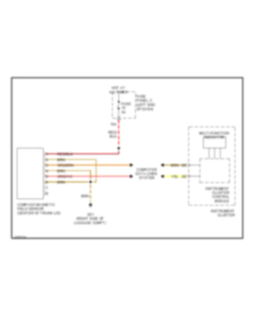
Electronic Compass Wiring Diagram for Volkswagen CC R-Line 2014
List of elements for Electronic Compass Wiring Diagram for Volkswagen CC R-Line 2014:
- 15a
- Compass magnetic field sensor (center of trunk lid)
- Computer data lines system
- Fuse 5a
- Fuse panel c (left end of dash)
- G51 (right side of luggage compt)
- Hot at all times
- Instrument cluster
- Instrument cluster control module
- Multi-function indicator
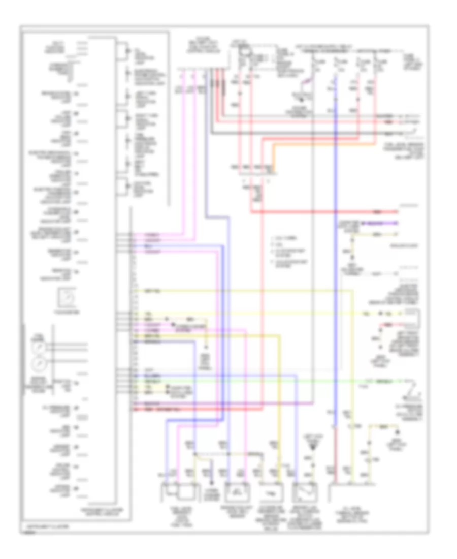
Instrument Cluster Wiring Diagram for Volkswagen CC R-Line 2014
List of elements for Instrument Cluster Wiring Diagram for Volkswagen CC R-Line 2014:
- (in fuel delivery unit) fuel pump (fp) control module
- (left kick panel) g639
- 2.0l turbo
- 3.6l
- 47a
- 48a
- Abs indicator lamp
- Air bag indicator lamp
- Analog clock
- Asr/esp indicator lamp
- Brake fluid level warning switch (in brake fluid master cylinder fluid reservoir)
- Brake system indicator lamp
- Computer data lines system
- Cruise control indicator lamp
- Electric parking/ handbrake malfunction indicator lamp
- Electro mechanical power steering indicator lamp
- Electro- mechanical parking brake control module (rear of center tunnel)
- Electronic power control malfunction indicator lamp
- Engine coolant level (ecl) sensor
- Engine coolant level/temperature (ecl/ect) indicator lamp
- Engine coolant temperature gauge
- Fuel gauge
- Fuel level sensor 2 (awd) (top of fuel tank)
- Fuel level sensor/ transfer fuel pump (in fuel delivery unit)
- Fuse 10a
- Fuse 11 fuse 17 5a
- Fuse 5a
- Fuse n/a
- Fuse panel b (on engine compt electronics box (high))
- Fuse panel c (left end of dash)
- G639 (left kick panel)
- G687 (on center tunnel)
- Generator indicator lamp
- High beam indicator lamp
- Hot at all times
- Instrument cluster
- Instrument cluster control module
- Lamp failure indicator lamp
- Left front brake pad wear sensor (on left front brake caliper assembly)
- Left turn signal indicator lamp
- Low fuel level indicator lamp
- Multi- function indicator
- Oil level indicator lamp
- Oil level thermal sensor (bottom of engine oil pan)
- Oil pressure indicator lamp
- Oil pressure switch (on oil filter assembly)
- Outside air temperature sensor (behind center of front grille)
- Position lamp ind
- Power distribution system
- Rear fog lamp indicator lamp
- Red
- Right turn signal indicator lamp
- Seat belt ind (if equipped)
- System
- T14a
- T14c
- T40
- T6e
- Tachometer
- Tire pressure monitoring display indicator lamp
- Trailer operation indicator lamp
- W/ stop/start
- W/o stop/start system
- Warning buzzer & tone
- Windshield washer fluid level indicator lamp
- Wiper/ washer system
- Wiper/washer system
INTERIOR LIGHTS
Courtesy Lamps Wiring Diagram (1 of 2) for Volkswagen CC R-Line 2014
List of elements for Courtesy Lamps Wiring Diagram (1 of 2) for Volkswagen CC R-Line 2014:
- (integral to driver's door lock assembly) driver's door lock unit
- (integral to front passenger door lock assembly) front passenger's door lock unit
- (on center front roof) g689
- (on left front side member) g684
- 44a
- Automatic dimming interior rearview mirror
- Computer data lines system
- Driver door warning lamp
- Driver's door contact switch
- Driver's door control module (in driver's door)
- Driver's entry lamp
- Driver's outside mirror
- Front interior lamp
- Front interior light
- Front passenger door warning lamp
- Front passenger's door contact switch
- Front passenger's door control module (in front passenger's door)
- Front passenger's entry lamp
- Front passenger's outside mirror
- Fuse 30a
- Fuse panel c (left end of dash)
- G638 (right kick panel)
- Glove compartment lamp switch
- Glove compartment light
- Hot at all times
- Interior monitoring deactivation switch
- Left center reading light
- Right center reading light
- T12i
- T16k
- T16l
- T20g
- T20h
- T28
- T28a
- T28b
- T28c
- T32a
- T32b
- T52b
- T52c
- Vehicle electrical system control module (under vehicle electrical system control module relay carrier)
Courtesy Lamps Wiring Diagram (2 of 2) for Volkswagen CC R-Line 2014
List of elements for Courtesy Lamps Wiring Diagram (2 of 2) for Volkswagen CC R-Line 2014:
- (behind right side of dash) comfort system central control module
- (if equipped) left footwell light
- (if equipped) right footwell light
- Computer data lines system
- Driver side rear door control module (in left rear door)
- Driver side rear door lock unit (integral to left rear door lock assembly)
- Driver vanity mirror light contact switch
- Driver's vanity mirror light
- Front passenger vanity mirror light contact switch
- Front passenger's vanity mirror light
- G42 (near steering column)
- G50 (left side of luggage compt)
- G689 (on center front roof)
- Garage door opener control head
- Left front sill panel ambient lighting fiber optic cable
- Left rear reading light
- Luggage compartment lamp switch
- Luggage compartment light
- Nca
- Rear courtesy light
- Rear interior light
- Rear lid lock unit (integral to rear lid lock assembly)
- Red
- Right front sill panel ambient lighting fiber optic cable
- Right rear door control module (in right rear door)
- Right rear door lock unit (integral to right rear door lock assembly)
- Right rear reading light
- T10e
- T18a
- T2e
- T2xi
- T2xj
- T6ao
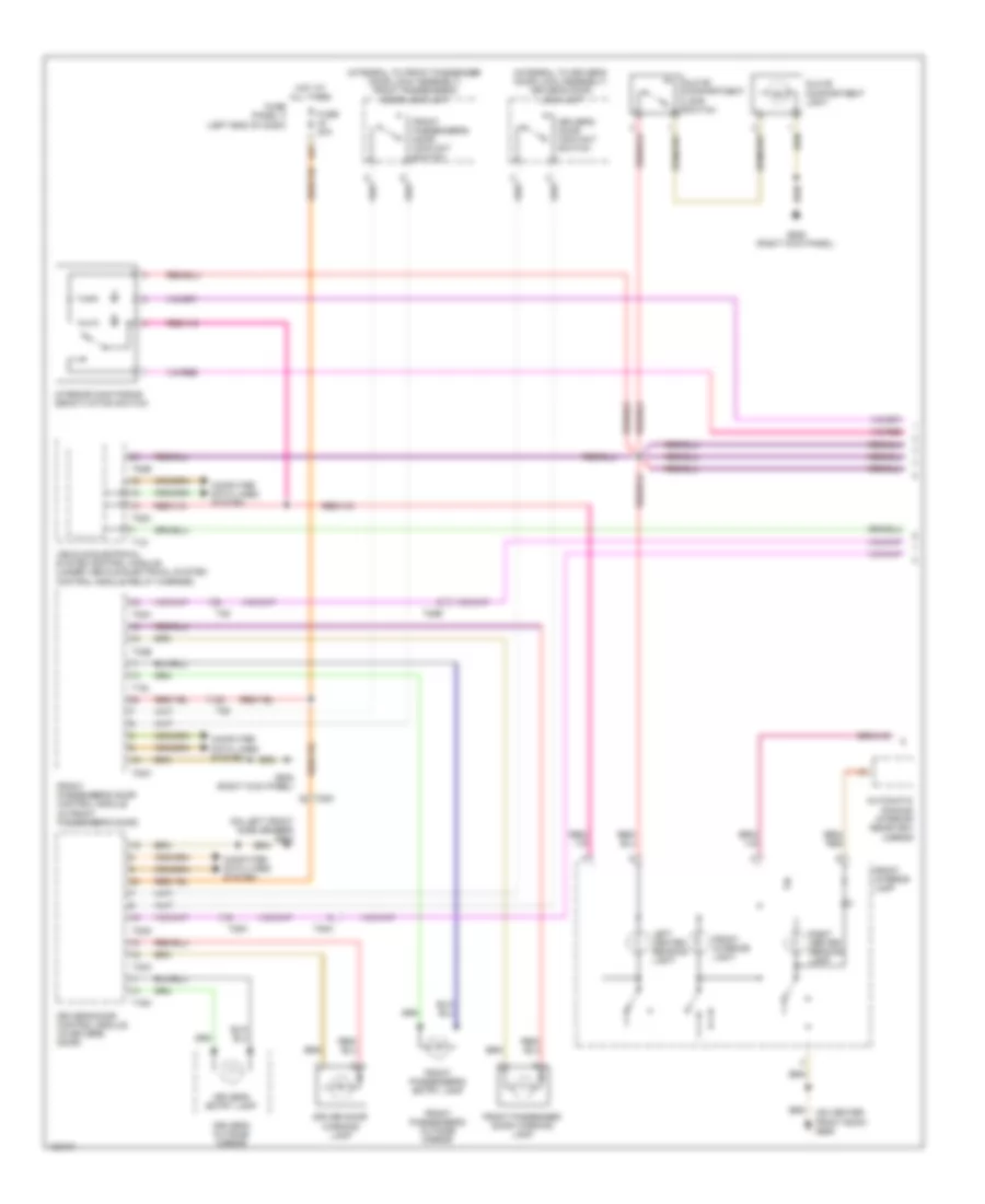
Instrument Illumination Wiring Diagram (1 of 2) for Volkswagen CC R-Line 2014
List of elements for Instrument Illumination Wiring Diagram (1 of 2) for Volkswagen CC R-Line 2014:
- (in left rear door) driver's side rear door control module
- (integral to left rear door lock assembly) driver's side rear door lock unit
- (w/ footwell lamp) driver's side rear door ambient lighting
- Auto hold switch (if equipped)
- Cd changer (if equipped)
- Center console switch module 2
- Computer data lines system
- Damping adjustment button
- Driver's side
- Driver's side rear interior locking button
- Electro- mechanical parking brake switch
- Electronic ignition switch
- Emergency call button
- Emergency flasher switch
- Engine terminal start control module
- Fuse 10a
- Fuse 30a
- Fuse panel c (left end of dash)
- G639 (left kick panel)
- G687 (on center tunnel)
- G689 (on center front roof)
- G77 (left lower "b" pillar)
- Hot at all times
- Instrument cluster
- Instrument panel & switch illumination dimmer switch
- Left rear heated seat regulating switch (if equipped)
- Light switch
- Nca
- Rear power window switch
- Right rear heated seat regulating switch (if equipped)
- Selector lever
- T10o
- T28a
- T52a
- T52b
- T52c
- Telephone base plate
- Tilt sunroof button 1
- Tiptronic switch (integral to selector lever park position lock switch)
- Vehicle electrical system control module (under vehicle electrical system control module relay carrier)
- W/ hid
- W/ navigation
- W/o hid
Instrument Illumination Wiring Diagram (2 of 2) for Volkswagen CC R-Line 2014
List of elements for Instrument Illumination Wiring Diagram (2 of 2) for Volkswagen CC R-Line 2014:
- (if equipped) right front interior lock switch
- (in right rear door) right rear door control module
- (integral to right rear door lock assembly) right rear door lock unit
- (on center tunnel) g687
- (w/ footwell lamp) front passenger door ambient lighting
- (w/ footwell lamp) right rear door ambient lighting
- Asr/ esp button
- Center instrument panel vent illumination bulb
- Cigarette lighter
- Computer data lines system
- Door locks system
- Driver door ambient lighting (w/ footwell lamp)
- Driver's door control module (in driver's door)
- Driver's door lock unit (integral to driver's door lock assembly)
- Driver's interior locking indicator lamp
- Driver's side power window switch
- Front interior lamp
- Front passenger's door control module (in front passenger's door)
- Front passenger's lock unit (integral to front passenger door lock assembly)
- G638 (right kick panel)
- G684 (on left front side member)
- G687 (on center tunnel)
- G689 (on center front of roof)
- G78 (right lower "b" pillar)
- Left instrument panel vent illumination bulb
- Mirror adjustment switch
- Rear lid remote release button & fuel filler door release button
- Right front power window switch
- Right instrument panel vent illumination bulb
- Right rear interior locking switch
- Right rear power window switch
- T12ac
- T20g
- T20h
- T28
- T28b
- T28c
- T32a
- T32b
MEMORY SYSTEMS
Memory Mirrors Wiring Diagram for Volkswagen CC R-Line 2014
List of elements for Memory Mirrors Wiring Diagram for Volkswagen CC R-Line 2014:
- 12a
- 44a
- Adj pos 1
- Adj pos 2
- Adj pos 3
- Adjustment motor
- Computer data lines system
- Defogger system
- Driver's memory settings control head (w/o massage) massage button (w/ massage)
- Driver's outside mirror
- Driver's seat adjustment control module
- Driver's side door control module (in driver's door)
- Entry
- Exterior lights system
- Fold-in motor
- Front passenger's door control module (in front passenger's door)
- Front passenger's outside mirror
- Fuse 10a
- Fuse 30a
- Fuse panel c (left end of dash)
- G638 (right kick panel)
- G684 (on left front side member)
- Heater
- Horizontal position sensor
- Hot at all times
- Interior lights system
- Memory button
- Mirror adjustment switch
- Mirror folding switch
- Mirror selector switch
- Mirrors system
- Nca
- Outside mirror heating switch
- Outside mirror switch
- Red
- T16k
- T16l
- T20g
- T20h
- T28
- T28c
- T32a
- T32f
- Turn
- Vertical position sensor
Memory Seat Wiring Diagram (1 of 2) for Volkswagen CC R-Line 2014
List of elements for Memory Seat Wiring Diagram (1 of 2) for Volkswagen CC R-Line 2014:
- 20a
- Adj pos 1
- Adj pos 2
- Adj pos 3
- Computer data lines system
- Driver power seat adjustment circuit breaker 1 (under left side of dash)
- Driver's memory settings control head (w/o massage) massage button (w/ massage)
- Driver's seat adjustment control module
- Driver's seat lumbar support height & fore/aft adjustment buttons
- Fore/aft
- G684 (on left front side member)
- Height adj
- Hot at all times
- Memory button
- T10ar
- T10c
- T12ab
- T16n
- T32f
Memory Seat Wiring Diagram (2 of 2) for Volkswagen CC R-Line 2014
List of elements for Memory Seat Wiring Diagram (2 of 2) for Volkswagen CC R-Line 2014:
- Angle adj
- Backrest adj
- Backrest adjustment motor/position sensor
- Driver's seat adjustment control head
- Fore/aft
- Height adj
- Lumbar support fore/aft adjustment motor/sensor (w/o massage) massage lumbar height sensor/pump (w/ massage)
- Lumbar support height adjustment motor/sensor
- Seat fore/ aft adjustment motor/position sensor
- Seat height adjustment motor/position sensor
- Seat tilt adjustment sensor/angle adjustment motor
- T4vm
NAVIGATION
Emergency Call Wiring Diagram for Volkswagen CC R-Line 2014
List of elements for Emergency Call Wiring Diagram for Volkswagen CC R-Line 2014:
- (or red)
- Computer data lines system
- Emergency call button
- Emergency call control & communication unit
- Fuse 15a
- Fuse 5a
- Fuse panel b (on engine compt electronics box)
- G683 (right front side member)
- Gps
- Gps system antenna
- Gsm
- Hot at all times
- Nca
- Radio/navigation display unit control module
- Red
- Roof antenna
- Sos
- Speech recognition system microphone
- T12l
- T40
- T52b
- Telephone antenna
- Telephone control head control module (under right front seat)
- Telephone microphone (in roof console)
- Vehicle electrical system control module (under vehicle electrical system control module relay carrier)
- Voltage stabilizer (w/ start/stop system)
- W/ speech recognition system
- W/ start/stop system
- W/o speech recognition system
- W/o start/stop system
Lane Change Assistance Wiring Diagram for Volkswagen CC R-Line 2014
List of elements for Lane Change Assistance Wiring Diagram for Volkswagen CC R-Line 2014:
- Computer data lines system
- Fuse 5a
- Fuse panel c (left end of dash)
- G51 (right side of luggage compt)
- Lane change assistance control module
- Lane change assistance control module 2
- Lane change assistance warning lamp in driver exterior rearview mirror
- Lane change assistance warning lamp in front passenger exterior rearview mirror
- T28
- T28c
Lane Departure Warning Wiring Diagram for Volkswagen CC R-Line 2014
List of elements for Lane Departure Warning Wiring Diagram for Volkswagen CC R-Line 2014:
- Computer data lines system
- Driver assistance front camera system
- Fuse 5a
- Fuse panel c (left end of dash)
- G639 (left kick panel)
- G689 (on center front roof)
- Window defogger for front sensor system
Navigation Wiring Diagram, with Amplifier (1 of 2) for Volkswagen CC R-Line 2014
List of elements for Navigation Wiring Diagram, with Amplifier (1 of 2) for Volkswagen CC R-Line 2014:
- (on vehicle electrical system control module relay carrier) rear window defogger relay
- (or nca)
- (under trim on left side of hatch) fm frequency filter in positive wire
- (under trim on left side of rear hatch) left antenna module
- (under trim on right side of hatch)
- (under trim on right side of rear hatch) right antenna module
- 32a
- Am/fm
- Antenna
- Cd changer (if equipped)
- Cellphone operating electronics control module (if equipped) (under right front seat)
- Computer data lines system
- Dab
- Digital radio antenna (if equipped)
- Emergency call module & communication unit
- External audio source connector (if equipped)
- External multimedia device interface
- Fm2
- Fuse 15a
- Fuse 30a
- Fuse panel b
- Fuse panel c (left end of dash)
- G610 (center console)
- Gps
- Gps antenna
- Gps/telephone antenna
- Hot at all times
- Interior lights system
- Nca
- Radio antenna 2
- Radio/navigation display unit control module
- Rear window defogger
- Speech recognition system microphone (if equipped)
- T12j
- T12l
- T12y
- T16c
- T40
- Telephone antenna
- Voltage stabilizer
- W/ emergency call system
- W/ multimedia socket
- W/ start/stop system
- W/o emergency call system
- W/o multimedia socket
- W/o start/stop system
Navigation Wiring Diagram, with Amplifier (2 of 2) for Volkswagen CC R-Line 2014
List of elements for Navigation Wiring Diagram, with Amplifier (2 of 2) for Volkswagen CC R-Line 2014:
- (pins 1 to 5: not used)
- Amplifier
- Bass
- Computer data lines system
- Fuse 30a
- Fuse panel b
- G610 (center console)
- Hot at all times
- Interior lights system
- Left front midrange speaker/ bass speaker
- Left front treble speaker
- Left rear bass speaker
- Left rear treble speaker
- Midrange
- Navigation system
- Nca
- Radio/navigation display unit control module
- Red
- Right front midrange speaker/ bass speaker
- Right front treble speaker
- Right rear bass speaker
- Right rear treble speaker
- T23
- T24
- T26g
- T28
- T28a
- T28b
- T28c
- T40
- Telephone base plate (w/ rns 315 radio navigation system) (in center armrest)
Navigation Wiring Diagram, without Amplifier (1 of 2) for Volkswagen CC R-Line 2014
List of elements for Navigation Wiring Diagram, without Amplifier (1 of 2) for Volkswagen CC R-Line 2014:
- (on vehicle electrical system control module relay carrier) rear window defogger relay
- (or nca)
- (under trim on left side of hatch) fm frequency filter in positive wire
- (under trim on left side of rear hatch) left antenna module
- (under trim on right side of rear hatch) right antenna module
- 32a
- Am/fm
- Antenna
- Cd changer (if equipped)
- Computer data lines system
- Dab
- Digital radio antenna (if equipped)
- Emergency call module & communication unit
- External audio source connector (if equipped)
- External multimedia device interface
- Fm2
- Fuse 15a
- Fuse 30a
- Fuse panel b
- Fuse panel c (left end of dash)
- G610 (center console)
- Gps
- Gps antenna
- Gps/telephone antenna
- Hot at all times
- Interior lights system
- Nca
- Radio antenna 2
- Radio/navigation display unit control module
- Rear window defogger
- Socket
- Speech recognition system microphone (if equipped)
- T12j
- T12l
- T12y
- T16c
- T40
- Telephone antenna
- Voltage stabilizer
- W/ emergency call system
- W/ multimedia
- W/ start/stop system
- W/o emergency call system
- W/o multimedia socket
- W/o start/stop system
Navigation Wiring Diagram, without Amplifier (2 of 2) for Volkswagen CC R-Line 2014
List of elements for Navigation Wiring Diagram, without Amplifier (2 of 2) for Volkswagen CC R-Line 2014:
- Cell phone operating electronics control module (if equipped) (under right front seat)
- G610 (center console)
- Interior lights system
- Left front bass speaker
- Left front treble speaker
- Left rear bass speaker
- Left rear treble speaker
- Navigation system
- Nca
- Radio/navigation display unit control module
- Red
- Right front bass speaker
- Right front treble speaker
- Right rear bass speaker
- Right rear treble speaker
- T26g
- T28
- T28a
- T28b
- T28c
- Telephone base plate (w/ rns 315 radio navigation system) (in center armrest)
Parking Assistant Wiring Diagram, with Parallel Parking for Volkswagen CC R-Line 2014
List of elements for Parking Assistant Wiring Diagram, with Parallel Parking for Volkswagen CC R-Line 2014:
- Center console switch module 2
- Computer data lines system
- Front parking aid warning buzzer (under left side of dash)
- Fuse 5a
- Fuse panel c (left end of dash)
- G42 (near steering column)
- G687 (on center tunnel)
- Instrument cluster
- Instrument cluster control module
- Interior lights system
- Left front center parking aid sensor (in left front side of radiator grill)
- Left front parallel parking assistance sensor (behind left front end of front bumper)
- Left front parking aid sensor (behind ends front bumper)
- Left rear center parking aid sensor (behind rear bumper)
- Left rear parallel parking assistance sensor
- Left rear parking aid sensor (behind rear bumper)
- Parallel parking assistance button
- Parallel parking assistance control module (behind left side of dash)
- Parallel parking assistance ind lamp
- Parking aid button
- Parking aid ind lamp
- Push button ill
- Rear parking aid warning buzzer (below right side of rear shelf)
- Right front center parking aid sensor (in right front side of radiator grill)
- Right front parallel parking assistance sensor (behind right front end of front bumper)
- Right front parking aid sensor (behind ends front bumper)
- Right rear center parking aid sensor (behind rear bumper)
- Right rear parallel parking assistance sensor
- Right rear parking aid sensor (behind rear bumper)
- T10av
- T12
- T12a
- T16
- T8a
Parking Assistant Wiring Diagram, without Parallel Parking for Volkswagen CC R-Line 2014
List of elements for Parking Assistant Wiring Diagram, without Parallel Parking for Volkswagen CC R-Line 2014:
- (near steering column) g42
- Center console switch module 2
- Computer data lines system
- Front parking aid warning buzzer (under left side of dash)
- Fuse 5a
- Fuse panel c (left end of dash)
- G687 (on center tunnel)
- Instrument cluster
- Instrument cluster control module
- Interior lights system
- Left front center parking aid sensor (in left front side of radiator grill)
- Left front parking aid sensor (behind ends front bumper)
- Left rear center parking aid sensor (behind rear bumper)
- Left rear parking aid sensor (behind rear bumper)
- Parking aid button
- Parking aid control module (left side of dash)
- Parking aid ind lamp
- Push button ill
- Rear parking aid warning buzzer (below right side of rear shelf)
- Right front center parking aid sensor (in right front side of radiator grill)
- Right front parking aid sensor (behind ends front bumper)
- Right rear center parking aid sensor (behind rear bumper)
- Right rear parking aid sensor (behind rear bumper)
- T12
- T12a
- T16
- T8a
- T8d
Rear View Camera Wiring Diagram for Volkswagen CC R-Line 2014
List of elements for Rear View Camera Wiring Diagram for Volkswagen CC R-Line 2014:
- 15a
- Computer data lines system
- Fuse 10a
- Fuse 15a
- Fuse 5a
- Fuse panel b (on engine compt electronics box)
- Fuse panel c (left end of dash)
- G51 (right side of luggage compt) g610 (center console)
- G610 (center console)
- Hot at all times
- Nca
- Radio/navigation display control module
- Rearview camera (in trunk lid pivoting emblem)
- Rearview camera system control module (right side of luggage compt)
- Reception
- Red
- T16c
- T1ai
- T1aj
- T26g
- T2ln
- T2xa
- T40
- Telephone base plate (w/ rns 315 radio navigation system) (in center armrest)
- Tv tuner (if equipped) (right side of luggage compt)
- W/ tv tuner
- W/o tv
Vehicle Positioning System Control Module Wiring Diagram for Volkswagen CC R-Line 2014
List of elements for Vehicle Positioning System Control Module Wiring Diagram for Volkswagen CC R-Line 2014:
- 10a
- 25a
- Diagnostic connector (under left side of dash)
- Fuse 10a
- Fuse 20a
- Fuse panel c (left end of dash)
- G50 (left side of luggage compt)
- Gps
- Gsm
- Hot at all times
- Nca
- T16
- T16r
- Vehicle gps antenna 1
- Vehicle gps antenna 2
- Vehicle positioning system control module
POWER DISTRIBUTION
Power Distribution Wiring Diagram (1 of 7) for Volkswagen CC R-Line 2014
List of elements for Power Distribution Wiring Diagram (1 of 7) for Volkswagen CC R-Line 2014:
- (left end of dash) fuse panel c
- (not used)
- 12a
- 13a
- 14a
- 15a
- 16a
- 2.0l turbo
- 22a
- 23a
- 24a
- 25a
- 26a
- 27a
- 28a
- 3.6l
- Abs control module
- Alarm horn relay
- Auxiliary engine coolant heater radio frequency receiver (if equipped)
- Battery
- Center console switch module 1
- Climatronic control module
- Comfort system central control module
- Compass magnetic field sensor
- Coolant fan control module
- Data link connector (dlc)
- Driver's door control module
- Electro- mechanical parking brake control module
- Electronic damping control module
- Electronic steering column lock control module
- Engine terminal start control module (w/ access/ start authorization)
- Engine terminal start control module (w/ access/start authorization)
- From battery (diagram 7 of 7)
- From fuse panel f (diagram 2 of 7)
- Front passe- nger's door control module
- Fuel pump control module
- Fuse
- Fuse 10a
- Fuse 150a
- Fuse 15a
- Fuse 20a
- Fuse 40a
- Fuse 50a
- Fuse 5a
- Fuse 60a
- Fuse 80a
- Fuse panel a (on engine compt electronics box (high & low))
- Fuse panel d (under right end of dash)
- Generator w/ voltage regulator
- Left rear door control module
- Light switch
- Nca
- Power steering control module
- Rain/ light recognition sensor
- Rear lid handle release switch (w/ rearview camera)
- Rear view camera system control module) (if equipped)
- Rear window defogger relay
- Red
- Right rear door control module
- Selector lever (w/ dsg transmission)
- Starter
- Suppress0r
- T10o
- T16r
- T18a
- T20c
- T20g
- T20h
- T28
- T28a
- T28b
- T28c
- T2fn
- T2ks
- T4i
- T52b
- Tiptronic switch
- Tire pressure monitoring control module (if equipped)
- To access/start authorization switch (diagram 6 of 7)
- To driver's power seat adjustment circuit breaker 1 (diagram 2 of 7)
- To fuse panel b (diagram 4 of 7)
- To fuse panel c (diagram 2 of 7)
- To fuse panel f (diagram 2 of 7)
- Towing recognition control module
- Vehicle electrical system control module
- Vehicle positioning system control module
- Windshield defroster relay
Power Distribution Wiring Diagram (2 of 7) for Volkswagen CC R-Line 2014
List of elements for Power Distribution Wiring Diagram (2 of 7) for Volkswagen CC R-Line 2014:
- (not used)
- 20a
- 29a
- 3 of 7)
- 3.6l
- 30a
- 31a
- 32a
- 33a
- 34a
- 35a
- 44a
- Air quality sensor
- Automatic dimming interior rear view mirror
- Battery (w/ recuperation)
- Battery interrupt igniter
- Battery monitoring control module
- Converter w/ socket 12v/230v
- Driver power seat adjustment circuit breaker 1 (under left side of dash)
- Driver's door control module
- Driver's seat adjustment control module (w/ memory)
- Driver's seat adjustment switch
- Driver's seat lumbar support adjustment switch
- Fresh air blower relay
- From battery (diagram 1 of 7)
- From fuse 4 (diagram o
- From fuse panel a (diagram 1 of 7)
- From fuse panel c (diagram 1 of 7)
- From fuse panel c (diagram 2 of 7)
- Front passenger's door control module
- Front passenger's seat adjustment switch
- Front passenger's seat lumbar support adjustment switch
- Front seat heating control module
- Fuse
- Fuse 10a
- Fuse 125a
- Fuse 15a
- Fuse 20a
- Fuse 25a
- Fuse 30a
- Fuse 5a
- Fuse 80a
- Fuse panel c (left end of dash)
- Fuse panel f (3.6l) (left rear of luggage compt)
- G687 (on center tunnel)
- Generator w/ voltage regulator (2.0l turbo)
- Headlamp washer relay (if equipped)
- High pressure sensor
- Inverter switch
- Left rear door control module
- Left rear heated seat regulating switch (if equipped)
- Oil level thermal sensor (3.6l & 2.0l turbo)
- Rear seat heating control module (if equipped)
- Rear window defogger relay
- Red
- Right rear door control module
- Right rear heated seat regulating switch (if equipped)
- Socket indicator lamp
- Sunroof control module
- T10c
- T10d
- T12ab
- T20g
- T20h
- T28
- T28a
- T28b
- T28c
- T4a
- T52a
- T52c
- T6dc
- T6dd
- T6e
- To converter w/ socket 12v/230v (diagram 2 of 7)
- To fuse panel b (diagram 4 of 7)
- To fuse panel c (diagram 1 of 7)
- To suppressor (diagram 1 of 7)
- Vehicle electrical system control module
- W/ recuperation
- W/ start/ stop system
- W/o start/ stop system
Power Distribution Wiring Diagram (3 of 7) for Volkswagen CC R-Line 2014
List of elements for Power Distribution Wiring Diagram (3 of 7) for Volkswagen CC R-Line 2014:
- 12v socket
- 21a
- 38a
- 39a
- 40a
- 41a
- 42a
- A/t
- Adaptive cruise control sensor
- Automatic transmission control module (tcm)
- Backup light switch
- Center console switch module 2
- Data link connector (dlc)
- Direct shift a/t
- Distance regulation control module
- Driver assistance front camera system
- Dsg transmission mechatronic
- Electronic damping control module
- Fresh air blower control module
- From fuse panel b (diagram 4 of 7)
- Fuse 10a
- Fuse 15a
- Fuse 20a
- Fuse 25a
- Fuse 40a
- Fuse 5a
- Fuse 5a 15a
- Fuse panel c (left end of dash)
- G51 (right side of luggage compt)
- G639 (left kick panel)
- Headlight range/ cornering lamp control module (w/ hid headlamps)
- Lane change assistance control module
- Lane change assistance control module 2
- Left front headlamp (w/ hid headlamps)
- Load reduction relay (on vehicle electrical system control module relay carrier)
- Multi- function transmission range (tr) switch
- Nca
- Parking aid control module (w/o parallel parking assistance) parallel parking assistance control module (w/ parallel parking assistance)
- Positive crankshaft ventilation heating element (3.6l)
- Rear window shade control module
- Rear window shade switch
- Seat ventilation switch
- Seat ventilation switch 2
- Selector lever
- T100
- T10a
- T10c
- T10d
- T10f
- T14a
- T16
- T20m
- T52b
- To fuse 1 (diagram 2 of 7)
- To fuse 2 (diagram 5 of 7)
- To fuse panel c (diagram 5 of 7)
- To rear cigarette lighter (diagram 6 of 7)
- Towing recognition control module
- Vehicle electrical system control module
- W/ dsg transmission
Power Distribution Wiring Diagram (4 of 7) for Volkswagen CC R-Line 2014
List of elements for Power Distribution Wiring Diagram (4 of 7) for Volkswagen CC R-Line 2014:
- 2.0l turbo
- 3.6l
- A/t
- Auxiliary heater control module (if equipped)
- Battery monitoring control module (w/ recuperation)
- Coolant circulation pump relay (3.6l)
- Data bus on board diagnostic interface
- Direct shift a/t
- Dsg transmission mechatronic (direct shift a/t)
- Dual tone horn relay
- Engine control module (ecm) (3.6l)
- From fuse 26 (diagram 4 of 7)
- From fuse 26 u (diagram 4 of 7)
- From fuse panel a (diagram 1 of 7)
- From fuse panel f (diagram 2 of 7)
- Fuse 1 fuse 6 5a 15a
- Fuse 20a
- Fuse 25 40a
- Fuse 25a
- Fuse 29 50a
- Fuse 40a
- Fuse 50a
- Fuse 5a
- Fuse panel b (on engine compt electronics box (high))
- Instrument cluster
- Instrument cluster control module
- Nca
- Red
- T20m
- T26a
- T2cn
- T40
- T52a
- T52c
- T94
- To fuse 15 (diagram 4 of 7)
- To fuse 17 (diagram 4 of 7)
- To load reduction relay (diagram 3 of 7)
- Towing recognition control module
- Transmission control module (tcm) (a/t)
- Vehicle electrical system control module
- W/ recuperation
- W/o start/ stop system
Power Distribution Wiring Diagram (5 of 7) for Volkswagen CC R-Line 2014
List of elements for Power Distribution Wiring Diagram (5 of 7) for Volkswagen CC R-Line 2014:
- (2.0l turbo)
- (3.6l)
- (left end of dash) fuse panel c
- (not used)
- (on engine compartment electronics box (high)) fuse panel b
- 10a
- Abs control module
- Air bag control module
- All-wheel drive control module (if equipped)
- Asr/esp button
- Center console switch module 1
- Data bus on board diagnostic interface
- Electro- mechanical parking brake control module
- Engine control module (2.0l turbo)
- Engine control module (ecm)
- Engine control module (ecm) (2.0l turbo)
- From fuse 11 v (diagram 4 of 7)
- From fuse panel c (diagram 3 of 7)
- From r fuse 5 (diagram 3 of 7)
- Front passenger's air bag disabled indicator lamp (if equipped)
- Fuel pump (fp) control module
- Fuse 10a
- Fuse 22 30a
- Fuse 27 60a
- Fuse 30a
- Fuse 5a
- Fuse 9 5a
- Fuse n/a
- Instrument cluster
- Instrument cluster module
- Light switch
- Mass air flow (maf) sensor
- Passenger occupant detection system control module
- Power steering control module
- Right front headlamp (w/ hid headlamps)
- Steering column electronic systems control module
- T10b
- T10o
- T16o
- T3dt
- T40
- T6e
- T8z
- T94
- Tiptronic switch
- To fuse 8 (diagram 6 of 7)
- To voltage stablizer (diagram 7 of 7)
- Vehicle positioning system control module
- Windshield defroster relay
- Wiper motor control module
Power Distribution Wiring Diagram (6 of 7) for Volkswagen CC R-Line 2014
List of elements for Power Distribution Wiring Diagram (6 of 7) for Volkswagen CC R-Line 2014:
- Access/start authorization switch
- Amplifier (if equipped)
- Analog clock
- Cellphone operating electronics control module (w/o telephone control head) telephone control head module (w/ telephone control head)
- Center console switch module 1
- Cigarette lighter
- Electronic ignition switch
- Electronic steering column lock control module
- Engine control module (2.0l turbo)
- Engine terminal start control module
- From fuse 9 (diagram 5 of 7)
- From fuse panel c (diagram 3 of 7)
- From fuse panel c g (diagram 1 of 7)
- Fuel pump relay 2 (2.0l turbo)
- Fuse 15a
- Fuse 30a
- Fuse 5a
- Fuse panel b (on engine compartment electronics box (high))
- G639 (left kick panel)
- G687 (on center tunnel)
- Ignition switch key lock solenoid (w/ tiptronic)
- Interior lights system
- Radio
- Radio/navigation display control module
- Rear cigarette lighter
- Red
- Start system button
- Steering column electronics systems control module
- T160
- T16c
- T23
- T40
- T52c
- T94
- To voltage stablizer (diagram 7 of 7)
- Tv tuner
- Vehicle electrical system control module
- W/ access/start authorization
- W/ navigation
- W/ start/stop system
- W/o access/start authorization
- W/o navigation
- W/o start/stop system
Power Distribution Wiring Diagram (7 of 7) for Volkswagen CC R-Line 2014
List of elements for Power Distribution Wiring Diagram (7 of 7) for Volkswagen CC R-Line 2014:
- (diagram 6 of 7)
- (not used)
- 18a
- 2.0l turbo
- 3.6l
- 47a
- 48a
- Analog clock
- Battery (w/ recuperation)
- Cell phone operating electronics control module (w/o telephone control head) telephone control head module (w/ telephone control head)
- Emergency call control module & communication unit
- Engine control module
- From fuse panel b y
- From fuse panel c (diagram 5 of 7)
- From fuse panel c z (diagram 5 of 7)
- Fuse 10a
- Fuse 7.5a
- Fuse n/a
- Fuse panel c (left end of dash)
- Instrument cluster
- Instrument cluster control module
- Radio/ navigation display control module (w/ navigation) radio (w/o navigation)
- Red
- Starter (w/ start/ stop system)
- Starter (w/o start/ stop system)
- T16c
- T52c
- T94
- To fuse panel a (diagram 1 of 7)
- Tv tuner
- Vehicle electrical system control module
- Voltage stabilizer (w/ start/stop system)
POWER DOOR LOCKS
Power Door Locks Wiring Diagram (1 of 3) for Volkswagen CC R-Line 2014
List of elements for Power Door Locks Wiring Diagram (1 of 3) for Volkswagen CC R-Line 2014:
- (if equipped)
- (integral to driver's door lock assembly) driver's central door lock unit
- 12a
- 28a
- Bulb
- Central locking safe indicator lamp
- Child safety lock activate indicator lamp
- Child safety lock button
- Computer data lines system
- Driver door ambient lighting bulb (w/ footwell lamp)
- Driver door control module (in driver's door)
- Driver interior locking button
- Driver interior locking indicator lamp
- Driver's side power window switch
- Driver's side rear interior locking button
- Front passenger door control module (in front passenger's door)
- Front passenger interior locking indicator lamp
- Front passenger's central door lock unit (integral to front passenger's door lock assembly)
- Front passenger's interior locking button
- Fuse 10a
- Fuse 30a
- Fuse panel c (left end of dash)
- G638 (right kick panel)
- G684 (on left front side member)
- G77 (left lower "b" pillar)
- Hot at all times
- Illumination push button
- Interior lights system
- Left rear central door lock unit (integral to left rear door lock assembly)
- Left rear door control module (in left rear door)
- Left rear interior locking indicator lamp
- Power windows & mirrors systems
- Power windows system
- Push button illumination bulb
- Rear lid remote & fuel filler door release button
- Rear lid remote lock key switch
- T20g
- T20h
- T28
- T28a
- T28c
- T32a
- T32b
Power Door Locks Wiring Diagram (2 of 3) for Volkswagen CC R-Line 2014
List of elements for Power Door Locks Wiring Diagram (2 of 3) for Volkswagen CC R-Line 2014:
- (in front passenger's outside door handle) front passenger's outside door handle touch sensor, central locking button & access/ start authorization antenna
- (in left rear outside door handle) left rear outside door handle touch sensor & central locking button
- (in right front wheelwell) alarm horn
- (in right rear outside door handle) right rear outside door handle touch sensor & central locking button
- (left kick panel) g639
- (not used)
- (on relay carrier 2) alarm horn relay
- (right lower "b" pillar) g78
- (w/ footwell lamp) front passenger door ambient lighting bulb
- 14a
- 16a
- 2.0l
- 3.6l
- 35a
- Access/start authorization switch
- Antenna
- Anti-theft immobilizer reading module
- Computer data lines system
- Electronic ignition switch
- Electronic steering column lock control module (near base of steering column)
- Engine control module (in center of plenum)
- Fuel filler door unlock motor
- Fuse 10a
- Fuse 30a
- Fuse panel c (left end of dash)
- G51 (right side of luggage compt)
- G638 (right kick panel)
- G639 (left kick panel)
- G77 (left lower "b" pillar)
- G78 (right lower "b" pillar)
- Hot at all times
- Ignition switch key lock solenoid (w/ tiptronic)
- Interior lights system
- Push button illumination bulb
- Right rear central door lock unit (integral to right rear door lock assembly)
- Right rear door control module (in right rear door)
- Right rear interior locking button
- Right rear interior locking indicator lamp
- Sensor
- Steering column electronic systems control module (top of steering column)
- Steering column lock actuator
- System power windows
- T16o
- T28
- T28a
- T28b
- T94
- W/ stop/start system
- W/o stop/start system
Power Door Locks Wiring Diagram (3 of 3) for Volkswagen CC R-Line 2014
List of elements for Power Door Locks Wiring Diagram (3 of 3) for Volkswagen CC R-Line 2014:
- Antenna
- Anti-lock brakes system
- Central locking & anti-theft alarm system antenna (in "a" pillar)
- Comfort system central control module (behind right side of dash)
- Computer data lines system
- Driver access/start system antenna, exterior door handle central locking button & exterior door handle touch sensor (in driver's outside door handle)
- Driver's reading light button
- Engine hood contact switch
- Fuse 15a
- G50 (left side of luggage compt)
- G638 (right kick panel)
- G684 (on left front side member)
- G685 (on right front long member)
- Hot at all times
- Interior access/start authorization antenna 1 (under center, front of rear seat)
- Interior access/start authorization antenna 2 (under rear of center console)
- Interior access/start authorization antenna 3 (below right side of rear shelf)
- Interior lights system
- Interior monitoring deactivation switch
- Interior monitoring off indicator lamp
- Left backup lamp bulb
- Left instrument panel
- Luggage compartment access/start authorization antenna (center front of luggage compt)
- Luggage compartment light
- Luggage compartment light switch (integral to rear lid lock assembly)
- Nca
- Push button illumination bulb
- Rear bumper access/start authorization antenna (behind rear bumper)
- Rear lid central locking system motor
- Rear lid handle release switch
- Rear lid handle release switch & emblem motor
- Rear lid lock unit
- Sensor
- T12kf
- T18a
- T18c
- T28
- T28a
- T28b
- T28c
- T2e
- T2f
- T2ks
- T4uy
- T52a
- T52b
- T52c
- T6an
- T6ao
- T8r
- Vehicle electrical system control module (under vehicle electrical system control module relay carrier)
- W/ rearview camera
- W/o rearview camera
POWER MIRRORS
Automatic Day/Night Mirror Wiring Diagram for Volkswagen CC R-Line 2014
List of elements for Automatic Day/Night Mirror Wiring Diagram for Volkswagen CC R-Line 2014:
- 12a
- 44a
- Automatic dimming interior rearview mirror
- Computer data lines system
- Driver's outside mirror
- Driver's side door control module (in driver's door)
- Exterior lights system
- Front interior lamp
- Front passenger's door control module (in front passenger's door)
- Front passenger's outside mirror
- Fuse 10a
- Fuse 30a
- Fuse panel c (left end of dash)
- G638 (right kick panel)
- G684 (on left front side member)
- G689 (on center front roof)
- Hot at all times
- T16k
- T16l
- T20g
- T20h
- T28
- T28c
- T52c
- Vehicle electrical system control module (under vehicle electrical system control module relay carrier)
Power Mirrors Wiring Diagram for Volkswagen CC R-Line 2014
List of elements for Power Mirrors Wiring Diagram for Volkswagen CC R-Line 2014:
- 12a
- 44a
- Adjustment motor
- Automatic day/night mirror circuit
- Computer data lines system
- Defogger system
- Driver's outside mirror
- Driver's side door control module (in driver's door)
- Entry
- Exterior lights system
- Fold-in motor
- Front passenger's door control module (in front passenger's door)
- Front passenger's outside mirror
- Fuse 10a
- Fuse 30a
- Fuse panel c (left end of dash)
- G638 (right kick panel)
- G684 (on left front side member)
- Heater
- Horizontal position sensor
- Hot at all times
- Interior lights system
- Mirror adjustment switch
- Mirror folding switch
- Mirror selector switch
- Nca
- Outside mirror heating switch
- Outside mirror switch
- Red
- T16k
- T16l
- T20g
- T20h
- T28
- T28c
- T32a
- Turn
- Vertical position sensor
POWER SEATS
Driver Power Seat Wiring Diagram for Volkswagen CC R-Line 2014
List of elements for Driver Power Seat Wiring Diagram for Volkswagen CC R-Line 2014:
- 20a
- Angle adjustment button
- Backrest adjustment button
- Driver power seat adjustment circuit breaker 1 (under left side of dash)
- Driver's backrest adjustment motor
- Driver's seat adjustment switch
- Driver's seat forward/ back adjustment motor
- Driver's seat height adjustment motor
- Driver's seat lumbar support adjustment switch
- Driver's seat lumbar support curvature adjustment motor
- Driver's seat lumbar support height adjustment motor
- G684 (on left front side member)
- Hot at all times
- Seat angle adjustment motor
- Seat forward/back adjustment button
- Seat height adjustment button
- T10al
- T10c
- T4rj
- T6dc
Driver Seat Ventilation Wiring Diagram for Volkswagen CC R-Line 2014
List of elements for Driver Seat Ventilation Wiring Diagram for Volkswagen CC R-Line 2014:
- (on left front side member) g684
- 21a
- Driver seat backrest blower fan
- Driver seat cushion blower fan
- Fuse 10a
- Fuse panel c (left end of dash)
- G684 (left front side member)
- Indicator lamp
- Seat ventilation switch
- T10c
- T4vo
- T4vp
Heated Seats Wiring Diagram (1 of 2) for Volkswagen CC R-Line 2014
List of elements for Heated Seats Wiring Diagram (1 of 2) for Volkswagen CC R-Line 2014:
- (on left front side member) g684
- (on right front side member) g683
- Climatronic control module (integral to climatronic control head)
- Driver's backrest heating element
- Driver's heated seat temperature sensor/ seat heating element
- Front seat heating control module (under driver's seat)
- Fuse 10a
- Fuse 25a
- Fuse panel c (left end of dash)
- G684 (on left front side member)
- G687 (on center tunnel)
- Hot at all times
- Interior lights system
- Left rear heated seat regulating switch (if equipped)
- Left seat heating button
- Rear seat heating control module (if equipped) (under right front seat)
- Right rear heated seat regulating switch (if equipped)
- Right seat heating button
- T10c
- T20c
- T52b
- Vehicle electrical system control module (under vehicle electrical system control module relay carrier)
Heated Seats Wiring Diagram (2 of 2) for Volkswagen CC R-Line 2014
List of elements for Heated Seats Wiring Diagram (2 of 2) for Volkswagen CC R-Line 2014:
- Front passenger's backrest heating element
- Front passenger's heated seat temperature sensor/seat heating element
- G683 (right front side member)
- G78 (right lower "b" pillar)
- Left rear backrest heating element & seat backrest temperature sensor
- Left rear heated seat temperature sensor & bench seat heating element
- Red
- Right rear heated seat temperature sensor & bench seat heating element
- Right rear seat backrest temperature sensor & seat backrest heating element
- T10c
- T10d
Passenger Power Seat Wiring Diagram for Volkswagen CC R-Line 2014
List of elements for Passenger Power Seat Wiring Diagram for Volkswagen CC R-Line 2014:
- 20a
- Angle adjustment button
- Backrest adjustment button
- Driver power seat adjustment circuit breaker 1 (under left side of dash)
- Front passenger's backrest adjustment motor
- Front passenger's seat adjustment switch
- Front passenger's seat angle adjustment motor
- Front passenger's seat forward/back adjustment motor
- Front passenger's seat height adjustment motor
- Front passenger's seat lumbar support adjustment switch
- Front passenger's seat lumbar support curvature adjustment motor
- Front passenger's seat lumbar support height adjustment motor
- G683 (right front side member)
- Hot at all times
- Seat forward/back adjustment button
- Seat height adjustment button
- T10as
- T10d
- T4afi
- T4vl
- T6dd
Passenger Seat Ventilation Wiring Diagram for Volkswagen CC R-Line 2014
List of elements for Passenger Seat Ventilation Wiring Diagram for Volkswagen CC R-Line 2014:
- (right front side member) g683
- 21a
- Front passenger seat backrest blower fan
- Front passenger seat cushion blower fan
- Fuse 10a
- Fuse panel c (left end of dash)
- G683 (right front side member)
- Indicator lamp
- Seat ventilation switch 2
- T10d
- T4vq
- T4vr
POWER TOP/SUNROOF
Power Top/Sunroof Wiring Diagram for Volkswagen CC R-Line 2014
List of elements for Power Top/Sunroof Wiring Diagram for Volkswagen CC R-Line 2014:
- 30a
- Computer data lines system
- Fuse 20a
- Fuse panel c (left end of dash)
- G689 (on center front roof)
- Hot at all times
- Interior lights system
- Red
- Sunroof control module (forward of sunroof)
- Sunroof tilt button 1
- Tilt sunroof motor
POWER WINDOWS
Power Windows Wiring Diagram for Volkswagen CC R-Line 2014
List of elements for Power Windows Wiring Diagram for Volkswagen CC R-Line 2014:
- (left lower "b" pillar) g77
- (on left front side member)
- (on left front side member) g684
- 12a
- 35a
- 44a
- Child safety lock
- Child safety lock-activated indicator lamp
- Computer data lines system
- Door locks system
- Driver window lowering micro switch
- Driver's side door control module (in driver's door)
- Driver's side power window switch
- Front passenger window lowering micro switch
- Front passenger's door control module (in front passenger's door)
- Fuse 10a
- Fuse 30a
- Fuse panel c (left end of dash)
- G638 (right kick panel)
- G684
- G78 (right lower "b" pillar)
- Hot at all times
- Interior lights system
- Left front power window switch
- Left rear door control module (in left rear door)
- Left rear power window switch
- Left rear power window switch & push button illumination bulb
- Left rear window lowering micro switch
- Push button illumination bulb
- Red
- Right front power window switch
- Right front power window switch & push button illumination bulb
- Right rear door control module (in right rear door)
- Right rear power window switch
- Right rear power window switch & push button illumination bulb
- Right rear window lowering micro switch
- T20g
- T20h
- T20k
- T20l
- T28
- T28a
- T28b
- T28c
- T32a
- T32b
- Window regulator motor
Rear Window Sun Shade Wiring Diagram for Volkswagen CC R-Line 2014
List of elements for Rear Window Sun Shade Wiring Diagram for Volkswagen CC R-Line 2014:
- (left side of luggage compt) g50
- Center console switch module 2
- Computer data lines system
- Fuse 10a
- Fuse 5a
- Fuse panel c (left end of dash)
- G687 (on center tunnel)
- Rear sun shade motor
- Rear window shade control module
- Rear window shade switch illumination bulb
- T52b
- T52c
- Vehicle electrical system control module (under vehicle electrical system control module relay carrier)
RADIO
Multimedia Interface Wiring Diagram for Volkswagen CC R-Line 2014
List of elements for Multimedia Interface Wiring Diagram for Volkswagen CC R-Line 2014:
- Computer data lines system
- External audio source connector
- External multimedia device interface
- Fuse 15a
- Fuse panel b
- G610 (center console)
- Hot at all times
- Media in
- Radio/navigation display control module
- T12j
- T12y
- T16c
- T30a
- T40
- Voltage stabilizer
- W/ start/stop system
- W/o start/stop system
Radio Wiring Diagram, with Navigation with Amplifier (1 of 2) for Volkswagen CC R-Line 2014
List of elements for Radio Wiring Diagram, with Navigation with Amplifier (1 of 2) for Volkswagen CC R-Line 2014:
- (on vehicle electrical system control module relay carrier) rear window defogger relay
- (or nca)
- (under trim on left side of hatch) fm frequency filter in positive wire
- (under trim on left side of rear hatch) left antenna module
- (under trim on right side of hatch)
- (under trim on right side of rear hatch) right antenna module
- 32a
- Am/fm
- Antenna
- Cd changer (if equipped)
- Cellphone operating electronics control module (if equipped) (under right front seat)
- Computer data lines system
- Dab
- Digital radio antenna (if equipped)
- Emergency call module & communication unit
- External audio source connector (if equipped)
- External multimedia device interface
- Fm2
- Fuse 15a
- Fuse 30a
- Fuse panel b
- Fuse panel c (left end of dash)
- G610 (center console)
- Gps
- Gps antenna
- Gps/telephone antenna
- Hot at all times
- Interior lights system
- Nca
- Radio antenna 2
- Radio/navigation display unit control module
- Rear window defogger
- Speech recognition system microphone (if equipped)
- T12j
- T12l
- T12y
- T16c
- T40
- Telephone antenna
- Voltage stabilizer
- W/ emergency call system
- W/ multimedia socket
- W/ start/stop system
- W/o emergency call system
- W/o multimedia socket
- W/o start/stop system
Radio Wiring Diagram, with Navigation with Amplifier (2 of 2) for Volkswagen CC R-Line 2014
List of elements for Radio Wiring Diagram, with Navigation with Amplifier (2 of 2) for Volkswagen CC R-Line 2014:
- (pins 1 to 5: not used)
- Amplifier
- Bass
- Computer data lines system
- Fuse 30a
- Fuse panel b
- G610 (center console)
- Hot at all times
- Interior lights system
- Left front midrange speaker/ bass speaker
- Left front treble speaker
- Left rear bass speaker
- Left rear treble speaker
- Midrange
- Navigation system
- Nca
- Radio/navigation display unit control module
- Red
- Right front midrange speaker/ bass speaker
- Right front treble speaker
- Right rear bass speaker
- Right rear treble speaker
- T23
- T24
- T26g
- T28
- T28a
- T28b
- T28c
- T40
- Telephone base plate (w/ rns 315 radio navigation system) (in center armrest)
Radio Wiring Diagram, with Navigation without Amplifier (1 of 2) for Volkswagen CC R-Line 2014
List of elements for Radio Wiring Diagram, with Navigation without Amplifier (1 of 2) for Volkswagen CC R-Line 2014:
- (on vehicle electrical system control module relay carrier) rear window defogger relay
- (or nca)
- (under trim on left side of hatch) fm frequency filter in positive wire
- (under trim on left side of rear hatch) left antenna module
- (under trim on right side of rear hatch) right antenna module
- 32a
- Am/fm
- Antenna
- Cd changer (if equipped)
- Computer data lines system
- Dab
- Digital radio antenna (if equipped)
- Emergency call module & communication unit
- External audio source connector (if equipped)
- External multimedia device interface
- Fm2
- Fuse 15a
- Fuse 30a
- Fuse panel b
- Fuse panel c (left end of dash)
- G610 (center console)
- Gps
- Gps antenna
- Gps/telephone antenna
- Hot at all times
- Interior lights system
- Nca
- Radio antenna 2
- Radio/navigation display unit control module
- Rear window defogger
- Socket
- Speech recognition system microphone (if equipped)
- T12j
- T12l
- T12y
- T16c
- T40
- Telephone antenna
- Voltage stabilizer
- W/ emergency call system
- W/ multimedia
- W/ start/stop system
- W/o emergency call system
- W/o multimedia socket
- W/o start/stop system
Radio Wiring Diagram, with Navigation without Amplifier (2 of 2) for Volkswagen CC R-Line 2014
List of elements for Radio Wiring Diagram, with Navigation without Amplifier (2 of 2) for Volkswagen CC R-Line 2014:
- Cell phone operating electronics control module (if equipped) (under right front seat)
- G610 (center console)
- Interior lights system
- Left front bass speaker
- Left front treble speaker
- Left rear bass speaker
- Left rear treble speaker
- Navigation system
- Nca
- Radio/navigation display unit control module
- Red
- Right front bass speaker
- Right front treble speaker
- Right rear bass speaker
- Right rear treble speaker
- T26g
- T28
- T28a
- T28b
- T28c
- Telephone base plate (w/ rns 315 radio navigation system) (in center armrest)
Radio Wiring Diagram, without Navigation with Amplifier (1 of 2) for Volkswagen CC R-Line 2014
List of elements for Radio Wiring Diagram, without Navigation with Amplifier (1 of 2) for Volkswagen CC R-Line 2014:
- (or nca)
- (under trim on left side of hatch) fm frequency filter in positive wire
- (under trim on left side of rear hatch) left antenna module
- (under trim on right side of rear hatch) right antenna module
- 32a
- Am/fm
- Antenna
- Cd changer (if equipped)
- Cellphone operating electronics control module (if equipped) (under right front seat)
- Computer data lines system
- Dab
- Digital radio antenna (if equipped)
- Emergency call module & communication unit
- External audio source connector (if equipped)
- External multimedia device interface
- Fm2
- Fuse 15a
- Fuse 30a
- Fuse panel b
- Fuse panel c (left end of dash)
- G610 (center console)
- Hot at all times
- Interior lights system
- Nca
- Radio
- Radio antenna 2
- Rear window defogger
- Rear window defogger relay (on vehicle electrical system control module relay carrier)
- Socket
- Speech recognition system microphone (if equipped)
- T12j
- T12l
- T12y
- T16c
- T40
- Voltage stabilizer
- W/ emergency call system
- W/ multimedia
- W/ start/stop system
- W/o emergency call system
- W/o multimedia socket
- W/o start/stop system
Radio Wiring Diagram, without Navigation with Amplifier (2 of 2) for Volkswagen CC R-Line 2014
List of elements for Radio Wiring Diagram, without Navigation with Amplifier (2 of 2) for Volkswagen CC R-Line 2014:
- Amplifier
- Bass
- Computer data lines system
- Fuse 30a
- Fuse panel b
- G610 (center console)
- Hot at all times
- Left front midrange speaker/ bass speaker
- Left front treble speaker
- Left rear bass speaker
- Left rear treble speaker
- Midrange
- Red
- Right front midrange speaker/ bass speaker
- Right front treble speaker
- Right rear bass speaker
- Right rear treble speaker
- T23
- T24
- T28
- T28a
- T28b
- T28c
- T40
Radio Wiring Diagram, without Navigation without Amplifier (1 of 2) for Volkswagen CC R-Line 2014
List of elements for Radio Wiring Diagram, without Navigation without Amplifier (1 of 2) for Volkswagen CC R-Line 2014:
- (on vehicle electrical system control module relay carrier) rear window defogger relay
- (under trim on left side of hatch) fm frequency filter in positive wire
- 32a
- Am/fm
- Antenna
- Cd changer (if equipped)
- Cell phone operating electronics control module (under right front seat)
- Computer data lines system
- Dab
- Digital radio antenna (if equipped)
- Emergency call module & communication unit
- External audio source connection
- External multimedia device interface
- Fm2
- Fuse 30a
- Fuse panel c (left end of dash)
- G610 (center console)
- Hot at all times
- Nca
- Radio
- Radio antenna 2
- Rear window defogger
- Speech recognition system microphone (if equipped)
- T12j
- T12l
- T12y
- T16c
- T52b
- Vehicle electrical system control module (under vehicle electrical system control module relay carrier)
- W/ emergency call system
- W/ multimedia socket
- W/o emergency call system
- W/o multimedia socket
- W/o start/stop system
Radio Wiring Diagram, without Navigation without Amplifier (2 of 2) for Volkswagen CC R-Line 2014
List of elements for Radio Wiring Diagram, without Navigation without Amplifier (2 of 2) for Volkswagen CC R-Line 2014:
- (under trim on left side of rear hatch) left antenna module
- (under trim on right side of rear hatch) right antenna module
- Am/fm
- Dab
- Fm2
- Fuse 15a
- Fuse panel b
- Hot at all times
- Left front bass speaker
- Left front treble speaker
- Left rear bass speaker
- Left rear treble speaker
- Nca
- Red
- Right front bass speaker
- Right front treble speaker
- Right rear bass speaker
- Right rear treble speaker
- T28
- T28a
- T28b
- T28c
- T40
- Voltage stabilizer
- W/ start/stop system
- W/o start/stop system
SHIFT INTERLOCK
Electronic Parking Brake Wiring Diagram for Volkswagen CC R-Line 2014
List of elements for Electronic Parking Brake Wiring Diagram for Volkswagen CC R-Line 2014:
- 10a
- 13a
- 2.0l
- 22a
- 24a
- 3.6l
- Anti-lock brakes system
- Brake light switch (on brake master cylinder)
- Brake system indicator lamp
- Center console switch module 1
- Clutch position sensor (top of clutch assembly)
- Computer data lines system
- Electric parking/
- Electro-mechanical parking brake control module (rear of center tunnel)
- Fuse 20 fuse 8 5a
- Fuse 20a
- Fuse 5a
- Fuse panel b (on engine compt electronics box (high))
- Fuse panel c (left end of dash)
- G639 (left kick panel)
- G687 (on center tunnel)
- G688 (on center tunnel)
- Hand brake malfunction indicator lamp
- Hot at all times
- Instrument cluster
- Instrument cluster control module
- Interior lights system
- Left parking brake motor (on left rear brake caliper)
- Longitudinal acceleration sensor
- M/t
- Parking light ind
- Red
- Right parking brake motor (on right rear brake caliper)
- Rotation rate sensor
- T40
- T52b
- T52c
- Transverse acceleration sensor
- Vehicle electrical system control module (under electrical system control module relay carrier)
Shift Interlock Wiring Diagram, with Direct Shift for Volkswagen CC R-Line 2014
List of elements for Shift Interlock Wiring Diagram, with Direct Shift for Volkswagen CC R-Line 2014:
- (under vehicle electrical system control module relay carrier) vehicle electrical system control module
- 13a
- 39a
- Brake light switch (on brake master cylinder)
- Computer data lines system
- Dsg transmission mechatronic
- Electronic ignition switch
- Fuse 20 5a
- Fuse 20a
- Fuse 5a
- Fuse panel b (on engine compt electronics box (high))
- Fuse panel c (left end of dash)
- G639 (left kick panel)
- G687 (on center tunnel)
- Hot at all times
- Ignition switch keylock solenoid
- Interior lights system
- Nca
- Red
- Selector lever
- Selector lever park position lock switch
- Shift lock solenoid (on shifter assembly)
- Steering column electronic system control module (top of steering column)
- T10o
- T16o
- T20m
- T2hy
- T40
- T52b
- T52c
- Transmission range (tr) display
Shift Interlock Wiring Diagram, without Direct Shift for Volkswagen CC R-Line 2014
List of elements for Shift Interlock Wiring Diagram, without Direct Shift for Volkswagen CC R-Line 2014:
- (in center of plenum) (3.6l) engine control module
- (on top of transmission) multi-function transmission range switch
- 10a
- 13a
- 2.0l
- 3.6l
- 39a
- Brake light switch (on brake master cylinder)
- Computer data lines system
- Electronic ignition switch
- Fuse 10a
- Fuse 20 fuse 8 5a
- Fuse 20a
- Fuse 5a
- Fuse panel b (on engine compt electronics box (high))
- Fuse panel c (left end of dash)
- G639 (left kick panel)
- G673 (left long member)
- G687 (on center tunnel)
- Hot at all times
- Ignition switch key lock solenoid
- Interior lights system
- Nca
- Selector lever park position lock switch
- Shift lock solenoid
- Steering column electronic systems control module (top of steering column)
- T16o
- T40
- T52b
- T52c
- T94
- Tiptronic switch (integral to selector lever park position lock switch)
- Transmission control module (in left front wheelwell)
- Transmission range (tr) display
- Vehicle electrical system control module (under vehicle electrical system control module relay carrier)
STARTING/CHARGING
2.0L TURBO
2.0L Turbo, Charging Wiring Diagram for Volkswagen CC R-Line 2014
List of elements for 2.0L Turbo, Charging Wiring Diagram for Volkswagen CC R-Line 2014:
- (on engine compartment electronics box (high) fuse panel b
- (or nca)
- (under vehicle electrical system control module relay carrier) vehicle electrical system control module
- Battery
- Battery monitoring control module (w/ recuperation)
- Computer data lines system
- Engine control module (in center of plenum)
- Fuse 150a
- Fuse 5a
- Fuse panel a (on engine compartment electronics box (high & low))
- G12 (left side of engine compt)
- Generator indicator lamp
- Generator w/ voltage regulator
- Instrument cluster
- Instrument cluster control module
- Nca
- Red
- Starter
- T40
- T4a
- T52a
- T52c
- T94
- W/ recuperation
- W/o recuperation
2.0L Turbo, Starting Wiring Diagram, with Access/Start Authorization for Volkswagen CC R-Line 2014
List of elements for 2.0L Turbo, Starting Wiring Diagram, with Access/Start Authorization for Volkswagen CC R-Line 2014:
- (left kick panel)
- (left kick panel) g639
- (not used)
- 10a
- 16a
- Access/start authorization switch
- All times
- Anti-theft immobilizer reader module
- Anti-theft system
- Battery
- Center console switch module 1
- Charging circuit
- Computer data lines system
- Electronic ignition switch
- Electronic steering column lock control module (near base of steering column)
- Engine control module (in center of plenum)
- Fuse 10a
- Fuse 30 50a
- Fuse 5a
- Fuse 9 5a
- Fuse panel b (on engine compartment electronics box (high))
- Fuse panel c (left end of dash)
- G12 (left side of engine compt)
- G639
- G639 (left kick panel)
- G687 (on center tunnel)
- Hot at
- Hot at all times
- Ignition switch key lock solenoid (w/ tiptronic)
- Power distribution system
- Push button illumination
- Red
- Start system button
- Starter
- Steering column electronic systems control module (top of steering column)
- T16o
- T40
- T52b
- T52c
- T94
- Terminal & engine start control system control module
- Vehicle electrical system control module (under vehicle electrical system control module relay carrier)
2.0L Turbo, Starting Wiring Diagram, without Access/Start Authorization for Volkswagen CC R-Line 2014
List of elements for 2.0L Turbo, Starting Wiring Diagram, without Access/Start Authorization for Volkswagen CC R-Line 2014:
- (not used)
- 10a
- 16a
- Access/start authorization switch
- All times
- Anti-theft immobilizer reader module
- Anti-theft system
- Battery
- Charging circuit
- Computer data lines system
- Electronic ignition switch
- Electronic steering column lock control module (near base of steering column)
- Engine control module (in center of plenum)
- Fuse 10a
- Fuse 30 50a
- Fuse 5a
- Fuse 9 5a
- Fuse panel b (on engine compartment electronics box (high))
- Fuse panel c (left end of dash)
- G12 (left side of engine compt)
- G639 (left kick panel)
- Hot at
- Ignition switch key lock solenoid (w/ tiptronic)
- Interior lights system
- Power distribution system
- Push button ill
- Red
- Starter
- Steering column electronic systems control module (top of steering column)
- T16o
- T40
- T52a
- T52b
- T52c
- T94
- Vehicle electrical system control module (under vehicle electrical system control module relay carrier)
- W/ start/stop system
- W/o start/stop system
3.6L
3.6L, Charging Wiring Diagram for Volkswagen CC R-Line 2014
List of elements for 3.6L, Charging Wiring Diagram for Volkswagen CC R-Line 2014:
- (left side of luggage compt)
- (on engine compartment electronics box (high & low)) fuse panel b
- (under vehicle electrical system control module relay carrier) vehicle electrical system control module
- Battery (w/ recuperation)
- Battery (w/o recuperation)
- Battery interrupt igniter
- Battery monitoring control module (w/ recuperation)
- Computer data lines system
- Fuse 150a
- Fuse panel f (left rear of luggage compt)
- G12 (left side of engine compt)
- G676
- G676 (left side of luggage compt)
- Generator indicator lamp
- Generator w/ voltage regulator
- Instrument cluster
- Instrument cluster control module
- Nca
- Power distribution system
- Red
- Starter
- Suppressor
- T4a
- T52a
- T52c
3.6L, Starting Wiring Diagram, with Access/Start Authorization (1 of 2) for Volkswagen CC R-Line 2014
List of elements for 3.6L, Starting Wiring Diagram, with Access/Start Authorization (1 of 2) for Volkswagen CC R-Line 2014:
- 10a
- Center console switch module 1
- Computer data lines system
- Fuse 10a
- Fuse 9 5a
- Fuse panel b (on engine compartment electronics box (high))
- Fuse panel c (left end of dash)
- G639 (left kick panel)
- G687 (on center tunnel)
- Hot at all times
- Push button illumination bulb
- Red
- Start system button
- Steering column electronic systems control module (top of steering column)
- T16o
- T40
- T52b
- T52c
- Terminal & engine start control system control module
- Vehicle electrical system control module (under vehicle electrical system control module relay carrier)
3.6L, Starting Wiring Diagram, with Access/Start Authorization (2 of 2) for Volkswagen CC R-Line 2014
List of elements for 3.6L, Starting Wiring Diagram, with Access/Start Authorization (2 of 2) for Volkswagen CC R-Line 2014:
- (not used)
- 16a
- Access/start authorization switch
- All times
- Anti-theft immobilizer reader module
- Anti-theft system
- Battery
- Battery interrupt igniter
- Charging circuit
- Electronic ignition switch
- Electronic steering column lock control module (near base of steering column)
- Engine control module (in center of plenum)
- Fuse 5a
- Fuse panel c (left end of dash)
- Fuse panel f (left rear of luggage compt)
- G676 (left side of luggage compt)
- Hot at
- Ignition switch keylock solenoid (w/ tiptronic)
- Interior lights system
- Power distribution system
- Push button illumination bulb
- Red
- Starter
- T94
3.6L, Starting Wiring Diagram, without Access/Start Authorization for Volkswagen CC R-Line 2014
List of elements for 3.6L, Starting Wiring Diagram, without Access/Start Authorization for Volkswagen CC R-Line 2014:
- (not used)
- 10a
- 16a
- Access/start authorization switch
- Anti-theft immobilizer reader module
- Anti-theft system
- Battery
- Battery interrupt igniter
- Charging circuit
- Computer data lines system
- D1 red
- Electronic ignition switch
- Electronic steering column lock control module (near base of steering column)
- Engine control module (in center of plenum)
- Fuse 10a
- Fuse 5a
- Fuse 9 5a
- Fuse panel b (on engine compartment electronics box (high))
- Fuse panel c (left end of dash)
- Fuse panel f (left rear of luggage compt)
- G639 (left kick panel)
- G676 (left side of luggage compt)
- Hot at all times
- Ignition switch keylock solenoid (w/ tiptronic)
- Interior lights system
- Power distribution system
- Push button illumination bulb
- Red
- Starter
- Steering column electronic systems control module (top of steering column)
- T16o
- T40
- T52a
- T52c
- T94
- Vehicle electrical system control module (under vehicle electrical system control module relay carrier)
- W/ start/stop system
- W/o start/stop system
SUPPLEMENTAL RESTRAINTS
Supplemental Restraints Wiring Diagram, with Rear Side Air Bag (1 of 3) for Volkswagen CC R-Line 2014
List of elements for Supplemental Restraints Wiring Diagram, with Rear Side Air Bag (1 of 3) for Volkswagen CC R-Line 2014:
- Air bag control module (under front of center console)
- Air bag ind
- Computer data lines system
- Driver's head curtain air bag igniter
- Front passenger seat occupant sensor
- Front passenger's air bag deactivation key switch (if equipped)
- Front passenger's air bag disabled indicator lamp (if equipped)
- Front passenger's air bag igniters (behind right side of dash)
- Front passenger's head curtain air bag igniter
- Fuse 10a
- Fuse panel c (left end of dash)
- Igniter 1 (usa)
- Igniter 2 (usa)
- Instrument cluster
- Instrument cluster control module
- Nca
- Passenger side rear seat belt tensioner igniter (if equipped)
- Seat belt ind
- T3a
- T3bx
- W/ seat occupied sensor
- W/o seat occupied sensor
Supplemental Restraints Wiring Diagram, with Rear Side Air Bag (2 of 3) for Volkswagen CC R-Line 2014
List of elements for Supplemental Restraints Wiring Diagram, with Rear Side Air Bag (2 of 3) for Volkswagen CC R-Line 2014:
- (usa) passenger occupant detection system pressure sensor
- (usa) passenger occupant detection system seat belt force sensor & front passenger seat belt switch
- Driver side rear air bag igniter (w/ rear side air bag)
- Driver's seat belt switch
- Driver's side rear seat belt tensioner igniter (if equipped)
- Driver's thorax air bag igniter
- Front passenger seat belt switch
- Front passenger's thorax air bag igniter
- Nca
- Passenger occupant detection system control module (usa) (under front passenger's seat)
- Passenger side rear thorax air bag igniter (w/ rear side air bag)
- Red
- T10b
- T3a
- T3bx
Supplemental Restraints Wiring Diagram, with Rear Side Air Bag (3 of 3) for Volkswagen CC R-Line 2014
List of elements for Supplemental Restraints Wiring Diagram, with Rear Side Air Bag (3 of 3) for Volkswagen CC R-Line 2014:
- (in steering wheel) driver air bag igniter
- (in steering wheel) driver air bag igniter 2
- Air bag control module (under front of center console)
- Air bag spiral spring/return spring (w/ slip ring)
- Battery
- Battery interrupt igniter
- Computer data lines system
- Driver side air bag crash sensor (in driver front door)
- Driver's front air bag crash sensor (usa) (left front of engine compt)
- Driver's seat belt tensioner igniter 1 (base of driver's "b" pillar)
- Driver's side rear side air bag crash sensor (base of driver's "c" pillar)
- Front passenger side air bag crash sensor (in passenger front door)
- Front passenger's seat belt tensioner igniter 1 (base of front passenger "b" pillar)
- Nca
- Passenger side front air bag crash sensor (usa) (right front of engine compt)
- Passenger's side rear side air bag crash sensor (base of passenger "c" pillar)
- Red
- State solid
- Steering column electronic systems control module (top of steering column)
- T28
- T28c
- T4ae
- Wiring connector
Supplemental Restraints Wiring Diagram, without Rear Side Air Bag (1 of 2) for Volkswagen CC R-Line 2014
List of elements for Supplemental Restraints Wiring Diagram, without Rear Side Air Bag (1 of 2) for Volkswagen CC R-Line 2014:
- Air bag control module (under front of center console)
- Air bag ind
- Computer data lines system
- Driver's head curtain air bag igniter
- Driver's thorax air bag igniter
- Front passenger air bag igniter 1 (behind right side of dash)
- Front passenger's air bag deactivation key switch (if equipped)
- Front passenger's air bag disabled indicator lamp (if equipped)
- Front passenger's head curtain air bag igniter
- Front passenger's thorax air bag igniter
- Fuse 10a
- Fuse panel c (left end of dash)
- Instrument cluster
- Instrument cluster control module
- Nca
- Seat belt ind
- T3b
- T3c
Supplemental Restraints Wiring Diagram, without Rear Side Air Bag (2 of 2) for Volkswagen CC R-Line 2014
List of elements for Supplemental Restraints Wiring Diagram, without Rear Side Air Bag (2 of 2) for Volkswagen CC R-Line 2014:
- (in steering wheel) driver air bag igniter
- (in steering wheel) driver's air bag igniter 2
- Air bag control module (under front of center console)
- Air bag spiral spring/return spring w/ slip ring
- Computer data lines system
- Driver side air bag crash sensor (in driver front door)
- Driver's seat belt switch
- Driver's seat belt tensioner igniter 1 (base of driver's "b" pillar)
- Driver's side rear side air bag crash sensor (base of driver's "c" pillar)
- Front passenger side air bag crash sensor (in front passenger front door)
- Front passenger's seat belt switch
- Front passenger's seat belt tensioner igniter 1 (base of front passenger "b" pillar)
- Front passenger's seat occupied sensor
- Nca
- Passenger's side rear side air bag crash sensor (base of passenger "c" pillar)
- Red
- State solid
- Steering column electronic systems control module (top of steering column)
- T28
- T28c
- T4ae
TRANSMISSION
A/T Wiring Diagram (1 of 2) for Volkswagen CC R-Line 2014
List of elements for A/T Wiring Diagram (1 of 2) for Volkswagen CC R-Line 2014:
- (left long member) g673
- 10a
- 13a
- 39a
- Computer data lines system
- Fuse 10a
- Fuse 15a
- Fuse 5a
- Fuse panel b (on engine compt electronics box)
- Fuse panel c (left end of dash)
- G687 (on center tunnel)
- Hot at all times
- Interior lights system
- Nca
- Selector lever park position lock switch
- Shift lock solenoid
- Solenoid valves
- Steering column electronic systems control module (top of steering column)
- T160
- T40
- Tiptronic switch (integral to selector lever park position lock switch)
- Transmission
- Transmission control module (tcm)
- Transmission fluid temperature sensor/transmission input speed sensor & transmission output speed sensor (transmission fluid temperature sensor: in transmission) (transmission input & output speed sensor: in transmission, above valve body assembly)
- Transmission range (tr) display
A/T Wiring Diagram (2 of 2) for Volkswagen CC R-Line 2014
List of elements for A/T Wiring Diagram (2 of 2) for Volkswagen CC R-Line 2014:
- (on top of transmission) multi-function transmission range (tr) switch
- Air bag spiral spring/return w/ slip ring
- Cluster
- Cluster control
- Computer
- Computer data lines system
- Data lines
- Engine control module (in center of plenum)
- G673 (left long member)
- Instrument
- Left multi- function buttons
- Module
- Multi-function indicator
- Multi-function steering wheel control module
- Nca
- Right multi-function buttons
- Steering column electronic system control module (top of steering column)
- System
- T16o
- T3bj
- T3ci
- T6aw
- T6de
- T8v
- T8w
- T94
- Tiptronic downshift button (if equipped)
- Tiptronic upshift button (if equipped)
AWD Wiring Diagram for Volkswagen CC R-Line 2014
List of elements for AWD Wiring Diagram for Volkswagen CC R-Line 2014:
- (on brake master cylinder) brake light switch
- 2.0l turbo
- 3.6l
- All-wheel drive control module (on rear differential)
- Computer data lines system
- Engine control module (ecm) (in center of plenum)
- Fuse 10a
- Fuse panel c (left end of dash)
- G77 (left lower "b" pillar)
- Haldex clutch control valve
- Nca
- Oil pressure/ temperature sensor
- T2hz
- T52c
- T8z
- T94
- Vehicle electrical system control module (under vehicle electrical system control module relay carrier)
Direct Shift A/T Wiring Diagram (1 of 2) for Volkswagen CC R-Line 2014
List of elements for Direct Shift A/T Wiring Diagram (1 of 2) for Volkswagen CC R-Line 2014:
- (top of steering column)
- Air bag spiral spring/return w/ slip ring
- Automatic transmission hydraulic pressure sensors
- Automatic transmission pressure regulating valves
- Clutch oil temperature sensor/ transmission input speed (rpm) sensor (clutch oil temperature sensor: in transmission, near multi-plate clutch) (transmission input speed (rpm) sensor: in transmission above valve body assembly)
- Computer data lines system
- Control module
- Drive shaft 1 speed sensor
- Drive shaft 2 speed sensor
- Dsg transmission mechatronic (in direct shift gearbox)
- Electronic system
- Engine control module (in center of plenum)
- Fuse 15a
- Fuse panel b (on engine compt electronics box)
- G673 (left long member)
- Gear position distance sensors
- Hot at all times
- Instrument cluster
- Instrument cluster control module
- Left multifunction buttons
- Multi-function indicator
- Multi-function steering wheel control module
- Nca
- Right multi-function buttons
- Solenoid valves
- Steering column
- T16o
- T20m
- T3bj
- T3ci
- T40
- T4ah
- T6aw
- T6de
- T8v
- T8w
- T94
- Temperature sensor (control module)
- Tiptronic downshift button (if equipped)
- Tiptronic upshift button (if equipped)
- Transmission fluid temperature sensor
- Transmission output speed (rpm) sensor
Direct Shift A/T Wiring Diagram (2 of 2) for Volkswagen CC R-Line 2014
List of elements for Direct Shift A/T Wiring Diagram (2 of 2) for Volkswagen CC R-Line 2014:
- (under vehicle electrical system control module relay carrier) vehicle electrical system control module
- 13a
- 20a
- 39a
- Brake light switch (on brake master cylinder)
- Computer data lines system
- Electronic ignition switch
- Engine controls system
- Fuse 10a
- Fuse 15a
- Fuse 5a
- Fuse panel c (left end of dash)
- G639 (left kick panel)
- G687 (on center tunnel)
- Hot at all times
- Ignition switch keylock solenoid
- Interior lights system
- Nca
- Red
- Selector lever
- Selector lever park position lock switch
- Shift lock solenoid (on shifter assembly)
- Steering column electronic system control module (top of steering column)
- T10o
- T16o
- T2hy
- T52b
- T52c
- Transmission range (tr) display
TRUNK, TAILGATE, FUEL DOOR
Trunk & Fuel Door Release Wiring Diagram for Volkswagen CC R-Line 2014
List of elements for Trunk & Fuel Door Release Wiring Diagram for Volkswagen CC R-Line 2014:
- 12a
- 28a
- 44a
- Comfort system central control module (behind right side of dash)
- Computer data lines system
- Driver's side door control module (in driver's door)
- Emblem motor
- Fuel filler door unlock motor
- Fuse
- Fuse 10a
- Fuse 30a
- Fuse panel sc (left end of dash)
- G50 (left side of luggage compt)
- G51 (right side of luggage compt)
- G638 (right kick panel)
- G684 (on left front side member)
- Hot at all times
- Instrument cluster
- Instrument cluster control module
- Interior lights system
- Left backup lamp bulb
- Power rear lid opener sensor/rear lid opener sensor 2
- Rear lid handle release switch
- Rear lid lock unit (integral to rear lid lock assembly)
- Rear lid opener control module
- Rear lid remote lock key switch
- Rear lid remote release button/ fuel filler door release button
- T18a
- T18d
- T20g
- T28c
- T2e
- T2f
- T2kf
- T2ks
- T32a
- T4hk
- T4hl
- T52a
- T5hk
- T8r
- Vehicle electrical system control module (under vehicle electrical system control module relay carrier)
- W/ rear view camera
- W/o rear view camera
WARNING SYSTEMS
Buzzer Wiring Diagram for Volkswagen CC R-Line 2014
List of elements for Buzzer Wiring Diagram for Volkswagen CC R-Line 2014:
- 2.0l turbo
- 3.6l
- Air bag control module (under front of center console)
- Brake fluid level warning switch (in brake fluid master cylinder fluid reservoir)
- Brake system indicator light
- Computer data lines system
- Data bus on board diagnostic interface (under left side of dash)
- Driver's door central locking lock unit (integral to driver's door lock assembly)
- Driver's door contact switch
- Driver's seat belt switch
- Driver's side door control module (in driver's door)
- Front passenger's door central locking lock unit (integral to passenger's door lock assembly)
- Front passenger's door contact switch
- Front passenger's door control module (in front passenger's door)
- Front passenger's seat belt switch
- Fuse 17 fuse 11
- Fuse 5a
- Fuse panel b (on engine compartment electronics box (high))
- Fuse panel c (left end of dash)
- G639 (left kick panel)
- Hot at all times
- Instrument cluster
- Instrument cluster control module
- Left front brake pad wear sensor (on left front brake caliper assembly)
- Multi-function indicator
- Nca
- Power distribution system
- Red
- Seat belt indicator lamp
- T20g
- T20h
- T40
- Warning buzzer & tone
Tire Pressure Monitoring Wiring Diagram for Volkswagen CC R-Line 2014
List of elements for Tire Pressure Monitoring Wiring Diagram for Volkswagen CC R-Line 2014:
- 15a
- Abs control module (on right side of firewall)
- Computer data lines system
- Fuse 5a
- Fuse panel c (left end of dash)
- G51 (right side of luggage compt)
- G687 (on center tunnel)
- Hot at all times
- Instrument cluster
- Instrument cluster control module
- Interior lights system
- Left front tire pressure monitoring sensor (in left front wheel assembly)
- Left rear tire pressure monitoring sensor (in left rear wheel assembly)
- Right front tire pressure monitoring sensor (in right front wheel assembly)
- Right rear tire pressure monitoring sensor (in right rear wheel assembly)
- Tire pressure monitoring control module (integral to comfort system central control module)
- Tire pressure monitoring display button
- Tire pressure monitoring display indicator lamp
WIPER/WASHER
Wiper/Washer Wiring Diagram for Volkswagen CC R-Line 2014
List of elements for Wiper/Washer Wiring Diagram for Volkswagen CC R-Line 2014:
- 15a
- 33a
- Computer data lines system
- Fuse 30a
- Fuse 5a
- Fuse panel b (on engine compartment electronics box (high))
- Fuse panel c (left end of dash)
- G646 (firewall)
- G647 (firewall)
- G685 (on right front long member)
- G689 (on center front roof)
- Headlamp washer pump (if equipped)
- Headlamp washer relay (if equipped) (on vehicle electrical system control module relay carrier)
- Hot at all times
- Instrument cluster
- Instrument cluster control module
- Instrument cluster system
- Left washer nozzle heater (if equipped)
- Multifunction indicator selection switch
- Nca
- Rain/light recognition sensor (in interior rearview mirror retainer)
- Rear window wiper switch
- Right washer nozzle heater (if equipped)
- Steering column combination switch
- Steering column electronic systems control module (top of steering column)
- T16o
- T40
- T52a
- T52b
- T52c
- Trip computer reset button
- Vehicle electrical system control module (under vehicle electrical system control module relay carrier)
- Windshield & headlamp washer pump switch
- Windshield washer fluid level ind lamp
- Windshield washer fluid level sensor (in windshield washer fluid reservoir)
- Windshield washer pump
- Windshield washer pump relay
- Windshield wiper intermittent mode switch
- Windshield wiper intermittent regulator
- Windshield wiper motor
- Wiper motor control module

 Čeština
 Dansk
Dansk Deutsch
 Ελληνικά
 English
 English
 Español
 Suomi
Suomi Français
 עברית
עברית Hrvatski
 Magyar
 Italiano
 日本語
日本語 한국어
한국어 Nederlands
 Polski
 Português
 Português
 Română
 Русский
 Slovenčina
 Slovenščina
 Svenska
 Türkçe
 中文 (中国)