
 Čeština
 Dansk
Dansk Deutsch
 Ελληνικά
 English
 English
 Español
 Suomi
Suomi Français
 עברית
עברית Hrvatski
 Magyar
 Italiano
 日本語
日本語 한국어
한국어 Nederlands
 Polski
 Português
 Português
 Română
 Русский
 Slovenčina
 Slovenščina
 Svenska
 Türkçe
 中文 (中国)

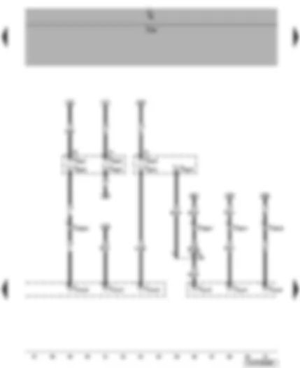
Wiring Diagram VW TRANSPORTER 2008 - Fuses - terminal 75 voltage supply relay 1 - hand-held two-way radio interface

, special signal system, accident data memory . Wiring diagrams, Pin Connector, Location")
| A1 | Second battery |
| D | Ignition/starter switch |
| J519 | Onboard supply control unit |
| J680 | Terminal 75 voltage supply relay 1 |
| S315 | Special vehicle fuse 25 |
| S316 | Special vehicle fuse 26 |
| S317 | Special vehicle fuse 27 |
| S318 | Special vehicle fuse 28 |
| S319 | Special vehicle fuse 29 |
| S320 | Special vehicle fuse 30 |
| T2bk | 2-pin connector, black, hand-held two-way radio interface, under front passenger seat |
| 366 | Earth connection 1, in main wiring harness |
| 387 | Earth connection 22, in main wiring harness |
| B173 | Positive connection 2 (X), in interior wiring harness |
| B252 | Positive connection (30, police), in interior wiring harness |
| B256 | Positive connection (75x, police), in interior wiring harness |
| B313 | Positive connection 17 (30), in main wiring harness |
| B314 | Positive connection 18 (30), in main wiring harness |
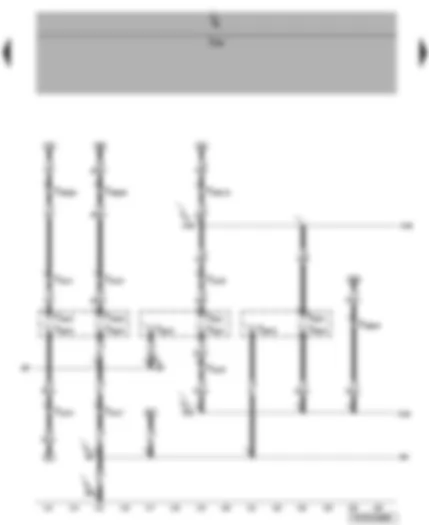
Wiring Diagram VW TRANSPORTER 2008 - Fuses - socket on table interface - front socket interface

| J519 | Onboard supply control unit |
| S306 | Special vehicle fuse 16 |
| S307 | Special vehicle fuse 17 |
| S308 | Special vehicle fuse 18 |
| S309 | Special vehicle fuse 19 |
| S310 | Special vehicle fuse 20 |
| S311 | Special vehicle fuse 21 |
| S312 | Special vehicle fuse 22 |
| S313 | Special vehicle fuse 23 |
| S314 | Special vehicle fuse 24 |
| T2bh | 2-pin connector, black, socket on table interface, on lower part of left C-pillar |
| T2bj | 2-pin connector, black, front socket interface, in centre dash panel |
| T10br | 10-pin connector, blue, coupling station under driver seat |
| B252 | Positive connection (30, police), in interior wiring harness |
| B313 | Positive connection 17 (30), in main wiring harness |
| B314 | Positive connection 18 (30), in main wiring harness |
Wiring Diagram VW TRANSPORTER 2008 - Special signals interface - rotating light relay

| J326 | Rotating light relay |
| J519 | Onboard supply control unit |
| T10bp | 10-pin connector, green, coupling station under driver seat |
| T10bq | 10-pin connector, orange, coupling station under driver seat |
| T17e | 17-pin connector, black, special signals interface, under roof, near left B-pillar |
| 454 | Earth connection 4, in optional equipment wiring harness |
Wiring Diagram VW TRANSPORTER 2008 - Special signals interface

| J519 | Onboard supply control unit |
| SB35 | Fuse 35 on fuse holder B |
| T10bp | 10-pin connector, green, coupling station under driver seat |
| T10bq | 10-pin connector, orange, coupling station under driver seat |
| T10br | 10-pin connector, blue, coupling station under driver seat |
| T17e | 17-pin connector, black, special signals interface, under roof, near left B-pillar |
| B340 | Connection 1 (58d), in main wiring harness |
| B341 | Connection 2 (58d), in main wiring harness |
| B342 | Connection 3 (58d), in main wiring harness |
Wiring Diagram VW TRANSPORTER 2008 - Special signals interface - third rotating light interface - front 'stop' command light interface
| J519 | Onboard supply control unit |
| T3ao | 3-pin connector, black, third rotating light interface, under roof, near left D-pillar |
| T4aq | 4-pin connector, black, front 'stop' command light interface, on air filter |
| T10bp | 10-pin connector, green, coupling station under driver seat |
| T10br | 10-pin connector, blue, coupling station under driver seat |
| T12w | 12-pin connector, black, special signals interface, under roof, near left B-pillar |
| T17e | 17-pin connector, black, special signals interface, under roof, near left B-pillar |
| X78 | Connection 1, in optional equipment wiring harness |
Wiring Diagram VW TRANSPORTER 2008 - Special signals interface - loudspeaker and front LED speed camera interface

| J519 | Onboard supply control unit |
| T8ah | 8-pin connector, black, loudspeaker/ front LED speed camera interface, on air filter |
| T10bq | 10-pin connector, orange, coupling station under driver seat |
| T10br | 10-pin connector, blue, coupling station under driver seat |
| T12w | 12-pin connector, black, special signals interface, under roof, near left B-pillar |
Wiring Diagram VW TRANSPORTER 2008 - Special signals interface - loudspeaker and front LED speed camera interface - warning lamps interface - rear wiper warning lamp interface

| E34 | Rear wiper switch |
| J519 | Onboard supply control unit |
| T2bl | 2-pin connector, black, rear wiper warning lamp interface |
| T6cd | 6-pin connector, black, warning lamps interface |
| T8ah | 8-pin connector, black, loudspeaker/ front LED speed camera interface, on air filter |
| T10bp | 10-pin connector, green, coupling station under driver seat |
| T12w | 12-pin connector, black, special signals interface, under roof, near left B-pillar |
| T41 | 41-pin connector |
| B183 | Connection 1 (washer pump), in interior wiring harness |
| X79 | Connection 2, in optional equipment wiring harness |
Wiring Diagram VW TRANSPORTER 2008 - Flashing lights relay - flashing lights relay 2 - rear LED speed camera interface

| J519 | Onboard supply control unit |
| J630 | Flashing lights relay |
| J890 | Flashing lights relay 2 |
| T4ap | 4-pin connector, black, rear LED speed camera interface, in rear lid |
| T10bp | 10-pin connector, green, coupling station under driver seat |
| T10bq | 10-pin connector, orange, coupling station under driver seat |
| T12x | 12-pin connector, brown, under roof, near left D-pillar |
| 287 | Earth connection, in rear lid feeder wiring harness |
| B325 | Positive connection 11 (30a), in main wiring harness |
| B482 | Connection 18 in main wiring harness |
| X88 | Positive connection (30a, blue flashing light), in optional equipment wiring harness |
Wiring Diagram VW TRANSPORTER 2008 - Rear luggage compartment light interface - left bottom interior light interface - rear 'stop' command light interface
| J519 | Onboard supply control unit |
| T3aj | 3-pin connector, black, rear luggage compartment light interface, in rear lid |
| T3ak | 3-pin connector, black, left bottom interior light interface, on wheel arch |
| T4ao | 4-pin connector, black, rear 'stop' command light interface, in rear lid |
| T10bp | 10-pin connector, green, coupling station under driver seat |
| T10bq | 10-pin connector, orange, coupling station under driver seat |
| T10br | 10-pin connector, blue, coupling station under driver seat |
| T12x | 12-pin connector, brown, under roof, near left D-pillar |
| 287 | Earth connection, in rear lid feeder wiring harness |
| 453 | Earth connection 3, in optional equipment wiring harness |
| X130 | Connection 3, in optional equipment wiring harness |
| X148 | Positive connection 7 (30), in optional equipment wiring harness |
Wiring Diagram VW TRANSPORTER 2008 - Rear interior light interface - interior light/ socket interface - luggage compartment light switch

| F5 | Luggage compartment light switch |
| J519 | Onboard supply control unit |
| T3al | 3-pin connector, black, rear interior light interface, under roof, between C-pillar and left D-pillar |
| T6ce | 6-pin connector, black, interior light/ socket interface, on lower part of right D-pillar |
| T10br | 10-pin connector, blue, coupling station under driver seat |
| T17c | 17-pin connector, black, coupling station on left of D-pillar |
| 168 | Earth connection, in rear left wing door wiring harness |
| 219 | Earth connection 2, in rear lid wiring harness |
| 428 | Earth connection 4, in left rear end wiring harness |
| 453 | Earth connection 3, in optional equipment wiring harness |
| B534 | Connection 1 (luggage compartment switch), in roof wiring harness |
| X130 | Connection 3, in optional equipment wiring harness |
| X148 | Positive connection 7 (30), in optional equipment wiring harness |
| * | for models with rear wing doors only |
| ** | for models with rear lid only |
Wiring Diagram VW TRANSPORTER 2008 - Rear left socket interface - interior light 1 on table interface - interior light 2 on table interface

| E326 | Front interior light button |
| E390 | Interior lighting central switch button |
| J519 | Onboard supply control unit |
| T2bg | 2-pin connector, black, rear left socket interface, on wheel arch |
| T3am | 3-pin connector, black, interior light 1 on table interface, under roof, between B-pillar and left C-pillar |
| T3an | 3-pin connector, black, interior light 2 on table interface, under roof, near left C-pillar |
| T10ab | 10-pin connector, white, coupling station on left of A-pillar |
| T10ag | 10-pin connector, brown, coupling station on left of A-pillar |
| T10br | 10-pin connector, blue, coupling station under driver seat |
| 453 | Earth connection 3, in optional equipment wiring harness |
| B129 | Connection (interior light, 31l), in interior wiring harness |
| B533 | Connection 1 (DCt), in roof wiring harness |
| X131 | Connection 4, in optional equipment wiring harness |
| X148 | Positive connection 7 (30), in optional equipment wiring harness |
| * | for models without roof console only ⇒ interior lights Current Flow Diagram |
| ** | for models with roof console only ⇒ interior lights Current Flow Diagram |
Wiring Diagram VW TRANSPORTER 2008 - Horn or dual tone horn - blocking diode - horn relay

| H1 | Horn or dual tone horn |
| H7 | Bass tone horn |
| J29 | Blocking diode |
| J413 | Horn relay |
| J519 | Onboard supply control unit |
| T1o | Single connector |
| T1p | Single connector |
| T5a | 5-pin connector, brown |
| 372 | Earth connection 7, in main wiring harness |
| 389 | Earth connection 24, in main wiring harness |
| 392 | Earth connection 27, in main wiring harness |
| B483 | Connection 19 in main wiring harness |
| C13 | Positive connection in dual tone horn wiring harness |
Wiring Diagram VW TRANSPORTER 2008 - Rotating light and siren system switch - left rotating light warning lamp - flashlight interface

| E11 | Rotating light and siren system switch |
| J519 | Onboard supply control unit |
| K151 | Left rotating light warning lamp |
| T10bu | 10-pin connector, blue, flashlight interface, under driver seat |
| 390 | Earth connection 25, in main wiring harness |
| B324 | Positive connection 10 (30a), in main wiring harness |
| B483 | Connection 19 in main wiring harness |
| B484 | Connection 20 in main wiring harness |
| B485 | Connection 21 in main wiring harness |
| B486 | Connection 22 in main wiring harness |
Wiring Diagram VW TRANSPORTER 2008 - Two-way radio interface - front loudspeaker interface - two-way radio switch interface - two-way radio cut-off relay

| J84 | Two-way radio cut-off relay |
| J519 | Onboard supply control unit |
| T2ba | 2-pin connector, black, front loudspeaker interface, in right dash panel |
| T2bb | 2-pin connector, black, front loudspeaker interface, in left dash panel |
| T6cb | 6-pin connector, black, two-way radio interface, under front passenger seat |
| T6cc | 6-pin connector, black, 2-way radio switch interface |
| 390 | Earth connection 25, in main wiring harness |
| B326 | Positive connection 12 (30a), in main wiring harness |
Wiring Diagram VW TRANSPORTER 2008 - Two-way radio interface - middle loudspeaker interface - rear loudspeaker interface - microphone interface

| J519 | Onboard supply control unit |
| T2bc | 2-pin connector, black, middle loudspeaker interface, under roof, near right B-pillar |
| T2bd | 2-pin connector, black, middle loudspeaker interface, under roof, near left B-pillar |
| T2be | 2-pin connector, black, rear loudspeaker interface, under roof, between B-pillar and left C-pillar |
| T2bf | 2-pin connector, black, rear loudspeaker interface, under roof, between B-pillar and right C-pillar |
| T2bm | 2-pin connector, black, microphone interface, on interior light |
| T10bs | 10-pin connector, dark brown, coupling station under driver seat |
| T10bt | 10-pin connector, dark brown, two-way radio interface, under front passenger seat |
Wiring Diagram VW TRANSPORTER 2008 - Accident data memory

| F | Brake light switch |
| J419 | Brake light additional relay |
| J519 | Onboard supply control unit |
| J754 | Accident data memory |
| L1 | Left headlight twin filament bulb |
| M29 | Left dipped beam bulb |
| M30 | Left main beam bulb |
| SB5 | Fuse 5 on fuse holder B |
| SB6 | Fuse 6 on fuse holder B |
| T6 | 6-pin connector, black |
| T10aq | 10-pin connector, black, on left of headlight |
| T10bl | 10-pin connector, black, near front right headlight |
| T26a | 26-pin connector, black, under front passenger seat |
| 391 | Earth connection 26, in main wiring harness |
| B131 | Connection (54), in interior wiring harness |
| B152 | Connection (BL), in interior wiring harness |
| B153 | Connection (RTS), in interior wiring harness |
| E117 | Connection (56a, left), in dash panel wiring harness |
| E120 | Connection (56b, left), in dash panel wiring harness |
| * | for models with ABS and without ESP only |
| ** | for models with ABS and ESP only ⇒ ABS Current Flow Diagram |
Wiring Diagram VW TRANSPORTER 2008 - Accident data recorder - accident data recorder button - accident recorder warning lamp - button illumination bulb

| E497 | Accident data recorder button |
| F4 | Reversing light switch |
| J285 | Control unit in dash panel insert |
| J519 | Onboard supply control unit |
| J754 | Accident data memory |
| K225 | Accident recorder warning lamp |
| L76 | Button illumination bulb |
| SB22 | Fuse 22 on fuse holder B |
| T5n | 5-pin connector, black |
| T6b | 6-pin connector, red |
| T10b | 10-pin connector, red, coupling station on electronics box, in engine compartment |
| T26a | 26-pin connector, black, under front passenger seat |
| T32 | 32-pin connector, blue |
| B277 | Positive connection 1 (15a), in main wiring harness |
| B464 | Connection (speed signal), in main wiring harness |
| B520 | Connection (RL), in main wiring harness |
| * | for models with manual gearbox only |
| ** | for models with automatic gearbox (G1A) only |
VW TRANSPORTER 2008 Overview:

| 1 - | Ignition/starter switch -D- |
| q | On steering column |
| q | Connector assigment |
| 2 - | Onboard power supply control unit -J519- |
| q | Below the dash panel |
| q | Connector assigment |
| 3 - | Steering column switch -T41- |
| q | On steering column |
| q | Connector assigment |
| 4 - | Diagnosis connection -T16- |
| q | Left under dash panel |
| q | Connector assigment |
| 5 - | Control unit in dash panel insert -J285- |
| q | Pin connector -T32- |
| q | Pin connector -T32a- |
|

| Onboard power supply control unit -J519- |
| Connector assigment: |

| A - | Pin connector, T6, black |
| B - | Pin connector, T6a, brown |
| C - | Pin connector, T6b, red |
| D - | Pin connector, T5, black |
| E - | Pin connector, T5a, brown |
| F - | Pin connector, T6c, black |
| G - | Pin connector, T18, black |
| H - | Pin connector, T6d, brown |
| I - | Pin connector, T18a, brown |
| J - | Pin connector, T6e, red |
| K - | Vacant |
| Contact assignment of pin connector -T6-, on onboard supply control unit (Item A) |
| Pin | Assignment/Component | Terminal | ||
| 1 | - | 636 - Earth point onboard supply control unit | 31 | |
| 2 | - | Vacant | ||
| 3 | - | B129 - Connection (interior light, 31l), in interior wiring harness | TK | |
| 4 | - | B153 - Connection (RTS), in interior wiring harness (output right turn signal) | BLR | |
| 5 | - | SB36 - Fuse 36 on fuse holder B (turn signal input) | 30a | |
| 6 | - | B152 - Connection (LTS), in interior wiring harness (output left turn signal) | BLL |
| Contact assignment of pin connector -T6a-, on onboard supply control unit (Item A) |
| Pin | Assignment/Component | Terminal | ||
| 1 | - | Z5 - Front passenger side heated exterior mirror (output) | ||
| 2 | - | Z4 - Driver side heated exterior mirror (output) | ||
| 3 | - | SB16 - Fuse 16 on fuse holder B (input) | 15 | |
| 4 | - | SB20 - Fuse 20 on fuse holder C (input heated exterior mirror) | 30a | |
| 5 | - | SB17 - Fuse 17 on fuse holder C (interior light output) SC24 - Fuse 24 on fuse holder C (interior light output) | ¹) ¹) | 30g 30g |
| 5 | - | B315 - Positive connection 1 (30a), in main wiring harrness (interior light output) | ²) | 30g |
| 6 | - | SB7 - Fuse 7 on fuse holder C (interior light input) | ¹) | 30a |
| 6 | - | SB17 - Fuse 17 on fuse holder C (interior light input) | ²) | 30a |
| Note
|
| Contact assignment of pin connector -T6b-, on onboard supply control unit (Item C) |
| Pin | Assignment/Component | Terminal | ||
| 1 | - | Vacant | ||
| 2 | - | SC35 - Fuse 35 on fuse holder C | RFL | |
| 3 | - | Vacant | ||
| 4 | - | Vacant | ||
| 5 | - | Vacant | ||
| 6 | - | B520-Connection (RL), in main wiring harness | RFL |
| Contact assignment of pin connector -T5-, on onboard supply control unit (Item D) |
| Pin | Assignment/Component | Terminal | ||
| 1 | - | J49-Electric fuel pump 2 relay | 85 | |
| 2 | - | V - Windscreen wiper motor, Pin 1 (speed 2) | 53b | |
| 3 | - | V - Windscreen wiper motor, Pin 2 (speed 1) | 53 | |
| 4 | - | 370 - Earth connection 5, in main wiring harness | 31 | |
| 5 | - | SB32 - Fuse 32 on fuse holder (windscreen wiper motor input) | 30a |
| Contact assignment of pin connector -T5a-, on onboard supply control unit (Item E) |
| Pin | Assignment/Component | Terminal | ||
| 1 | - | SB3 - Fuse 3 on fuse holder B (input) | 30a | |
| 2 | - | H1 - Horn or dual tone horn (output) C13 - Positive connection in dual tone horn wiring harness (output) | ||
| 3 | - | SB13 - Fuse 13 on fuse holder B (horn or dual tone horn input) | 30a | |
| 4 | - | Z1-Heated rear window (output) | ||
| 5 | - | S41-Heated rear window fuse (input) | 30a |
| Contact assignment of pin connector -T6c-, on onboard supply control unit (Item F) |
| Pin | Assignment/Component | Terminal | ||
| 1 | - | Vacant | ||
| 2 | - | Vacant | ||
| 3 | - | B441-Connection (CCS), in main wiring harness, GND on/off | ||
| 4 | - | E45-Cruise control system switch, T41 Pin 31, GND R | ||
| 5 | - | E45-Cruise control system switch, T41 Pin 27, GND memory | ||
| 6 | - | E45-Cruise control system switch, T41 Pin 30, GND memory |
| Contact assignment of pin connector -T18-, on onboard supply control unit (Item G) |
| Pin | Assignment/Component | Terminal | ||
| 1 | - | B406-Connection 1 (convenience CAN bus, low), in main wiring harness | CAN-L | |
| 2 | - | B397-Connection 1 (convenience CAN bus, high), in main wiring harness | CAN-H | |
| 3 | - | Vacant | ||
| 4 | - | E2-Turn signal switch, T41 Pin 32 (right turn signal input) | BLR | |
| 5 | - | SD18 - Fuse 18 on fuse holder D (input battery voltage measurement, positive) | 30A | |
| 6 | - | A - Battery (input battery voltage measurement, negative) | 31 | |
| 7 | - | F2 - Driver door contact switch (input) | ||
| 8 | - | Vacant | ||
| 9 | - | O4 - Positive connection (30as), in seat heating wiring harness (deactivate - output J131, J132) | ||
| 10 | - | E3 - Hazard warning light switch (input) | ||
| 11 | - | F11 - Rear right door contact switch (J741 Pin 7), (input) | ||
| 12 | - | E2-Turn signal switch, T41 Pin 34 (left turn signal input) | BLL | |
| 13 | - | F10 - Rear left door contact switch (J741 Pin 8), (input) | ||
| 14 | - | E15 - Heated rear window switch (input) | ||
| 15 | - | H-Horn plate, T41 Pin 10 (input) | ||
| 16 | - | F266 - Bonnet contact switch (input) | ||
| 17 | - | F3 - Front passenger door contact switch (input) | ||
| 18 | - | E231 - Exterior mirror heater button (input) |
| Contact assignment of pin connector -T6d-, on onboard supply control unit (Item H) |
| Pin | Assignment/Component | Terminal | ||
| 1 | - | J245 - Sliding sunroof adjustment control unit (output) | ||
| 2 | - | E180 - Heated windscreen switch (input) | ¹) | |
| 3 | - | G213 - Rain sensor, (signal - input) | ||
| 4 | - | J39 - Headlight washer system relay (output) | 85 | |
| 5 | - | K122-Heated windscreen warning lamp | ¹) | |
| 6 | - | G213 - Rain sensor (GND) | 31 |
| Contact assignment of pin connector -T18a-, on onboard supply control unit (Item I) |
| Pin | Assignment/Component | Terminal | ||
| 1 | - | Vacant | ||
| 2 | - | K10 - Heated rear window warning lamp (output) | ||
| 3 | - | Vacant | ||
| 4 | - | F5 - Luggage compartment light switch (input via B475) | ||
| 5 | - | F111 - Rear lid contact switch (input via B534) | ||
| 6 | - | SB35 - Fuse 35 on fuse holder B (input via B340) | 58d | |
| 7 | - | V - Windscreen wiper motor (input) | ||
| 8 | - | D - Ignition/starter switch, Pin 8 (input - S-contact via SB19 and B518) | 86s | |
| 9 | - | E34 - Rear wiper switch, T41 Pin 20 (input - windscreen and rear window washer pump) | ||
| 10 | - | F4 - Reversing light switch (input - reversing lights via B520) | RFL | |
| 11 | - | E38-Intermittent wipe regulator, T41 Pin 17 (input - intermittent) | INT | |
| 12 | - | D-Ignition/starter switch, Pin 8 (input) | 50b | |
| 13 | - | C - Alternator (input - battery charge) | 61 | |
| 14 | - | E22-Intermittent wiper switch, T41 Pin 16 (input - windscreen wiper speed 2) | 53b | |
| 15 | - | D-Ignition/starter switch, Pin 2 (input - X-contact via B173) | X | |
| 16 | - | K6-Hazard warning light system warning lamp | ||
| 17 | - | Vacant | ||
| 18 | - | E22-Intermittent wiper switch, T41 Pin 16 (input - windscreen wiper speed 1) | 53 |
| Contact assignment of pin connector -T6e-, on onboard supply control unit (Item J) |
| Pin | Assignment/Component | Terminal | ||
| 1 | - | A18 - Windscreen heater voltage transformer (output) | ¹) | |
| 2 | - - | J7 - Battery isolation relay (output) J713 - Second battery charging circuit relay (output) | 85 85 | |
| 3 | - | J207 - Starter inhibitor relay (output) | 50a | |
| 4 | - | J98 - Gearshift indicator control unit (output) | ||
| 5 | - | G213 - Rain sensor (voltage supply - output) | 15 | |
| 6 | - | F125 - Multifunction switch (input - release AG) |
| Note
|

Note
|

|

|


 on fuse holder B")