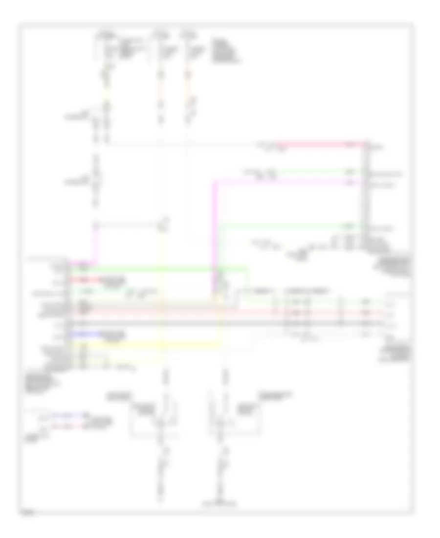
PASSIVE RESTRAINTS
Passive Restraints Wiring Diagram for Infiniti M56 2013
List of elements for Passive Restraints Wiring Diagram for Infiniti M56 2013:
- (on brake pedal bracket)
- B11
- B201
- B202 (right kick panel)
- B211
- B222
- B501
- B551
- Brake pedal stroke sensor
- Buckle sw lh no
- Buckle sw rh no
- Can hi
- Can lo
- Can-h
- Can-l
- Combination meter
- Computer data lines system
- Driver side front seat
- Driver's side pre-crash seat belt control unit (base of left "b" pillar)
- E106
- E113
- Fuse & fusible link block (right rear of engine compartment)
- Fuse 10a
- Fuse block (j/b) (behind left end of dash)
- Fusible link j 30a
- Fusible link k 30a
- Gnd
- Hot at all times
- Local comm 1
- Local comm 2
- M117
- Motor bat
- Motor gnd
- Out 1
- Out 2
- Passenger side front seat
- Passenger side pre-crash seat belt control unit (base of right "b" pillar)
- Pcb harness m23
- Pcb harness m27
- Pnk
- Red
- Seat belt buckle switch
- Sens gnd 1
- Sens power 1
- Shield
- Shield gnd
- Sig bat
- Sig gnd
- Vcc
 Čeština
 Dansk
Dansk Deutsch
 Ελληνικά
 English
 English
 Español
 Suomi
Suomi Français
 עברית
עברית Hrvatski
 Magyar
 Italiano
 日本語
日本語 한국어
한국어 Nederlands
 Polski
 Português
 Português
 Română
 Русский
 Slovenčina
 Slovenščina
 Svenska
 Türkçe
 中文 (中国)
 Français