CRUISE CONTROL
2.0L
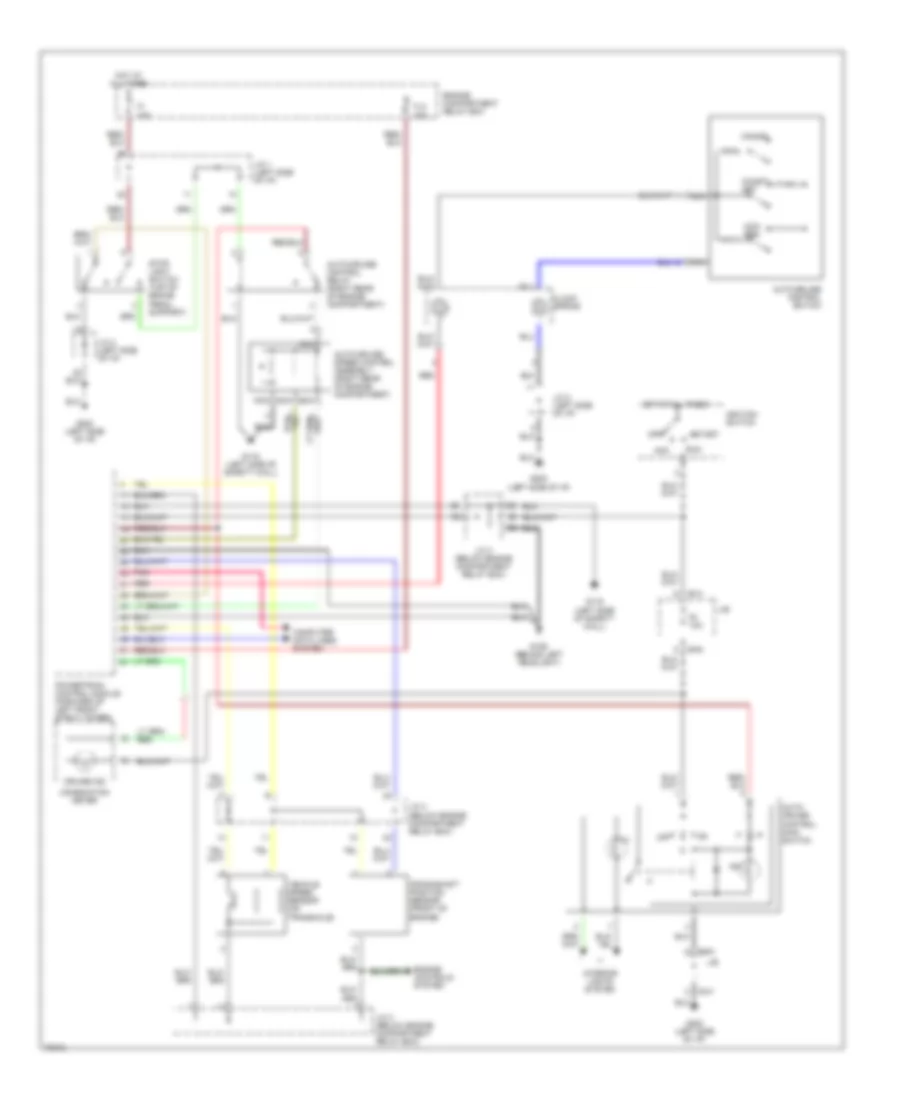
2.0L, Cruise Control Wiring Diagram, A/T for Dodge Avenger ES 1995
 https://portal-diagnostov.com/license.html
Automotive Electricians Portal FZCO
Automotive Electricians Portal FZCO
https://portal-diagnostov.com/license.html
https://portal-diagnostov.com/license.html
Automotive Electricians Portal FZCO
Automotive Electricians Portal FZCO
List of elements for 2.0L, Cruise Control Wiring Diagram, A/T for Dodge Avenger ES 1995:
- Acc
- Acc/ res
- Auto- cruise control main switch
- Auto-cruise control relay (right rear of engine compartment)
- Auto-cruise control switch
- Auto-cruise speed control assembly (right rear of engine compartment)
- B-41
- B-54
- Cancel
- Clock spring
- Coast/ set
- Combination meter
- Computer data lines system
- Cruise ind
- Eatx-ecm (left side of engine compartment)
- Engine compartment relay box
- F1 15a
- F8 10a
- Fl3 30a
- G106 (behind left headlight)
- G116 (left side of safety wall)
- G202 (left side of i/p)
- Hot at all times
- Ignition switch
- Ill
- Ind
- Input speed sensor (on transaxle)
- Interior lights system
- J/b
- J/c 1 (left side of i/p)
- J/c 2 (left side of i/p)
- J/c 3 (below engine compartment relay box)
- J/c 4 (below engine compartment relay box)
- Nca
- Off
- Output speed sensor (on transaxle)
- Park/ neutral position switch (top of trans)
- Pnk
- Powertrain control module (forward of left front strut tower)
- Red
- Run
- Start
- Starting/ charging system
- Stop light switch (top of brake pedal support)
- Transmissions system
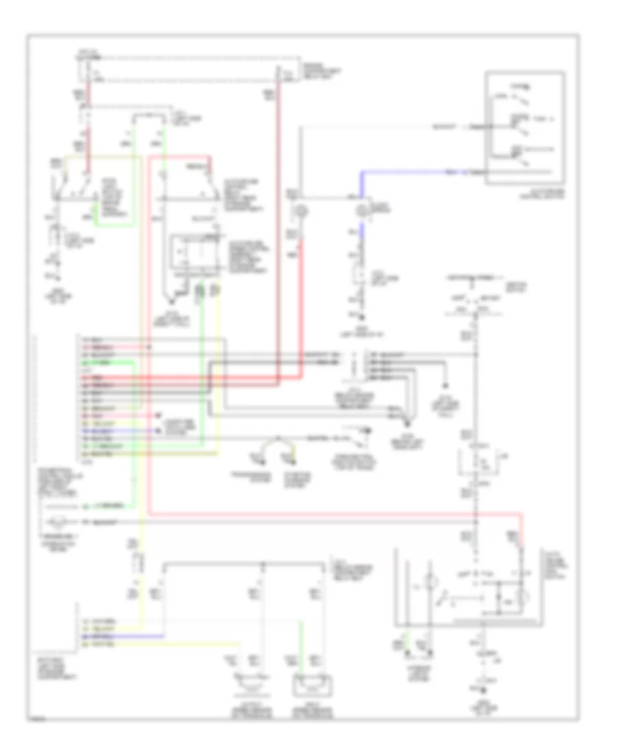
2.0L, Cruise Control Wiring Diagram, M/T for Dodge Avenger ES 1995
List of elements for 2.0L, Cruise Control Wiring Diagram, M/T for Dodge Avenger ES 1995:
- Acc
- Acc/ res
- Auto- cruise control main switch
- Auto-cruise control relay (right rear of engine compartment)
- Auto-cruise control switch
- Auto-cruise speed control assembly (right rear of engine compartment)
- B-41
- B-54
- Cancel
- Clock spring
- Coast/ set
- Combination meter
- Computer data lines system
- Crankshaft position sensor (front of engine)
- Cruise ind
- Engine compartment relay box
- Engine controls system
- F1 15a
- F8 10a
- Fl3 30a
- G106 (behind left headlight)
- G116 (left side of safety wall)
- G202 (left side of i/p)
- Hot at all times
- Ignition switch
- Ill
- Ind
- Interior lights system
- J/b
- J/c 1 (left side of i/p)
- J/c 2 (left side of i/p)
- J/c 3 (below engine compartment relay box)
- J/c 4 (below engine compartment relay box)
- Nca
- Off
- Pnk
- Powertrain control module (forward of left front strut tower)
- Red
- Run
- Start
- Stop light switch (top of brake pedal support)
- Vehicle speed sensor (on transaxle)
2.5L
2.5L, Cruise Control Wiring Diagram for Dodge Avenger ES 1995
List of elements for 2.5L, Cruise Control Wiring Diagram for Dodge Avenger ES 1995:
- A-77
- A-78
- Acc
- Acc/ res
- Auto- cruise control main switch
- Auto-cruise control relay (right rear of engine compartment)
- Auto-cruise control switch
- Auto-cruise speed control assembly (right rear of engine compartment)
- B-41
- B-54
- Cancel
- Clock spring
- Coast/ set
- Combination meter
- Computer data lines system
- Cruise ind
- Eatx-ecm (left side of engine compartment)
- Engine compartment relay box
- F1 15a
- F8 10a
- Fl3 30a
- G106 (behind left headlight)
- G116 (left side of safety wall)
- G202 (left side of i/p)
- Hot at all times
- Ignition switch
- Ill
- Ind
- Input speed sensor (on transaxle)
- Interior lights system
- J/b
- J/c 1 (left side of i/p)
- J/c 2 (left side of i/p)
- J/c 3 (below engine compartment relay box)
- J/c 4 (below engine compartment relay box)
- Nca
- Off
- Output speed sensor (on transaxle)
- Park/neutral position switch (top of trans)
- Pnk
- Powertrain control module (forward of left front strut tower)
- Red
- Run
- Start
- Starting/ charging system
- Stop light switch (top of brake pedal support)
- Transmissions system

 Čeština
 Dansk
Dansk Deutsch
 Ελληνικά
 English
 English
 Español
 Suomi
Suomi Français
 עברית
עברית Hrvatski
 Magyar
 Italiano
 日本語
日本語 한국어
한국어 Nederlands
 Polski
 Português
 Português
 Română
 Русский
 Slovenčina
 Slovenščina
 Svenska
 Türkçe
 中文 (中国)