SUPPLEMENTAL RESTRAINTS
Supplemental Restraint Wiring Diagram for Dodge Avenger ES 1995
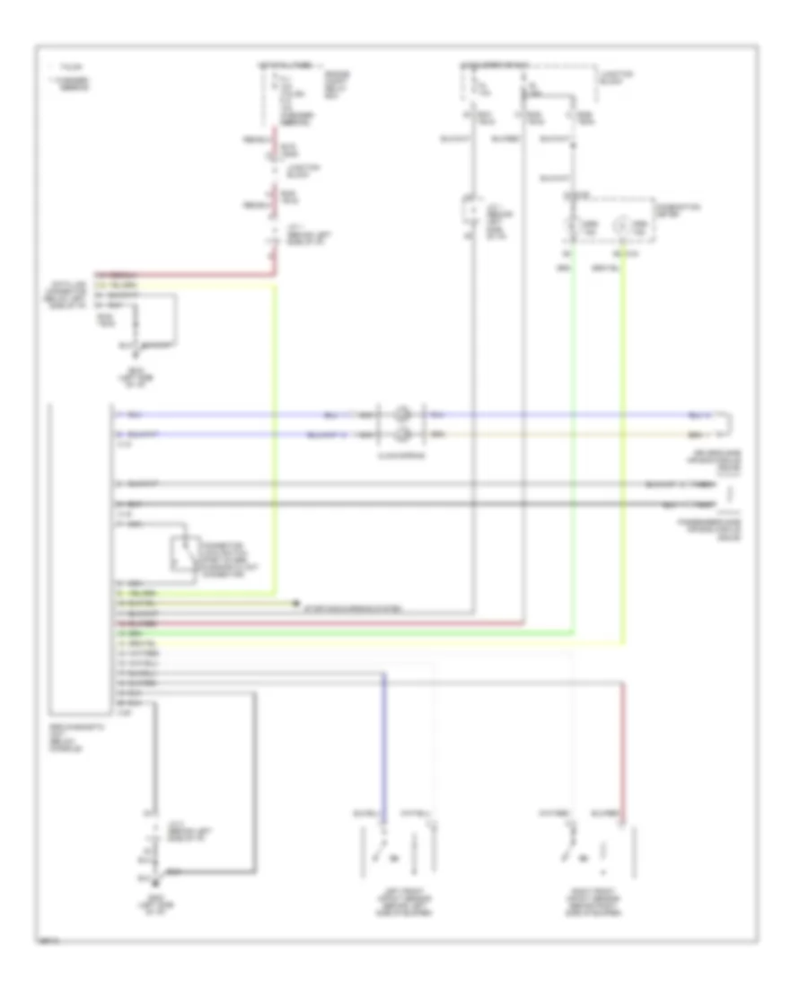
List of elements for Supplemental Restraint Wiring Diagram for Dodge Avenger ES 1995:
- ** avenger/
- **b-42
- *b-38 **b-30
- *b-50
- *b-50 **b-42
- *b-51 **b-43
- *b-66 **b-54
- *b-75 **b-63
- C-04
- C-05
- C-18
- C-19
- C-20
- Clock spring
- Combination meter
- Connector lock switch (part of srs diagnostic unit connector)
- Data link connector (below left side of i/p)
- Driver's side air bag module (squib)
- Engine compt relay box
- F11 10a (talon) f10 10a (avenger/ sebring)
- F4 10a
- F8 10a
- G202 (left side of i/p)
- Hot at all times
- Hot in start or run
- J/c 1 (behind left side of i/p)
- J/c 2 (behind left side of i/p)
- Junction block
- Left front impact sensor (behind left side of bumper)
- Nca
- Passenger's side air bag module (squib)
- Right front impact sensor (behind right side of bumper)
- Sebring
- Srs diagnostic unit (below console)
- Srs ind.
- Starting/charging system
- Talon
 Čeština
 Dansk
Dansk Deutsch
 Ελληνικά
 English
 English
 Español
 Suomi
Suomi Français
 עברית
עברית Hrvatski
 Magyar
 Italiano
 日本語
日本語 한국어
한국어 Nederlands
 Polski
 Português
 Português
 Română
 Русский
 Slovenčina
 Slovenščina
 Svenska
 Türkçe
 中文 (中国)
 Français