ELECTRONIC POWER STEERING
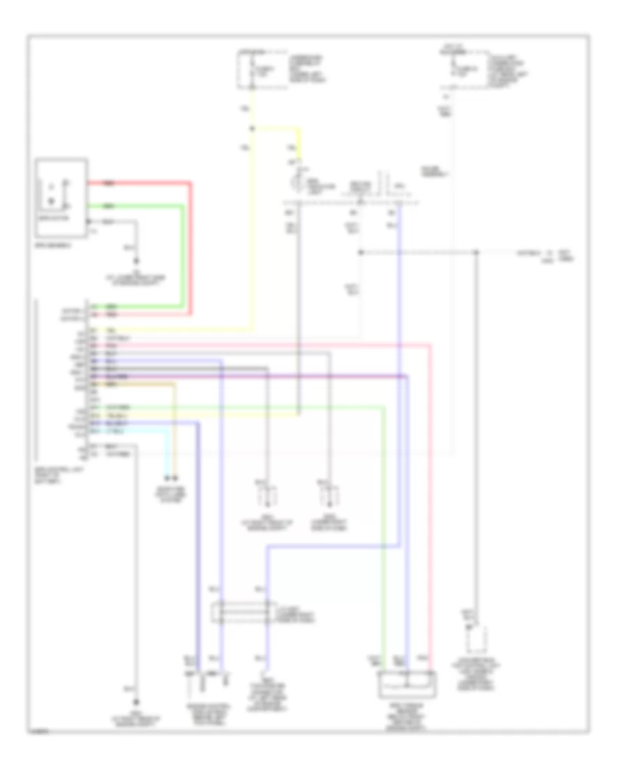
Electronic Power Steering Wiring Diagram for Honda S2000 CR 2009
List of elements for Electronic Power Steering Wiring Diagram for Honda S2000 CR 2009:
- (not used) c403
- Auxiliary under-hood fuse box (at rear left of engine compt)
- B10
- B11
- B12
- B13
- B14
- B21
- Computer data lines system
- Convertible top control unit (usa: base & canada) (under right side of dash)
- Cpu
- Dlc
- Driving circuit
- E16
- E25
- Engine control module (ecm) (behind left kick panel)
- Eps control unit (right of battery)
- Eps gearbox
- Eps indicator light
- Eps motor
- Eps torque sensor (below front center of engine compt)
- Epsld
- Fuse 33 70a
- Fuse 5 7.5a
- G201 (at right front of engine compt)
- G351 (at right rear of engine compt)
- G4 (at lower front side of engine compt)
- G402 (under right side of dash)
- Gauge assembly
- Gnd 1
- Gnd 2
- Hot at all times
- Hot in on
- Ig1
- J/c c507 (under right side of dash)
- Motor (+)
- Motor (-)
- Nep
- Pnk
- Ps-sig
- Pvf
- Red
- Scs
- Test tachometer connector (at left rear of engine compartment)
- Under-dash fuse/relay box (under left side of dash)
- Vs1
- Vs2
- Vsp
- Wlp
 Čeština
 Dansk
Dansk Deutsch
 Ελληνικά
 English
 English
 Español
 Suomi
Suomi Français
 עברית
עברית Hrvatski
 Magyar
 Italiano
 日本語
日本語 한국어
한국어 Nederlands
 Polski
 Português
 Português
 Română
 Русский
 Slovenčina
 Slovenščina
 Svenska
 Türkçe
 中文 (中国)
 Français