AUTOMOTIVE ELECTRICIANS PORTAL

TRUNK, TAILGATE, FUEL DOOR – Honda Odyssey EX-L 2014 – SYSTEM WIRING DIAGRAMS

TRUNK, TAILGATE, FUEL DOOR

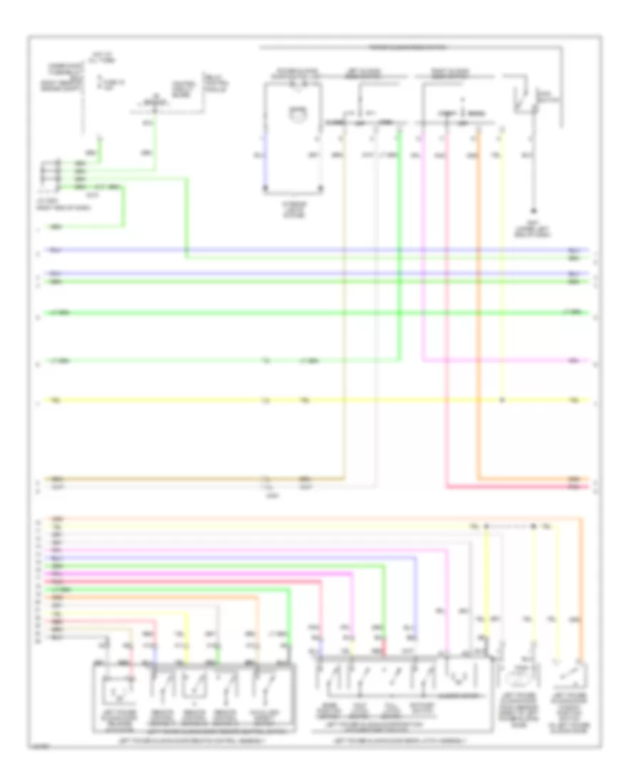
Power Sliding Door Wiring Diagram (1 of 4) for Honda Odyssey EX-L 2014

Power Sliding Door Wiring Diagram (1 of 4) for Honda Odyssey EX-L 2014 https://portal-diagnostov.com/license.html
https://portal-diagnostov.com/license.html Automotive Electricians Portal FZCO Automotive Electricians Portal FZCO
Download PDF file

List of elements for Power Sliding Door Wiring Diagram (1 of 4) for Honda Odyssey EX-L 2014:

  • (left "c" pillar)
  • (left center of dash) keyless access control unit
  • +b backup
  • A10
  • A11
  • A12
  • Atp-p
  • Atpp
  • B-can hi
  • B-can lo
  • B10
  • B11
  • B12
  • B13
  • B14
  • B15
  • B26
  • Bpcl
  • Bpop
  • C10
  • C605
  • C606
  • C681
  • C682
  • Canh
  • Canl
  • Child
  • Clm+
  • Clm-
  • Clmp
  • Close
  • Computer data lines system
  • Drcl
  • Driver's micu
  • Driver's under-dash fuse/relay box (left end of dash)
  • Drop
  • E19
  • E23
  • Ec+
  • Ec-
  • F/l
  • F24
  • Fgnd
  • Fuel fill door relay
  • Fuel lid open rly
  • Fuel lid sw
  • Fuse 13 7.5a
  • Fuse 33 40a
  • Fuse 4 10a
  • Fuse 9 20a
  • G602
  • G602 (left "c" pillar)
  • H/l
  • Hot at all times
  • Hot in on or start
  • Ig1
  • Interior lights system
  • L/p
  • Left b-pillar power sliding door switch (rear side of left "b" pillar)
  • Left cess articulated harness
  • Left power side motor
  • Left power side motor electromagnetic clutch
  • Left power sliding door control unit (behind left rear side trim panel)
  • Main
  • Open
  • Pgd1
  • Pgd2
  • Pnk
  • Q18
  • R/c1
  • R/c2
  • R/c3
  • Rear fuse box (behind left rear side trim panel)
  • Rear micu
  • Red
  • Rem+
  • Scom
  • Sdw
  • Sgd
  • Slmcl
  • Slmop
  • Tse
  • Vbu
  • Vmp1
  • Vmp2

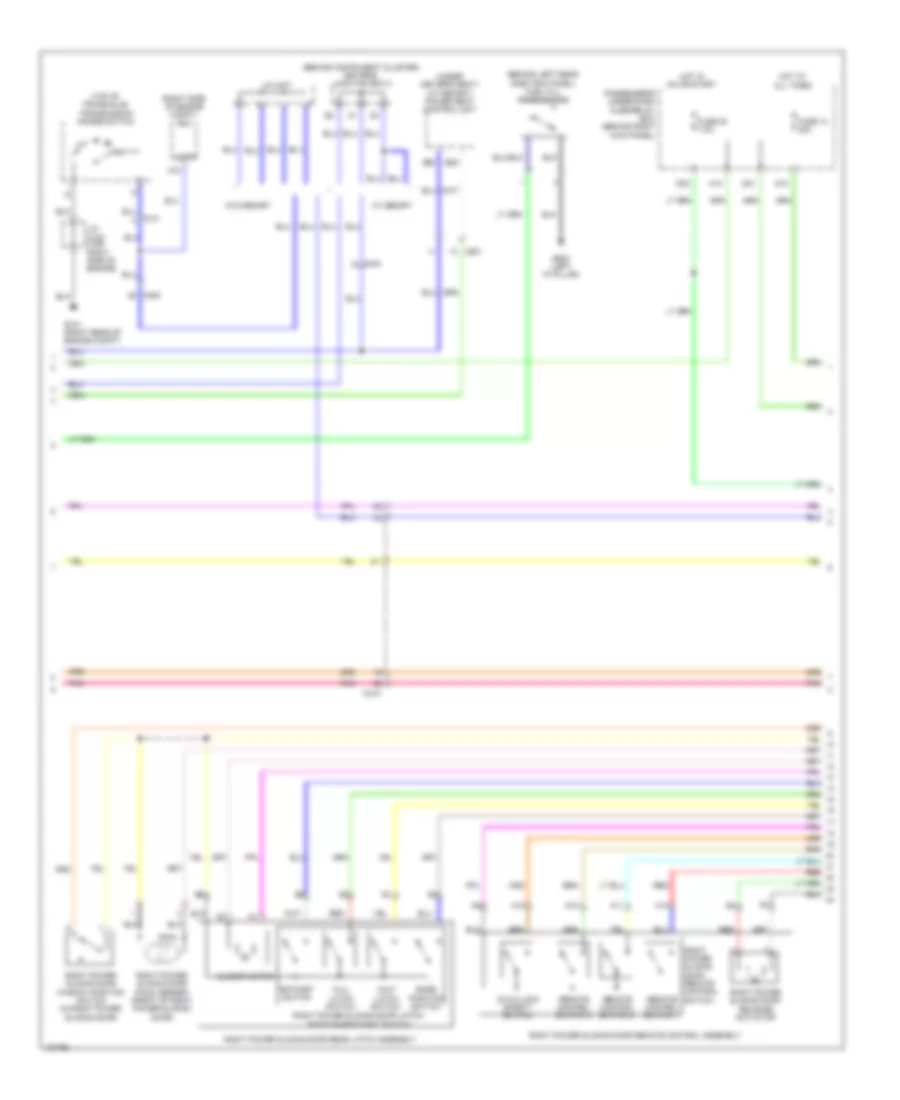
Power Sliding Door Wiring Diagram (2 of 4) for Honda Odyssey EX-L 2014

Power Sliding Door Wiring Diagram (2 of 4) for Honda Odyssey EX-L 2014 https://portal-diagnostov.com/license.html
https://portal-diagnostov.com/license.html Automotive Electricians Portal FZCO Automotive Electricians Portal FZCO
Obtenez l'accès à tous les schémas de câblage de la voitureDownload PDF file

List of elements for Power Sliding Door Wiring Diagram (2 of 4) for Honda Odyssey EX-L 2014:

  • (right end of dash)
  • +b backup
  • A10
  • A11
  • A12
  • A13
  • B10
  • Base position switch
  • C210
  • C404
  • Child lock safety switch
  • Close
  • Closer motor
  • Control circuit board
  • Full latch switch
  • Fuse 16 10a
  • G401 (upper left end of dash)
  • Half latch switch
  • Hot at all times
  • Interior lights system
  • J/c c203
  • Left power sliding door pinch sensor (front of left power sliding door)
  • Left power sliding door rear latch assembly
  • Left power sliding door release actuator
  • Left power sliding door remote control assembly
  • Left power sliding door remote control switch
  • Left power sliding door window position switch (in left power sliding door)
  • Left power sliding door/position/ latch/ratchet switch
  • Left sliding door switch
  • Main switch
  • Off
  • On ind
  • Open
  • Pnk
  • Power sliding door switch
  • Power sliding door switch light
  • Ratchet switch
  • Red
  • Relay control module
  • Remote control switch 1
  • Remote control switch 2
  • Remote control switch 3
  • Right sliding door switch
  • Under-hood fuse/relay box (right rear of engine compt)

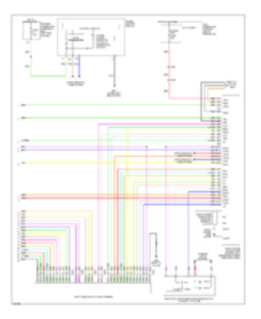
Power Sliding Door Wiring Diagram (3 of 4) for Honda Odyssey EX-L 2014

Power Sliding Door Wiring Diagram (3 of 4) for Honda Odyssey EX-L 2014 https://portal-diagnostov.com/license.html
https://portal-diagnostov.com/license.html Automotive Electricians Portal FZCO Automotive Electricians Portal FZCO
Obtenez l'accès à tous les schémas de câblage de la voitureDownload PDF file

List of elements for Power Sliding Door Wiring Diagram (3 of 4) for Honda Odyssey EX-L 2014:

  • (behind instrument cluster) driver's junction box 2
  • (behind left rear side trim panel) fuel fill door switch
  • (right rear of engine compt)
  • (right side of engine compt) pcm
  • (top of transaxle)
  • (under driver's seat) (w/ memory) power seat control unit
  • A10
  • A11
  • A12
  • A13
  • A16
  • Atpp
  • B25
  • B35
  • Base position switch
  • C101
  • C205
  • C404
  • C415
  • C601
  • Child lock safety switch
  • Closer motor
  • D12
  • D21
  • D32
  • Full latch switch
  • Fuse 13 20a
  • Fuse 20 7.5a
  • G101
  • G602 (left "c" pillar)
  • Half latch switch
  • Hot at all times
  • Hot in on or start
  • J/c c102 (top right side of engine)
  • J/c c407
  • Passenger's under-dash fuse/relay box (behind right kick panel)
  • Pnk
  • Ratchet switch
  • Red
  • Remote control switch 1
  • Remote control switch 2
  • Remote control switch 3
  • Right power sliding door latch/ position/ratchet switch
  • Right power sliding door pinch sensor (front of right power sliding door)
  • Right power sliding door rear latch assembly
  • Right power sliding door release actuator
  • Right power sliding door remote control assembly
  • Right power sliding door remote control switch
  • Right power sliding door window position switch (in right power sliding door)
  • Transmission range switch
  • W/ memory
  • W/o memory

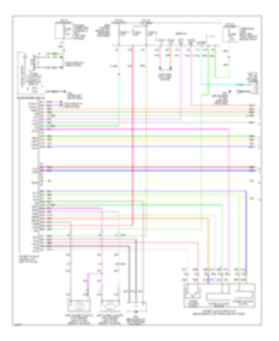
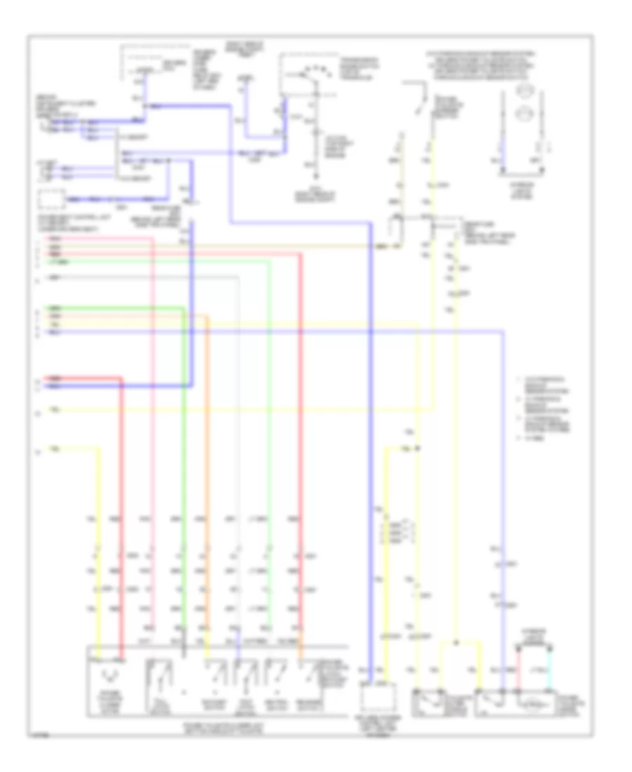
Power Sliding Door Wiring Diagram (4 of 4) for Honda Odyssey EX-L 2014

Power Sliding Door Wiring Diagram (4 of 4) for Honda Odyssey EX-L 2014 https://portal-diagnostov.com/license.html
https://portal-diagnostov.com/license.html Automotive Electricians Portal FZCO Automotive Electricians Portal FZCO
Obtenez l'accès à tous les schémas de câblage de la voitureDownload PDF file

List of elements for Power Sliding Door Wiring Diagram (4 of 4) for Honda Odyssey EX-L 2014:

  • (right "c" pillar)
  • (upper left end of dash)
  • A10
  • A11
  • A12
  • As psd mtr fuse 40a
  • Atpp
  • B-can transceiver
  • B10
  • B11
  • B12
  • B13
  • B14
  • B15
  • Bpcl
  • Bpop
  • C206
  • C208
  • C652
  • C653
  • C691
  • C692
  • Canh
  • Canl
  • Child
  • Clm+
  • Clm-
  • Clmp
  • Close
  • Computer data lines system
  • Control circuits
  • Drcl
  • Driver's under-dash fuse/relay box (left end of dash)
  • Drop
  • Ec+
  • Ec-
  • F/l
  • Fgnd
  • Fuse 7.5a
  • G401
  • G652
  • G652 (right "c" pillar)
  • Gauge control module
  • H/l
  • Hot at all times
  • Hot in on or start
  • Ig1
  • Interior lights system
  • L/p
  • Main
  • Main under-hood fuse box (above transaxle)
  • Multi-fuse 3
  • Open
  • Pgd1
  • Pgd2
  • Pnk
  • Power sliding doors ind (w/o multi- information switch)
  • R/c1
  • R/c2
  • R/c3
  • Red
  • Rem+
  • Right b-pillar power sliding door switch (on right "c" pillar)
  • Right cess articulated harness
  • Right power side motor
  • Right power side motor electro- magnetic clutch
  • Right power sliding door control unit (behind right rear side trim panel)
  • Scom
  • Sdw
  • Sgd
  • Slmcl
  • Slmop
  • Tse
  • Vbu
  • Vmp1
  • Vmp2

Power Tailgate Wiring Diagram (1 of 2) for Honda Odyssey EX-L 2014

Power Tailgate Wiring Diagram (1 of 2) for Honda Odyssey EX-L 2014 https://portal-diagnostov.com/license.html
https://portal-diagnostov.com/license.html Automotive Electricians Portal FZCO Automotive Electricians Portal FZCO
Obtenez l'accès à tous les schémas de câblage de la voitureDownload PDF file

List of elements for Power Tailgate Wiring Diagram (1 of 2) for Honda Odyssey EX-L 2014:

  • (left "d" pillar) keyless buzzer
  • A13
  • A14
  • A23
  • A24
  • A33
  • A40
  • A47
  • Atpp
  • B can hi
  • B can low
  • B-can h
  • B-can l
  • B10
  • B11
  • B12
  • B13
  • B14
  • B15
  • B16
  • B17
  • B18
  • B19
  • B20
  • Buzzer
  • C10
  • C11
  • C12
  • C13
  • C14
  • C801
  • C851
  • Clm+
  • Clm-
  • Clu+
  • Clu-
  • Computer data lines system
  • Control circuits
  • Driver's under-dash fuse/relay box (left end of dash)
  • Drsw
  • F-can transceiver
  • Full
  • Fuse 1 20a
  • Fuse 10a
  • Fuse 13 7.5a
  • Fuse 14 40a
  • Fuse 7.5a
  • G401 (upper left end of dash)
  • G801 (behind rear of left rear side trim panel)
  • Gauge control module
  • Gtcl
  • Half
  • Hot at all times
  • Hot in on or start
  • Ig1
  • Left power tailgate pinch sensor (left outer edge of tailgate)
  • Ntl
  • Ohsw
  • Pg1
  • Pg2
  • Pnk
  • Power tailgate clutch
  • Power tailgate control unit (left "d" pillar)
  • Power tailgate drive unit (behind rear of left rear side trim panel)
  • Power tailgate ind (w/o multi- information display)
  • Power tailgate motor
  • Power tailgate sensor
  • Ptg full
  • Ptm+
  • Ptm-
  • Ract
  • Rear fuse box (behind left rear side trim panel)
  • Rear mcu
  • Red
  • Right power tailgate pinch sensor (right outer edge of tailgate)
  • Scom
  • Seg1
  • Seg2
  • Seg3
  • Sena
  • Senb
  • Svcc
  • T gate sw+
  • Tsel
  • Tser
  • Under-hood fuse/ relay box (right rear of engine compt)
  • Vbu
  • Vmp1
  • Vmp2

Power Tailgate Wiring Diagram (2 of 2) for Honda Odyssey EX-L 2014

Power Tailgate Wiring Diagram (2 of 2) for Honda Odyssey EX-L 2014 https://portal-diagnostov.com/license.html
https://portal-diagnostov.com/license.html Automotive Electricians Portal FZCO Automotive Electricians Portal FZCO
Obtenez l'accès à tous les schémas de câblage de la voitureDownload PDF file

List of elements for Power Tailgate Wiring Diagram (2 of 2) for Honda Odyssey EX-L 2014:

  • (behind instrument cluster) driver's junction box 2
  • (right side of engine compt) pcm
  • (w/o parking & backup sensor system) driver's power tailgate switch (w/ parking & backup sensor system) driver's power tailgate switch/ parking & backup sensor switch
  • A15
  • A27
  • Atp-p
  • Atpp
  • B18
  • B35
  • C10
  • C101
  • C16
  • C205
  • C403
  • C404
  • C601
  • C609
  • C801
  • C802
  • C851
  • C852
  • Closer motor
  • Driver's micu
  • Driver's under- dash fuse/ relay box (left end of dash)
  • Full latch switch
  • G101 (right rear of engine compt)
  • Half latch switch
  • Interior lights system
  • J/c c102 (top right side of engine)
  • J/c c407
  • Keyless access control unit (left center of dash)
  • N d
  • Neutral switch
  • Pnk
  • Power seat control unit (w/ memory) (under driver's seat)
  • Power tailgate
  • Power tailgate closer unit (bottom middle of tailgate)
  • Power tailgate inside switch
  • Power tailgate latch/ ratchet switch
  • Power tailgate opener switch
  • Q18
  • Ratchet switch
  • Rear fuse box (behind left rear side trim panel)
  • Red
  • Release switch
  • Tailgate outer handle switch
  • Transmission range switch (top of transaxle)
  • W/ memory
  • W/ parking & backup sensor system
  • W/ parking & backup sensor system w/o res
  • W/ res
  • W/o memory
  • W/o parking & backup sensor system

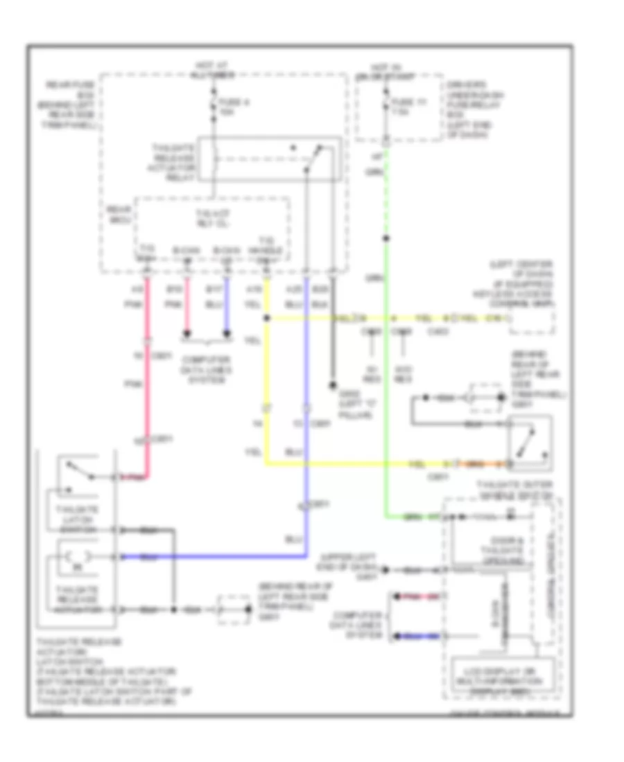
Tailgate Release Wiring Diagram for Honda Odyssey EX-L 2014

Tailgate Release Wiring Diagram for Honda Odyssey EX-L 2014 https://portal-diagnostov.com/license.html
https://portal-diagnostov.com/license.html Automotive Electricians Portal FZCO Automotive Electricians Portal FZCO
Obtenez l'accès à tous les schémas de câblage de la voitureDownload PDF file

List of elements for Tailgate Release Wiring Diagram for Honda Odyssey EX-L 2014:

  • (behind rear of left rear side trim panel) g801
  • (left center of dash) (if equipped) keyless access control unit
  • (upper left end of dash) g401
  • A16
  • A25
  • B-can hi
  • B-can lo
  • B10
  • B17
  • B26
  • C16
  • C403
  • C609
  • C801
  • C851
  • Computer data lines system
  • Control circuits
  • Door & tailgate open ind
  • Driver's under-dash fuse/relay box (left end of dash)
  • Fuse 11 7.5a
  • Fuse 4 10a
  • G602 (left "c"
  • Gauge control module
  • Hot at all times
  • Hot in on or start
  • Lcd display or multi-information display (mid)
  • Pillar)
  • Pnk
  • Rear fuse box (behind left rear side trim panel)
  • Rear micu
  • T/g act rly cl-
  • T/g handle sw+
  • T/g sw+
  • Tailgate latch switch
  • Tailgate outer handle switch
  • Tailgate release actuator
  • Tailgate release actuator relay
  • Tailgate release actuator/ latch switch (tailgate release actuator: bottom middle of tailgate) (tailgate latch switch: part of tailgate release actuator)
  • Transceiver b-can
  • W/ res
  • W/o res