ANTI-LOCK BRAKES
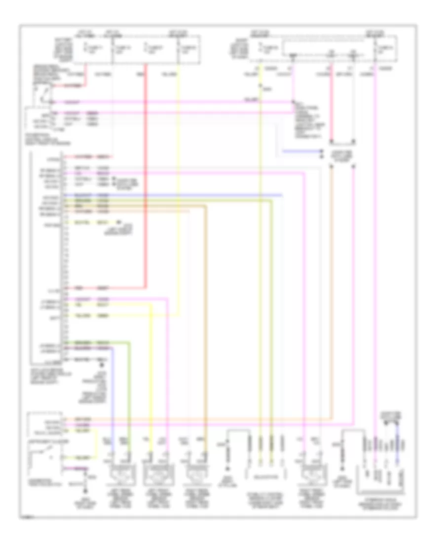
Anti-lock Brakes Wiring Diagram for Lincoln MKX 2010
List of elements for Anti-lock Brakes Wiring Diagram for Lincoln MKX 2010:
- (brake pedal support bracket) brake pedal position (bpp) switch
- Anti-lock brake system (abs) module (left rear of engine compt)
- Batt
- Battery junction box (bjb) (left side of engine compt)
- Bpp
- C175b
- C2280b
- C2280d
- Cbb50
- Cbp34
- Ces09
- Computer data lines system
- Fuse 15 40a
- Fuse 34 5a
- Fuse 35 10a
- Fuse 50 10a
- Fuse 57 40a
- Fuse 71 10a
- G102 (early production) g103 (late production) (left side of engine compt)
- G103 (left side of engine compt)
- G203 (right side of dash)
- G205 (left side of dash)
- G404 (right "d" pillar)
- Gd115
- Gd121
- Gnd
- Hazard/pad/ traction switch
- Hot at all times
- Hot in on or start
- Hs can +
- Hs can -
- Hs can2 +
- Hs can2 -
- Instrument cluster
- Left front wheel speed sensor (left front wheel hub)
- Left rear wheel speed sensor (left rear wheel hub)
- Lf sens hi
- Lf sens lo
- Lr sens hi
- Lr sens lo
- Ms can +
- Ms can -
- Ms can+
- Ms can-
- Mtr b+
- Nca
- Pmp gnd
- Powertrain control module (right front of engine)
- Rca17
- Rca18
- Rca19
- Rca20
- Red
- Rf sens hi
- Rf sens lo
- Right front wheel speed sensor (right front wheel hub)
- Right rear wheel speed sensor (right rear wheel hub)
- Rr sens hi
- Rr sens lo
- S208
- S211 (dash panel wiring harness, to headlight junction, near breakout to joint connector 7)
- S232
- S308
- S408
- Sbb15
- Sbb57
- Smart junction box (sjb) (left side of dash)
- Solid state
- Stability control sensor cluster (under right side of rear seat)
- Steering angle sensor module (sasm) (steering column)
- Tr ctl on/off
- Vca03
- Vca04
- Vca05
- Vca06
- Vca23
- Vca24
- Vdb04
- Vdb05
- Vlv b+
- Vlv gnd
 Čeština
 Dansk
Dansk Deutsch
 Ελληνικά
 English
 English
 Español
 Suomi
Suomi Français
 עברית
עברית Hrvatski
 Magyar
 Italiano
 日本語
日本語 한국어
한국어 Nederlands
 Polski
 Português
 Português
 Română
 Русский
 Slovenčina
 Slovenščina
 Svenska
 Türkçe
 中文 (中国)
 Français