AIR CONDITIONING
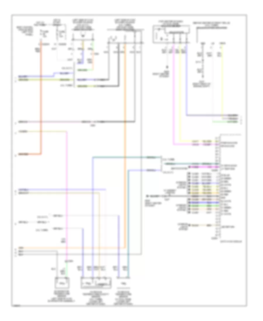
Automatic A/C Wiring Diagram (1 of 3) for Ford Edge SE 2014
 https://portal-diagnostov.com/license.html
Automotive Electricians Portal FZCO
Automotive Electricians Portal FZCO
https://portal-diagnostov.com/license.html
https://portal-diagnostov.com/license.html
Automotive Electricians Portal FZCO
Automotive Electricians Portal FZCO
List of elements for Automatic A/C Wiring Diagram (1 of 3) for Ford Edge SE 2014:
- (a/c wiring harness, near breakout to air inlet mode door actuator)
- (main wiring harness, near breakout to accessory protocol interface module)
- (near blower motor) blower motor speed control
- (right side of dash) blower motor
- Battery junction box (bjb) (left side of engine compt)
- Blower motor relay
- Blwr rly
- C215
- C228a
- C228b
- C260
- C264
- Ch102
- Ch122
- Ch123
- Ch207
- Ch208
- Ch212
- Ch213
- Ch228
- Ch229
- Ch238
- Ch239
- Chs02
- Chs07
- Computer data lines system
- Datc hvac module
- Defogger system
- Defrost/panel/ floor mode door actuator (upper left side of hvac unit)
- Defrst req
- Edge w/ heated seats
- Evap
- Feedback
- Fuse 30a
- Fuse 40a
- Fuse 5a
- G205 (right center of dash)
- Gd115
- Gnd
- Hot at all times
- Hot in start or run
- Humidity signal
- Left temperature blend door actuator (left side of hvac unit)
- Lf heater
- Lh111
- Module) s219
- Ms can +
- Ms can -
- Mtr +
- Mtr -
- Power distribution system
- Red
- Rf heater
- Rf temp sns
- Rh111
- Right temperature blend door actuator (lower right side of hvac unit)
- S207
- S216
- S217 (a/c wiring harness, near breakout to air inlet mode door actuator)
- S218
- S245 (main wiring harness, near breakout to g205)
- Sbb28
- Sbp46
- Seats system
- Sig return
- Var blw feed
- Var blwr ctrl
- Vbatt
- Vdb06
- Vdb07
- Vh101
- Vh406
- Vh413
- Vh436
- Vh438
- Vh440
- Vh441
- Vhs27
- Vref
Automatic A/C Wiring Diagram (2 of 3) for Ford Edge SE 2014
List of elements for Automatic A/C Wiring Diagram (2 of 3) for Ford Edge SE 2014:
- (behind center of front grille) (2.0l turbo) grille shutter actuator
- (left side of hvac blower housing) (2.0l turbo) air inlet mode door actuator
- (left side of hvac blower housing) (3.5l & 3.7l) air inlet mode door actuator
- (top center of dash) (w/ dual zone) sunload sensor
- 2.0l turbo
- 3.5l & 3.7l
- Body control module (bcm) (left kick panel)
- C2280a
- C2280b
- C228b
- C228c
- C237
- C264
- Cln44
- Cln45
- Cln46
- Cln48
- Cln49
- Cln50
- Cln51
- Cln52
- Cln53
- Cln57
- Cln58
- Cln59
- Datc hvac module
- Dr sunload
- Evaporator temperature sensor (left side of hvac evaporator assembly)
- Fuse 10a
- G107 (right front of engine compt)
- G205 (right center of dash)
- Gd908
- Gnd
- Hot at all times
- Hot in start or run
- Humidity
- In vehicle sig
- In-vehicle temperature sensor (w/ dual zone) (lower left center of dash)
- In-vehicle temperature/humidity sensor (2.0l turbo) (lower left center of dash)
- Interior lights system
- Led return
- Lf temp sns
- Lin
- Nca
- Pass sunload
- Rln44
- S114
- Seats system
- Solid state
- Vh414
- Vh416
- Vh417
- Vhs26
- Vpwr
- W/ ambient lighting
- Z1 green
- Z1 red
- Z1 white
- Z2 green
- Z2 red
- Z2 white
- Z3 green
- Z3 red
- Z3 white
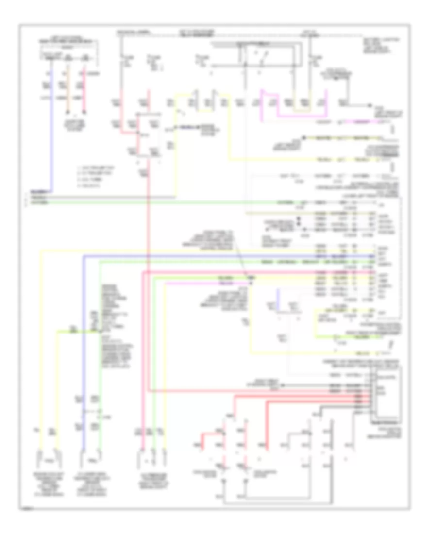
Automatic A/C Wiring Diagram (3 of 3) for Ford Edge SE 2014
List of elements for Automatic A/C Wiring Diagram (3 of 3) for Ford Edge SE 2014:
- (3.5l & 3.7l) a/c compressor clutch diode
- (dash panel to headlight junction wiring harness, near breakout to powertrain control module)
- (engine control sensor & fuel charge wiring harness, near breakout to coil on plug 1) (2.0l turbo) s176
- (engine control sensor & fuel charge wiring harness, near breakout to coil on plug 3)
- (left kick panel) body control module (bcm)
- (or re454)
- (right front of engine compt) g107
- 2.0l turbo
- 3.5l & 3.7l
- A/c clutch relay
- A/c compressor clutch field coil (a/c compressor)
- A/c pressure transducer (right front of engine compt)
- Aat
- Accr
- Acpt
- Ambient air temperature (aat) sensor (behind right side of front grille)
- Auto lamp sens in
- Battery junction box (bjb) (left side of engine compt)
- C110
- C1381b
- C1381e
- C140
- C175b
- C175e
- C192
- C2280b
- Ch302
- Cht
- Computer data lines system
- Cooling fan module (behind radiator)
- Cooling fan motor
- Cylinder head temperature (cht) sensor (3.5l & 3.7l) (front of right cylinder bank)
- Ect
- Electronics
- Engine controls system
- Engine coolant temperature sensor (2.0l turbo) (rear of cylinder bank)
- Evdc
- Externally controlled variable displacement compressor (evdc) (2.0l turbo) (lower left front of engine)
- Fan cntrl
- Fcv
- Fuse 10a
- Fuse 40a
- Fuse 60a 40a
- G103 (left rear of engine compt)
- G105 (left front of engine compt)
- G109 (on right front shock tower)
- Gd123
- Gd124
- Gnd
- Hot at all times
- Hot w/ pcm power relay energized
- Hs can +
- Hs can -
- Le424
- Lin
- Micro
- Ms can+
- Ms can-
- Powertrain control module (pcm) (right rear of engine compt)
- Pwr
- Pwr gnd
- Re405
- Re407
- Red
- S112
- S118
- S119 (dash panel to headlight junction wiring harness, near breakout to anti-theft hood switch)
- S120
- S122
- S127 (3.5l & 3.7l)
- Sbb39
- Sigrtn
- Vdb04
- Vdb05
- Vdb06
- Vdb07
- Vdb10
- Ve462
- Ve712
- Ve716
- Vec03
- Vh407 (or ve740)
- Vh433
- Vlf14
- Vref
- W/ trailer tow
- W/o trailer tow
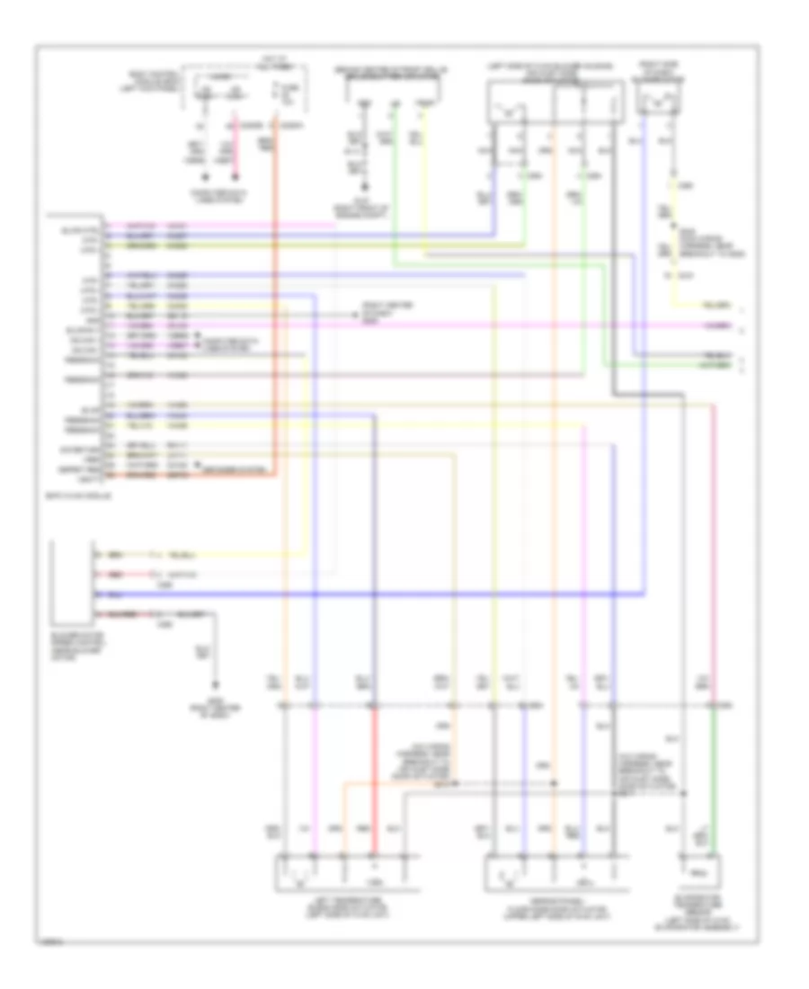
Manual A/C Wiring Diagram (1 of 2) for Ford Edge SE 2014
List of elements for Manual A/C Wiring Diagram (1 of 2) for Ford Edge SE 2014:
- (a/c wiring harness, near breakout to air inlet mode door actuator) s217
- (a/c wiring harness, near breakout to air inlet mode door actuator) s218
- (behind center of front grille) grille shutter actuator
- (left side of hvac blower housing) air inlet mode door actuator
- (right center of dash) g205
- (right side of dash) blower motor
- Blower motor speed control (near blower motor)
- Blwr ctrl
- Blwr rly
- Body control module (bcm) (left kick panel)
- C215
- C2280a
- C2280b
- C260
- C264
- Ch102
- Ch122
- Ch123
- Ch207
- Ch208
- Ch228
- Ch229
- Ch238
- Ch239
- Computer data lines system
- Defogger system
- Defrost/panel/ floor mode door actuator (upper left side of hvac unit)
- Defrst req
- Emtc hvac module
- Evap
- Evaporator temperature sensor (left side of hvac evaporator assembly)
- Feedback
- Fuse 10a
- G107 (right front of engine compt)
- G205 (right center of dash)
- Gd115
- Gnd
- Hot at all times
- Left temperature blend door actuator (left side of hvac unit)
- Lh111
- Lin
- Micro
- Ms can +
- Ms can -
- Ms can+
- Ms can-
- Mtr +
- Mtr -
- Nca
- Red
- Rh111
- S114
- S245 (main wiring harness, near breakout to g205)
- Sbp46
- Sig return
- Vbatt
- Vdb06
- Vdb07
- Vh101
- Vh406
- Vh436
- Vh438
- Vh440
- Vpwr
- Vref
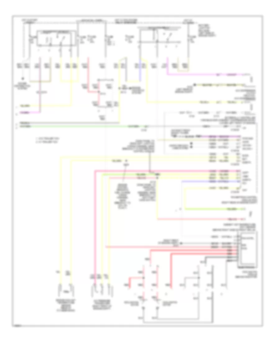
Manual A/C Wiring Diagram (2 of 2) for Ford Edge SE 2014
List of elements for Manual A/C Wiring Diagram (2 of 2) for Ford Edge SE 2014:
- (dash panel to headlight junction wiring harness, near breakout to powertrain control module)
- (engine control sensor & fuel charge wiring harness, near breakout to coil on plug 1)
- (on right front shock tower) g109
- (right front of engine compt) g107
- A/c clutch relay
- A/c compressor clutch field coil (a/c compressor)
- A/c pressure transducer (right front of engine compt)
- Aat
- Accr
- Acpt
- Ambient air temperature (aat) sensor (behind right side of front grille)
- Battery junction box (bjb) (left side of engine compt)
- Blower motor relay
- C110
- C1381b
- C1381e
- C140
- C215
- Ch302
- Computer data lines system
- Cooling fan module (behind radiator)
- Cooling fan motor
- Ect
- Electronics
- Engine controls system
- Engine coolant temperature sensor (rear of cylinder bank)
- Evdc
- Externally controlled variable displacement compressosr (evdc) (lower left front of engine)
- Fan cntrl
- Fcv
- Fuse 10a
- Fuse 40a
- Fuse 5a
- Fuse 60a 40a
- G103 (left rear of engine compt)
- Gd123
- Gd124
- Gnd
- Hot at all times
- Hot in start or run
- Hot w/ pcm power relay energized
- Hs can +
- Hs can -
- Le424
- Lin
- Power distribution system
- Powertrain control module (pcm) (right rear of engine compt)
- Pwr
- Pwr gnd
- Re407
- Re454
- Red
- S112
- S118
- S119 (dash panel to headlight junction harness, near breakout to anti-theft hood switch)
- S120
- S122
- S176
- Sbb39
- Sigrtn
- Vdb04
- Vdb05
- Vdb10
- Ve462
- Ve716
- Vec03
- Vh407
- Vh433
- Vref
- W/ trailer tow
- W/o trailer tow

 Čeština
 Dansk
Dansk Deutsch
 Ελληνικά
 English
 English
 Español
 Suomi
Suomi Français
 עברית
עברית Hrvatski
 Magyar
 Italiano
 日本語
日本語 한국어
한국어 Nederlands
 Polski
 Português
 Português
 Română
 Русский
 Slovenčina
 Slovenščina
 Svenska
 Türkçe
 中文 (中国)