POWER DISTRIBUTION
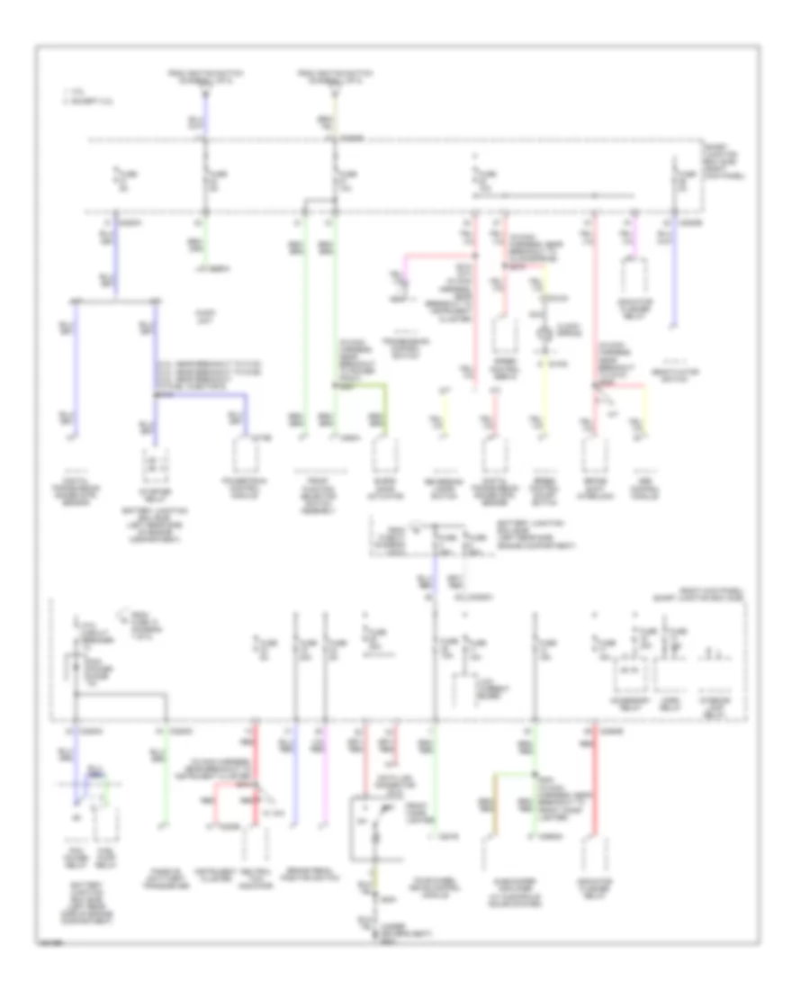
Power Distribution Wiring Diagram (1 of 2) for Ford Ranger 2007
 https://portal-diagnostov.com/license.html
Automotive Electricians Portal FZCO
Automotive Electricians Portal FZCO
https://portal-diagnostov.com/license.html
https://portal-diagnostov.com/license.html
Automotive Electricians Portal FZCO
Automotive Electricians Portal FZCO
List of elements for Power Distribution Wiring Diagram (1 of 2) for Ford Ranger 2007:
- (2.3l: near breakout to fuel injector 4) (3.0l: at breakout to c110) (4.0l: near breakout to c110)
- (in battery cable assembly, near breakout to battery)
- (in dash panel to headlight junction harness, near breakout to battery junction box) s124
- (in radio speaker jumper harness, near breakout to radio amplifier) s300
- (left rear side of engine compartment) battery junction box (bjb)
- (not used)
- (right kick panel) smart junction box (sjb)
- 2.3l
- A/c clutch relay
- Abs control module
- Acc
- Audio unit
- Battery
- Battery junction box (bjb) (left rear side of engine compartment)
- Blower motor relay
- C102a
- C102b
- C102c
- C175b
- C2041b
- C220b
- C2280a
- C2280b
- C2280c
- C281a
- C281b
- C290a
- C3154a
- Door lock/ unlock relay
- Driver door unlock relay
- Drl driver
- Engine cooling fan relay
- Evaporative emission (evap) canister vent valve
- Except 2.3l
- Exterior rear view mirror switch
- Fog lamp relay
- Four- wheel drive control module
- Four-wheel drive control module
- Fuel pump relay
- Fuse 10a
- Fuse 15a
- Fuse 20a
- Fuse 20a (2.3l)
- Fuse 30a
- Fuse 40a
- Fuse 5a
- G301 (under driver's seat)
- Generator
- Ignition switch
- Instrument cluster
- Lock
- Low current board
- Main light switch
- Multi- function switch
- Occupant classification sensor (ocs) module
- Off
- Park lamp relay
- Passenger air bag deactivation (pad) indicator
- Pcm power relay
- Power point
- Powertrain control module (pcm)
- Radio amplifier (tremor)
- Red
- Restraints control module
- Run
- S105
- S113 (in battery cable assembly, near breakout red to battery)
- S114
- S115 (in battery cable assembly, near breakout to battery)
- S200 (in main harness, near breakout to main light switch)
- S203
- S209 (in main harness, near breakout to ignition switch)
- S219 (in main harness, near breakout to g204)
- Smart junction box (sjb) (right kick panel)
- Start
- Starter motor
- Starter relay
- To fuse 22 (diagram 2 of 2)
- To fuse 27 (diagram 2 of 2)
- To fuse 3 (diagram 2 of 2)
- To ptc circuit breaker (diagram 2 of 2)
- W/ 4x4
- Windshield washer relay
- Windshield wiper motor
- Wiper high/low relay
- Wiper run/park relay
Power Distribution Wiring Diagram (2 of 2) for Ford Ranger 2007
List of elements for Power Distribution Wiring Diagram (2 of 2) for Ford Ranger 2007:
- (2.3l: near breakout to c133) (3.0l: near breakout to g106) (4.0l: near breakout to fuel injector 6) s110
- (in main harness, near breakout to c210) s208
- (in main harness, near breakout to instrument cluster) s212
- (in main harness, near breakout to power point) s227
- (right kick panel) smart junction box (sjb)
- 2.3l
- A/t
- Abs control module
- Accessory relay
- Audio unit
- Battery junction box (bjb) (left rear side engine compartment)
- Battery junction box (bjb) (left rear side of engine compartment)
- Blend door actuator
- Brake pedal position switch
- Brake shift interlock
- C175b
- C218a
- C218c
- C220b
- C2280a
- C2280b
- C2280c
- C281b
- C290a
- C294a
- C2982a
- Clock- spring
- Data link connector (dlc)
- Deactivator switch
- Digital transmission range (dtr) sensor
- Except 2.3l
- Four-wheel drive control module
- From fuse 10 (diagram 1 of 2)
- From fuse 21 (diagram 1 of 2)
- From ignition switch (diagram 1 of 2)
- Front cigar lighter
- Front function selector switch assembly
- Fuel pump relay
- Fuse 10a
- Fuse 15a
- Fuse 20a
- Fuse 2a
- Fuse 30a
- Fuse 40a
- Fuse 50a
- Fuse 5a
- Horn relay
- Indicator flasher relay
- Instrument cluster
- Interior lamp relay
- Low current board
- M/t
- Nca
- Neutral tow indicator
- Off
- Passive anti-theft transceiver
- Pcm power diode 3a
- Pcm power relay
- Powertrain control module
- Ptc circuit breaker 1a
- Red
- Reversing lamps switch
- S203
- S210 (a/t) (in main harness, near breakout to instrument cluster)
- S224 (in main harness, near breakout to red front cigar lighter)
- Smart junction box (sjb) (right kick panel)
- Speed control on/off switch
- Speed control servo
- Starter relay
- Subwoofer amplifier (w/ audiophile sound system)
- Transmission control switch
- W/ 4x4

 Čeština
 Dansk
Dansk Deutsch
 Ελληνικά
 English
 English
 Español
 Suomi
Suomi Français
 עברית
עברית Hrvatski
 Magyar
 Italiano
 日本語
日本語 한국어
한국어 Nederlands
 Polski
 Português
 Português
 Română
 Русский
 Slovenčina
 Slovenščina
 Svenska
 Türkçe
 中文 (中国)