AUTOMOTIVE ELECTRICIANS PORTAL

SUPPLEMENTAL RESTRAINTS – Ford Focus ST 2014 – SYSTEM WIRING DIAGRAMS

SUPPLEMENTAL RESTRAINTS

Supplemental Restraints Wiring Diagram (1 of 2) for Ford Focus ST 2014

Supplemental Restraints Wiring Diagram (1 of 2) for Ford Focus ST 2014 https://portal-diagnostov.com/license.html
https://portal-diagnostov.com/license.html Automotive Electricians Portal FZCO Automotive Electricians Portal FZCO
Download PDF file

List of elements for Supplemental Restraints Wiring Diagram (1 of 2) for Ford Focus ST 2014:

  • (body wiring harness, near breakout to restraints control module)
  • (left side of passenger's air bag module) passenger air bag canister vent
  • (or vrp01)
  • Amber
  • Body control module (bcm) (lower right side of dash)
  • C216a
  • C216b
  • C2280c
  • C2280f
  • C237
  • C3007c
  • C3007j
  • C300c
  • C310a
  • C310b
  • C339
  • C340
  • Case ground
  • Cbp02
  • Clock spring
  • Computer data lines system
  • Cr101
  • Cr102
  • Cr103
  • Cr104
  • Cr105
  • Cr106
  • Cr109
  • Cr111
  • Cr115
  • Cr116
  • Cr120
  • Cr122
  • Cr139
  • Cr147
  • Cr152
  • Cr153
  • Cr168
  • Cr170
  • Cr171
  • Cr201
  • Cr203
  • Cr232
  • Cr234
  • Deploy steering col feed
  • Deploy steering col rtn
  • Depoly steering col feed
  • Depoly steering col rtn
  • Driv 2row im sn feed
  • Driv 2row im sn rtn
  • Driv canopy feed
  • Driv canopy rtn
  • Driver air bag module (steering wheel)
  • Driver safety belt buckle switch (integral to driver seat belt buckle assembly)
  • Driver side front door impact sensor (in driver side door)
  • Drvr air bag 1 feed
  • Drvr air bag 1 rtn
  • Drvr air bag 2 feed
  • Drvr air bag 2 rtn
  • Drvr anchor pretensioner +
  • Drvr anchor pretensioner -
  • Drvr frt cr sn feed
  • Drvr frt cr sn rtn
  • Drvr knee air feed
  • Drvr knee air rtn
  • Drvr retrac preten +
  • Drvr retrac preten -
  • Drvr seat buckle switch
  • Drvr side air feed
  • Drvr side air rtn
  • Drvr side im sn feed
  • Drvr side im sn rtn
  • Electric
  • Engaged when harness connector is disconnected from module. (shorting bars are connected between the following pins: 3-4 & 9-10 of conn c310a)
  • Ens
  • Fuse 10a
  • Hot w/ ign relay energized
  • Hs can +
  • Hs can -
  • Hs can2 +
  • Hs can2 -
  • Input
  • Left front seat track position sensor (under left front seat)
  • Left side second row impact sensor (base of left side "c" pillar)
  • Micro
  • Nca
  • Pad ind
  • Pass 2row im sn feed
  • Pass 2row im sn rtn
  • Pass adaptive load lmtr feed
  • Pass adaptive load lmtr rtn
  • Pass air bag 1 feed
  • Pass air bag 1 rtn
  • Pass air bag 2 feed
  • Pass air bag 2 rtn
  • Pass anchor pretensioner +
  • Pass anchor pretensioner -
  • Pass canopy feed
  • Pass canopy rtn
  • Pass frt cr sn feed
  • Pass frt cr sn rtn
  • Pass retrac preten +
  • Pass retrac preten -
  • Pass seat buckle switch
  • Pass side air feed
  • Pass side air rtn
  • Pass side im sn feed
  • Pass side im sn rtn
  • Passenger air bag deactivation (pad) indicator/ defrost switch
  • Passenger side front door impact sensor (in passenger side door)
  • Pin shorting bar is
  • Restraints control module (rcm) (under front of center console)
  • Right front seat track position sensor (under right front seat)
  • Right side second row impact sensor (base of right side "c" pillar)
  • Rr101
  • Rr102
  • Rr103
  • Rr104
  • Rr105
  • Rr106
  • Rr109
  • Rr111
  • Rr120
  • Rr122
  • Rr131
  • Rr132
  • Rr139
  • Rr147
  • Rr152
  • Rr153
  • Rr155
  • Rr168
  • Rr170
  • Rr171
  • Rrp01
  • Rrp02
  • Rtn
  • Run/start
  • S231
  • S280
  • S324
  • Shorting bar
  • Stage 1
  • Stage 2
  • Vca23
  • Vca24
  • Vdb04
  • Vdb05
  • Vr217
  • Vr218
  • Vrp01
  • Vrp02

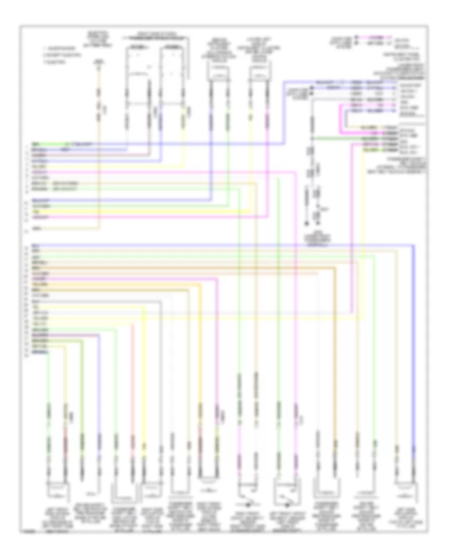
Supplemental Restraints Wiring Diagram (2 of 2) for Ford Focus ST 2014

Supplemental Restraints Wiring Diagram (2 of 2) for Ford Focus ST 2014 https://portal-diagnostov.com/license.html
https://portal-diagnostov.com/license.html Automotive Electricians Portal FZCO Automotive Electricians Portal FZCO
Obtenez l'accès à tous les schémas de câblage de la voitureDownload PDF file

List of elements for Supplemental Restraints Wiring Diagram (2 of 2) for Ford Focus ST 2014:

  • "c" pillar)
  • (behind instrument cluster) collapsible steering column module
  • (electric) upper high voltage battery pack
  • (lower left side of instrument cluster) driver lower air bag module
  • (right side of dash) passenger air bag module
  • (under front passenger's seat) occupant classification system module (ocsm)
  • Bts sig
  • Bts vref
  • C214
  • C237
  • C256a
  • C256b
  • C3007a
  • C3007b
  • C300b
  • Computer data lines system
  • Cr210
  • Driver safety belt anchor pretensioner (base of driver "b" pillar)
  • Driver safety belt retractor pretensioner (base of driver "b" pillar)
  • Electric
  • Ens
  • Except electric
  • G302 (under front passenger's door sill)
  • Gd140
  • Gnd
  • Hs can +
  • Hs can -
  • Instrument panel cluster (ipc)
  • Left front impact severity sensor (left front side of engine compt)
  • Left front side air bag module (outer edge of left front side
  • Left side air curtain module (top of left side "c" pillar)
  • Ms can+
  • Ms can-
  • Nca
  • Nca bts sig
  • Nca bts vref
  • Nca bucl sw +
  • Nca bucl sw -
  • Nca gnd
  • Passenger safety belt anchor pretensioner (base of passenger "b" pillar)
  • Passenger safety belt buckle (integral to passenger seat belt buckle assembly)
  • Passenger safety belt load limiting retractor (base of right "b" pillar)
  • Passenger safety belt retractor pretensioner (base of passenger "b" pillar)
  • Right front impact severity sensor (right front side of engine compt)
  • Right front side air bag module (outer edge of right front seat back)
  • Right side air curtain module (top of right side
  • Run/start
  • S301
  • Seat back)
  • Shorting bar
  • Stage 1
  • Stage 2
  • Vdb04
  • Vdb05
  • Vr210
  • Vr223