SUPPLEMENTAL RESTRAINTS
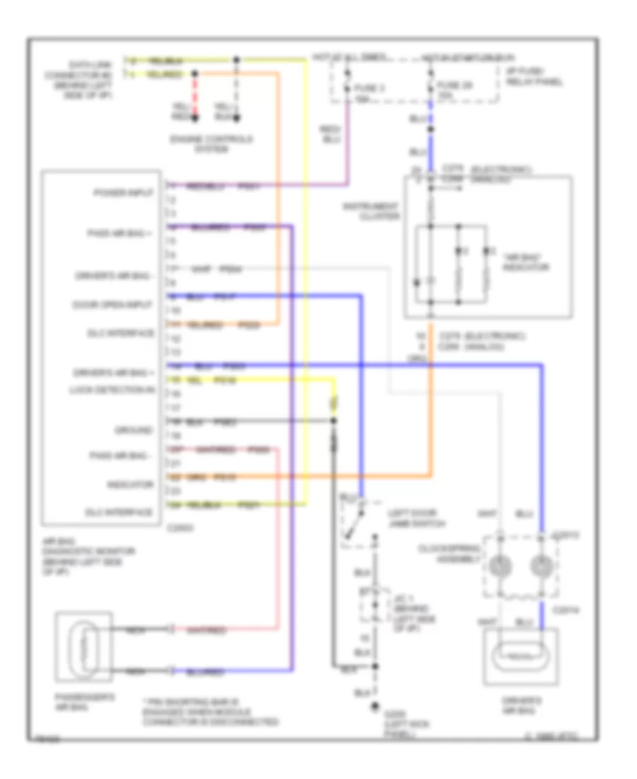
Supplemental Restraint Wiring Diagram for Mercury Villager GS 1996
List of elements for Supplemental Restraint Wiring Diagram for Mercury Villager GS 1996:
- "air bag" indicator
- * pin shorting bar is engaged when module connector is disconnected
- 14*
- 20*
- Air bag diagnostic monitor (behind left side of i/p)
- C 1995 vftc
- C2003
- C2013
- C2014
- C266
- C268
- C276 (electronic) (analog)
- Clockspring assembly
- Cluster
- Data link connector #2 (behind left side of i/p)
- Dlc interface
- Door open input
- Driver's air bag
- Driver's air bag +
- Driver's air bag -
- Engine controls system
- Fuse 29 10a
- Fuse 3 10a
- G200 (left kick panel)
- Ground
- Hot at all times
- Hot in start or run
- I/p fuse/ relay panel
- Indicator
- Instrument
- J/c 1 (behind left side of i/p)
- Left door jamb switch
- Lock detection in
- Nca
- Pass air bag +
- Pass air bag -
- Passenger's air bag
- Power input
- Ps01
- Ps03
- Ps04
- Ps05
- Ps06
- Ps15
- Ps17
- Ps18
- Ps20
- Ps21
- Pse2
 Čeština
 Dansk
Dansk Deutsch
 Ελληνικά
 English
 English
 Español
 Suomi
Suomi Français
 עברית
עברית Hrvatski
 Magyar
 Italiano
 日本語
日本語 한국어
한국어 Nederlands
 Polski
 Português
 Português
 Română
 Русский
 Slovenčina
 Slovenščina
 Svenska
 Türkçe
 中文 (中国)
 Français