STARTING/CHARGING
Charging Wiring Diagram for Pontiac Grand Prix GT 2004
 https://portal-diagnostov.com/license.html
Automotive Electricians Portal FZCO
Automotive Electricians Portal FZCO
https://portal-diagnostov.com/license.html
https://portal-diagnostov.com/license.html
Automotive Electricians Portal FZCO
Automotive Electricians Portal FZCO
List of elements for Charging Wiring Diagram for Pontiac Grand Prix GT 2004:
- (not used) a
- (not used) c
- Battery
- Battery positive voltage
- Charging system failure ind
- Data link connector (right of steering column)
- Displays fuse 10a
- Driver information center (dic)
- G102
- G111 (right side of engine, on ignition control module) bracket)
- Generator
- Generator turn on signal
- Hot at all times
- I/p fuse block (behind right side of dash, in glove box opening)
- Instrument panel cluster (ipc)
- Logic
- Message center
- Pcm class 2 serial data
- Pcm/ etc fuse 15a
- Powertrain control module (left front side of engine compartment, in air cleaner assembly)
- Red
- Sp205 (right side of upper left footwell)
- Starter
- Trip computer class 2 serial data
- Underhood fuse block (mounted to right strut tower)
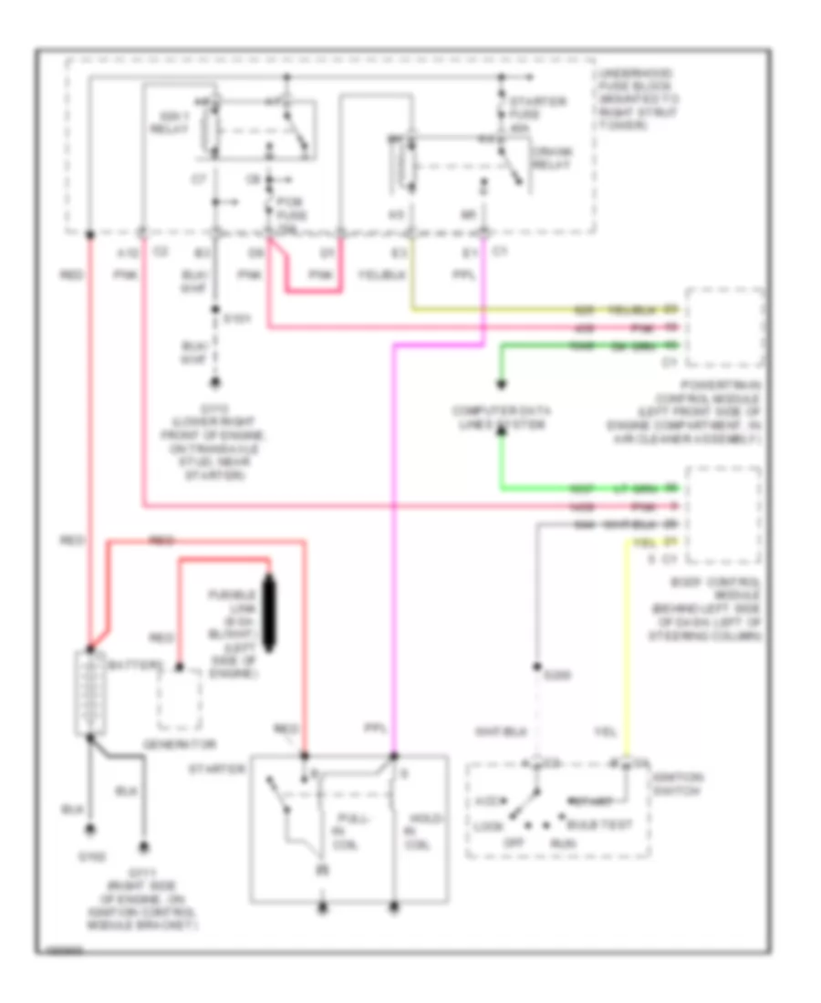
Starting Wiring Diagram for Pontiac Grand Prix GT 2004
List of elements for Starting Wiring Diagram for Pontiac Grand Prix GT 2004:
- A12
- Acc
- Battery
- Body control module (behind left side of dash, left of steering column)
- Bulb test
- Coil
- Computer data lines system
- Crank relay
- G102
- G111 (right side of engine, on ignition control module bracket)
- G113 (lower right front of engine, on transaxle stud, near starter)
- Generator
- Hold-
- Ign 1 relay
- Ignition switch
- Lock
- Off
- Pcm fuse 10a
- Pnk
- Powertrain control module (left front side of engine compartment, in air cleaner assembly)
- Pull-
- Red
- Run
- S101
- S200
- Start
- Starter
- Starter fuse 40a
- Underhood fuse block (mounted to right strut tower)

 Čeština
 Dansk
Dansk Deutsch
 Ελληνικά
 English
 English
 Español
 Suomi
Suomi Français
 עברית
עברית Hrvatski
 Magyar
 Italiano
 日本語
日本語 한국어
한국어 Nederlands
 Polski
 Português
 Português
 Română
 Русский
 Slovenčina
 Slovenščina
 Svenska
 Türkçe
 中文 (中国)