ENGINE PERFORMANCE
3.0L TURBO HYBRID
3.0L Turbo Hybrid, Engine Performance Wiring Diagram (1 of 8) for BMW ActiveHybrid 3 2014
 https://portal-diagnostov.com/license.html
Automotive Electricians Portal FZCO
Automotive Electricians Portal FZCO
https://portal-diagnostov.com/license.html
https://portal-diagnostov.com/license.html
Automotive Electricians Portal FZCO
Automotive Electricians Portal FZCO
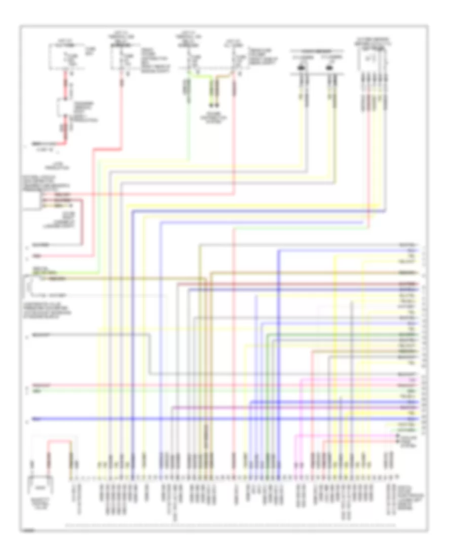
List of elements for 3.0L Turbo Hybrid, Engine Performance Wiring Diagram (1 of 8) for BMW ActiveHybrid 3 2014:
- (pins 16 to 19 not used)
- (right corner of luggage compt)
- (top of engine) z6000 1b
- (under engine valve cover) valvetronic actuator motor
- Accelerator pedal module (part accelerator pedal assembly)
- Brake vacuum sensor (on brake vacuum booster assembly)
- Computer data lines system
- Cooling fans system
- Cut-out relay
- Digital motor electronics (lower left side of engine)
- Dme main relay
- Electric fan
- Electrical exhaust flap (left side of rear compt)
- Eng start sig
- Environmental air catalyst sensor
- Flap activation
- Flexray bus sig
- Front electronic module (right end of dash)
- Fuel inj activation
- Fuel inj sply
- Fuel tank non return valve
- Fuel tank pressure sensor
- Fuel tank sig
- Fuse 15a
- Fuse 20a
- Fuse 40a
- Fuse 5a
- Gnd
- Hall sens gnd
- Hall sens sig
- Hall sens sply
- Hot w/ terminal 30b relay energized
- Ignition & fuel injection relay
- Leak detection sig
- Lin bus sig
- Motor position sensor
- Mtr activation
- Nca
- Pnk
- Pt-can bus sig
- Pt-can bus sig term 15 wake up sig
- Rear fuse holder (right side of rear compt)
- Red
- Rly activation
- Sens gnd
- Sens sig
- Sens sply
- Spd sig
- Sply
- Term 15 sply
- Valvetronic relay
- Vlv sply
- Z10 2b (right front corner of engine compt)
- Z10 6b (right footwell)
- Z10 9b
- Z11 1b
- Z11 3b
- Z11 4b
- Z8 3b
3.0L Turbo Hybrid, Engine Performance Wiring Diagram (2 of 8) for BMW ActiveHybrid 3 2014
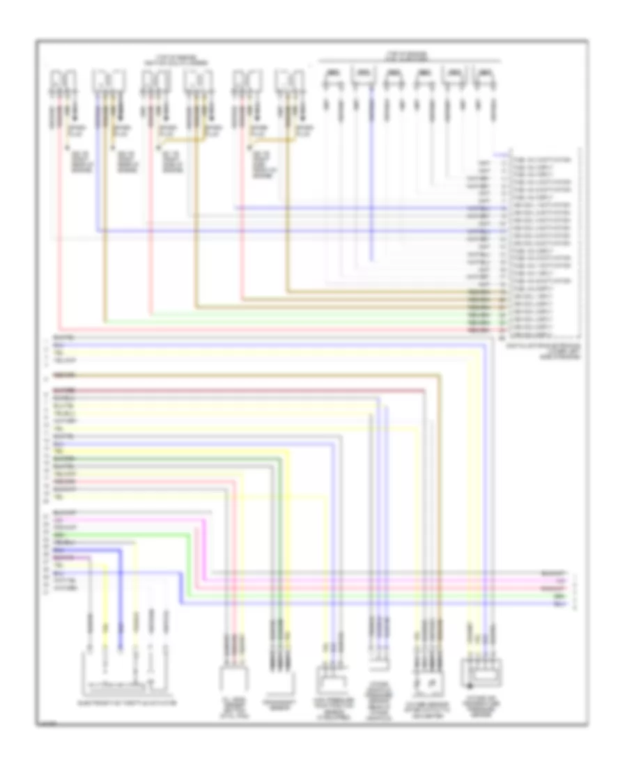
List of elements for 3.0L Turbo Hybrid, Engine Performance Wiring Diagram (2 of 8) for BMW ActiveHybrid 3 2014:
- Act activation
- Bsd bus sig
- Cool pmp
- Cooling fans system
- Cylinders 1-3
- Cylinders 4-6
- Digital motor electronics (lower left side of engine)
- Elec trtl act gnd
- Elec trtl act sig
- Front power distribution box (right rear of engine compt)
- Fuse 10a
- Fuse 125a
- Fuse 15a
- Fuse 5a
- Fuse box
- Hot at all times
- Hot w/ terminal 15n relay energized
- Hot w/ terminal 30b relay energized
- Knock sens sig
- Knock sensor
- Late production
- Natural vacuum leak detection temperature sensor & pressure switch
- Nca
- Oxygen sensor before catalytic converter
- Power distribution system
- Quantity control valve
- Rear fuse holder (right side of rear compt)
- Red
- Sens gnd
- Sens sig
- Sens sply
- Sply
- Transfer terminal point (early production)
- Vlv activation
- Vlv sply
- Wastegate valve pressure converter (w/o exhaust emissions standard euro 6)
- X1397 1b
- X541 1b
- X541 2b
- Z10 9b (right corner of luggage compt)
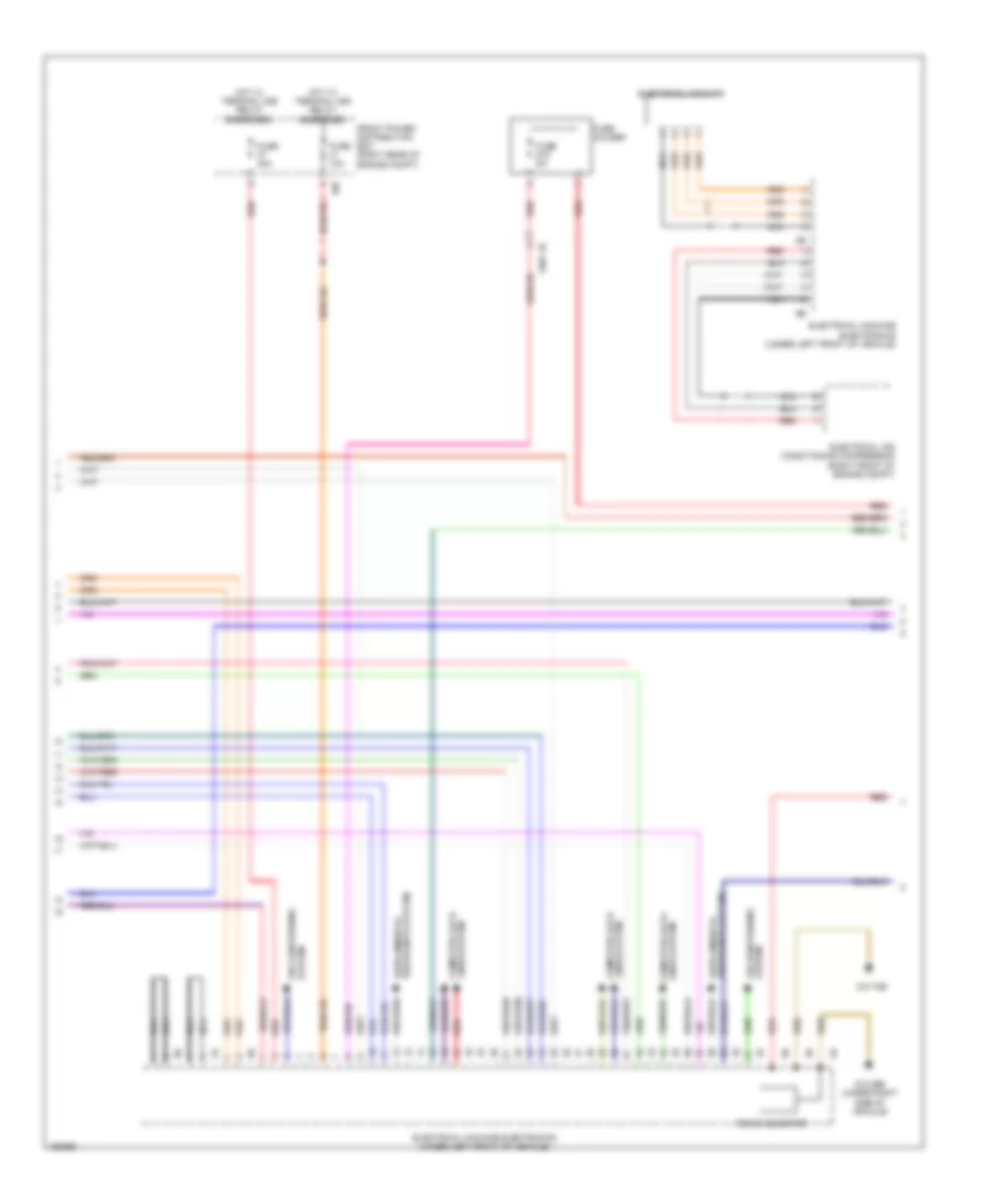
3.0L Turbo Hybrid, Engine Performance Wiring Diagram (3 of 8) for BMW ActiveHybrid 3 2014
List of elements for 3.0L Turbo Hybrid, Engine Performance Wiring Diagram (3 of 8) for BMW ActiveHybrid 3 2014:
- (top of engine) fuel injectors
- (top of engine) ignition coil cylinders
- Crankshaft sensor
- Digital motor electronics (lower left side of engine)
- Electromotive throttle actuator
- Fuel inj 1 activation
- Fuel inj 1 sply
- Fuel inj 2 activation
- Fuel inj 2 sply
- Fuel inj 3 activation
- Fuel inj 3 sply
- Fuel inj 4 activation
- Fuel inj 4 sply
- Fuel inj 5 activation
- Fuel inj 5 sply
- Fuel inj 6 activation
- Fuel inj 6 sply
- High pressure pump position sensor (if equipped)
- Ign coil 1 activation
- Ign coil 1 sply
- Ign coil 2 activation
- Ign coil 2 sply
- Ign coil 3 activation
- Ign coil 3 sply
- Ign coil 4 activation
- Ign coil 4 sply
- Ign coil 5 activation
- Ign coil 5 sply
- Ign coil 6 activation
- Ign coil 6 sply
- Intake air temperature pressure sensor
- Intake manifold pressure sensor (rear of intake manifold)
- Nca
- Oil level sensor (bottom of oil pan)
- Oxygen sensor after catalytic converter
- Spark plug
- Z20 1b (right side front of engine)
- Z21 1b (right side of engine)
- Z22 1b (right rear of engine)
3.0L Turbo Hybrid, Engine Performance Wiring Diagram (4 of 8) for BMW ActiveHybrid 3 2014
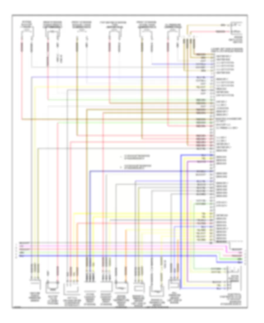
List of elements for 3.0L Turbo Hybrid, Engine Performance Wiring Diagram (4 of 8) for BMW ActiveHybrid 3 2014:
- (front of engine)
- (lower left side of engine) digital motor electronics
- (rear of engine) characteristic map thermostat
- (top center of engine)
- Bypass blow-off valve
- Electric changeover vlv sply
- Electrical wastegate valve (w/ exhaust emissions standard euro 6)
- Engine coolant temperature sensor (rear of engine)
- Engine oil pressure sensor (left side of engine)
- Engine oil temperature sensor (left side of engine)
- Engine ventilation heating
- Exhaust camshaft sensor (front of engine)
- Exhaust vanos solenoid valve
- Heater gnd
- Heater sply
- Hot film air mass meter (in engine air intake duct)
- Intake camshaft sensor (front of engine)
- Intake vanos solenoid valve
- Lin bus sig
- Map activation
- Map sply
- Meter gnd
- Meter sig
- Meter sply
- Mtr actv
- Nca
- Oil press vlv sply
- Oil pressure control valve
- Rail pressure sensor (left side of engine)
- Rotor position sensor
- Sens gnd
- Sens sig
- Sens sply
- Shutoff valve (w/ sport package)
- Shutoff vlv
- Tank venting valve
- Venture nozzle pressure sensor
- Vlv activation
- Vlv sply
- W/ exhaust emissions standard euro 6
- W/o exhaust emissions standard euro 6
- X704 1b
- X705 1b
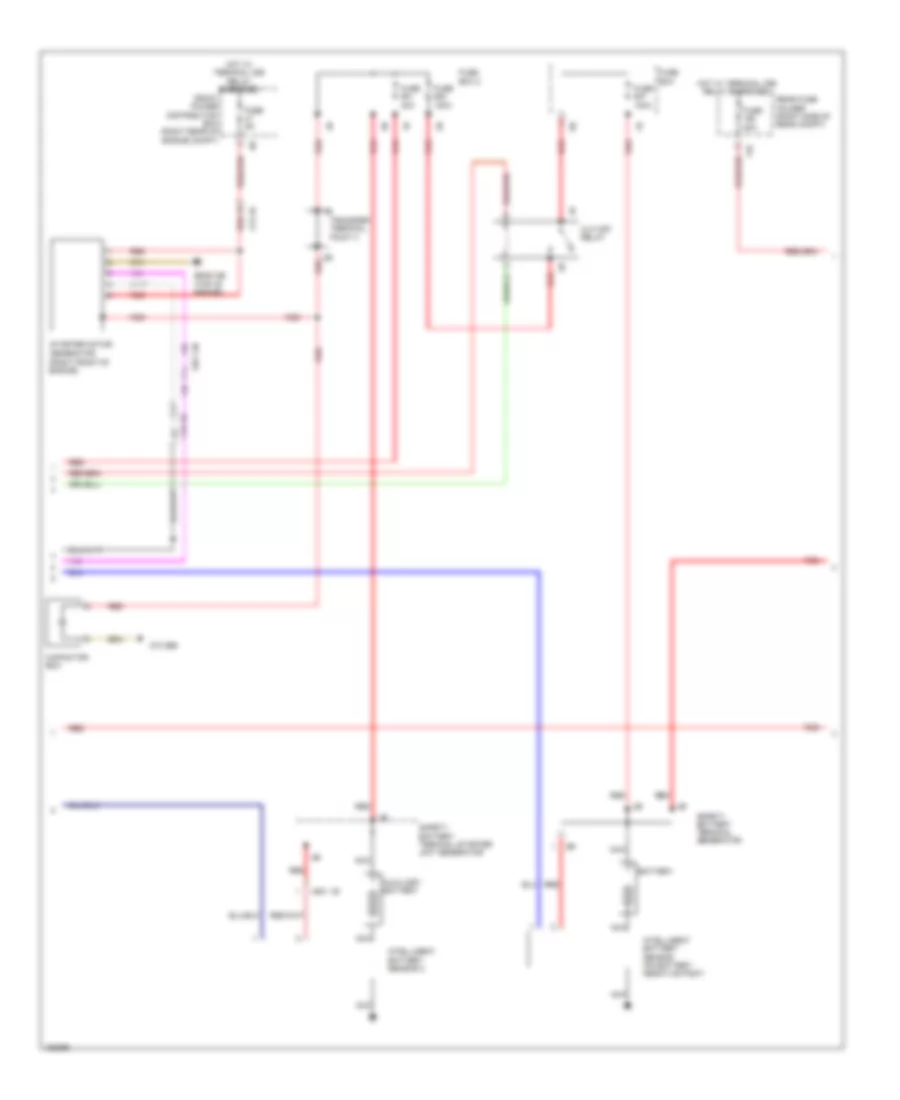
3.0L Turbo Hybrid, Engine Performance Wiring Diagram (5 of 8) for BMW ActiveHybrid 3 2014
List of elements for 3.0L Turbo Hybrid, Engine Performance Wiring Diagram (5 of 8) for BMW ActiveHybrid 3 2014:
- Accumulator management electronics
- Computer data lines system
- Electric vacuum pump
- Fuse 5a
- Fuse 7.5a
- High voltage safety connector (on hybrid 1b battery)
- Hot w/ bi-stable relay energized
- Hot w/ terminal 30b relay energized
- Nca
- Rear fuse holder (right side of rear compt)
- Refrigerant shutoff valve (high-voltage battery)
- Rotor position sensor (left side of transmission)
- Safety battery terminal generator 2b
- Temperature sensor (electrical machine)
- X13 8b
- X13 9b
- Z10 8b (on left rear wheelwell)
- Z6000 2b (top of engine)
- Z6000 3b (front of engine)
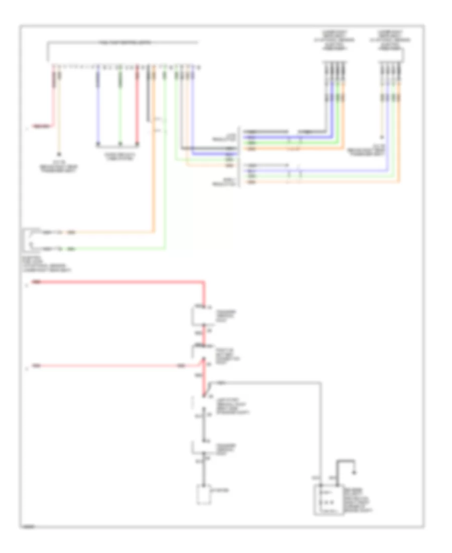
3.0L Turbo Hybrid, Engine Performance Wiring Diagram (6 of 8) for BMW ActiveHybrid 3 2014
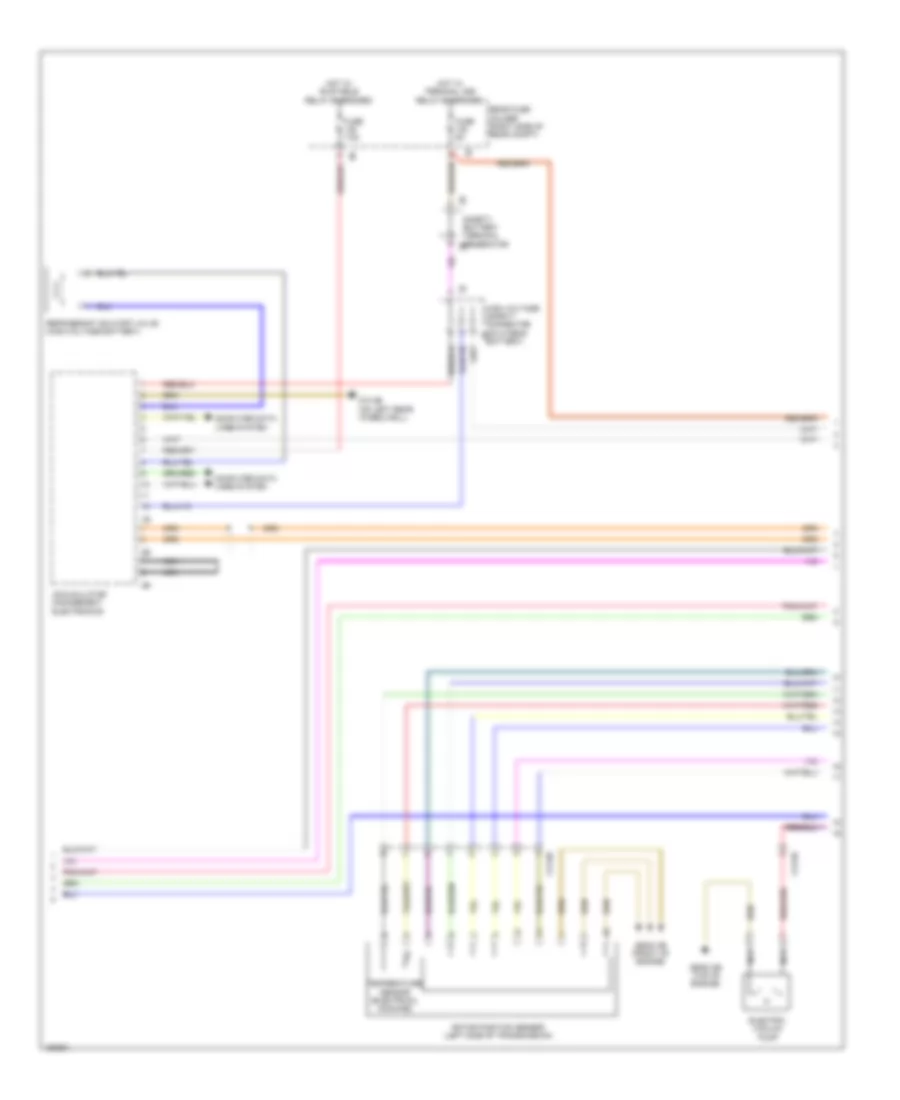
List of elements for 3.0L Turbo Hybrid, Engine Performance Wiring Diagram (6 of 8) for BMW ActiveHybrid 3 2014:
- 10b
- Air conditioning system
- Computer data lines system
- Dc/dc generter
- Electrical air conditioning compressor (right front of engine compt)
- Electrical machine
- Electrical machine electronics (under left front of vehicle)
- Front power distribution box (right rear of engine compt)
- Fuse 10a
- Fuse 40a
- Fuse 5a
- Fuse holder
- Hot w/ terminal 30b relay energized
- Nca
- Red
- System air conditioning
- X601 1b
- Z10 29b (under right side of vehicle)
- Z10 70b
3.0L Turbo Hybrid, Engine Performance Wiring Diagram (7 of 8) for BMW ActiveHybrid 3 2014
List of elements for 3.0L Turbo Hybrid, Engine Performance Wiring Diagram (7 of 8) for BMW ActiveHybrid 3 2014:
- (right front of engine)
- 11b
- Auxiliary battery
- Battery
- Capacitor box
- Cut-off relay
- Front power distribution box (right rear of engine compt)
- Fuse 100a
- Fuse 20a
- Fuse 40a
- Fuse 5a
- Fuse box
- Fuse box 2
- Hot w/ terminal 30b relay energized
- Intelligent battery sensor 2
- Nca
- Rear fuse holder (right side of rear compt)
- Red
- Safety battery terminal generator
- Safety battery terminal starter unit generator
- Starter motor generator
- Transfer terminal point 3
- X13 1b
- X601 1b
- X671 3b
- Z10 26b
- Z6000 2b (top of engine)
3.0L Turbo Hybrid, Engine Performance Wiring Diagram (8 of 8) for BMW ActiveHybrid 3 2014
List of elements for 3.0L Turbo Hybrid, Engine Performance Wiring Diagram (8 of 8) for BMW ActiveHybrid 3 2014:
- (under right rear seat) (w/ ethanol sensor) electric fuel pump
- Computer data lines system
- Early production
- Electric fuel pump (w/o ethanol sensor) (under right rear seat)
- Fuel pump control (ekps)
- Jump start terminal point (right side of engine compt)
- Late production
- Nca
- Positive battery connection point
- Red
- Red 1b
- Reverse polarity protection (right front corner of engine compt)
- Starter
- Transfer terminal point
- Z10 7b (behind right rear passenger seat)

 Čeština
 Dansk
Dansk Deutsch
 Ελληνικά
 English
 English
 Español
 Suomi
Suomi Français
 עברית
עברית Hrvatski
 Magyar
 Italiano
 日本語
日本語 한국어
한국어 Nederlands
 Polski
 Português
 Português
 Română
 Русский
 Slovenčina
 Slovenščina
 Svenska
 Türkçe
 中文 (中国)