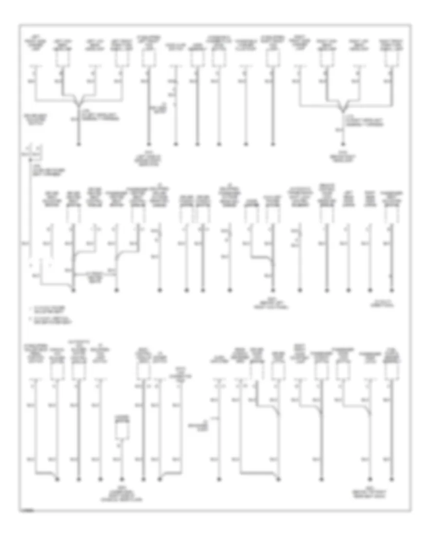
GROUND DISTRIBUTION
Ground Distribution Wiring Diagram (1 of 3) for Saturn Aura XE 2008
 https://portal-diagnostov.com/license.html
Automotive Electricians Portal FZCO
Automotive Electricians Portal FZCO
https://portal-diagnostov.com/license.html
https://portal-diagnostov.com/license.html
Automotive Electricians Portal FZCO
Automotive Electricians Portal FZCO
List of elements for Ground Distribution Wiring Diagram (1 of 3) for Saturn Aura XE 2008:
- (if equipped) adjustable pedal module
- (left side of engine compt, next to battery) underhood fuse block
- 2.4l (vin 5)
- 2.4l (vin 5) & 3.6l
- 3.5l
- 3.6l
- 3.6l & 3.5l
- 4 speed
- 6 speed
- 87a
- A/c compressor clutch
- A12
- Automatic a/c
- Battery
- Body control module (bcm)
- Brake fluid level switch
- C10
- Cool/fan ser/par relay 29
- Data link connector (dlc)
- Electronic brake control module (ebcm)
- Engine control module (ecm)
- Engine cooling fan diode
- Frt fog relay 36
- G104 (left side of engine compt, on core support)
- G105 (3.5l: under left intake manifold, on rear of cylinder head) (3.6l: center rear of engine) (2.4l: left rear of engine)
- G106 (2.4l (vin b): left rear of engine) (3.5l: rear of engine, above oil filter) (2.4l (vin 5): rear of engine, near pnp switch)
- G107 (right front of engine)
- G109 (left front engine compt, on core support)
- G111 (3.6l) (top rear right side of engine)
- G113 (3.6l) (on center left side cylinder head)
- G201 (under dash, right side of console, near floor)
- G306
- Generator battery disconnect control module
- Horn switch
- Hvac control module
- Ignition coil 1
- Ignition coil 2
- Ignition coil 3
- Ignition coil 4
- Ignition coil 5
- Ignition coil 6
- Ignition control module (icm)
- Inflatable restraint steering wheel module coil
- Instrument panel cluster (ipc)
- Intake manifold tuning (imt) solenoid valve
- J201 (in steering wheel controls harness, under left side of inflatable restraint steering wheel module)
- Left steering wheel control switch
- Manual a/c
- Mass air flow (maf)/ intake air temperature (iat) sensor
- Park/ neutral position (pnp) switch
- Radio
- Right engine cooling fan
- Right steering wheel control switch
- Run/crank relay 32
- Speed
- Stop lamp relay 49
- Theft deterrent module (tdm)
- Transmission control module (tcm)
- Turn signal/ multifunction switch
- Vehicle communi- cation interface module (vcim)
- W/ onstar
- Windshield wiper motor
- Wiper 1 relay 39
- Wiper 2 relay 40
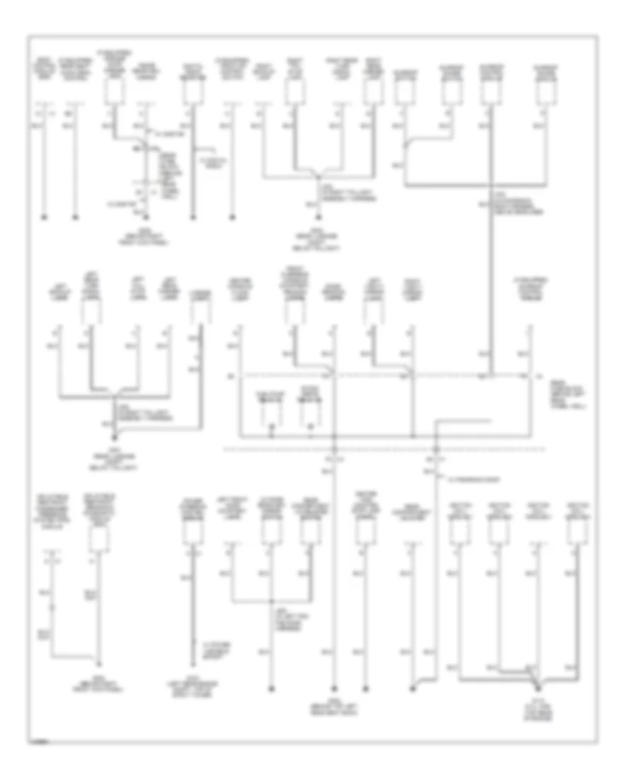
Ground Distribution Wiring Diagram (2 of 3) for Saturn Aura XE 2008
List of elements for Ground Distribution Wiring Diagram (2 of 3) for Saturn Aura XE 2008:
- (automatic a/c) blower motor control module
- (if equipped) adjustable pedal position switch
- (if equipped) driver outside rearview mirror
- (if equipped) fog lamp switch
- (if equipped) left front fog lamp
- (if equipped) passenger outside rearview mirror
- (if equipped) right front fog lamp
- (manual a/c) blower motor
- Adjuster seat
- Audio amplifier
- Automatic transmission shift lock control solenoid
- Auxiliary power outlet
- Body control module (bcm)
- Cigar lighter
- Data link connector (dlc)
- Driver door latch
- Driver door lock switch
- Driver heated seat control module
- Driver heated seat switch
- Driver seat adjuster switch
- Driver window motor
- Driver window switch
- E12
- Fuel pump & sender assembly
- G101 (left side of engine compt, near g109)
- G102 (behind right headlamp)
- G203 (under dash, right side of console, near floor)
- G301 (behind top right rear seat back)
- G303 (behind left front kick panel)
- Hazard switch
- Hood ajar switch
- Horn assembly
- I/p dimmer switch
- J110 (in right headlight assembly harness)
- J302 (in driver power seat harness)
- Left front park/turn signal lamp
- Left front side marker lamp
- Left high beam headlamp
- Left low beam headlamp
- Left rear door latch
- Nca
- Passenger door latch
- Passenger door lock switch
- Passenger heated seat control module
- Passenger heated seat switch
- Passenger seat adjuster switch
- Passenger window switch
- Rear window defogger grid
- Remote control door lock receiver (rcdlr)
- Right front door courtesy lamp
- Right front park/turn signal lamp
- Right front side marker lamp
- Right high beam headlamp
- Right low beam headlamp
- Right rear door latch
- W/ 2-way vertical driver power seat
- W/ 8-way power
- W/ enhanced audio
- W/ front heated seats
- W/ keyless entry
- W/ multi- directional
- Windshield washer fluid level switch
- Windshield washer fluid pump
Ground Distribution Wiring Diagram (3 of 3) for Saturn Aura XE 2008
List of elements for Ground Distribution Wiring Diagram (3 of 3) for Saturn Aura XE 2008:
- (if equipped) garage door opener (gdo)
- (if equipped) rear seat audio (rsa) control
- (if equipped) sunroof control module
- (if equipped) traction control switch
- Body control module (bcm)
- Center console flood lamp
- Center high mounted stop lamp (chmsl)
- Digital radio receiver
- Dome/ reading lamps
- Front overhead console courtesy/ reading lamps
- Fuel/pump relay 37
- G103 (left rear engine compt, top of strut tower)
- G110 (2.4l vin5) (top rear of engine)
- G302 (behind top left rear seat back)
- G304 (behind right front kick panel)
- G305 (behind right front kick panel)
- G401 (rear luggage compt, below taillight)
- G403 (rear luggage compt, below taillight)
- Ignition coil/ module 1
- Ignition coil/ module 2
- Ignition coil/ module 3
- Ignition coil/ module 4
- Inflatable restraint passenger presence system (pps) module
- Inflatable restraint sensing & diagnostic module (sdm)
- Inside rearview mirror
- J402 (in right taillight assembly harness)
- J403 (in panoramic roof harness, above headliner)
- J404 (in right taillight assembly harness)
- J500 (in left trim pad door harness)
- Left backup lamp
- Left front door courtesy lamp
- Left rear marker lamp
- Left rear turn signal lamp
- Left tail/ stop lamp
- Left vanity mirror lamp
- License lamp
- Nca
- Outside rearview mirror switch
- Power steering control module
- R/wdo defog relay 26
- Rear compartment lid latch
- Rear compartment lid release switch
- Rear fuse block (behind left rear wheel well)
- Right backup lamp
- Right rear marker lamp
- Right rear turn signal lamp
- Right tail/ stop lamp
- Right vanity mirror lamp
- Sunroof control module
- Sunroof shade module
- Sunroof shade switch
- Sunroof switch
- W/ digital radio
- W/ onstar
- W/ panoramic roof
- W/ power variable effort

 Čeština
 Dansk
Dansk Deutsch
 Ελληνικά
 English
 English
 Español
 Suomi
Suomi Français
 עברית
עברית Hrvatski
 Magyar
 Italiano
 日本語
日本語 한국어
한국어 Nederlands
 Polski
 Português
 Português
 Română
 Русский
 Slovenčina
 Slovenščina
 Svenska
 Türkçe
 中文 (中国)