POWER DISTRIBUTION
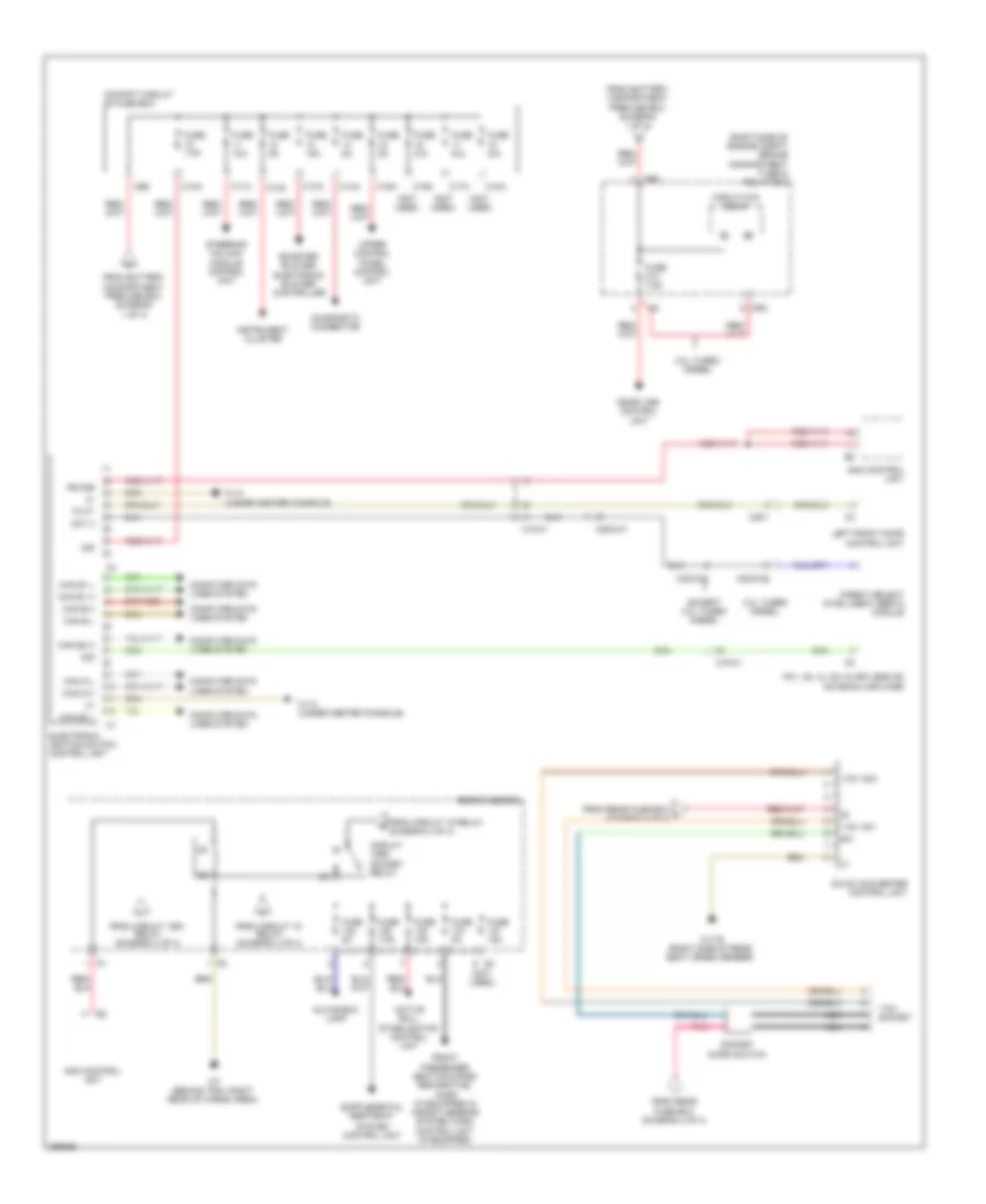
Power Distribution Wiring Diagram (1 of 4) for Mercedes-Benz ML550 2012
 https://portal-diagnostov.com/license.html
Automotive Electricians Portal FZCO
Automotive Electricians Portal FZCO
https://portal-diagnostov.com/license.html
https://portal-diagnostov.com/license.html
Automotive Electricians Portal FZCO
Automotive Electricians Portal FZCO
List of elements for Power Distribution Wiring Diagram (1 of 4) for Mercedes-Benz ML550 2012:
- (if equipped)
- (not used)
- (under right front seat) battery compartment prefuse box
- 85a
- 85b
- 86a
- 86b
- Ac housing
- Airmatic control unit
- Ata (edw)/ towing sensor/ interior motion sensor control unit
- Audio/ command control panel
- Battery sensor
- C4 red
- Circuit 30g relay
- E2b
- Eco start/ stop function diode (if equipped)
- Eco start/stop function diode (if equipped)
- Electric parking brake control unit
- Electrical power steering control unit
- Electronic stability program control unit
- Emergency call system control (if equipped)
- Engine compartment prefuse box
- Fan motor
- Fm1, am, cl (zv) & keyless go antenna amplifier
- Fuse 100a
- Fuse 10a
- Fuse 125a
- Fuse 150a
- Fuse 15a
- Fuse 200a
- Fuse 25a
- Fuse 30a
- Fuse 400a
- Fuse 40a
- Fuse 5a
- Fuse 7.5a
- Fuse n/a
- Fuse pyro fuse n/a
- Interior prefuse box
- K88
- Keyless go control unit (if equipped)
- Left front door control unit
- Left front reversible emergency tensioning retractor
- Left rear door control unit
- Lower control panel control unit & (w/ on-road/ off-road package & airmatic) off road operating panel control unit (w/ on-road/ off-road package)
- Mf1
- Multiple fuse 1
- On-board electrical system battery
- Overhead control panel control unit
- Panoramic sliding roof control module (w/ panoramic sliding roof) sliding roof control module (w/ glass electric sliding roof)
- Parking system control unit (if equipped)
- Ptc heater booster (if equipped)
- Rear air conditioning electronic blower controller (if equipped)
- Rear control unit
- Red
- Right front door control unit
- Right rear door control unit
- S10
- S12
- S13
- S14
- S15
- S16
- S18
- S22
- Sam control unit
- Sound system amplifier control unit (sound system)
- Sound system amplifier control unit (w/ sound system)
- To cockpit circuit 30 fuse box (diagram 2 of 4)
- To cockpit circuit 30g fuse box (diagram 4 of 4)
- To engine compartment fuse & relay box (diagram 2 of 4)
- To engine compartment fuse & relay box (diagram 3 of 4)
- To multiple fuse 2 (diagram 3 of 4)
- To rear fuse box (diagram 3 of 4)
- To rear fuse box (diagram 4 of 4)
- Transfer case control unit (on-road/ off-road package)
- X18-c2
- X25/2-c2
Power Distribution Wiring Diagram (2 of 4) for Mercedes-Benz ML550 2012
List of elements for Power Distribution Wiring Diagram (2 of 4) for Mercedes-Benz ML550 2012:
- (not used)
- (right side of engine compt) engine compartment fuse & relay box
- 115v ac1
- 115v ac2
- 115v socket
- 3.0l turbo diesel
- 30z
- Active roll stabilization control unit
- Booster blower electronic blower controller
- C10a
- C11a
- C12a
- C13a
- C14a
- C15a
- C16a
- C17a
- C18a
- C5e
- Can b h
- Can b l
- Can d h
- Can d l
- Can e1 h
- Can e1 l
- Can e2 h
- Can e2 l
- Circuit 15r2 socket relay
- Circuit 87m relay
- Cockpit circuit 30 fuse box
- Computer data lines system
- Dc/ac converter control unit
- Diagnostic connector
- Direct select intelligent servo module
- Electronic ignition switch control unit
- Except 3.0l turbo diesel
- Fm1, am, cl (zv) & keyless go antenna amplifier
- From battery compartment prefuse box (diagram 1 of 4)
- From circuit 15 relay (diagram 4 of 4)
- From circuit 15r1 relay (diagram 4 of 4)
- From rear fuse box (diagram 4 0f 4)
- From rear fuse box j (diagram 4 0f 4)
- Front passenger seat occupied recognition, acsr (if equipped) & weight sensing system (wss) control unit (if equipped)
- Fuse 10a
- Fuse 15a
- Fuse 5a
- Fuse 7.5a
- Fuse n/a
- Glove box lamp
- Instrument cluster
- Left front door control unit
- Me-sfi (me) control unit
- Mr2
- Nca
- Not 2
- Pb 30b
- Pnk
- Rear fuse box
- Sam control unit
- Socket micro switch
- Steering column module control unit
- System control unit
- Tk ft
- Upper control panel control unit
- W1/4 (under center console)
- W17/6 (right side of rear seat cross member)
- W7 (behind trim, right rear of cargo area)
- X18-c1
- X22/2-c1
- X22/2-c2
- X25/2-c1
- X35/1
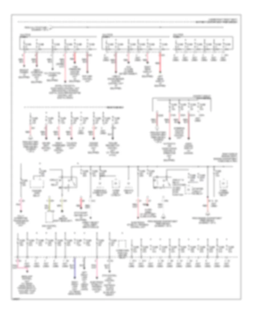
Power Distribution Wiring Diagram (3 of 4) for Mercedes-Benz ML550 2012
List of elements for Power Distribution Wiring Diagram (3 of 4) for Mercedes-Benz ML550 2012:
- (not used)
- (right side of engine compt) engine compartment fuse & relay box
- (under right front seat) battery compartment prefuse box
- (w/ eco start/ stop function)
- Airmatic relay
- Alarm siren (w/ anti-theft alarm system)
- Audio/ comand display (w/ comand)
- Automatic air conditioning control & operating unit (if equipped)
- Backup camera (if equipped)
- C19a
- C20a
- C20e
- C21a
- C22a
- Circuit
- Circuit 15 relay (unlatched)
- Cockpit circuit 30g fuse box
- Comand control unit (if equipped)
- Direct select intelligent servo module
- Driver seat control unit
- Dtr control unit control (w/ distronic plus & active blind spot assist)
- Dvd player (w/ rear entertainment)
- Electronic stability program control unit
- Fanfare horn relay
- From battery compartment prefuse box (diagram 1 of 4)
- From engine compartment prefuse box (diagram 1 of 4)
- From multiple fuse 1 c (diagram 1 of 4)
- Front passenger seat control unit
- Fully integrated transmission control unit
- Fuse 10a
- Fuse 15a
- Fuse 20a
- Fuse 240a 30a
- Fuse 240b 30a
- Fuse 25a
- Fuse 30a
- Fuse 5a
- Fuse 7.5a
- Fuse n/a
- Headlamp control unit (w/ xenon headlamps) & transmission oil auxiliary pump control unit
- Left front lamp unit (w/ xenon head- lamps)
- Left rear display (if equipped)
- Media interface control unit (if equipped)
- Mf2
- Mf3
- Mf4
- Mr1
- Mr2
- Multifunction camera (if equipped)
- Multiple fuse 2
- Multiple fuse 3
- Multiple fuse 4
- Pnk
- Rcp (hbf) control unit
- Rear fuse box
- Red
- Relay
- Right front lamp unit (w/ xenon headlamps)
- Right rear display (if equipped)
- S12
- S13
- S14
- S21
- Sam control unit
- Satellite digital audio radio control unit (sirius satellite radio) digital audio broadcasting control unit (digital radio)
- Starter circuit 50 relay
- Stationary heater unit (if equipped)
- Steering column module control unit
- Tailgate control unit
- Tire pressure monitor control unit (if equipped)
- Trailer recognition control unit (w/ trailer hitch)
- Turbo- charger relay
- Uh2
- Video & radar sensor system control unit (if equipped)
- W2 (behind right headlight)
- Windshield wiper on/off relay
- Wiper level 1/2 relay
- Wiper park position heater relay
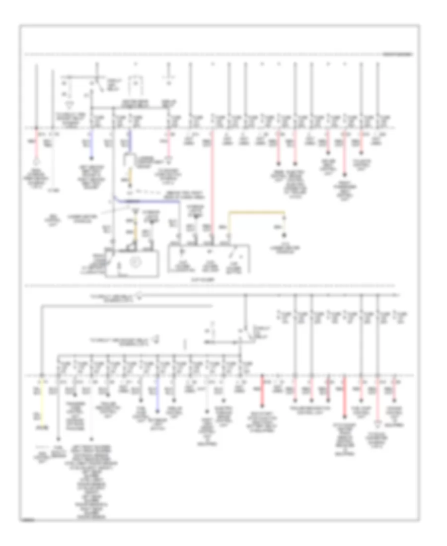
Power Distribution Wiring Diagram (4 of 4) for Mercedes-Benz ML550 2012
List of elements for Power Distribution Wiring Diagram (4 of 4) for Mercedes-Benz ML550 2012:
- (behind trim, right rear of cargo area)
- (not used)
- (under center console)
- Circuit 15r1 relay
- Circuit relay
- Comand control unit (if equipped)
- Cup holder
- Cup holder button
- Cup holder illumination
- Cup holder ind lamp
- Driver seat control unit
- E1a
- E1b
- Eco start/ stop function additional battery relay (if equipped)
- Electric brake control electric connector (w/ trailer hitch)
- Electric parking brake control unit
- Exterior light switch
- From interior prefuse box (diagram 1 of 4)
- Front cigar lighter w/ ashtray illumination
- Front passenger seat control unit
- Fuel pump control unit
- Fuel quality sensor
- Fuse 10a
- Fuse 15a
- Fuse 20a
- Fuse 25a
- Fuse 30a
- Fuse 40a
- Fuse 5a
- Fuse 7.5a
- Fuse n/a
- Heated rear window relay
- Interior lights system
- Left front bumper/ right front bumper/ distronic sensor, right rear bumper intelligent radar sensor (w/ blind spot assist), left rear bumper intelligent radar sensor (w/ blind spot assist), left rear bumper radar sensor & right rear bumper radar sensor
- Left second seat row socket & right second seat row socket
- Luggage compartment socket
- Nca
- Night view assist control unit (if equipped)
- Pnk
- Rear control unit
- Rear fuse box
- Red
- S10
- S11
- S12
- S13
- S14
- S18
- S19
- S20
- Sam control unit
- Stationary heater radio remote control reciever (if equipped)
- Tailgate control unit
- To circuit 15r2 relay (diagram 2 of 4)
- To circuit 15r2 socket relay (diagram 2 of 4)
- To dc/ac converter (diagram 4 of 4)
- To socket micro switch (diagram 4 of 4)
- Trailer recognition control unit
- Transfer case control unit (on-road/ off road package)
- W12
- W12 (under center console)
- X29/6-c1

 Čeština
 Dansk
Dansk Deutsch
 Ελληνικά
 English
 English
 Español
 Suomi
Suomi Français
 עברית
עברית Hrvatski
 Magyar
 Italiano
 日本語
日本語 한국어
한국어 Nederlands
 Polski
 Português
 Português
 Română
 Русский
 Slovenčina
 Slovenščina
 Svenska
 Türkçe
 中文 (中国)