AUTOMOTIVE ELECTRICIANS PORTAL

TRANSMISSION – Chevrolet Corvette Stingray 2014 – SYSTEM WIRING DIAGRAMS

TRANSMISSION

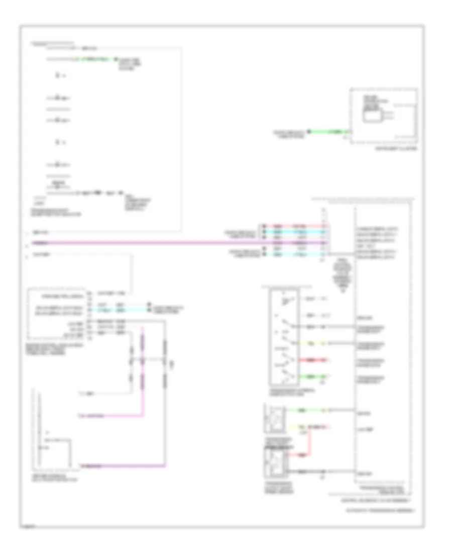
A/T Wiring Diagram (1 of 2) for Chevrolet Corvette Stingray 2014

AT Wiring Diagram (1 of 2) for Chevrolet Corvette Stingray 2014 https://portal-diagnostov.com/license.html
https://portal-diagnostov.com/license.html Automotive Electricians Portal FZCO Automotive Electricians Portal FZCO
Download PDF file

List of elements for A/T Wiring Diagram (1 of 2) for Chevrolet Corvette Stingray 2014:

  • A/t transmission fluid temperature (tft) sensor
  • Automatic transmission assembly
  • Body control module (bcm) (mounted on toe board, in right footwell)
  • Computer data lines system
  • Control solenoid valve assembly
  • G202 (under front of passenger's door sill)
  • G401 (left rear wheelwell)
  • Ground
  • Hot at all times
  • Hot w/ ignition main relay energized
  • Ign
  • J251
  • J252
  • Left transmission manual shift switch
  • Logic
  • Low ref
  • Pc 1 solenoid
  • Pc 2 solenoid
  • Pc 3 solenoid
  • Pc 4 solenoid
  • Pc 5 solenoid
  • Pressure control (pc) solenoid valve
  • Pressure control (pc) solenoid valve 1
  • Pressure control (pc) solenoid valve 2
  • Pressure control (pc) solenoid valve 3
  • Pressure control (pc) solenoid valve 4
  • Pressure control (pc) solenoid valve 5
  • Right transmission manual shift switch
  • Serial data (+)
  • Serial data (-)
  • Shift solenoid (ss) valve 1
  • Shift solenoid (ss) valve 2
  • Ss 1
  • Ss 2
  • Steering wheel air bag coil (top of steering column)
  • Tap up/tap down sw sig
  • Tccpc solenoid
  • Tcm fuse 15a
  • Tcm/ ecm fuse 15a
  • Tfp 1
  • Tfp 3
  • Tfp 4
  • Tfp 5
  • Tft
  • To transmission internal mode transmission switch (ims) (diagram 2 of 2)
  • Torque converter clutch (tcc)
  • Transmission control module (tcm)
  • Transmission fluid pressure switch
  • Underhood fuse block (left side of engine compt)
  • X174

A/T Wiring Diagram (2 of 2) for Chevrolet Corvette Stingray 2014

AT Wiring Diagram (2 of 2) for Chevrolet Corvette Stingray 2014 https://portal-diagnostov.com/license.html
https://portal-diagnostov.com/license.html Automotive Electricians Portal FZCO Automotive Electricians Portal FZCO
Obtenez l'accès à tous les schémas de câblage de la voitureDownload PDF file

List of elements for A/T Wiring Diagram (2 of 2) for Chevrolet Corvette Stingray 2014:

  • Automatic transmission assembly
  • Brake
  • Center console multi-function switch
  • Computer data lines system
  • Control solenoid valve assembly
  • Driver information center display
  • Engine control module (ecm) (behind right front wheelwell fender)
  • From control solenoid valve assembly (diagram 1 of 2)
  • G201 (under front of driver's door sill)
  • Gmlan serial data +
  • Gmlan serial data -
  • Gmlan serial data bus + x1
  • Gmlan serial data bus -
  • Ground
  • Ign i volt
  • Instrument cluster
  • Iss sig
  • J127
  • J203
  • Logic
  • Low ref
  • Oss sig
  • P/n
  • Park/neutral signal x2
  • Red
  • Sw 5v ref
  • Sw sig
  • Transmission control module (tcm)
  • Transmission input shaft speed sensor
  • Transmission internal mode switch (ims)
  • Transmission output shaft speed sensor
  • Transmission range sig a
  • Transmission range sig b
  • Transmission range sig c
  • Transmission range sig p
  • Transmission shift lever position indicator
  • Wakeup serial data
  • X100

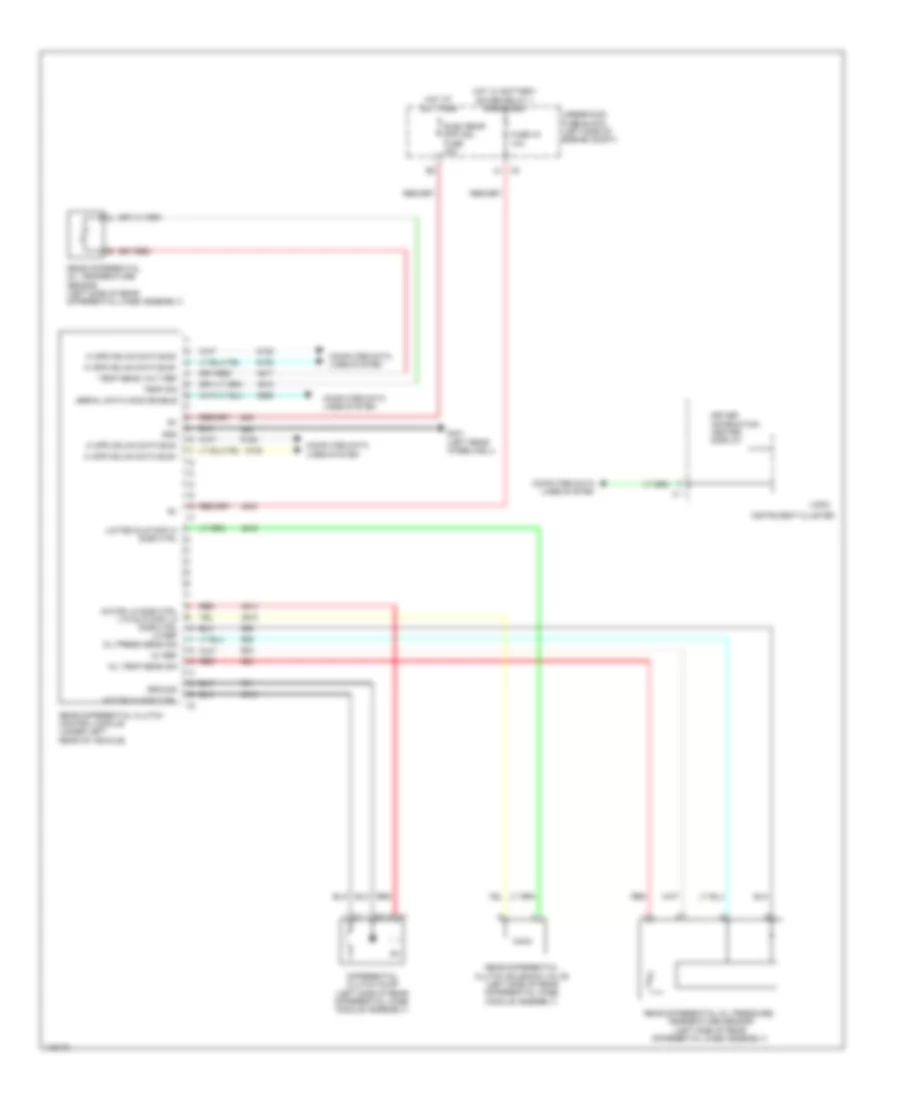
Rear Differential Lock Wiring Diagram for Chevrolet Corvette Stingray 2014

Rear Differential Lock Wiring Diagram for Chevrolet Corvette Stingray 2014 https://portal-diagnostov.com/license.html
https://portal-diagnostov.com/license.html Automotive Electricians Portal FZCO Automotive Electricians Portal FZCO
Obtenez l'accès à tous les schémas de câblage de la voitureDownload PDF file

List of elements for Rear Differential Lock Wiring Diagram for Chevrolet Corvette Stingray 2014:

  • 5v ref
  • Computer data lines system
  • Differential clutch pump (left side of rear differential case module assembly)
  • Driver information center display
  • Elec rear diff mdl fuse 40a
  • Fuse 43 10a
  • G401 (left rear wheelwell)
  • Gnd
  • Ground
  • Hi spd gmlan data bus+
  • Hi spd gmlan data bus-
  • Hot at all times
  • Hot w/ battery saver relay 1 energized
  • Instrument cluster
  • Limited slip diff hi side ctrl
  • Logic
  • Motor hi side ctrl
  • Motor lo side ctrl ltd slip diff lo side ctrl lo ref
  • Oil press sens sig
  • Oil temp sens sig
  • Rear differential clutch control module (under left rear of vehicle)
  • Rear differential clutch solenoid valve (left side of rear differential case module assembly)
  • Rear differential oil pressure/ temperature sensor (left side of rear differential case assembly)
  • Rear differential oil temperature sensor (left side of rear differential case assembly)
  • Red
  • Serial data comm enable
  • Temp sens volt ref
  • Temp sig
  • Underhood fuse block (left side of engine compt)